backflow prevention certification workshop booklet - · pdf filein case of a backflow incident...
TRANSCRIPT
page i
Information & Materials
Bureau of Water
Certification Workshop

The information enclosed in this bookletconsists of memos, policy statements and
other pertinent information to guide you in the establishment of a backflow prevention program.

TABLE OF CONTENTS
Notice of Approved Backflow Prevention Assemblies for S.C. ........................ 1
DHEC List of Approved Backflow Prevention Assemblies ............................... 3
Backflow Equipment Representatives ........................................................... 10
A Backflow Prevention Program Consists of ................................................. 11
In Case of a Backflow Incident ....................................................................... 12
Determining Backflow Protection for Various Facilities .................................. 13
Backflow Prevention Assembly Test Kit Information ...................................... 16
Backflow Prevention Testing Tips .................................................................. 17
DCVA/Vertical Tube (Direction Of Flow) .......................................................... 18
DCVA/Differential 3 Valve Gauge (Direction of Flow) ..................................... 20
DCVA/Differential 5 Valve Gauge (Direction of Flow) ..................................... 21
DCVA/Differential 3 Valve Gauge (Differential Pressure Test) ......................... 22
DCVA/Differential 5 Valve Gauge (Differential Pressure Test) ......................... 24
PVB/Differential 3 Valve Gauge (Direction of Flow) ........................................ 26
PVB/Differential 5 Valve Gauge (Direction of Flow) ........................................ 27
RPPA/Differential 3 Valve Gauge (Differential Pressure Test) ......................... 28
RPPA/Differential 5 Valve Gauge (Differential Pressure Test) ......................... 30
Backflow Assembly Test Report Form ........................................................ 32
Where To Send Differential Gauge for Calibration .......................................... 33
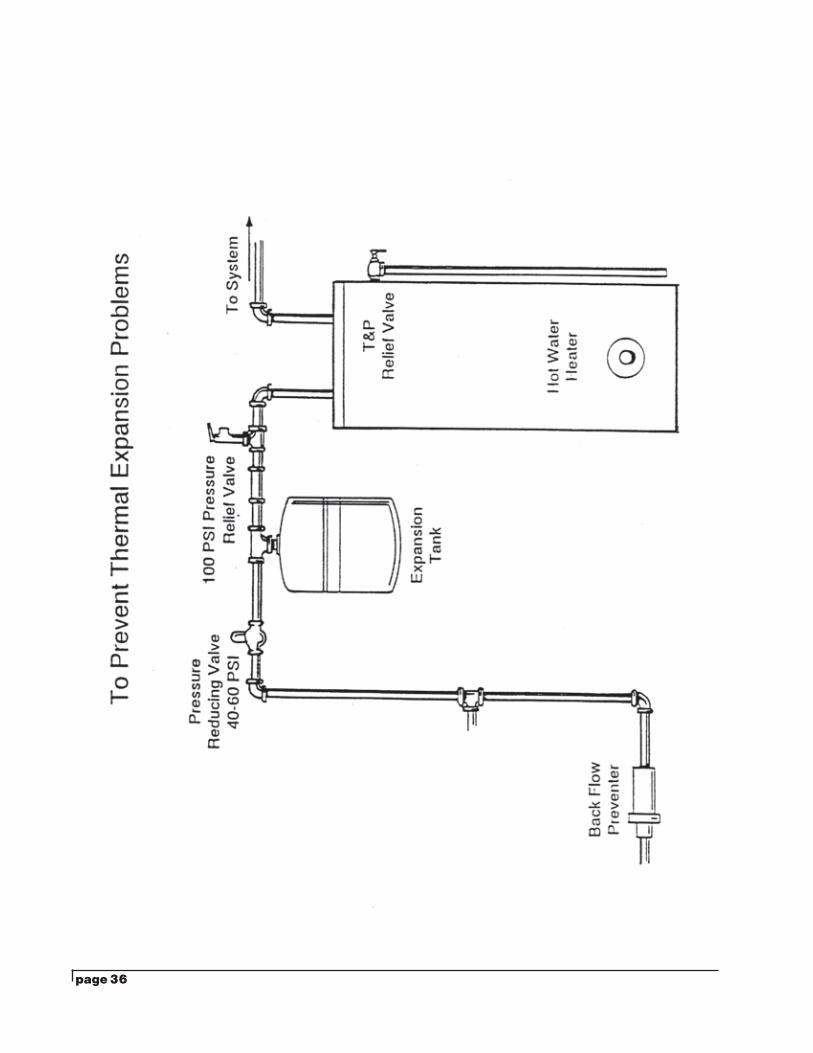
How To Prevent Thermal Expansion ............................................................. 35
Expansion/Bladder Tank ................................................................................ 36
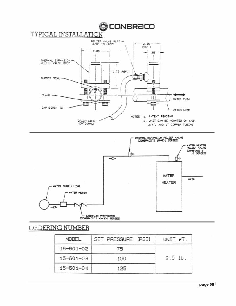
Thermal Expansion Relief Valve ..................................................................... 37
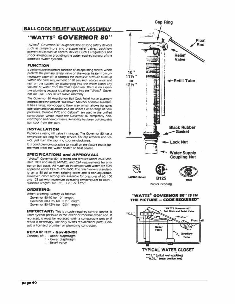
Ball Cock Relief Valve Assembly .................................................................... 39
Drinking Water & Backflow Prevention Magazine .......................................... 40
ASSE Series 5000 Booklet ............................................................................. 41
AWWA Manual M 14 ...................................................................................... 42
TREEO Backflow Prevention Theory & Practice Publication ......................... 43
USCFCCC & HR Manual of Cross Connection Control (Ninth Edition) .......... 44
Astra Industrial Services (Backflow Handbook) ............................................. 45
Backflow Apparatus & Valve Company (BAVCO) Handbook ......................... 46
Above Ground Backflow Enclosures .............................................................. 47

page 1
December 12, 2017 NOTICE OF APPROVED BACKFLOWPREVENTIVE ASSEMBLIES FOR SOUTH CAROLINA
Enclosed is the revised list of approved backflow prevention assemblies and a list of backflow equipment representatives.
The following should be considered before selecting a particular device:
1. All local plumbing laws and regulations must be adhered to.
2. Manufacturer's installation instructions shall be strictly adhered to.
3. Reduced pressure principle assemblies shall be installed so that the relief port will never become submerged. This prohibits installation in a pit that cannot be drained by gravity to the surface of the ground. Also, RPPA are not acceptable for the vertical orientation unless approved by the University of Southern California’s Foundation for Cross Connection Control & Hydraulic Research.
4. The operating performance of these assemblies varies among manufacturers; therefore, it is suggested that local water authorities be contacted to assist in selecting a assembly which is best suited for that particular system.
5. The South Carolina Department of Health and Environmental Control reserves the right to add or to remove from the approved list any reduced pressure principle assembly, pressure vacuum breaker, or double check valve assembly.
6. It is a requirement that backflow prevention assemblies be tested immediately after installation and at least once a year thereafter. If a serious defect is discovered at the time of the first (immediate inspection after installation) inspection or after any subsequent inspections, it is requested that the Department of Health and Environmental Control be notified so prompt action can be taken to review the approved status of the assembly.
7. By-pass piping is not permitted unless the by-pass piping is equipped with an approved backflow prevention assembly similar to the main line assembly. In many instances it will be desirable, or necessary to install two approved backflow prevention assemblies in order that water service will not be interrupted during the testing or repair of the assembly.
page 2
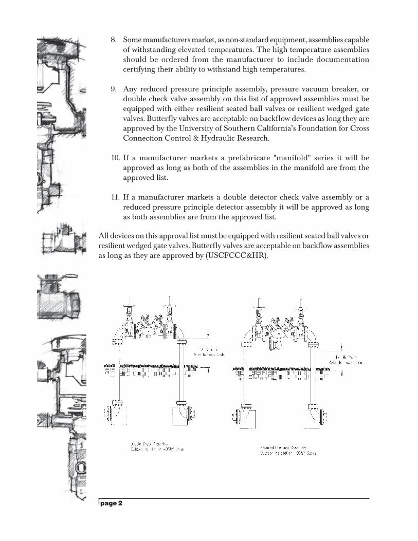
8. Some manufacturers market, as non-standard equipment, assemblies capable of withstanding elevated temperatures. The high temperature assemblies should be ordered from the manufacturer to include documentation certifying their ability to withstand high temperatures.
9. Any reduced pressure principle assembly, pressure vacuum breaker, or double check valve assembly on this list of approved assemblies must be equipped with either resilient seated ball valves or resilient wedged gate valves. Butterfly valves are acceptable on backflow devices as long they are approved by the University of Southern California’s Foundation for Cross Connection Control & Hydraulic Research.
10. If a manufacturer markets a prefabricate "manifold" series it will be approved as long as both of the assemblies in the manifold are from the approved list.
11. If a manufacturer markets a double detector check valve assembly or a reduced pressure principle detector assembly it will be approved as long as both assemblies are from the approved list.
All devices on this approval list must be equipped with resilient seated ball valves or resilient wedged gate valves. Butterfly valves are acceptable on backflow assemblies as long as they are approved by (USCFCCC&HR).
page 3
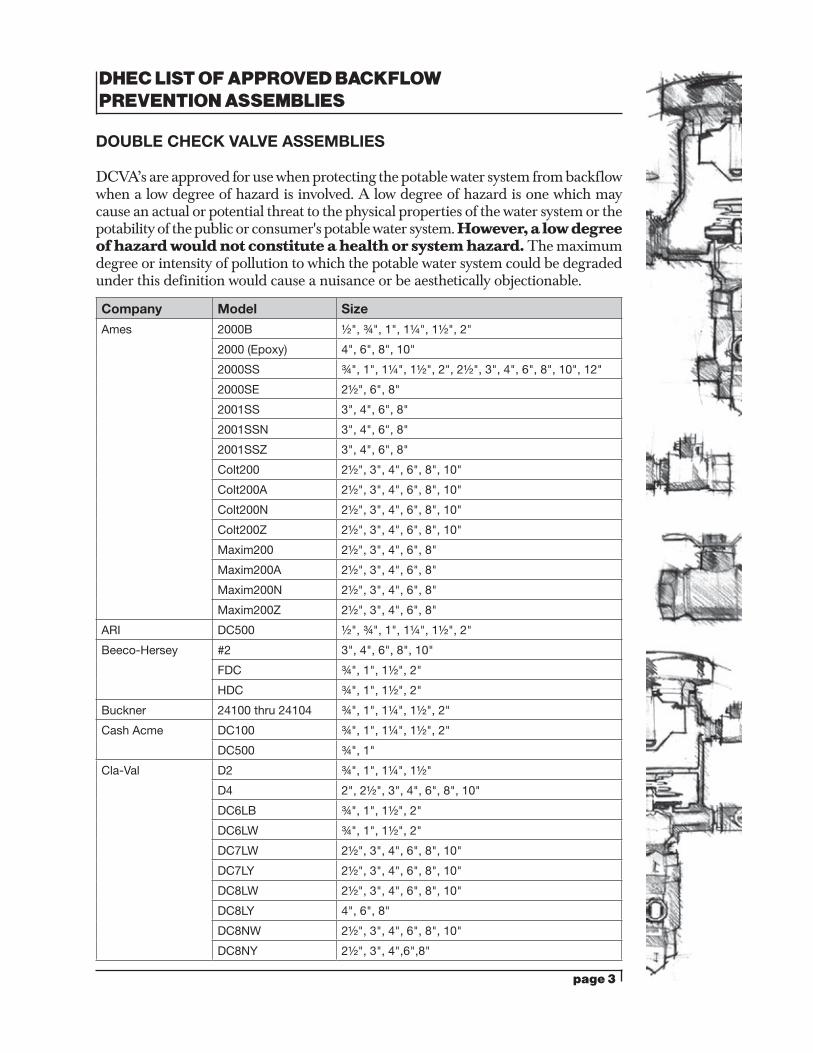
DHEC LIST OF APPROVED BACKFLOW PREVENTION ASSEMBLIES
DOUBLE CHECK VALVE ASSEMBLIES
DCVA’s are approved for use when protecting the potable water system from backflow when a low degree of hazard is involved. A low degree of hazard is one which may cause an actual or potential threat to the physical properties of the water system or the potability of the public or consumer's potable water system. However, a low degree of hazard would not constitute a health or system hazard. The maximum degree or intensity of pollution to which the potable water system could be degraded under this definition would cause a nuisance or be aesthetically objectionable.
Company Model Size
Ames 2000B ½", ¾", 1", 1¼", 1½", 2"
2000 (Epoxy) 4", 6", 8", 10"
2000SS ¾", 1", 1¼", 1½", 2", 2½", 3", 4", 6", 8", 10", 12"
2000SE 2½", 6", 8"
2001SS 3", 4", 6", 8"
2001SSN 3", 4", 6", 8"
2001SSZ 3", 4", 6", 8"
Colt200 2½", 3", 4", 6", 8", 10"
Colt200A 2½", 3", 4", 6", 8", 10"
Colt200N 2½", 3", 4", 6", 8", 10"
Colt200Z 2½", 3", 4", 6", 8", 10"
Maxim200 2½", 3", 4", 6", 8"
Maxim200A 2½", 3", 4", 6", 8"
Maxim200N 2½", 3", 4", 6", 8"
Maxim200Z 2½", 3", 4", 6", 8"
ARI DC500 ½", ¾", 1", 1¼", 1½", 2"
Beeco-Hersey #2 3", 4", 6", 8", 10"
FDC ¾", 1", 1½", 2"
HDC ¾", 1", 1½", 2"
Buckner 24100 thru 24104 ¾", 1", 1¼", 1½", 2"
Cash Acme DC100 ¾", 1", 1¼", 1½", 2"
DC500 ¾", 1"
Cla-Val D2 ¾", 1", 1¼", 1½"
D4 2", 2½", 3", 4", 6", 8", 10"
DC6LB ¾", 1", 1½", 2"
DC6LW ¾", 1", 1½", 2"
DC7LW 2½", 3", 4", 6", 8", 10"
DC7LY 2½", 3", 4", 6", 8", 10"
DC8LW 2½", 3", 4", 6", 8", 10"
DC8LY 4", 6", 8"
DC8NW 2½", 3", 4", 6", 8", 10"
DC8NY 2½", 3", 4",6",8"
page 4
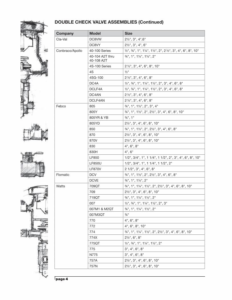
DOUBLE CHECK VALVE ASSEMBLIES (Continued)
Company Model Size
Cla-Val DC8VW 2½", 3", 4",6"
DC8VY 2½", 3", 4", 6"
Conbraco/Apollo 40-100 Series ½", ¾", 1", 1¼", 1½", 2", 2 ½", 3", 4", 6", 8", 10"
40-104 A2T thru 40-108 A2T
¾", 1", 1¼", 1½", 2"
4S-100 Series 2 ½", 3", 4", 6", 8", 10"
4S ½"
4SG-100 2 ½", 3", 4", 6", 8"
DC4A ½", ¾", 1", 1¼", 1½", 2", 3", 4", 6", 8"
DCLF4A ½", ¾", 1", 1¼", 1½", 2", 3", 4", 6", 8"
DC4AN 2 ½", 3", 4", 6", 8"
DCLF4AN 2 ½", 3", 4", 6", 8"
Febco 805 ¾", 1", 1½", 2", 3", 4"
805Y ¾", 1", 1½", 2", 2½", 3", 4", 6", 8", 10"
805YR & YB ¾", 1"
805YD 2½", 3", 4", 6", 8", 10"
850 ¾", 1", 1½", 2", 2½", 3", 4", 6", 8"
870 2½", 3", 4", 6", 8", 10"
870V 2½", 3", 4", 6", 8", 10"
830 4", 6", 8"
830H 4", 6"
LF850 1/2", 3/4", 1", 1 1/4", 1 1/2", 2", 3", 4", 6", 8", 10"
LF850U 1/2", 3/4", 1", 1 1/4", 1 1/2", 2"
LF870V 2 1/2", 3", 4", 6", 8"
Flomatic DCV ¾", 1", 1½", 2", 2½", 3", 4", 6", 8"
DCVE ¾", 1", 1½", 2"
Watts 709QT ¾", 1", 1¼", 1½", 2", 2½", 3”, 4", 6", 8", 10"
709 2½", 3", 4", 6", 8", 10"
719QT ¾", 1", 1¼", 1½", 2"
007 ½", ¾", 1", 1¼", 1½", 2", 3"
007M1 & M2QT ¾", 1", 1¼", 1½", 2"
007M3QT ¾"
770 4", 6", 8"
772 4", 6", 8", 10"
774 ¾", 1", 1¼", 1½", 2", 2½", 3", 4", 6", 8", 10"
774X 2½", 6", 8"
775QT ½", ¾", 1", 1¼", 1½", 2"
775 3", 4", 6", 8"
N775 3", 4", 6", 8"
757A 2½", 3", 4", 6", 8", 10"
757N 2½", 3", 4", 6", 8", 10"
page 5
Watts 767A 2½", 3", 4", 6", 8"
767N 2½", 3", 4"
Wilkins 350 & XL ¾", 1", 1¼", 1½", 2", 2½", 3", 4", 6", 8", 10", 12"
350A 2 1/2", 3", 4", 6", 8", 10"
350AR & ARXL 2 1/2", 3", 4", 6", 8", 10"
350AST 2 1/2", 3", 4", 6", 8", 10"
350ASTR 2½", 3", 4", 6"
350AXL 2 1/2", 3", 4", 6", 8", 10"
450 & XL 2½", 3", 4", 6", 8", 10"
550 ¾", 1", 1¼", 1½", 2", 2½", 3", 4", 6", 8", 10"
950 ¾", 1", 1¼", 1½", 2", 2½", 3", 4", 6", 8", 10"
950A ¾", 1", 1¼", 1½", 2"
950XLD ¾", 2"
950XLTU ¾", 1"
950XLT ¾", 1", 1¼", 1½", 2"
950XL ¾", 1", 1¼", 1½", 2"
950XLU ¾", 1", 1½", 2"
950XLTDA &XLTDABF
2"
950XLT2 ¾", 1", 1½", 2"
950XLT2U ¾"
page 6
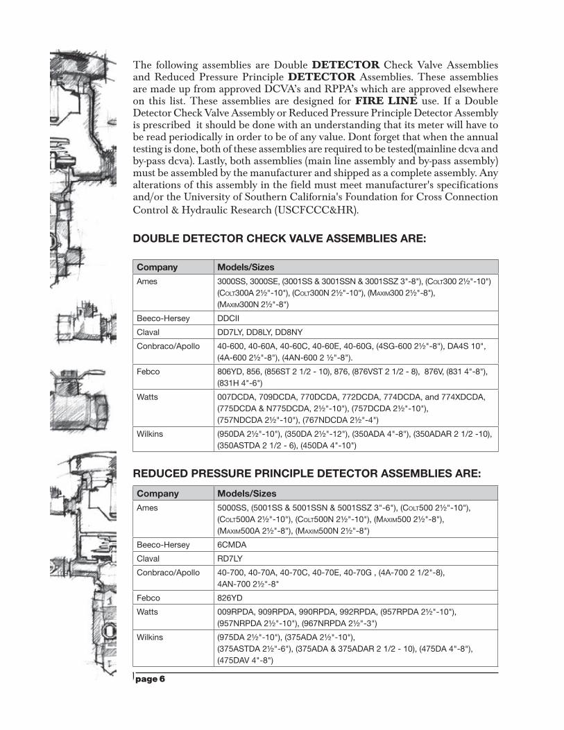
The following assemblies are Double DETECTOR Check Valve Assemblies and Reduced Pressure Principle DETECTOR Assemblies. These assemblies are made up from approved DCVA’s and RPPA’s which are approved elsewhere on this list. These assemblies are designed for FIRE LINE use. If a Double Detector Check Valve Assembly or Reduced Pressure Principle Detector Assembly is prescribed it should be done with an understanding that its meter will have to be read periodically in order to be of any value. Dont forget that when the annual testing is done, both of these assemblies are required to be tested(mainline dcva and by-pass dcva). Lastly, both assemblies (main line assembly and by-pass assembly) must be assembled by the manufacturer and shipped as a complete assembly. Any alterations of this assembly in the field must meet manufacturer's specifications and/or the University of Southern California's Foundation for Cross Connection Control & Hydraulic Research (USCFCCC&HR). DOUBLE DETECTOR CHECK VALVE ASSEMBLIES ARE:
Company Models/Sizes
Ames 3000SS, 3000SE, (3001SS & 3001SSN & 3001SSZ 3"-8"), (Colt300 2½"-10") (Colt300A 2½"-10"), (Colt300N 2½"-10"), (MAxiM300 2½"-8"), (MAxiM300N 2½"-8")
Beeco-Hersey DDCii
Claval DD7lY, DD8lY, DD8NY
Conbraco/Apollo 40-600, 40-60A, 40-60C, 40-60E, 40-60G, (4SG-600 2½"-8"), DA4S 10", (4A-600 2½"-8"), (4AN-600 2 ½"-8").
Febco 806YD, 856, (856St 2 1/2 - 10), 876, (876VSt 2 1/2 - 8), 876V, (831 4"-8"), (831H 4"-6")
Watts 007DCDA, 709DCDA, 770DCDA, 772DCDA, 774DCDA, and 774xDCDA, (775DCDA & N775DCDA, 2½"-10"), (757DCDA 2½"-10"), (757NDCDA 2½"-10"), (767NDCDA 2½"-4")
Wilkins (950DA 2½"-10"), (350DA 2½"-12"), (350ADA 4"-8"), (350ADAR 2 1/2 -10), (350AStDA 2 1/2 - 6), (450DA 4"-10")
REDUCED PRESSURE PRINCIPLE DETECTOR ASSEMBLIES ARE:
Company Models/Sizes
Ames 5000SS, (5001SS & 5001SSN & 5001SSZ 3"-6"), (Colt500 2½"-10"), (Colt500A 2½"-10"), (Colt500N 2½"-10"), (MAxiM500 2½"-8"), (MAxiM500A 2½"-8"), (MAxiM500N 2½"-8")
Beeco-Hersey 6CMDA
Claval RD7lY
Conbraco/Apollo 40-700, 40-70A, 40-70C, 40-70E, 40-70G , (4A-700 2 1/2"-8), 4AN-700 2½"-8"
Febco 826YD
Watts 009RPDA, 909RPDA, 990RPDA, 992RPDA, (957RPDA 2½"-10"), (957NRPDA 2½"-10"), (967NRPDA 2½"-3")
Wilkins (975DA 2½"-10"), (375ADA 2½"-10"), (375AStDA 2½"-6"), (375ADA & 375ADAR 2 1/2 - 10), (475DA 4"-8"), (475DAV 4"-8")
)
page 7
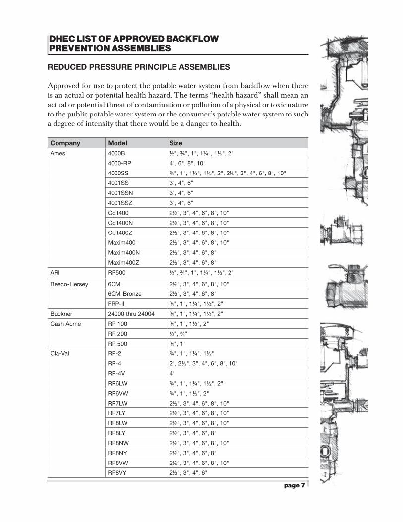
DHEC LIST OF APPROVED BACKFLOW PREVENTION ASSEMBLIES
REDUCED PRESSURE PRINCIPLE ASSEMBLIES
Approved for use to protect the potable water system from backflow when there is an actual or potential health hazard. The terms “health hazard” shall mean an actual or potential threat of contamination or pollution of a physical or toxic nature to the public potable water system or the consumer’s potable water system to such a degree of intensity that there would be a danger to health.
Company Model Size
Ames 4000B ½", ¾", 1", 1¼", 1½", 2"
4000-RP 4", 6", 8", 10"
4000SS ¾", 1", 1¼", 1½", 2", 2½", 3", 4", 6", 8", 10"
4001SS 3", 4", 6"
4001SSN 3", 4", 6"
4001SSZ 3", 4", 6"
Colt400 2½", 3", 4", 6", 8", 10"
Colt400N 2½", 3", 4", 6", 8", 10"
Colt400Z 2½", 3", 4", 6", 8", 10"
Maxim400 2½", 3", 4", 6", 8", 10"
Maxim400N 2½", 3", 4", 6", 8"
Maxim400Z 2½", 3", 4", 6", 8"
ARI RP500 ½", ¾", 1", 1¼", 1½", 2"
Beeco-Hersey 6CM 2½", 3", 4", 6", 8", 10"
6CM-Bronze 2½", 3", 4", 6", 8"
FRP-II ¾", 1", 1¼", 1½", 2"
Buckner 24000 thru 24004 ¾", 1", 1¼", 1½", 2"
Cash Acme RP 100 ¾", 1", 1½", 2"
RP 200 ½", ¾"
RP 500 ¾", 1"
Cla-Val RP-2 ¾", 1", 1¼", 1½"
RP-4 2", 2½", 3", 4", 6", 8", 10"
RP-4V 4"
RP6LW ¾", 1", 1¼", 1½", 2"
RP6VW ¾", 1", 1½", 2"
RP7LW 2½", 3", 4", 6", 8", 10"
RP7LY 2½", 3", 4", 6", 8", 10"
RP8LW 2½", 3", 4", 6", 8", 10"
RP8LY 2½", 3", 4", 6", 8"
RP8NW 2½", 3", 4", 6", 8", 10"
RP8NY 2½", 3", 4", 6", 8"
RP8VW 2½", 3", 4", 6", 8", 10"
RP8VY 2½", 3", 4", 6"
page 8
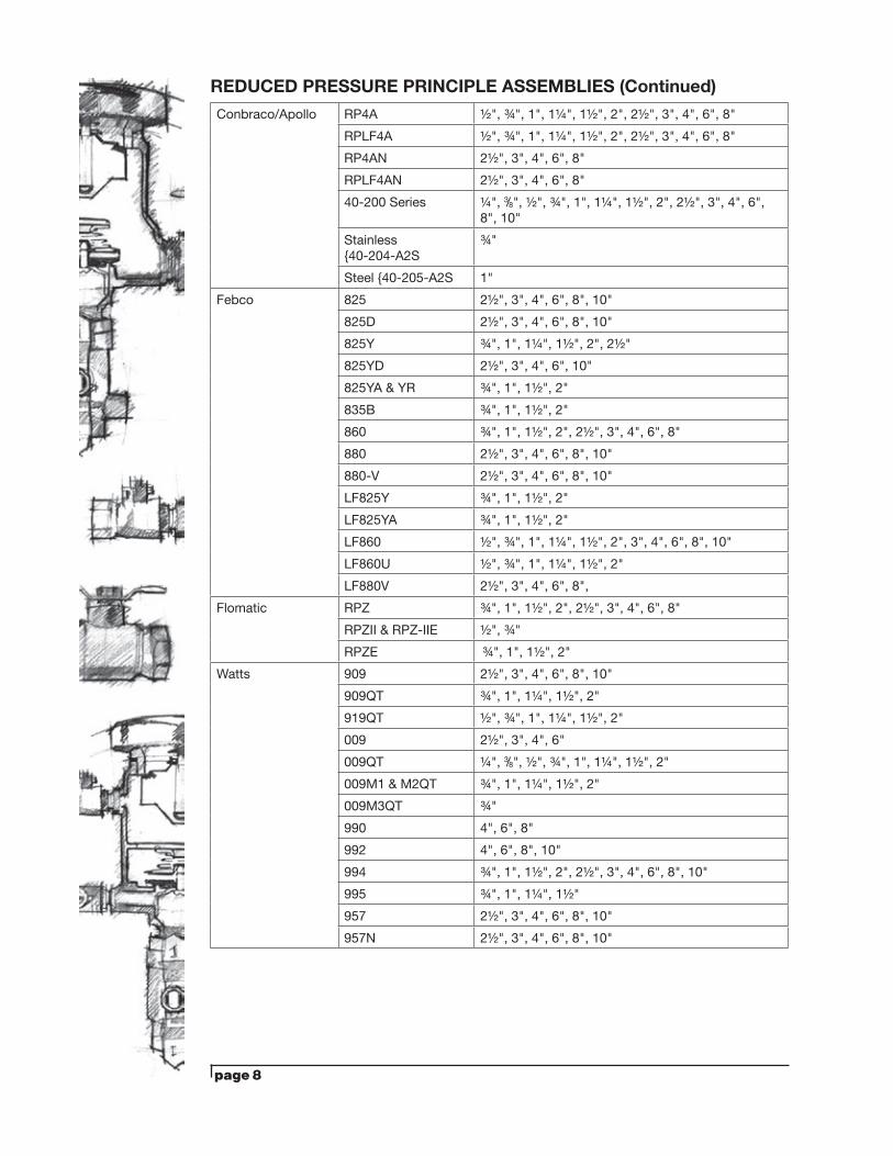
Conbraco/Apollo RP4A ½", ¾", 1", 1¼", 1½", 2", 2½", 3", 4", 6", 8"
RPLF4A ½", ¾", 1", 1¼", 1½", 2", 2½", 3", 4", 6", 8"
RP4AN 2½", 3", 4", 6", 8"
RPLF4AN 2½", 3", 4", 6", 8"
40-200 Series ¼", 3/8", ½", ¾", 1", 1¼", 1½", 2", 2½", 3", 4", 6", 8", 10"
Stainless {40-204-A2S
¾"
Steel {40-205-A2S 1"
Febco 825 2½", 3", 4", 6", 8", 10"
825D 2½", 3", 4", 6", 8", 10"
825Y ¾", 1", 1¼", 1½", 2", 2½"
825YD 2½", 3", 4", 6", 10"
825YA & YR ¾", 1", 1½", 2"
835B ¾", 1", 1½", 2"
860 ¾", 1", 1½", 2", 2½", 3", 4", 6", 8"
880 2½", 3", 4", 6", 8", 10"
880-V 2½", 3", 4", 6", 8", 10"
LF825Y ¾", 1", 1½", 2"
LF825YA ¾", 1", 1½", 2"
LF860 ½", ¾", 1", 1¼", 1½", 2", 3", 4", 6", 8", 10"
LF860U ½", ¾", 1", 1¼", 1½", 2"
LF880V 2½", 3", 4", 6", 8",
Flomatic RPZ ¾", 1", 1½", 2", 2½", 3", 4", 6", 8"
RPZII & RPZ-IIE ½", ¾"
RPZE ¾", 1", 1½", 2"
Watts 909 2½", 3", 4", 6", 8", 10"
909QT ¾", 1", 1¼", 1½", 2"
919QT ½", ¾", 1", 1¼", 1½", 2"
009 2½", 3", 4", 6"
009QT ¼", 3/8", ½", ¾", 1", 1¼", 1½", 2"
009M1 & M2QT ¾", 1", 1¼", 1½", 2"
009M3QT ¾"
990 4", 6", 8"
992 4", 6", 8", 10"
994 ¾", 1", 1½", 2", 2½", 3", 4", 6", 8", 10"
995 ¾", 1", 1¼", 1½"
957 2½", 3", 4", 6", 8", 10"
957N 2½", 3", 4", 6", 8", 10"
REDUCED PRESSURE PRINCIPLE ASSEMBLIES (Continued)
page 9
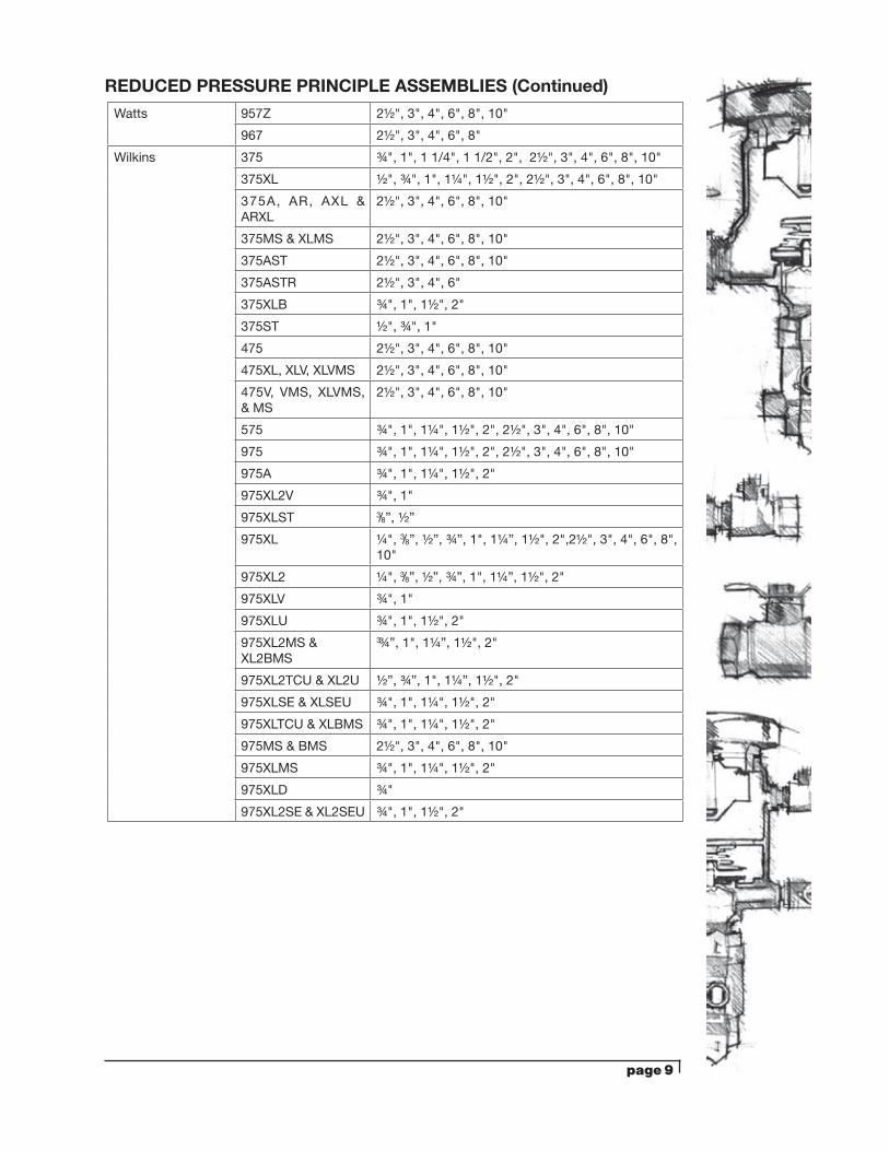
Watts 957Z 2½", 3", 4", 6", 8", 10"
967 2½", 3", 4", 6", 8"
Wilkins 375 ¾", 1", 1 1/4", 1 1/2", 2", 2½", 3", 4", 6", 8", 10"
375XL ½", ¾", 1", 1¼", 1½", 2", 2½", 3", 4", 6", 8", 10"
375A, AR, AXL & ARXL
2½", 3", 4", 6", 8", 10"
375MS & XLMS 2½", 3", 4", 6", 8", 10"
375AST 2½", 3", 4", 6", 8", 10"
375ASTR 2½", 3", 4", 6"
375XLB ¾", 1", 1½", 2"
375ST ½", ¾", 1"
475 2½", 3", 4", 6", 8", 10"
475XL, XLV, XLVMS 2½", 3", 4", 6", 8", 10"
475V, VMS, XLVMS, & MS
2½", 3", 4", 6", 8", 10"
575 ¾", 1", 1¼", 1½", 2", 2½", 3", 4", 6", 8", 10"
975 ¾", 1", 1¼", 1½", 2", 2½", 3", 4", 6", 8", 10"
975A ¾", 1", 1¼", 1½", 2"
975XL2V ¾", 1"
975XLST 3/8”, ½”
975XL ¼", 3/8”, ½”, ¾”, 1", 1¼”, 1½", 2",2½", 3", 4", 6", 8", 10"
975XL2 ¼", 3/8”, ½”, ¾”, 1", 1¼”, 1½", 2"
975XLV ¾", 1"
975XLU ¾", 1", 1½", 2"
975XL2MS & XL2BMS
3¾”, 1", 1¼”, 1½", 2"
975XL2TCU & XL2U ½”, ¾”, 1", 1¼”, 1½", 2"
975XLSE & XLSEU ¾", 1", 1¼", 1½", 2"
975XLTCU & XLBMS ¾", 1", 1¼", 1½", 2"
975MS & BMS 2½", 3", 4", 6", 8", 10"
975XLMS ¾", 1", 1¼", 1½", 2"
975XLD ¾"
975XL2SE & XL2SEU ¾", 1", 1½", 2"
REDUCED PRESSURE PRINCIPLE ASSEMBLIES (Continued)
page 10
DHEC LIST OF APPROVED BACKFLOW PREVENTION DEVICES
PRESSURE VACUUM BREAKERS
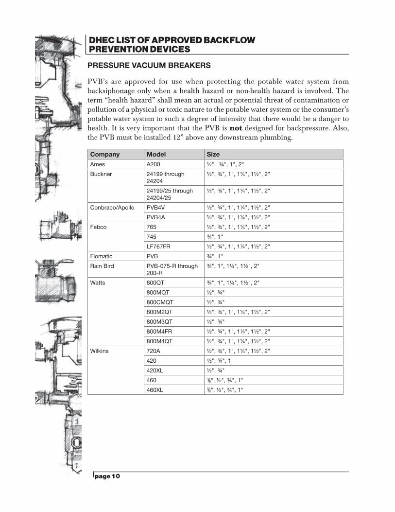
PVB’s are approved for use when protecting the potable water system from backsiphonage only when a health hazard or non-health hazard is involved. The term “health hazard” shall mean an actual or potential threat of contamination or pollution of a physical or toxic nature to the potable water system or the consumer’s potable water system to such a degree of intensity that there would be a danger to health. It is very important that the PVB is not designed for backpressure. Also, the PVB must be installed 12” above any downstream plumbing.
Company Model Size
Ames A200 ½", ¾", 1", 2"
Buckner 24199 through 24204
½", ¾", 1", 1¼", 1½", 2"
24199/25 through 24204/25
½", ¾", 1", 1¼", 1½", 2"
Conbraco/Apollo PVB4V ½", ¾", 1", 1¼", 1½", 2"
PVB4A ½", ¾", 1", 1¼", 1½", 2"
Febco 765 ½", ¾", 1", 1¼", 1½", 2"
745 ¾", 1"
LF767FR ½", ¾", 1", 1¼", 1½", 2"
Flomatic PVB ¾", 1"
Rain Bird PVB-075-R through 200-R
¾", 1", 1¼", 1½", 2"
Watts 800QT ¾", 1", 1¼", 1½", 2"
800MQT ½", ¾"
800CMQT ½", ¾"
800M2QT ½", ¾", 1", 1¼", 1½", 2"
800M3QT ½", ¾"
800M4FR ½", ¾", 1", 1¼", 1½", 2"
800M4QT ½", ¾", 1", 1¼", 1½", 2"
Wilkins 720A ½", ¾", 1", 1¼", 1½", 2"
420 ½", ¾", 1
420XL ½", ¾"
460 3/8", ½", ¾", 1"
460XL 3/8", ½", ¾", 1"
page 11
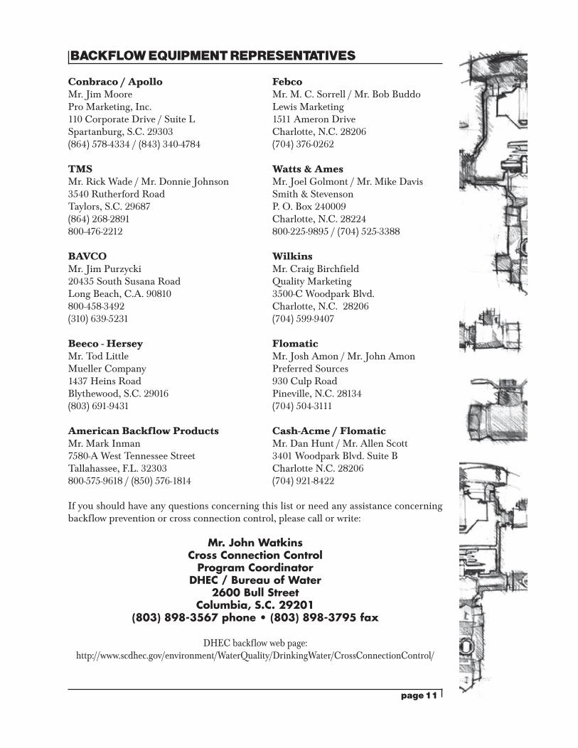
BACKFLOW EQUIPMENT REPRESENTATIVES
Conbraco / Apollo FebcoMr. Jim Moore Mr. M. C. Sorrell / Mr. Bob BuddoPro Marketing, Inc. Lewis Marketing110 Corporate Drive / Suite L 1511 Ameron DriveSpartanburg, S.C. 29303 Charlotte, N.C. 28206(864) 578-4334 / (843) 340-4784 (704) 376-0262
TMS Watts & AmesMr. Rick Wade / Mr. Donnie Johnson Mr. Joel Golmont / Mr. Mike Davis3540 Rutherford Road Smith & StevensonTaylors, S.C. 29687 P. O. Box 240009(864) 268-2891 Charlotte, N.C. 28224800-476-2212 800-225-9895 / (704) 525-3388
BAVCO WilkinsMr. Jim Purzycki Mr. Craig Birchfield20435 South Susana Road Quality MarketingLong Beach, C.A. 90810 3500-C Woodpark Blvd. 800-458-3492 Charlotte, N.C. 28206(310) 639-5231 (704) 599-9407
Beeco - Hersey FlomaticMr. Tod Little Mr. Josh Amon / Mr. John AmonMueller Company Preferred Sources1437 Heins Road 930 Culp RoadBlythewood, S.C. 29016 Pineville, N.C. 28134(803) 691-9431 (704) 504-3111
American Backflow Products Cash-Acme / FlomaticMr. Mark Inman Mr. Dan Hunt / Mr. Allen Scott7580-A West Tennessee Street 3401 Woodpark Blvd. Suite BTallahassee, F.L. 32303 Charlotte N.C. 28206800-575-9618 / (850) 576-1814 (704) 921-8422
If you should have any questions concerning this list or need any assistance concerning backflow prevention or cross connection control, please call or write:
Mr. John WatkinsCross Connection Control
Program CoordinatorDHEC / Bureau of Water
2600 Bull StreetColumbia, S.C. 29201
(803) 898-3567 phone • (803) 898-3795 fax
DHEC backflow web page: http://www.scdhec.gov/environment/WaterQuality/DrinkingWater/CrossConnectionControl/
page 12
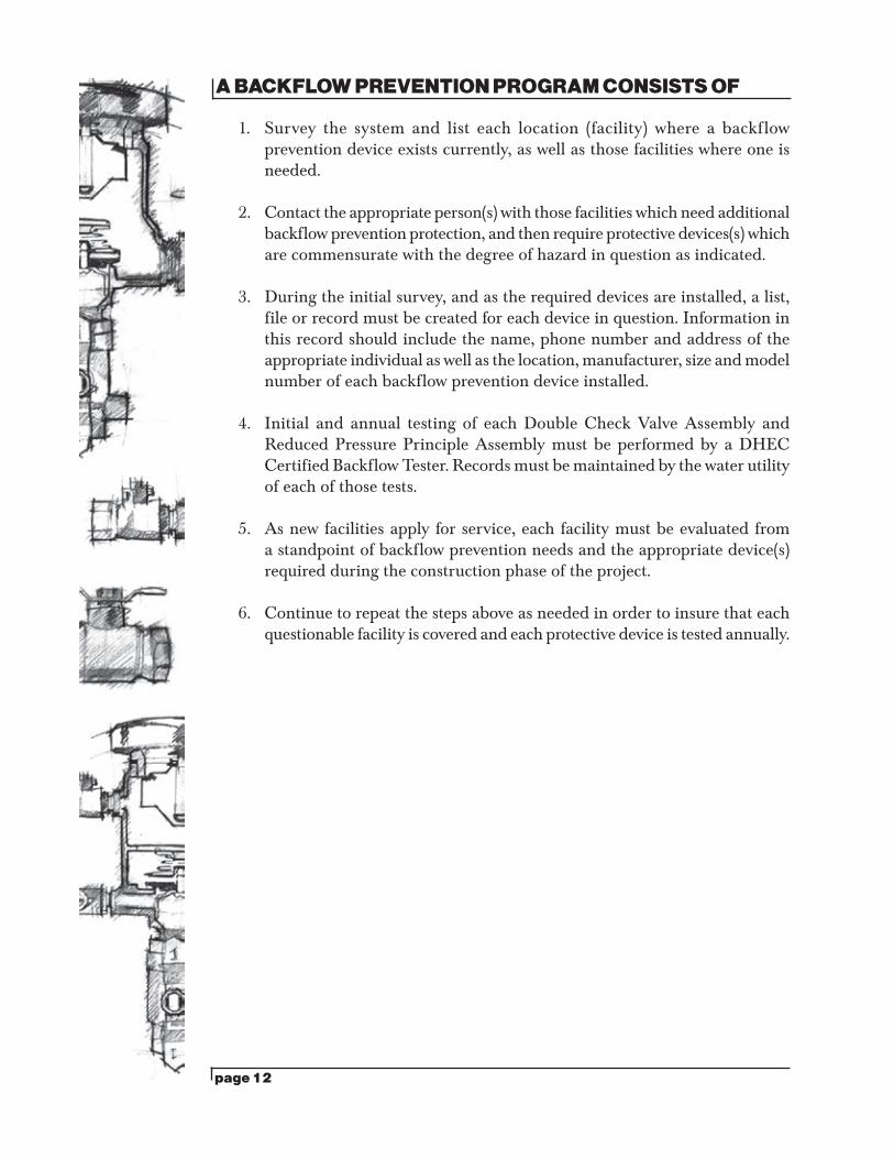
A BACKFLOW PREVENTION PROGRAM CONSISTS OF
1. Survey the system and list each location (facility) where a backflow prevention device exists currently, as well as those facilities where one is needed.
2. Contact the appropriate person(s) with those facilities which need additional backflow prevention protection, and then require protective devices(s) which are commensurate with the degree of hazard in question as indicated.
3. During the initial survey, and as the required devices are installed, a list, file or record must be created for each device in question. Information in this record should include the name, phone number and address of the appropriate individual as well as the location, manufacturer, size and model number of each backflow prevention device installed.
4. Initial and annual testing of each Double Check Valve Assembly and Reduced Pressure Principle Assembly must be performed by a DHEC Certified Backflow Tester. Records must be maintained by the water utility of each of those tests.
5. As new facilities apply for service, each facility must be evaluated from a standpoint of backflow prevention needs and the appropriate device(s) required during the construction phase of the project.
6. Continue to repeat the steps above as needed in order to insure that each questionable facility is covered and each protective device is tested annually.
page 13
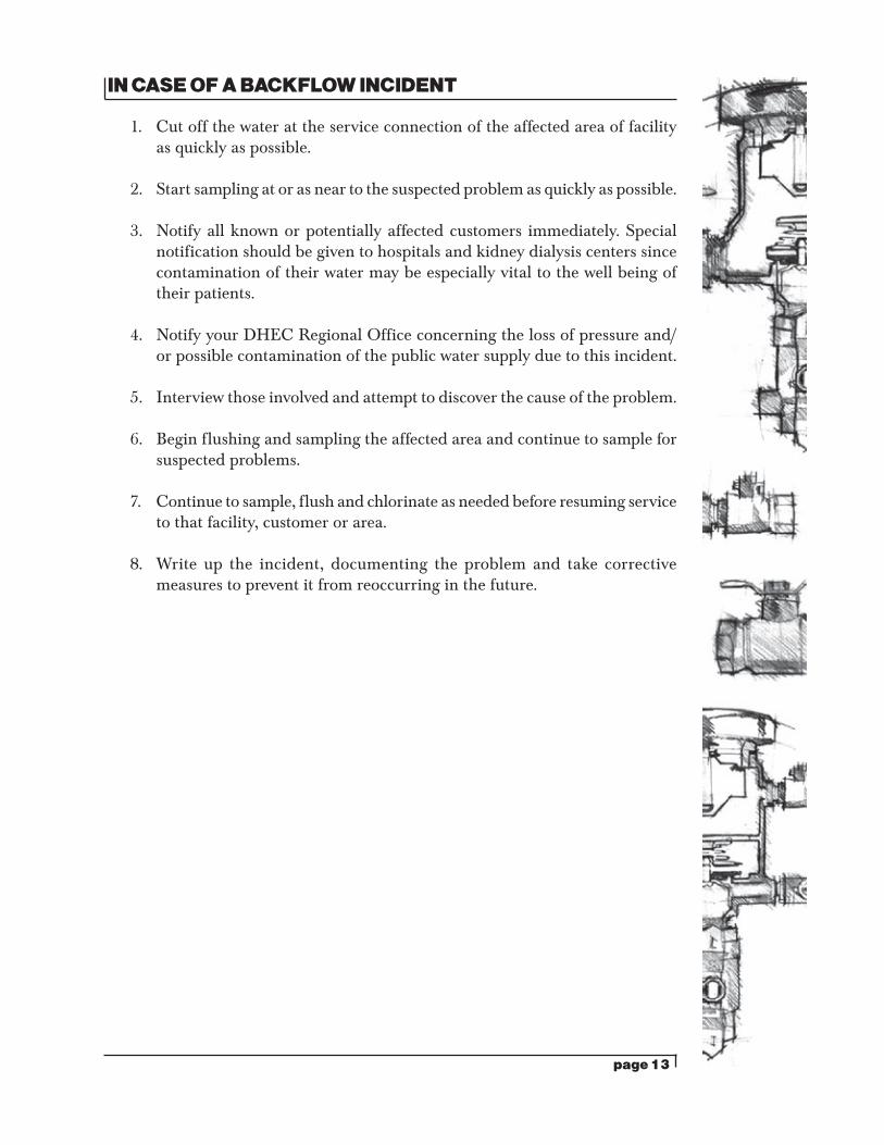
IN CASE OF A BACKFLOW INCIDENT
1. Cut off the water at the service connection of the affected area of facility as quickly as possible.
2. Start sampling at or as near to the suspected problem as quickly as possible.
3. Notify all known or potentially affected customers immediately. Special notification should be given to hospitals and kidney dialysis centers since contamination of their water may be especially vital to the well being of their patients.
4. Notify your DHEC Regional Office concerning the loss of pressure and/or possible contamination of the public water supply due to this incident.
5. Interview those involved and attempt to discover the cause of the problem.
6. Begin flushing and sampling the affected area and continue to sample for suspected problems.
7. Continue to sample, flush and chlorinate as needed before resuming service to that facility, customer or area.
8. Write up the incident, documenting the problem and take corrective measures to prevent it from reoccurring in the future.
page 14
DETERMINING BACKFLOW PROTECTION FOR VARIOUS FACILITIES
CHEMICAL PLANTS: Generally, such facilities fall into the high hazard category and are required to be protected by an AIR GAP or RP.
SEWAGE TREATMENT PLANTS: This facility is a high hazard application due to the fact that sewage may carry viruses, parasites, etc. This being the case, the water purveyor has only two options: AIR GAP or RP.
INDUSTRIAL ACCOUNTS: The degree of hazard should be assessed and protection required according to the degree of hazard found. Ideally, this process would occur during construction. Reduced Pressure Backflow Preventers are indicated for any industrial account unless considerable internal protective measures have been taken, or the determination can be made that no real hazard exists within the facility.
FUNERAL HOMES: Any funeral home or morgue which utilizes the hydro aspirator is required to install the RP. Those facilities which utilize the Pierce Water Control Unit or an electric vacuum pump may be down graded (with the water purveyor’s permission) to a DCVA. When a DCVA is allowed due to the lowered hazard as described above then the device should be installed as close to the meter or service connection as possible. However, when an RP is required, it may be installed in or near the preparation room in order to isolate the hazard from the rest of the facility.
HOSPITALS: There are so many areas within a hospital that would be considered a high hazard application, the water purveyor has only two options for protection: AIR GAP or RP. In most cases a hospital falls into the category of a customer that will always need water continuous in an uninterrupted demand. With this becoming a problem, a dual or parallel set of RPs should be required, unless there is a second meter feeding this facility that also has a RP installed.
DENTIST, DOCTOR, VETERINARIAN, CHIROPRACTOR, ETC: These facilities often do not offer the degree of hazard which their names would imply. In most cases, a Double Check Valve Assembly will offer adequate protection. However, if an internal inspection is conducted and internal protection is provided, then a Residential Dual Check may be acceptable. Usually x-ray development is the most frequent cross connection found in these facilities.
page 15
DETERMINING BACKFLOW PROTECTION FOR VARIOUS FACILITIES (Continued)
CAR WASHES: Self-service (coin operated) or small quick drive through car washes must be protected with DCVAs. This device may be installed either in the supply line at the meter or as the line enters the equipment room. The larger, totally self-service type, or any type where a recirculation pump is employed, must be protected via a RP. The RP may be installed at the meter or at a key location within the facility to isolate the process from the drinking water fountain, coffee pot, etc.
PUBLIC SWIMMING POOLS: DHEC has regulations which govern the construction, maintenance and operation of public swimming pools. Such facilities are required to be filled through an AIR GAP. However if the below-the-rim fills are used then an approved DCVA should have been required during the construction phase. If your inspection of a public swimming pool reveals no protection, then an approved DCVA must be installed.
RESTAURANTS: Assuming that appropriate protective devices have been installed internally, DCVAs offer good protection for restaurants. If you are attempting to reduce the number of testable devices, then Residential Dual Checks could be allowed on small restaurants with 3/4" supply lines. Restaurants are subjected to a number of other inspections internally, some of which address the need to have adequate backflow prevention protection within. While this may allow you to lessen the requirement at the meter, it cannot usually be used as an excuse to avoid protection of any kind at the meter.
LAUNDROMATS: New laundromats must be protected with DCVAs. However, if the water purveyor is desirous, arrangements can be made on existing laundromats to “grandfather” them in. If the owner will remove one or more of the tops or back panels of the machines and if each machine is protected by some type of factory installed or credible backflow prevention device, then those laundromats may be left as is until some future upgrade or ownership change occurs. These decisions must be made locally.
DRY CLEANERS: New dry cleaning establishments (not pick up stations) should be protected with RP devices unless internal protective devices have been installed in strategic locations within the facility.
PRIVATE (RESIDENTIAL) SWIMMING POOLS: Almost without exception, residential swimming pools are filled through a hose bibb. Protection either at the hose bibb or at the meter via a Residential Dual Check should offer adequate protection.
page 16
PUBLIC SCHOOLS: High schools usually require RPs either on the supply line or within the facility at strategic locations. Places of concern are: chemistry/biology laboratories, lawn irrigation on the ball field, boilers, heating and cooling equipment rooms, cafeteria kitchens and film developing rooms. Look for the same hazards in middle, intermediate and elementary schools and address them as needed. In most cases, a DCVA would offer adequate protection for these types of schools since there are usually no laboratories to be concerned with.
BEAUTY/BARBER SALONS: The source of concern in these facilities is the possibility of the shower/spray head being submerged in water tainted with shampoos or other chemicals common to these facilities. Vacuum breakers at each sink, as well as other offending outlets, and a Residential Dual Check at the meter will normally offer adequate protection. In the cases of small, one or two chair facilities, a Residential Dual Check at the meter should offer adequate protection. In some instances where the facilities in question are large, busy and in a populated area, a DCVA would be indicated. Again these decisions must be made locally, depending on many different factors.
FIRE LINE SPRINKLER SYSTEMS: Simple fire line sprinkler systems must be protected with a minimum of an approved Double Check Valve Assembly. Single checks do not offer adequate protection and are not recognized where a known or suspected hazard exists. Systems with auxiliary storage and/or booster pumps should still be allowed to be protected with DCVAs, as long as the storage is covered and maintained and the water filling the tank was taken from a potable system.
Fire sprinkler systems where greater hazards exist should be protected with approved Reduced Pressure Backflow Preventers. This would include, but not be limited to antifreeze systems, foam injection systems, systems charged from or tied into ponds, lakes, streams or any water source other than the approved public supply. Remember that RP devices cannot be installed in a pit unless it is drained by gravity to the surface of the ground. RP devices cannot usually be installed in the vertical position and they reduce as much as 14 psi of system pressure. For these reasons, it should be understood that RP devices should be installed as a last resort. Use them if you must, but do not over use them!
Dry type fire protection systems are as potentially hazardous as a simple wet system. The reason is that these systems are charged with water periodically for testing and some water stays in the lines. Also, condensation occurs in the lines from the air compressor and the result is a concentration of very rusty water, which offers the threat that a simple wet systems offers. With power failure to the air compressor, the potential of this dry system becoming a wet system can occur. Therefore, DCVAs must be required on dry type systems.
This list is not a regulation, but reflects the application of regulations in systems across the state. This list is meant to be used as a guideline only and is designed to assist water purveyors, plumbers, contractors, etc. in the decision making process.
page 17
BACKFLOW PREVENTION ASSEMBLYTEST KIT INFORMATION
In an attempt to answer a question which is frequently asked, the following is information pertaining to the purchase of a good test kit for a reasonable price.
1. Conbraco / Apollo backflow Prevention Device Test Kit(s) Model 40-20TK or 40-200TK5: The 40-200TK is their three valve differential gauge. The 40-200TK5 is their five valve differential gauge. Both gauges are very reliable and durable for testing DCVA’s, PVB’s, and RPPA’s. For Information on purchasing these test kits please call Pro Marketing in Spartanburg, S.C. at (864) 578-4334. They will give you the names of their suppliers in your area that sell these differential gauges.
2. Mid West Backflow Prevention Device Test Kit Model 830: This device is a very old and reliable test kit. They offer a re-calibration service agreement in which they will calibrate the test kit for a nominal fee. If any repair is required, the owner will be given an estimate of that cost. You may obtain this differential gauge through Specialty Valve & Control Company in Charlotte, N.C. at (704) 522-9873. Other quality Mid West differential gauges that can be purchased are, Model#: 835-5 valve, 845-3 valve, and 845-5 valve. These Mid West differential gauges are very popular.
3. Watts Backflow Prevention Device Test Kit Model TK-99E: This differential gauge has been on the market for many years. It is a five valve differential gauge with a high degree of accuracy. It is equipped with a small gauge attached to the side of the regular gauge for the purpose of monitoring the incoming or supply side pressure. For information on purchasing this differential gauge or other Watts gauges please call Smith & Stevenson in Charlotte, N.C. at 800-225-9895. They will give you the names of their suppliers in your area that sell this differential gauge. Other quality Watts differential gauges that can be purchased are, Model#: TK99D, TKDP, and TKDR.
4. Other common differential gauges purchased to test DCVA’s and RPPA’s in SC:
A. Febco RPTK 1 call SPC Marketing at (704) 283-8554.B. ITT Barton 247 call Bavco at 800-458-3492.C. Pro Master ASRP4 call Astra Industrial Services Inc
at 800-776- 1464.D. Wilkins BFTG, BFTG 5 or TK-150 call Quality Marketing
at (704) 599-9407.
page 18
BACKFLOW PREVENTION TESTING TIPS
1. When you approach a RP device and it is leaking, or if it starts leaking after you close the second shut off valve, there is no reason to attempt to test the device.
If you have clearance and/or permission from the appropriate person(s) go into the device and perform the necessary repairs. If not, inform the responsible person that the device is malfunctioning. Inform him that the device must be cleaned or repaired before a satisfactory test can be performed.
2. When testing the RP device, if the second shut-off valve is leaking, you will not be able to perform an accurate test on the second check or the relief valve.
When you are testing the second check valve you are injecting water into test cock # 4 in order to put back pressure on the check valve. If the second shut off valve is leaking more than the amount of water being piped into test cock #4, then you would not be able to build up any back pressure against the second check. This problem may be overcome by transferring water from test cock # 1 into test cock #4. A “tee” adaptor will be necessary at test cock #4 in order to accomplish this task.
A similar problem will result when attempting to test the relief valve. As you pipe water into test cock #3 in an attempt to build up the pressure in the zone in order to record the relief valve opening pressure, the water injected will simply proceed down stream through the second check and leaking second shut-off valve. This will most likely result in the relief valve failing to open! This problem may be alleviated as mentioned above by piping water into test cock #4.
3. When testing the RP relief valve, if the Differential Gauge falls below 2.0 psid before the relief valve opens, the most likely causes are:
A. A gauge which is out of calibration.B. Guide or diaphragm problems in the relief valve.C. A cocked, binding or weak spring in the relief valve.
Be mindful that you will not always be able to apply simple charts or “tips” to solve these problems.
page 19
DOUBLE CHECK VALVE ASSEMBLY TEST
VERTICAL TUBE
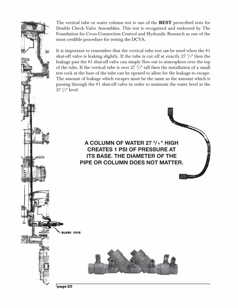
This testing procedure takes advantage of the fact that 1 psi of pressure is created at the base of a 27 3/4" high water column. The tricky part of this test is that the pressure is applied on the up-stream (or supply) side of the check valve and in direction of flow rather than as back pressure.
A big advantage of this test is that it may be performed on assemblies which have a missing #1 test cock or which may have a leaking #1 shut off valve. A moderate amount of leakage past the first shut off valve can be tolerated since that leakage will simply spill out the top of the 27 3/4" water column. Also, a small test cock may be installed at the base of the water column which may be opened to allow the appropriate amount of water to spill out, maintaining the 27 3/4" level in the water column.
TEST PROCEDURE:CHECK VALVE #1
1. Open and close all test cocks individually to flush out any sediment or scale.2. Install vertical tube onto test cock #2.3. Open test cock #2 and allow water to fill the tube (a column of water 27 3/4" high
creates 1 psi of pressure at its base). When the 27 3/4" tube is filled, close test cock #2.
4. Close shut off valve #1 and #2.5. Open test cock #3 first; then open #2 (position the base of the tube at the same
level as test cock #3). Some leakage will occur from test cock #3 as water escapes from the body of the valve. However, if leakage continues to occur, water is passing through check valve #1, indicating a failure of check valve #1.
*Note: Leakage out of test cock #3 should be accompanied by a fall in the water level of the vertical tube, unless shut-off valve #1 is leaking enough to keep the vertical tube full and/or over flowing.
CHECK VALVE #2 1. Close test cocks #2 and #3.2. Remove the vertical tube from test cock #2 and install it onto test cock #3.3. Open shut-off valve #1 and test cock #3 in order to fill the vertical tube to the
27 3/4" level.4. Close test cock #3 and shut-off valve #1.5. Open test cock #4 first, then open test cock #3 (position the base of the tube at
the same level as test cock #4). Some leakage will occur from test cock #4 as water drains from the body of the valve. If leakage continues to occur, water is passing through check valve #2, indicating a failure of check valve #2.
*Note: Leakage out of test cock #4 should be accompanied by a fall in the water level of the vertical tube, unless shut-off valve #1 is leaking enough to keep the vertical tube full and/or over flowing.
6. Close all test cocks and open all shut-off valves before leaving the assembly.
page 20
The vertical tube or water column test is one of the BEST prescribed tests for Double Check Valve Assemblies. This test is recognized and endorsed by The Foundation for Cross Connection Control and Hydraulic Research as one of the most credible procedure for testing the DCVA.
It is important to remember that the vertical tube test can be used when the #1 shut-off valve is leaking slightly. If the tube is cut off at exactly 27 3/4" then the leakage past the #1 shut-off valve can simply flow out to atmosphere over the top of the tube. If the vertical tube is over 27 3/4" tall then the installation of a small test cock at the base of the tube can be opened to allow for the leakage to escape. The amount of leakage which escapes must be the same as the amount which is passing through the #1 shut-off valve in order to maintain the water level at the 27 3/4" level.
A COLUMN OF WATER 27 3/ 4 " HIGH CREATES 1 PSI OF PRESSURE AT ITS BASE. THE DIAMETER OF THE
PIPE OR COLUMN DOES NOT MATTER.
page 21
DCVA/DIFFERENTIAL 3 VALVE GAUGE (DIRECTION OF FLOW)
IMPORTANT: Since the gauge and low hose must be held at the same level as the DCVA and since many small DCVAs are installed in meter boxes with very close side clearances, this test may not be acceptable in such instances. If so, you may substitute the vertical tube test. The theory and practice are similar on these two tests.
TEST PROCEDURECHECK VALVE #1
1. Close all valves on test kit.2. Attach high hose of gauge to test cock #2.3. Slowly open test cock #2.4. Open high “A” and vent “C” on test kit and bleed air from kit.5. Close vent “C” valve on gauge after air is expelled.6. Close shut-off valve #2 then #1. With both shut-off valves now closed some
pressure is trapped inside of the DCVA.7. Open test cock #3. Test cock #2 should still be open.8. At this point, the gauge needle must not drop below 1.0 psi. 9. If the gauge needle holds at 1.0 psi or greater then the check valve is holding tight.
CHECK VALVE #21. Close test cocks #2 and #3 on the DCVA and close high “A” and vent “C” on the
test kit.2. Move the high hose from test cock #2 to test cock #3. 3. Open shut-off valve #1 on the DCVA.4. Slowly open test cock #3 on DCVA.5. Open high “A” and vent “C” valves to bleed air from the kit. 6. Close vent “C” valve on gauge after air is expelled.7. Close shut-off valve #1 on the DCVA. Pressure now trapped inside of the DCVA.8. Open test cock #4. Test cock #3 should still be open.9. If the gauge needle holds at 1.0 psi or greater then the check valve is holding tight.
IN CLOSING
1. Close all test cocks on DCVA.2. Open customer hose bibb for flushing if possible.3. Slowly open both shut-off valves on DCVA.4. Allow water to flow for a minute from the open hose bibb. 5. Close hose bibb.6. Check with customer, flush a toilet and/or run some water within the facility if
possible before leaving.
All valves on the test kit should be opened and the kit allowed to drain prior to storage. This is especially important during cold weather due to the danger of freezing.
*Note: The above testing procedure is conducted with the #1 shut-off valve in the closed position. This means that the #1 shut-off valve must not leak. Open test cock #2 and inspect for continuous leakage. If #1 shut-off valve is leaking then you cannot use this test. However, the DCVAs where small leakage occurs past time the #1 shut-off valve.
page 22
DCVA/DIFFERENTIAL 5 VALVE GAUGE (DIRECTION OF FLOW)
IMPORTANT: Since the gauge and low hose must be held at the same level as the DCVA and since many small DCVAs are installed in meter boxes with very close side clearances, this test may not be acceptable in such instances. If so, you may substitute the vertical tube test. The theory and practice are similar on these two tests.
TEST PROCEDURECHECK VALVE #1
1. Close all five valves on test kit.2. Attach high hose of gauge to test cock #2.3. Slowly open test cock #2.4. Open high bleed valve on test kit and bleed air from kit.5. Close high bleed valve after air is expelled.6. Close shut-off valve #2 then #1. With both shut-off valves now closed pressure is
trapped inside of the DCVA.7. Open test cock #3. Test cock #2 should still be open.8. At this point, the gauge needle must not drop below 1.0 psi.9. If the gauge needle holds at 1.0 psi or greater, the check valve is holding tight.
CHECK VALVE #21. Close test cocks #2 and 3 on the DCVA and close the high bleed valve on the test kit.2. Move the high hose from test cock #2 to test cock #3.3. Open shut-off valve #1.4. Slowly open test cock #3.5. Open high bleed valve on test kit and bleed air from kit.6. Close high bleed valve after air is expelled.7. Close shut-off valve #1. Pressure is trapped inside of the DCVA.8. Open test cock #4. Test cock #3 should still be open.9. If the gauge needle holds at 1.0 psi or greater, the check valve is holding tight.
IN CLOSING
1. Close all test cocks, remove hoses, and brass fittings.2. Open customer hose bibb for flushing if possible.3. Slowly open both shut-off valves on DCVA.4. Allow water to flow for a minute from the open hose bibb.5. Close hose bibb.6. Check with customer, flush a toilet, and/or run some water within the facility if
possible before leaving.
All valves on the test kit should be opened and the kit allowed to drain prior to storage. This is especially important during cold weather due to the danger of freezing.
*Note: The above testing procedure is conducted with the #1 shut-off valve in the closed position. This means that the #1 shut-off valve must not leak. Open test cock #2 and inspect for continuous leakage. If #1 shut-off valve is leaking then you cannot use this test. However, the Vertical Tube or Differential Pressure Test can be used on DCVAs where small leakage occurs past the #1 shut-off valve.
page 23
DCVA/DIFFERENTIAL 3 VALVE GAUGE (DIFFERENTIAL PRESSURE TEST)
(Performed with the first shut-off valve open)
This test is performed with the Differential Pressure Gauge Test Kit. As you will recall from the RP test, the Differential Pressure Gauge simply measures the pressure drop across the check valve. This pressure drop is normally the same as the strength of the check valve spring. In using the Differential Pressure Gauge to test the Double Check Valve Assembly, a minimum of 1.0 psid is required for each check valve in order for that check valve to pass the test. Such a small reading is often difficult to read on most test kits. This is one of the drawbacks of this test. However, since the first shut-off valve is left in the open position for this test, it is possible to use this test when the first shut-off valve is leaking badly.
TEST PROCEDUREPREP WORK
1. Notify customer that the water service will be off. Identify the make, model and serial number on the backflow device. Inspect that this is an approved assembly- 2-check valves, 2-shutoff valves, 4-test cocks. Observe the area to make sure there are no leaks.
2. Flush test cocks (1, 2, 3 and 4), then close all test cocks.3. Install brass fittings in the test cocks.4. Close shut-off valve #2.
CHECK VALVE #11. Close all valves on test kit.2. Connect the high side hose to test cock #2 and the low side hose to test cock #3.
Open test cock #2 and test cock #3.3. Open vent valve “C” and high “A” on the test kit to bleed the air from the high
side of the kit. Close high “A” valve and then open low “B” valve to bleed the low side. Close low “B” valve.
4. Record the gauge reading. It must be a minimum of 1.0 psid in order to pass. Close test cock #2 and test cock #3.
CHECK VALVE #21. Move the high side hose to test cock #3 and the low side hose to test cock #4.
Open test cock #3 and test cock #4.2. Open vent “C” valve. Then open high “A” and bleed air from the high side of
kit. Close high “A” valve and then open low “B” valve and bleed the low side of kit. Close low “B” valve.
3. Record the gauge reading. It must be a minimum of 1.0 psid in order to pass. Close test cock #3 and test cock # 4. Remove hoses and test kit. Slowly open shut-off valve #2 in order to restore water flow to the facility, placing the DCVA back into service.
page 24
LEAKING #2 SHUT-OFF VALVE As previously mentioned, the above test is not accurate when the second shut-off valve is leaking. The following test will expose a leaking shut-off valve.
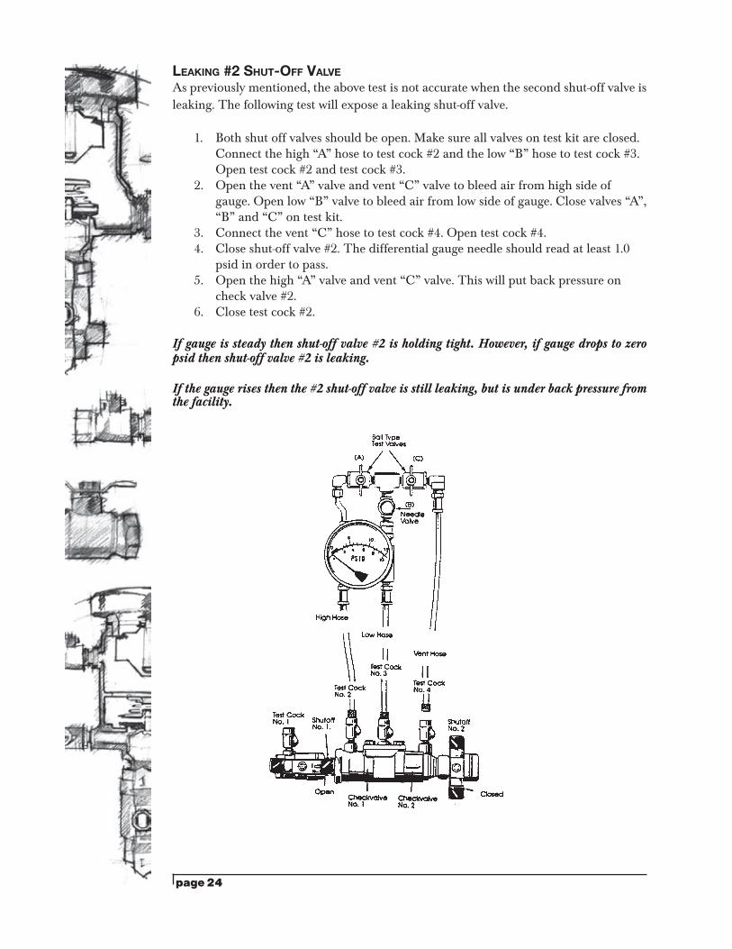
1. Both shut off valves should be open. Make sure all valves on test kit are closed. Connect the high “A” hose to test cock #2 and the low “B” hose to test cock #3. Open test cock #2 and test cock #3.
2. Open the vent “A” valve and vent “C” valve to bleed air from high side of gauge. Open low “B” valve to bleed air from low side of gauge. Close valves “A”, “B” and “C” on test kit.
3. Connect the vent “C” hose to test cock #4. Open test cock #4. 4. Close shut-off valve #2. The differential gauge needle should read at least 1.0
psid in order to pass.5. Open the high “A” valve and vent “C” valve. This will put back pressure on
check valve #2. 6. Close test cock #2.
If gauge is steady then shut-off valve #2 is holding tight. However, if gauge drops to zero psid then shut-off valve #2 is leaking.
If the gauge rises then the #2 shut-off valve is still leaking, but is under back pressure from the facility.
page 25
DCVA/DIFFERENTIAL 5 VALVE GAUGE (DIFFERENTIAL PRESSURE TEST)
(Performed with the first shut-off valve open)
This test is performed with the Differential Pressure Gauge Test Kit. As you will recall from the RP test, the Differential Pressure Gauge simply measures the pressure drop across the check valve. This pressure drop is normally the same as the strength of the check valve spring. In using the Differential Pressure Gauge to test the Double Check Valve Assembly, a minimum of 1.0 psid is required for each check valve in order for that check valve to pass the test. Such a small reading is often difficult to read on most test kits. This is one of the drawbacks of this test. However, since the first shut-off valve is left in the open position for this test, it is possible to use this test when the first shut-off valve is leaking badly.
TEST PROCEDUREPREP WORK
1. Notify customer that the water service will be off. Identify the make, model and serial number on the backflow device. Inspect that this is an approved assembly- 2-check valves, 2-shut-off valves, 4-test cocks. Observe the area to make sure there are no leaks.
2. Flush test cocks (1, 2, 3 and 4), then close all test cocks.3. Install brass fittings in the test cocks.4. Close shut-off valve #2.
CHECK VALVE #11. Close all valves on test kit.2. Connect the high side hose to test cock #2, and the low side hose to test cock #3.
Open test cock #2 and test cock #3.3. Open the low bleed valve and then the high bleed valve. This will expel all air
from gauge. Close high bleed valve, then low bleed valve.4. Record the gauge reading. It must be at least 1.0 psid in order to pass.
Close test cock #2 and #3.
CHECK VALVE #21. Move the high hose to test cock #3, and the low hose to test cock #4. Open test
cock #3 and test cock #4.2. Open the low bleed valve and then the high bleed valve. This will expel all air from gauge. Close high bleed valve, then low bleed valve.3. Record the gauge reading. It must be at least 1.0 psid in order to pass.
Close test cock #3 and #4. Remove hoses, brass fittings and test kit. Slowly open shut-off valve #2 in order to restore water flow to the facility, placing the DCVA back into service.
page 26
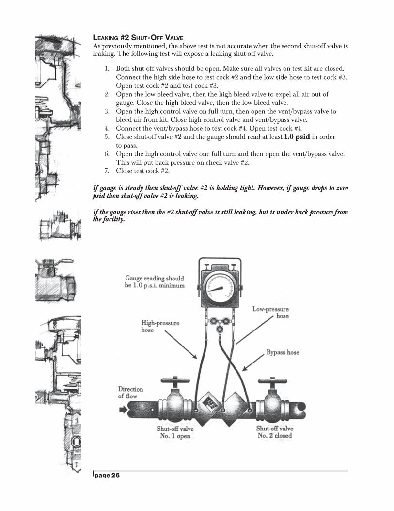
LEAKING #2 SHUT-OFF VALVE As previously mentioned, the above test is not accurate when the second shut-off valve is leaking. The following test will expose a leaking shut-off valve.
1. Both shut off valves should be open. Make sure all valves on test kit are closed. Connect the high side hose to test cock #2 and the low side hose to test cock #3. Open test cock #2 and test cock #3.
2. Open the low bleed valve, then the high bleed valve to expel all air out of gauge. Close the high bleed valve, then the low bleed valve.
3. Open the high control valve on full turn, then open the vent/bypass valve to bleed air from kit. Close high control valve and vent/bypass valve.
4. Connect the vent/bypass hose to test cock #4. Open test cock #4.5. Close shut-off valve #2 and the gauge should read at least 1.0 psid in order
to pass.6. Open the high control valve one full turn and then open the vent/bypass valve.
This will put back pressure on check valve #2. 7. Close test cock #2.
If gauge is steady then shut-off valve #2 is holding tight. However, if gauge drops to zero psid then shut-off valve #2 is leaking.
If the gauge rises then the #2 shut-off valve is still leaking, but is under back pressure from the facility.
page 27
PVB/DIFFERENTIAL 3 VALVE GAUGE (DIRECTION OF FLOW)
TesT seT UpNotify customer water will be off; inspect device for leaks; verify the make, model and serial number.
Flush test cocks and install brass fittings. REMOVE CANOPY.
Close valves “A,” “B,” “C,” on test kit and close the #2 shut-off valve.
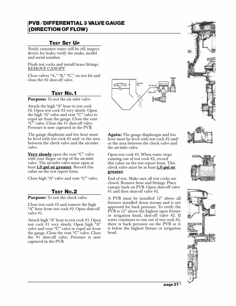
TesT No.1Purpose: To test the air inlet valve.
Attach the high “A” hose to test cock #2. Open test cock #2 very slowly. Open the high “A” valve and vent “C” valve to expel air from the gauge. Close the vent “C” valve. Close the #1 shut-off valve. Pressure is now captured in the PVB.
The gauge diaphram and low hose must be level with test cock #2 and/ or the area between the check valve and the air-inlet valve.
Very slowly open the vent “C” valve with your finger on top of the air-inlet valve. The air-inlet valve must open at least 1.0 psi or greater. Record this value on the test report form.
Close high “A” valve and vent “C” valve.
TesT No.2Purpose: To test the check valve.
Close test cock #2 and remove the high “A” hose from test cock #2. Open shut-off valve #1.
Attach high “A” hose to test cock #1. Open test cock #1 very slowly. Open high “A” valve and vent “C” valve to expel air from the gauge. Close the vent “C” valve. Close the #1 shut-off valve. Pressure is now captured in the PVB.
Again: The gauge diaphragm and low hose must be level with test cock #2 and/ or the area between the check valve and the air-inlet valve.
Open test cock #2. When water stops running out of test cock #2, record this value on the test report form. This check valve must be at least 1.0 psi or greater.
End of test. Make sure all test cocks are closed. Remove hose and fittings. Place canopy back on PVB. Open shut-off valve #1 and then shut-off valve #2.
A PVB must be installed 12” above all fixtures installed down stream and is not approved for back pressure. To verify the PVB is 12” above the highest open fixture or irrigation head, shut-off valve #2. If water continues to run out of test cock #2, there is back pressure on the PVB or it is below the highest fixture or irrigation head.
page 28
PVB/DIFFERENTIAL 5 VALVE GAUGE (DIRECTION OF FLOW)
TesT seT UpNotify customer water will be off; inspect device for leaks; verify the make, model and serial number.
Flush test cocks and install brass fittings. REMOVE CANOPY.
Close all five valves on test kit, and close the #2 shut-off valve.
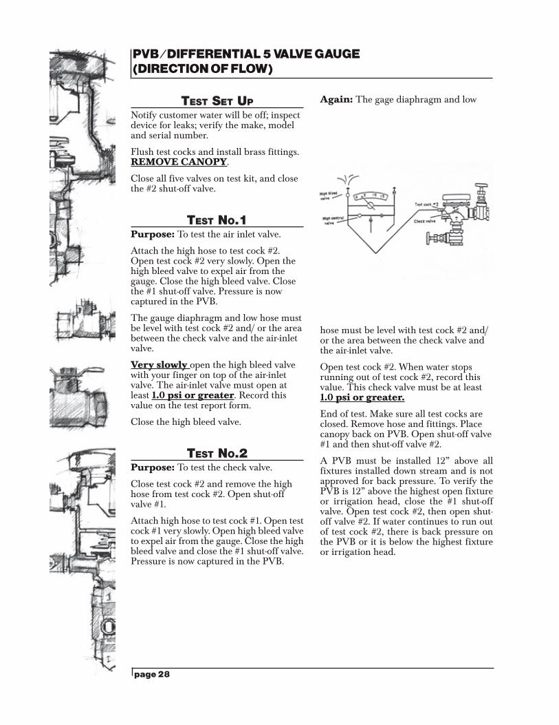
TesT No.1Purpose: To test the air inlet valve.
Attach the high hose to test cock #2. Open test cock #2 very slowly. Open the high bleed valve to expel air from the gauge. Close the high bleed valve. Close the #1 shut-off valve. Pressure is now captured in the PVB.
The gauge diaphragm and low hose must be level with test cock #2 and/ or the area between the check valve and the air-inlet valve.
Very slowly open the high bleed valve with your finger on top of the air-inlet valve. The air-inlet valve must open at least 1.0 psi or greater. Record this value on the test report form.
Close the high bleed valve.
TesT No.2Purpose: To test the check valve.
Close test cock #2 and remove the high hose from test cock #2. Open shut-off valve #1.
Attach high hose to test cock #1. Open test cock #1 very slowly. Open high bleed valve to expel air from the gauge. Close the high bleed valve and close the #1 shut-off valve. Pressure is now captured in the PVB.
Again: The gage diaphragm and low
hose must be level with test cock #2 and/ or the area between the check valve and the air-inlet valve.
Open test cock #2. When water stops running out of test cock #2, record this value. This check valve must be at least 1.0 psi or greater.
End of test. Make sure all test cocks are closed. Remove hose and fittings. Place canopy back on PVB. Open shut-off valve #1 and then shut-off valve #2.
A PVB must be installed 12” above all fixtures installed down stream and is not approved for back pressure. To verify the PVB is 12” above the highest open fixture or irrigation head, close the #1 shut-off valve. Open test cock #2, then open shut-off valve #2. If water continues to run out of test cock #2, there is back pressure on the PVB or it is below the highest fixture or irrigation head.
page 29
RPPA/DIFFERENTIAL 3 VALVE GAUGE (DIFFERENTIAL PRESSURE TEST)
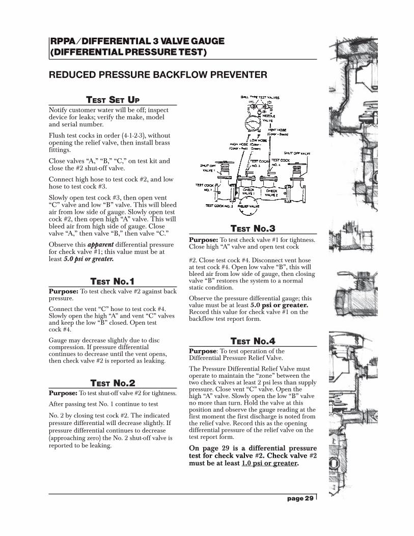
REDUCED PRESSURE BACKFLOW PREVENTER
TesT seT UpNotify customer water will be off; inspect device for leaks; verify the make, model and serial number.
Flush test cocks in order (4-1-2-3), without opening the relief valve, then install brass fittings.
Close valves “A,” “B,” “C,” on test kit and close the #2 shut-off valve.
Connect high hose to test cock #2, and low hose to test cock #3.
Slowly open test cock #3, then open vent “C” valve and low “B” valve. This will bleed air from low side of gauge. Slowly open test cock #2, then open high “A” valve. This will bleed air from high side of gauge. Close valve “A,” then valve “B,” then valve “C.”
Observe this apparent differential pressure for check valve #1; this value must be at least 5.0 psi or greater.
TesT No.1Purpose: To test check valve #2 against back pressure.
Connect the vent “C” hose to test cock #4. Slowly open the high “A” and vent “C” valves and keep the low “B” closed. Open test cock #4.
Gauge may decrease slightly due to disc compression. If pressure differential continues to decrease until the vent opens, then check valve #2 is reported as leaking.
TesT No.2Purpose: To test shut-off valve #2 for tightness.
After passing test No. 1 continue to test
No. 2 by closing test cock #2. The indicated pressure differential will decrease slightly. If pressure differential continues to decrease (approaching zero) the No. 2 shut-off valve is reported to be leaking.
TesT No.3 Purpose: To test check valve #1 for tightness. Close high “A” valve and open test cock
#2. Close test cock #4. Disconnect vent hose at test cock #4. Open low valve “B”, this will bleed air from low side of gauge, then closing valve “B” restores the system to a normal static condition.
Observe the pressure differential gauge; this value must be at least 5.0 psi or greater. Record this value for check valve #1 on the backflow test report form.
TesT No.4Purpose: To test operation of the Differential Pressure Relief Valve.
The Pressure Differential Relief Valve must operate to maintain the “zone” between the two check valves at least 2 psi less than supply pressure. Close vent “C” valve. Open the high “A” valve. Slowly open the low “B” valve no more than turn. Hold the valve at this position and observe the gauge reading at the first moment the first discharge is noted from the relief valve. Record this as the opening differential pressure of the relief valve on the test report form.
On page 29 is a differential pressure test for check valve #2. Check valve #2 must be at least 1.0 psi or greater.
page 30
DIFFERENTIAL PRESSURE TEST ON CHECK VALVE #2 (Check valve #2 must be at least 1.0 psi or greater)
Test #5 is a required test. In addition to test #1 which is a back pressure test on check valve #2, you must perform this differential pressure test to confirm the true integrity of check valve #2.
TesT No.5Purpose: To do a differential pressure test instead of a back pressure test on check valve #2.
After completing test No. 4 close test cock #2, then close test cock #3. Close valves “A,” “B,” and “C” on test kit.
Move low hose “B” to test cock #4, then move highhose “A” to test cock #3.
Slowly open test cock #4, then open vent “C” valve and low “B” valve. This will bleed air from low side of gauge. Slowly open test cock #3, then open high “A” valve. This will bleed air from high side of gauge. Close valve “A,” then “B,” then “C”.
Observe the differential pressure gauge, this value must be at least 1.0 psi or greater. Record this value for check valve #2 on the backflow test report form.
End of test. Make sure all test cocks are closed. Remove hoses and fittings. Slowly open shut-off valve #2 to restore water supply to the customer.
page 31
RPPA/DIFFERENTIAL 5 VALVE GAUGE (DIFFERENTIAL PRESSURE TEST)
REDUCED PRESSURE BACKFLOW PREVENTER
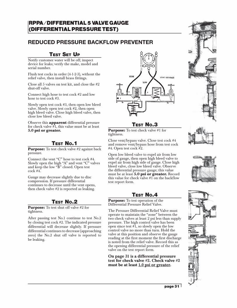
TesT seT UpNotify customer water will be off; inspect device for leaks; verify the make, model and serial number.
Flush test cocks in order (4-1-2-3), without the relief valve, then install brass fittings.
Close all 5 valves on test kit, and close the #2 shut-off valve.
Connect high hose to test cock #2 and low hose to test cock #3.
Slowly open test cock #3, then open low bleed valve. Slowly open test cock #2, then open high bleed valve. Close high bleed valve, then close low bleed valve.
Observe this apparent differential pressure for check valve #1, this value must be at least 5.0 psi or greater.
TesT No.1Purpose: To test check valve #2 against back pressure.
Connect the vent “C” hose to test cock #4. Slowly open the high “A” and vent “C” valves and keep the low “B” closed. Open test cock #4.
Gauge may decrease slightly due to disc compression. If pressure differential continues to decrease until the vent opens, then check valve #2 is reported as leaking.
TesT No.2Purpose: To test shut off valve #2 for tightness.
After passing test No.1 continue to test No.2 by closing test cock #2. The indicated pressure differential will decrease slightly. If pressure differential continues to decrease (approaching zero) the No.2 shut off valve is reported to be leaking.
TesT No.3 Purpose: To test check valve #1 for tightness.
Close vent/bypass valve. Close test cock #4 and remove vent/bypass hose from test cock #4. Open test cock #2.
Open low bleed valve to expel air from low side of gauge, then open high bleed valve to expel air from high side of gauge. Close high bleed valve, close low bleed valve. Observe the differential pressure gauge; this value must be at least 5.0 psi or greater. Record this value for check valve #1 on the backflow test report form.
TesT No.4Purpose: To test operation of the Differential Pressure Relief Valve.
The Pressure Differential Relief Valve must operate to maintain the “zone” between the two check valves at least 2 psi less than supply pressure. The high control valve has been open since test #1, so slowly open the low control valve no more than turn. Hold the valve at this position and observe the gauge reading at the first moment the first discharge is noted from the relief valve. Record this as the opening differential pressure of the relief valve on the test report form.
On page 31 is a differential pressure test for check valve #2. Check valve #2 must be at least 1.0 psi or greater.
page 32
DIFFERENTIAL PRESSURE TEST ON CHECK VALVE #2
(Check valve #2 must be at least 1.0 psi or greater)
Test #5 is a required test. In addition to test #1 which is a back pressure test on check valve #2, you must perform this differential pressure test to confirm the true integrity of check valve #2.
TesT No.5Purpose: To do a differential pressure test instead of a back pressure test on check valve #2.
After completing test No.4 close test cock #2, then close test cock #3. Close all five valves on test kit.
Move low hose to test cock #4, then move high hose to test cock #3.
Slowly open test cock #4, then open the low bleed valve. Slowly open test cock #3, then open the high bleed valve. Close high bleed valve, then close low bleed valve.
Observe the differential pressure gauge; this value must be at least 1.0 psi or greater. Record this value for check valve #2 on the backflow test report form.
End of test. Make sure all test cocks are closed. Remove hoses and fittings. Slowly open shut-off valve #2 to restore water supply to the customer
page 33
DIFFERENTIAL PRESSURE TEST ON CHECK VALVE #2 (WATER SYSTEMS PLEASE USE YOUR OWN LETTERHEAD)
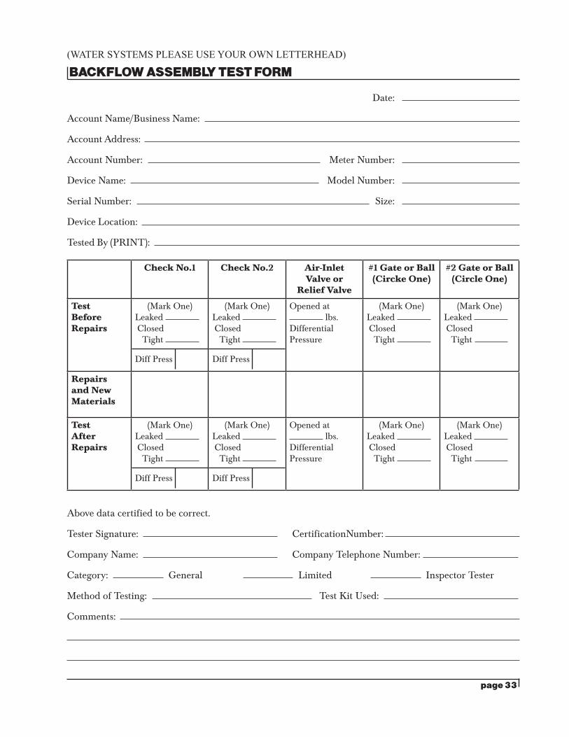
BACKFLOW ASSEMBLY TEST FORM
Date:
Account Name/Business Name:
Account Address:
Account Number: Meter Number:
Device Name: Model Number:
Serial Number: Size:
Device Location:
Tested By (PRINT):
Above data certified to be correct.
Tester Signature: CertificationNumber:
Company Name: Company Telephone Number:
Category: General Limited Inspector Tester
Method of Testing: Test Kit Used:
Comments:
Check No.1 Check No.2 Air-Inlet Valve or
Relief Valve
#1 Gate or Ball (Circke One)
#2 Gate or Ball (Circle One)
Test Before Repairs
(Mark One)Leaked Closed Tight
Diff Press
(Mark One)Leaked Closed Tight
Diff Press
Opened at lbs.
Differential Pressure
(Mark One)Leaked Closed Tight
(Mark One)Leaked Closed Tight
Repairs and New Materials
Test After Repairs
(Mark One)Leaked Closed Tight
Diff Press
(Mark One)Leaked Closed Tight
Diff Press
Opened at lbs.
Differential Pressure
(Mark One)Leaked Closed Tight
(Mark One)Leaked Closed Tight
page 34
WHERE TO SEND DIFFERENTIAL GAUGE FOR CALIBRATION
Gauge calibrations for the differential gauges used in the backflow prevention testing may be calibrated as follows:
The following test kits may be mailed to:
Watts: TK-9, TK-9A, and TK-99E
Orange Research, Inc.Mr. Don Malizia
140 Cascade Blvd.Milford, CN 06460
Phone (203) 877-5657
The gauge itself must be removed from the rest of the test kit and mailed to the above address. Most often the gauge will not be calibrated, but a new one will be returned to you.
The following test kits may be mailed to:
Watts: TKDP, TKDR, TK99D, and all other differential gauges can be sent to:
BavcoMr. John Gould or Mr. Pedro Quraz
20435 South Susana RoadLong Beach, CA 90810Phone (310) 639-5231
The following test kits may be mailed to:
Midwest: Models 830, 844, 845-3, 845-5, 860, 890 Conbraco: Models 40-200 TK, 40-200 TK5
Ames: Model ATG
Midwest Instrument CompanyMrs. Sue Darrow or Mr. Mike Lueck
6500 Dorby DriveSterling Heights, MI 48314
Phone (800) 648-5778 ext 106 or 120
page 35
The following test kits may be mailed to:
Midwest: Models 830, 844, 845-3, 845-5, 860, 890 Conbraco: Models 40-200 TK, 40-200 TK5
Ames: Model ATG
Speciality Valve & Controls CompanyMrs. Mary Anne Kelly3001 Griffith StreetCharlotte, NC 28203
Phone (704) 522-9873
The following test kits may be mailed to:
Promaster: asrP4, asDC4, and all other differential gauges can be sent to:
Astra Industrial Services, Inc.Mrs. Kathy Frahm
3525 Old Conejo Rd.Suite 104
Newbury, CA 91320Phone (800) 776-1464
The following test kits may be mailed to:
Itt Barton: moDel 246, 247, anD 100BFt
Nuflo Measurement SystemsMr. Ben Fuentes
2500 Steven RoadOdessa, Texas 79764Phone (800) 535-8753
In addition to the above locations (which are manufacturers), you may contact any qualified local vender or shop to have your gauge calibrated. You may want to check and compare the price before agreeing to the work.
page 36

page 37
page 38
page 39
page 40
page 41
page 42
page 43
page 44
page 45
page 46
page 47
page 48
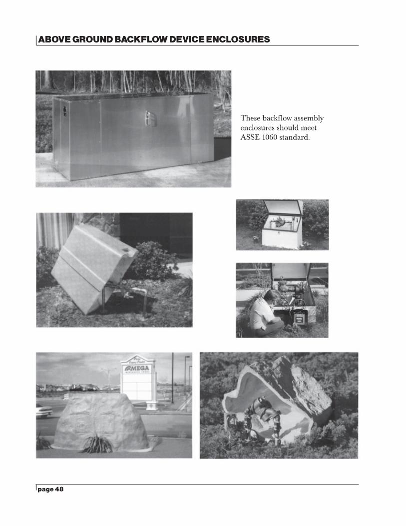
ABOVE GROUND BACKFLOW DEVICE ENCLOSURES
These backflow assembly enclosures should meet ASSE 1060 standard.

page 49CR-000090 1/18