backflow prevention program - gainesville, … · city of gainesville public utilities backflow...
TRANSCRIPT
CITY OF GAINESVILLE PUBLIC UTILITIES
BACKFLOW PREVENTION PROGRAM
SPECIFICATIONS AND DETAILS FOR INSTALLATION OF BACKFLOW ASSEMBLIES
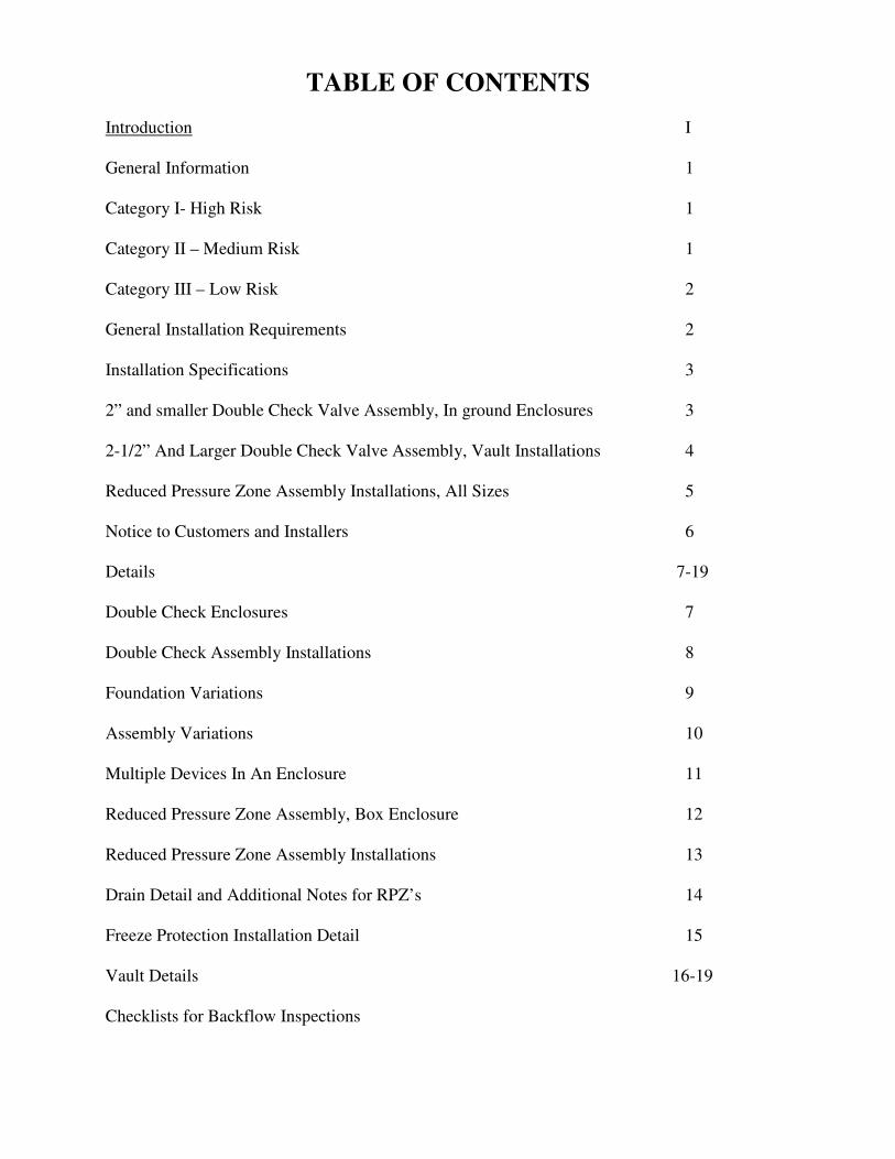
TABLE OF CONTENTS
Introduction I General Information 1 Category I- High Risk 1 Category II – Medium Risk 1 Category III – Low Risk 2 General Installation Requirements 2 Installation Specifications 3 2” and smaller Double Check Valve Assembly, In ground Enclosures 3 2-1/2” And Larger Double Check Valve Assembly, Vault Installations 4 Reduced Pressure Zone Assembly Installations, All Sizes 5 Notice to Customers and Installers 6 Details 7-19 Double Check Enclosures 7 Double Check Assembly Installations 8 Foundation Variations 9 Assembly Variations 10 Multiple Devices In An Enclosure 11 Reduced Pressure Zone Assembly, Box Enclosure 12 Reduced Pressure Zone Assembly Installations 13 Drain Detail and Additional Notes for RPZ’s 14 Freeze Protection Installation Detail 15 Vault Details 16-19 Checklists for Backflow Inspections
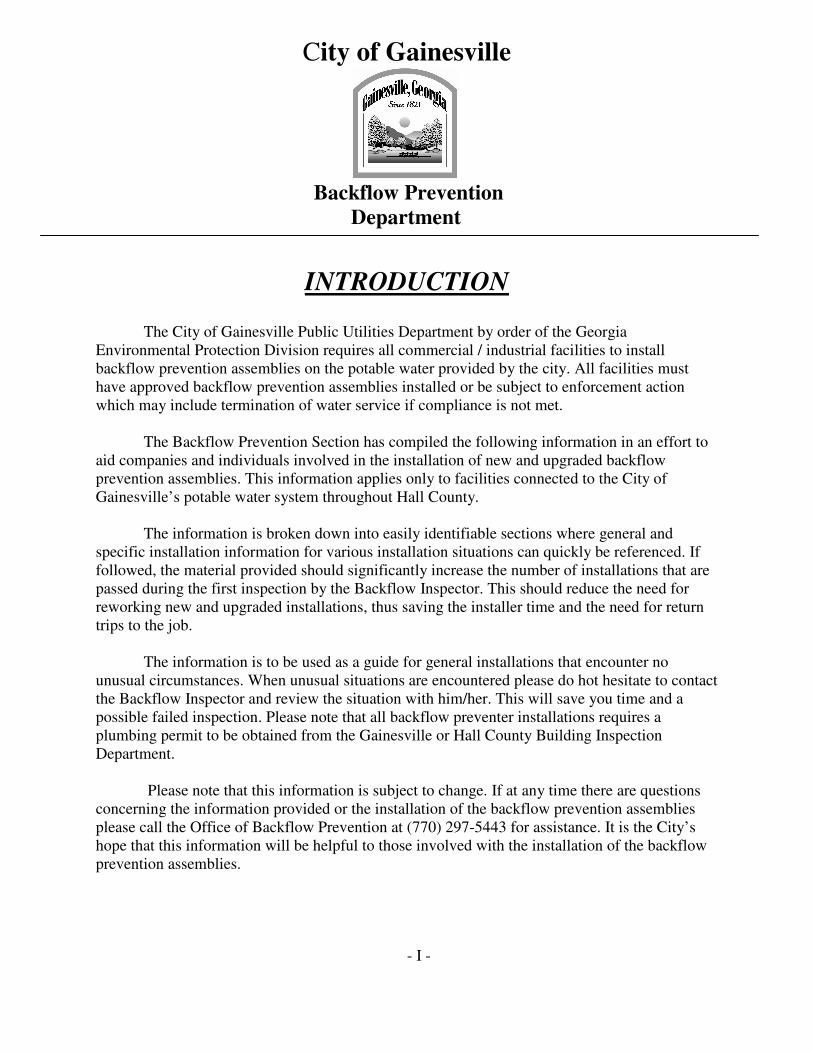
City of Gainesville
Backflow Prevention Department
INTRODUCTION The City of Gainesville Public Utilities Department by order of the Georgia
Environmental Protection Division requires all commercial / industrial facilities to install backflow prevention assemblies on the potable water provided by the city. All facilities must have approved backflow prevention assemblies installed or be subject to enforcement action which may include termination of water service if compliance is not met.
The Backflow Prevention Section has compiled the following information in an effort to aid companies and individuals involved in the installation of new and upgraded backflow prevention assemblies. This information applies only to facilities connected to the City of Gainesville’s potable water system throughout Hall County. The information is broken down into easily identifiable sections where general and specific installation information for various installation situations can quickly be referenced. If followed, the material provided should significantly increase the number of installations that are passed during the first inspection by the Backflow Inspector. This should reduce the need for reworking new and upgraded installations, thus saving the installer time and the need for return trips to the job.
The information is to be used as a guide for general installations that encounter no unusual circumstances. When unusual situations are encountered please do hot hesitate to contact the Backflow Inspector and review the situation with him/her. This will save you time and a possible failed inspection. Please note that all backflow preventer installations requires a plumbing permit to be obtained from the Gainesville or Hall County Building Inspection Department.
Please note that this information is subject to change. If at any time there are questions concerning the information provided or the installation of the backflow prevention assemblies please call the Office of Backflow Prevention at (770) 297-5443 for assistance. It is the City’s hope that this information will be helpful to those involved with the installation of the backflow prevention assemblies.
- I -
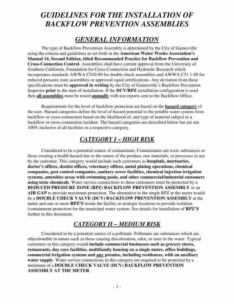
GUIDELINES FOR THE INSTALLATION OF BACKFLOW PREVENTION ASSEMBLIES
GENERAL INFORMATION The type of Backflow Prevention Assembly is determined by the City of Gainesville
using the criteria and guidelines as set forth in the American Water Works Association’s Manual 14, Second Edition, titled Recommended Practice for Backflow Prevention and Cross-Connection Control. Assemblies shall have current approval from the University of Southern California, Foundation for Cross-Connection and Hydraulic Research which incorporates standards AWWA C510-89 for double check assemblies and AWWA C51 1-89 for reduced pressure zone assemblies or approved equal certifications. Any deviation from these specifications must be approved in writing by the City of Gainesville’s Backflow Prevention Inspector prior to the start of installation. If the DCV/RPZ installation configuration is used then all assemblies must be tested annually with test reports sent to the Backflow Office.
Requirements for the level of backflow protection are based on the hazard category of
the user. Hazard categories define the level of hazard potential to the potable water system from backflow or cross-connection based on the likelihood of, and type of material subject to a backflow or cross-connection incident. The hazard categories are described below but are not 100% inclusive of all facilities in a respective category.
CATEGORY I – HIGH RISK
Considered to be a potential source of contaminate. Contaminates are toxic substances or those creating a health hazard due to the nature of the product, raw materials, or processes in use by the customer. This category would include such customers as hospitals, mortuaries, doctor’s offices, dentist offices, veterinary offices, metal plating operations, chemical companies, pest control companies, sanitary sewer facilities, chemical injection irrigation systems, amenities areas with swimming pools, and other commercial/industrial customers using toxic chemicals. Water service connections to these customers must be protected by a REDUCED PRESSURE ZONE (RPZ) BACKFLOW PREVENTION ASSEMBLY or an AIR GAP to provide maximum protection. The alternative to the single RPZ at the meter would be a DOUBLE CHECK VALVE (DCV) BACKFLOW PREVENTION ASSEMBLY at the meter and one or more RPZ’S inside the facility at strategic locations to provide isolation /containment protection for the municipal water system. See details for installation of RPZ’S further in this document.
CATEGORY II – MEDIUM RISK
Considered to be a potential source of a pollutant. Pollutants are substances which are objectionable in nature such as those causing discoloration, odor, or taste in the water. Typical customers in this category would include commercial businesses such as grocery stores, restaurants, day care facilities, multifamily housing on a single meter, office buildings, commercial irrigation systems and any premise, including residences, with an auxiliary water supply. Water service connections in this category are required to be protected by a minimum of a DOUBLE CHECK VALVE (DCV) BACKFLOW PREVENTION ASSEMBLY AT THE METER.
- 1 -
CATEGORY II – LOW RISK
Those considered least likely to be a possible source of a contaminant or pollutant. Typically this category includes single family residential customers. The water service connections to these customers are to be protected by a city provided DUAL CHECK VALVE (DUCV) BACKFLOW PREVENTION ASSEMBLY AT THE METER.
GENERAL INSTALLATION REQUIREMENTS
1) All assemblies are to be installed as close as possible to the water meter. Any variance from this location must be approved prior to installation by the City of Gainesville’s Backflow Inspector. Failure to obtain a variance prior to installation may cause device to be relocated at owner’s expense.
2) Due to the location of the water meter at existing facilities it may not be practical to install a backflow assembly device at the water meter. In these instances the inspector must be contacted to visually inspect and determine the most appropriate location for the backflow device. Once the location is determined a written variance will be prepared for the occupant / owner of the facility. Installation prior to inspection may not be acceptable and the backflow device may be required to be relocated at owner’s expense.
3) Backflow assemblies shall include a full ball valve on the inlet and outlet sides. Devices larger than two inches (2”) may have gate valves. Devices shall be fitted with three (3) ball valve test cocks and a fourth ball valve test cock on the upstream side of the inlet shutoff valve. All Test cocks shall be fitted with brass, stainless or plastic plugs, or plastic caps to keep the test cocks clean and free of debris.
4) No galvanized nipples or fittings can be installed directly into/onto an assembly, unless a dielectric or insulating fitting is used to separate the dissimilar metals
5) All fire systems are required to have DOUBLE DETECTOR CHECK (DDC) BACKFLOW PREVENTION ASSEMBLIES as shown in accompanying details.
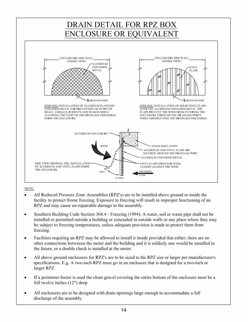
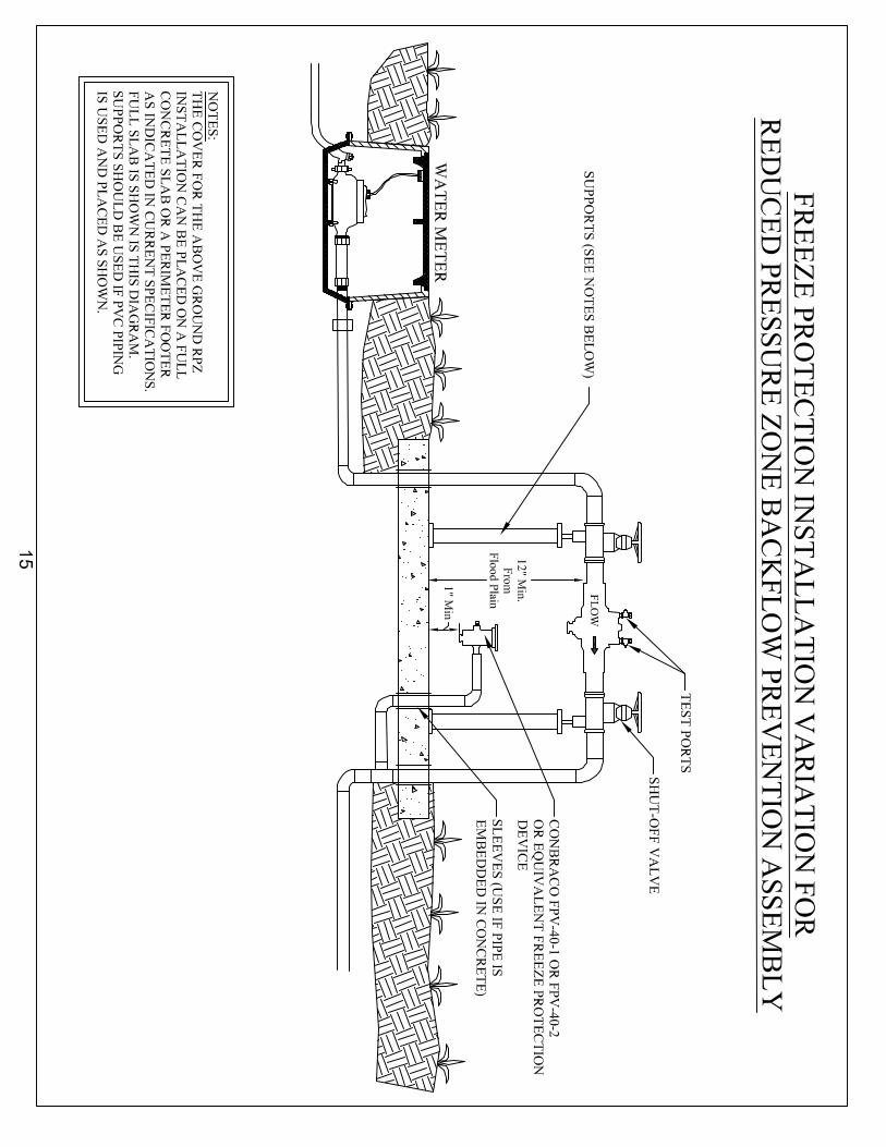
6) Reduced pressure zone (RPZ) devices installed outside must have a minimum of twelve inches (12”) clearance from the bottom of the device to the ground and in a freeze proof box that will allow for drainage when the device discharges. Additional notes on RPZ installations are in the RPZ Installation Details and Specifications section of this document.
7) Any device installed inside, RPZ or double check, must be installed per manufacturers specifications and easily accessible for inspection, testing and repair. 8) A Certified Backflow Assembly tester approved by the City of Gainesville must test all assemblies. A current testers list can be obtained from the Office of Backflow inspection.
9) Initial testing must be done prior to final approval of backflow installation or issuance of a C.O. and test reports forwarded to the Backflow Office. Assemblies are to be tested annually thereafter and reports forwarded to the City within ten (10) working days of the test, Failure to test and forward the report within the allotted time may result in removal of the tester’s name from the approved list for a minimum of three (3) months. Companies and testers who continually fail to supply test reports within the allotted time maybe removed from the approved list for a longer period at the discretion of the City.
- 2 -
INSTALLATION SPECIFICATIONS
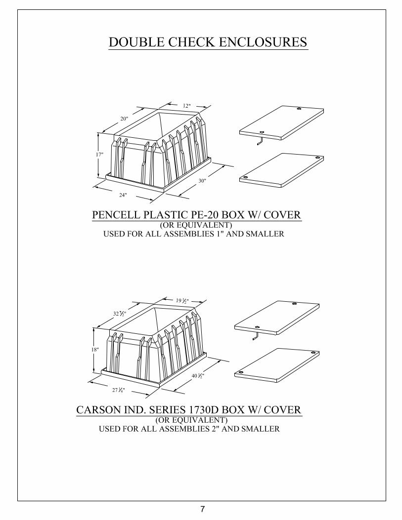
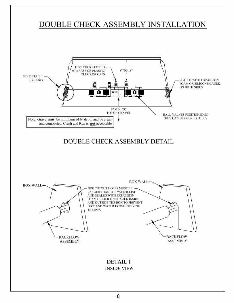
2” AND SMALLER DOUBLE CHECK VALVE (DCV) ASSEMBLY INGROUND ENCLOSURES
1) See the attached box detail sheet for example of the acceptable box to be used in non-traffic areas. This box or one of near equal dimensions may be used. Installations in concrete or asphalt shall have drop-in covers. Installations in grassy areas may have either drop-in covers or covers that overlap the top of the box. If the box is to be set in concrete, asphalt, or an area subject to other than foot traffic, the box and cover must be designed for such an installation.
2) Top of box shall be at grade or above to prevent flooding of installation.
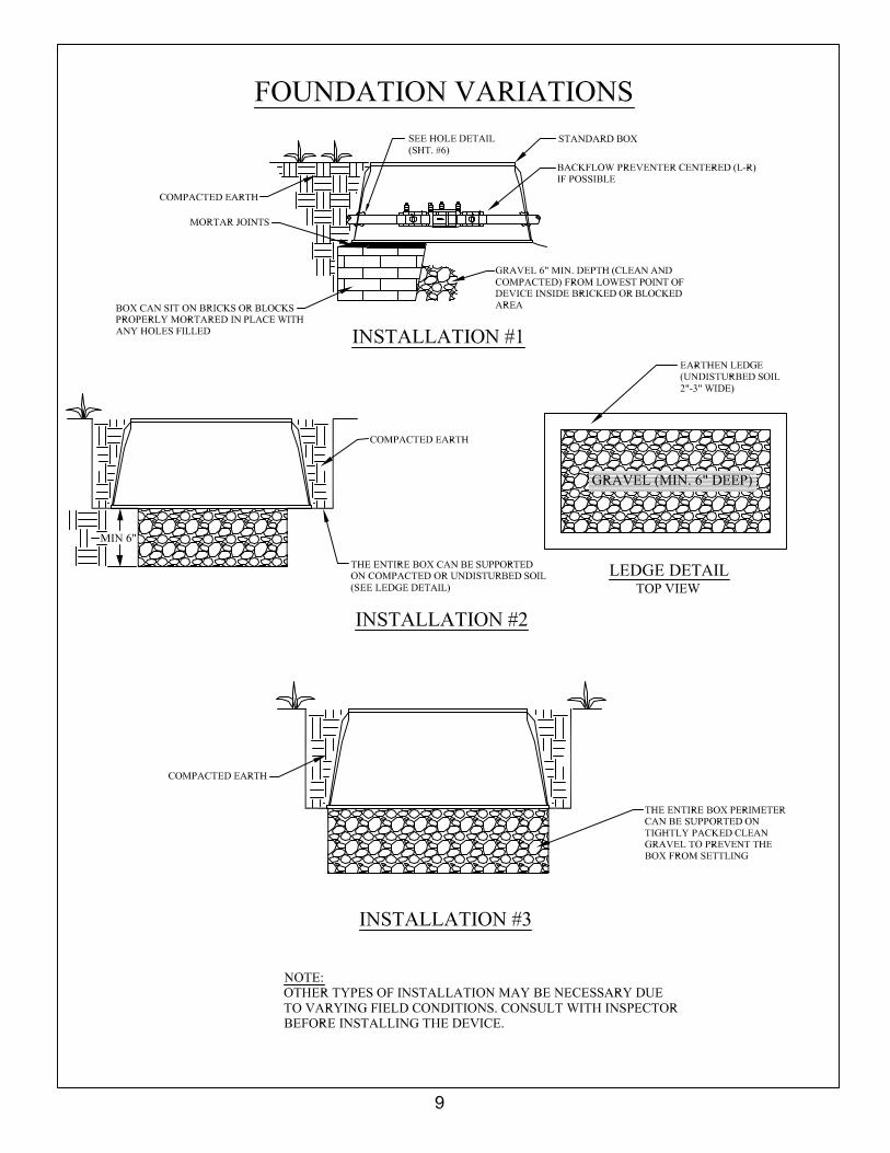
3) The entire box bottom perimeter shall be supported on compacted or undisturbed soil, poured concrete base, complete courses of brick or block properly mortared in place, or tightly packed clean gravel to prevent the box from settling. If the service line is at a depth that warrants an adjustment of the box elevation, then complete courses of bricks or blocks, properly mortared in place, may be used to support the entire box bottom, or a commercial box riser may be used to bring the box top level up to grade or above.
4) The box shall not rest directly on the water line. Pipe cutout holes must be larger than the water line and sealed with expansion foam or silicone caulk to prevent dirt and water from entering the box.
5) The box must have clean, compacted gravel at least six inches (6”) deep covering the entire bottom to allow for good drainage. No mud, dirt, debris, etc. shall be left in the box.
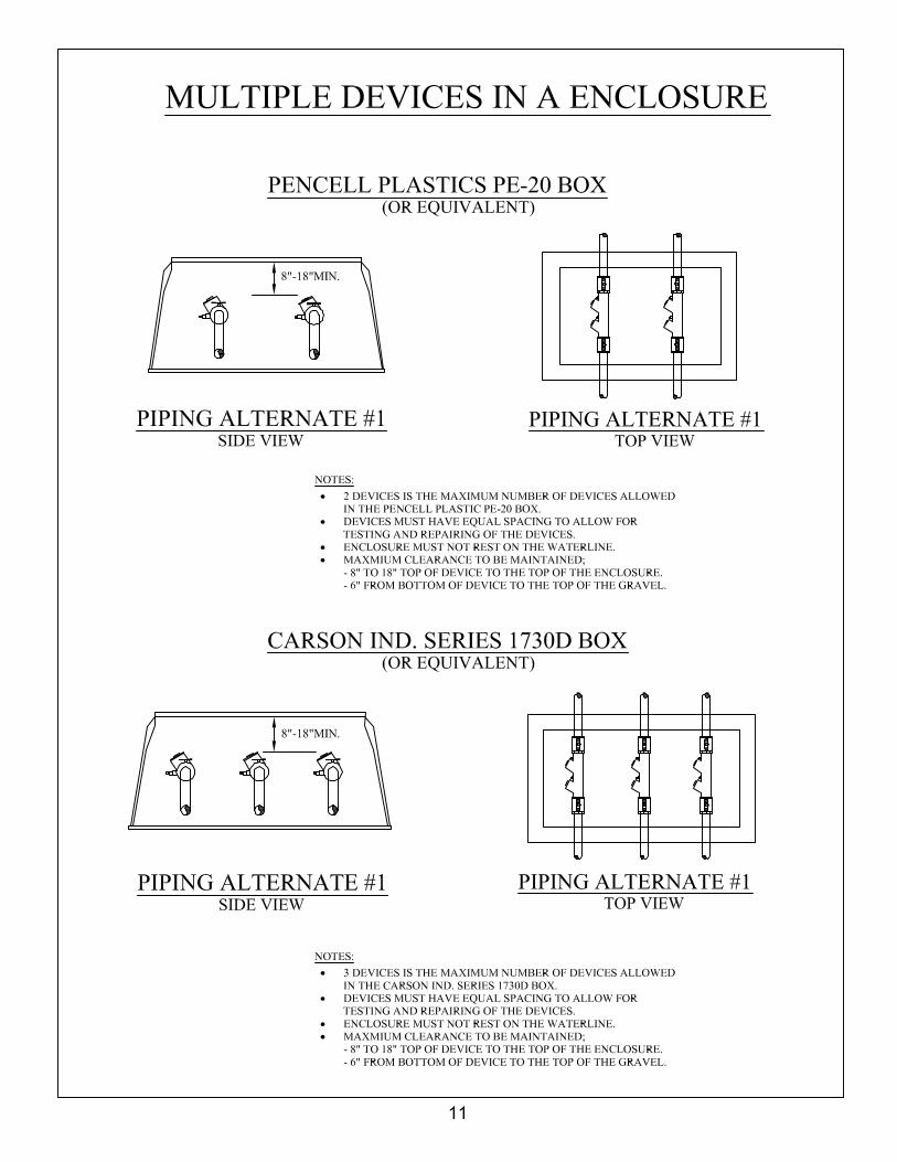
6) The backflow assembly must: � be clean � be centered in the box if installation will permit � be positioned with test cocks in a vertical position if possible � have no galvanized fittings attached directly into/onto device � have test cocks fitted with brass, stainless, or plastic plugs/caps � have the lowest point on assembly a minimum of 6” from the gravel � have top of device between 8” and 18” from the bottom of the cover � have ball valves positioned so they can be opened fully from top or side � be sized to the water meter, i.e. 1” meter will require 1” backflow device � have attached to, or cast in the body, manufactures name, model and serial number � be tested and pass following installation and test report forwarded to Backflow Office
prior to issuance of a C.O.
- 3 -
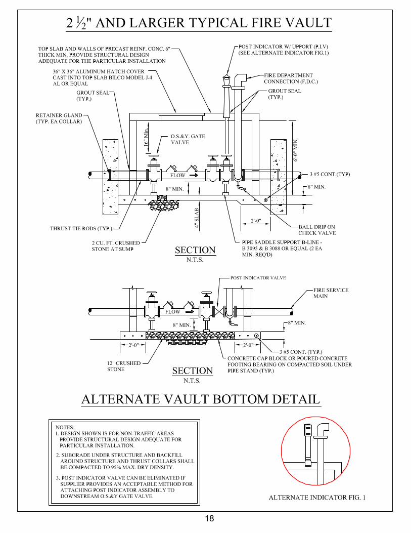
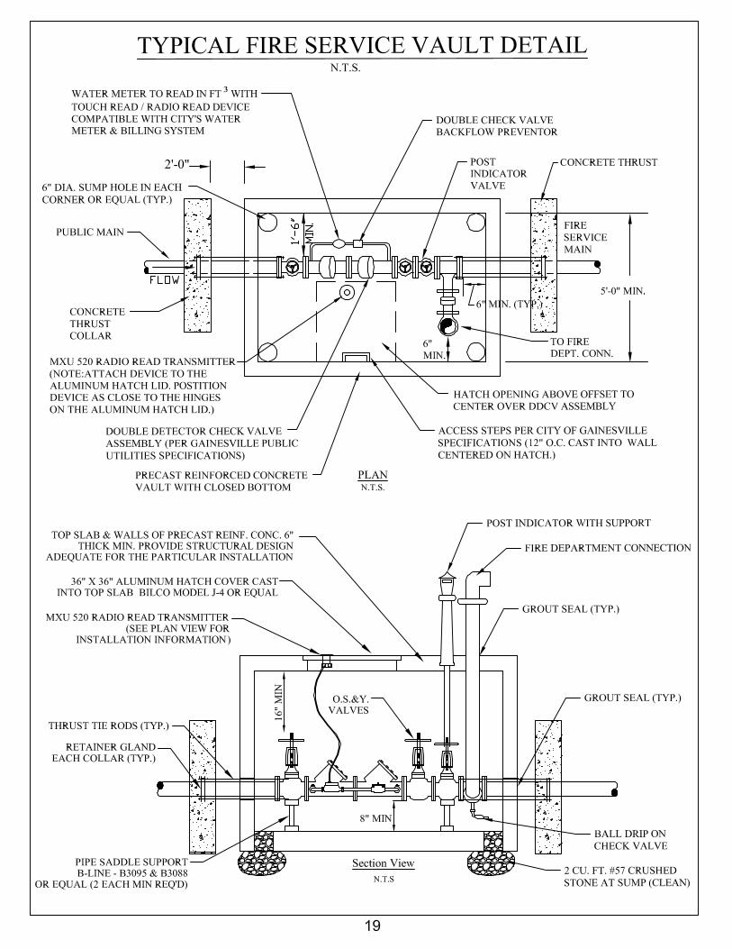
2-1/2” AND LARGER DOUBLE CHECK VALVE (DCV)
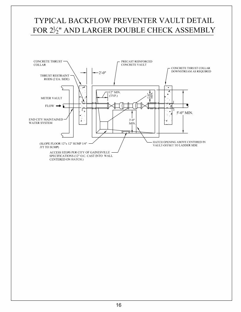
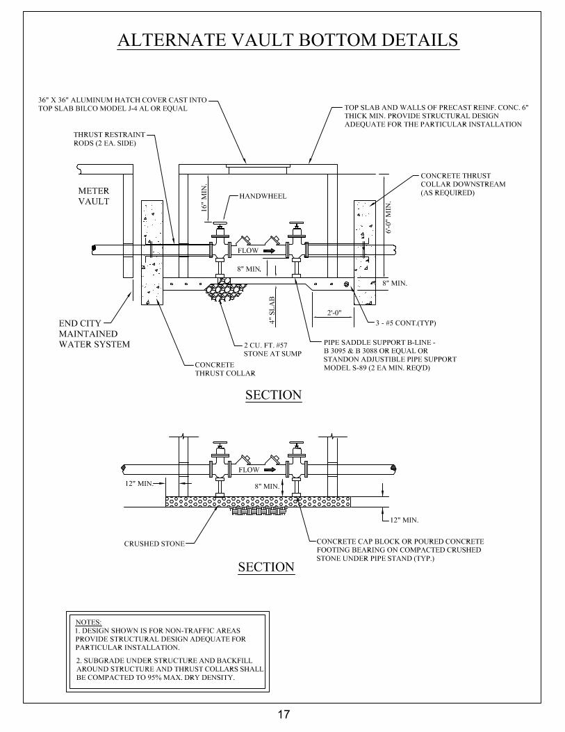
ASSEMBLY IN VAULTS 1) See attached vault detail sheets for proper installation of 2-1/2” and larger assemblies in precast, reinforced concrete vaults. Details cover domestic and fire service applications. A complete package precast vault per details may be used.
2) All assemblies must be supported with commercial pipe supports at locations shown on the attached vault detail sheets. In open bottom vaults the pipe supports must be on concrete cap blocks or poured concrete footing placed on compacted soil or directly, on top of compacted clean gravel concrete blocks, bricks, pieces of wood, etc. are not acceptable as pipe supports and shimming is not allowed.
3) There must be a minimum of eight inches (8”) clearance between the bottom of the device and the gravel or vault bottom.
4) Open bottom vault must have clean, compacted gravel at least twelve inches (12”) deep covering the entire bottom to allow for good drainage, with no trash, mud or other left in the vault.
5) The ends of the vault where the pipe enters and exits must be concreted in or properly blocked in with mortared bricks or blocks.
6) Minimum size 3’ x 3’ aluminum hatch is to be offset to step side of vault and centered over the steps. 7) Steps are to be twelve inches (12”) on centers maximum and centered in the hatch opening.
8) In fire service vaults the detector check must be on the opposite side of the vault from the wall steps.
9) Solid bottom vaults shall be set in such a manner to allow for complete drainage through drainage sump openings that are provided.
10) The backflow assembly must: � be located in vault per details � be fitted with gate valves � be positioned with test cocks in a vertical position if possible � have no galvanized fittings attached directly into/onto device � have test cocks fitted with brass, stainless, or plastic plugs/caps � be sized to the water meter, i.e. 3” meter will require 3” backflow device � have the lowest point on the assembly a minimum of 8” from the gravel or solid bottom � have attached to, or cast in the body, manufactures name, model and serial number � be tested and pass following installation and test report forwarded to Backflow Office
prior to issuance of a C.O.
- 4 -
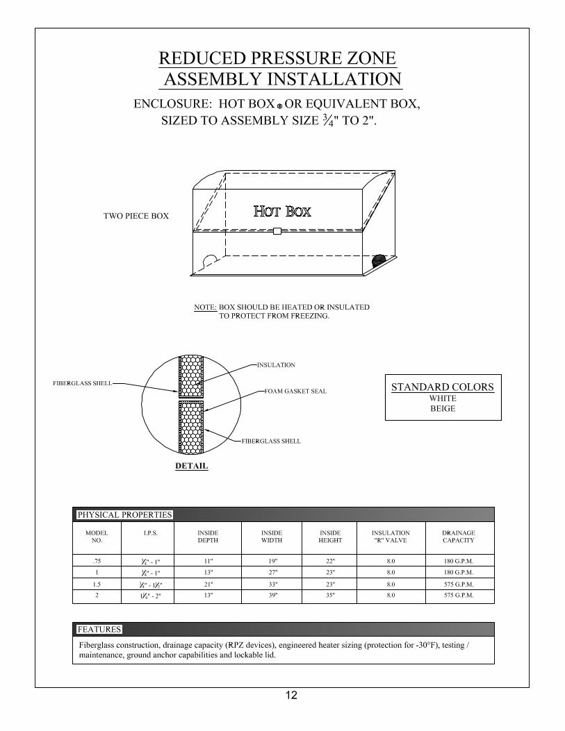
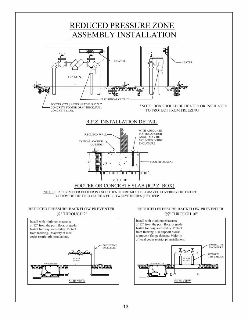
REDUCED PRESSURE ZONE (RPZ) ASSEMBLY
INSTALLATIONS – ALL SIZES 1) All Reduced Pressure Zone Assemblies (RPZ’s) are to be installed above ground or inside the facility to protect from freezing. Exposure to freezing will result in improper functioning of an RPZ and may cause permanent damage to the assembly. 2) Southern Building Code Section 304.4 (1994) - Freezing : A water, soil, or waste pipe shall not be installed or permitted outside of a building or concealed in outside walls or any place where they may be subject to freezing temperatures, unless adequate provision is made to protect them from freezing. 3) Reduced Pressure Zone Assemblies that are installed inside a facility are required to have an air gap and discharge line installed to catch water that the device will periodically discharge. 4) Facilities requiring an RPZ may be allowed to install it inside provided that either:
� there are no other connections between the meter and the building and it is unlikely one would be installed in the future or,
� a double check is installed at the meter. 5) All above ground enclosures for RPZ’s are to be sized to the RPZ size or larger per manufacturer’s specifications. E.g. A two-inch (2”) RPZ must go in an enclosure designed for a two-inch (2”) or larger RPZ. 6) The base on which an above ground enclosure sits may be a complete slab or perimeter footer. If a perimeter footer is used then clean gravel covering the entire bottom of the enclosure must be a full twelve inches (12”) deep. See details on page 13. 7) All enclosures are to be designed with drain openings large enough to accommodate a full discharge of the assembly. 8) The reduced pressure zone assembly must:
� be centered in the box if installation will permit � be positioned with test cocks in a vertical position if possible � have no galvanized fittings attached directly into/onto device � have test cocks fitted with brass, stainless, or plastic plugs/caps � have ball valves positioned so they can be opened fully from top or side � be sized to the water meter, i.e. 1” meter will require 1” backflow device � have the lowest point on the assembly a minimum of 12” from the gravel or solid bottom � have attached to, or cast in the body, manufactures name, model and serial number � be tested and pass following installation and test report forwarded to Backflow Office
prior to issuance of a C.O.
- 5 -
NOTICE TO CUSTOMERS AND INSTALLERS 1) Ownership of the backflow assembly and responsibility for its testing, maintenance, and proper operation are that of the property owner.
2) The City of Gainesville neither accepts responsibility nor liability for the backflow assembly being tested, maintained, or operating properly.
3) Backflow assemblies are to be installed by a licensed plumber and repairs made by a licensed Master Plumber.
4) Installation of a Backflow Prevention Assembly on a service line creates a closed system. Provisions should be made for thermal expansion in the customer’s system.
If you need more information, please contact the City of Gainesville’s Backflow Prevention Office at (770) 297-5443 or fax (770)538-2411.
Revised: January 3, 2007
- 6 -
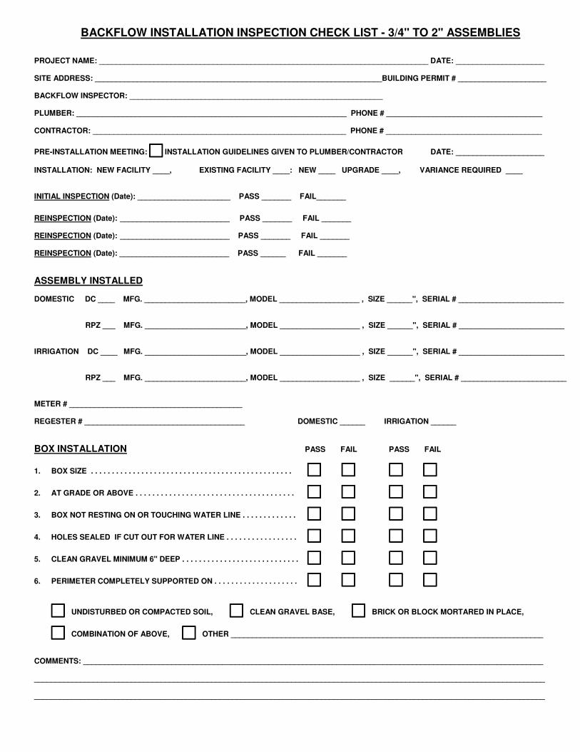
BACKFLOW INSTALLATION INSPECTION CHECK LIST - 3/4" TO 2" ASSEMBLIES
PROJECT NAME: ______________________________________________________________________________ DATE: _____________________ SITE ADDRESS: ____________________________________________________________________BUILDING PERMIT # _____________________ BACKFLOW INSPECTOR: ____________________________________________________________ PLUMBER: ________________________________________________________________ PHONE # _____________________________________ CONTRACTOR: ____________________________________________________________ PHONE # _____________________________________
PRE-INSTALLATION MEETING: ���� INSTALLATION GUIDELINES GIVEN TO PLUMBER/CONTRACTOR DATE: _____________________ INSTALLATION: NEW FACILITY ____, EXISTING FACILITY ____: NEW ____ UPGRADE ____, VARIANCE REQUIRED ____ INITIAL INSPECTION (Date): ______________________ PASS _______ FAIL_______ REINSPECTION (Date): __________________________ PASS _______ FAIL _______ REINSPECTION (Date): __________________________ PASS _______ FAIL _______ REINSPECTION (Date): __________________________ PASS ______ FAIL _______ ASSEMBLY INSTALLED DOMESTIC DC ____ MFG. ________________________, MODEL ___________________ , SIZE ______", SERIAL # _________________________
RPZ ___ MFG. ________________________, MODEL ___________________ , SIZE ______", SERIAL # _________________________
IRRIGATION DC ____ MFG. ________________________, MODEL ___________________ , SIZE ______", SERIAL # _________________________
RPZ ___ MFG. ________________________, MODEL ___________________ , SIZE ______", SERIAL # _________________________
METER # _________________________________________
REGESTER # ______________________________________ DOMESTIC ______ IRRIGATION ______ BOX INSTALLATION PASS FAIL PASS FAIL
1. BOX SIZE . . . . . . . . . . . . . . . . . . . . . . . . . . . . . . . . . . . . . . . . . . . . . . . . �������� �������� ��������������������������������
2. AT GRADE OR ABOVE . . . . . . . . . . . . . . . . . . . . . . . . . . . . . . . . . . . . . . �������� �������� ������������������������������������
3. BOX NOT RESTING ON OR TOUCHING WATER LINE . . . . . . . . . . . . . �������� �������� ������������������������������������
4. HOLES SEALED IF CUT OUT FOR WATER LINE . . . . . . . . . . . . . . . . . �������� �������� ������������������������������������
5. CLEAN GRAVEL MINIMUM 6" DEEP . . . . . . . . . . . . . . . . . . . . . . . . . . . . �������� �������� ��������������������������������
6. PERIMETER COMPLETELY SUPPORTED ON . . . . . . . . . . . . . . . . . . . . �������� �������� ����������������������������
��������UNDISTURBED OR COMPACTED SOIL, ��������CLEAN GRAVEL BASE, ��������BRICK OR BLOCK MORTARED IN PLACE,
��������COMBINATION OF ABOVE, ��������OTHER __________________________________________________________________________
COMMENTS: _____________________________________________________________________________________________________________ _________________________________________________________________________________________________________________________ _________________________________________________________________________________________________________________________
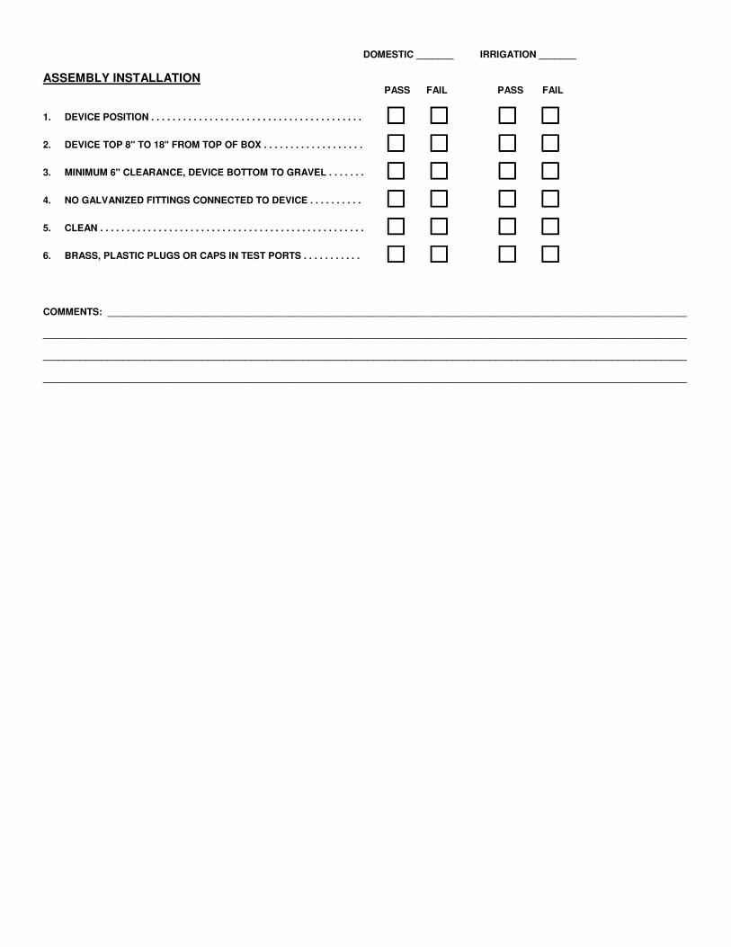
DOMESTIC _______ IRRIGATION _______
ASSEMBLY INSTALLATION
PASS FAIL PASS FAIL
1. DEVICE POSITION . . . . . . . . . . . . . . . . . . . . . . . . . . . . . . . . . . . . . . . . �������� �������� ������������������������������������
2. DEVICE TOP 8" TO 18" FROM TOP OF BOX . . . . . . . . . . . . . . . . . . . �������� �������� ������������������������������������
3. MINIMUM 6" CLEARANCE, DEVICE BOTTOM TO GRAVEL . . . . . . . �������� �������� ������������������������������������
4. NO GALVANIZED FITTINGS CONNECTED TO DEVICE . . . . . . . . . . �������� �������� ������������������������������������
5. CLEAN . . . . . . . . . . . . . . . . . . . . . . . . . . . . . . . . . . . . . . . . . . . . . . . . . . �������� �������� ������������������������������������
6. BRASS, PLASTIC PLUGS OR CAPS IN TEST PORTS . . . . . . . . . . . �������� �������� ������������������������������������
COMMENTS: _____________________________________________________________________________________________________________ _________________________________________________________________________________________________________________________ _________________________________________________________________________________________________________________________ _________________________________________________________________________________________________________________________
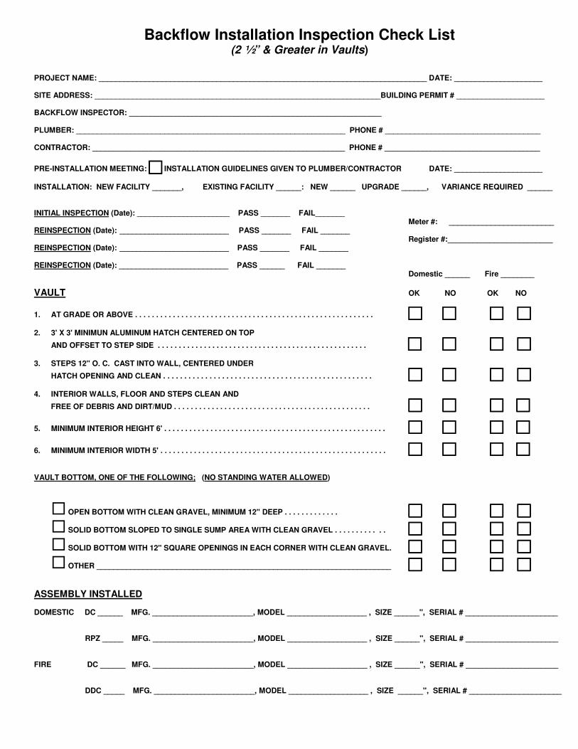
Backflow Installation Inspection Check List
(2 ½” & Greater in Vaults)
PROJECT NAME: ______________________________________________________________________________ DATE: _____________________ SITE ADDRESS: ____________________________________________________________________BUILDING PERMIT # _____________________ BACKFLOW INSPECTOR: ____________________________________________________________ PLUMBER: ________________________________________________________________ PHONE # _____________________________________ CONTRACTOR: ____________________________________________________________ PHONE # _____________________________________
PRE-INSTALLATION MEETING: ���� INSTALLATION GUIDELINES GIVEN TO PLUMBER/CONTRACTOR DATE: _____________________ INSTALLATION: NEW FACILITY _______, EXISTING FACILITY ______: NEW ______ UPGRADE ______, VARIANCE REQUIRED ______ INITIAL INSPECTION (Date): ______________________ PASS _______ FAIL_______ Meter #: _________________________ REINSPECTION (Date): __________________________ PASS _______ FAIL _______ Register #:_________________________ REINSPECTION (Date): __________________________ PASS _______ FAIL _______ REINSPECTION (Date): __________________________ PASS ______ FAIL _______ Domestic ______ Fire ________ VAULT OK NO OK NO
1. AT GRADE OR ABOVE . . . . . . . . . . . . . . . . . . . . . . . . . . . . . . . . . . . . . . . . . . . . . . . . . . . . . . . . . �������� �������� ������������������������ 2. 3' X 3' MINIMUN ALUMINUM HATCH CENTERED ON TOP
AND OFFSET TO STEP SIDE . . . . . . . . . . . . . . . . . . . . . . . . . . . . . . . . . . . . . . . . . . . . . . . . . . �������� �������� ����������������������������
3. STEPS 12" O. C. CAST INTO WALL, CENTERED UNDER
HATCH OPENING AND CLEAN . . . . . . . . . . . . . . . . . . . . . . . . . . . . . . . . . . . . . . . . . . . . . . . . . . �������� �������� ������������������������
4. INTERIOR WALLS, FLOOR AND STEPS CLEAN AND
FREE OF DEBRIS AND DIRT/MUD . . . . . . . . . . . . . . . . . . . . . . . . . . . . . . . . . . . . . . . . . . . . . . . �������� �������� ������������������������
5. MINIMUM INTERIOR HEIGHT 6' . . . . . . . . . . . . . . . . . . . . . . . . . . . . . . . . . . . . . . . . . . . . . . . . . . . . . �������� �������� ������������������������
6. MINIMUM INTERIOR WIDTH 5' . . . . . . . . . . . . . . . . . . . . . . . . . . . . . . . . . . . . . . . . . . . . . . . . . . . . . . �������� �������� ������������������������ VAULT BOTTOM, ONE OF THE FOLLOWING; (NO STANDING WATER ALLOWED)
� OPEN BOTTOM WITH CLEAN GRAVEL, MINIMUM 12" DEEP . . . . . . . . . . . . . �������� �������� ������������������������
� SOLID BOTTOM SLOPED TO SINGLE SUMP AREA WITH CLEAN GRAVEL . . . . . . . . . . . . �������� �������� ������������������������
� SOLID BOTTOM WITH 12" SQUARE OPENINGS IN EACH CORNER WITH CLEAN GRAVEL. �������� �������� ������������������������
� OTHER ______________________________________________________________________ �������� �������� ������������������������ ASSEMBLY INSTALLED DOMESTIC DC ______ MFG. ________________________, MODEL ___________________ , SIZE ______", SERIAL # ______________________
RPZ _____ MFG. ________________________, MODEL ___________________ , SIZE ______", SERIAL # ______________________
FIRE DC ______ MFG. ________________________, MODEL ___________________ , SIZE ______", SERIAL # ______________________
DDC _____ MFG. ________________________, MODEL ___________________ , SIZE ______", SERIAL # ______________________
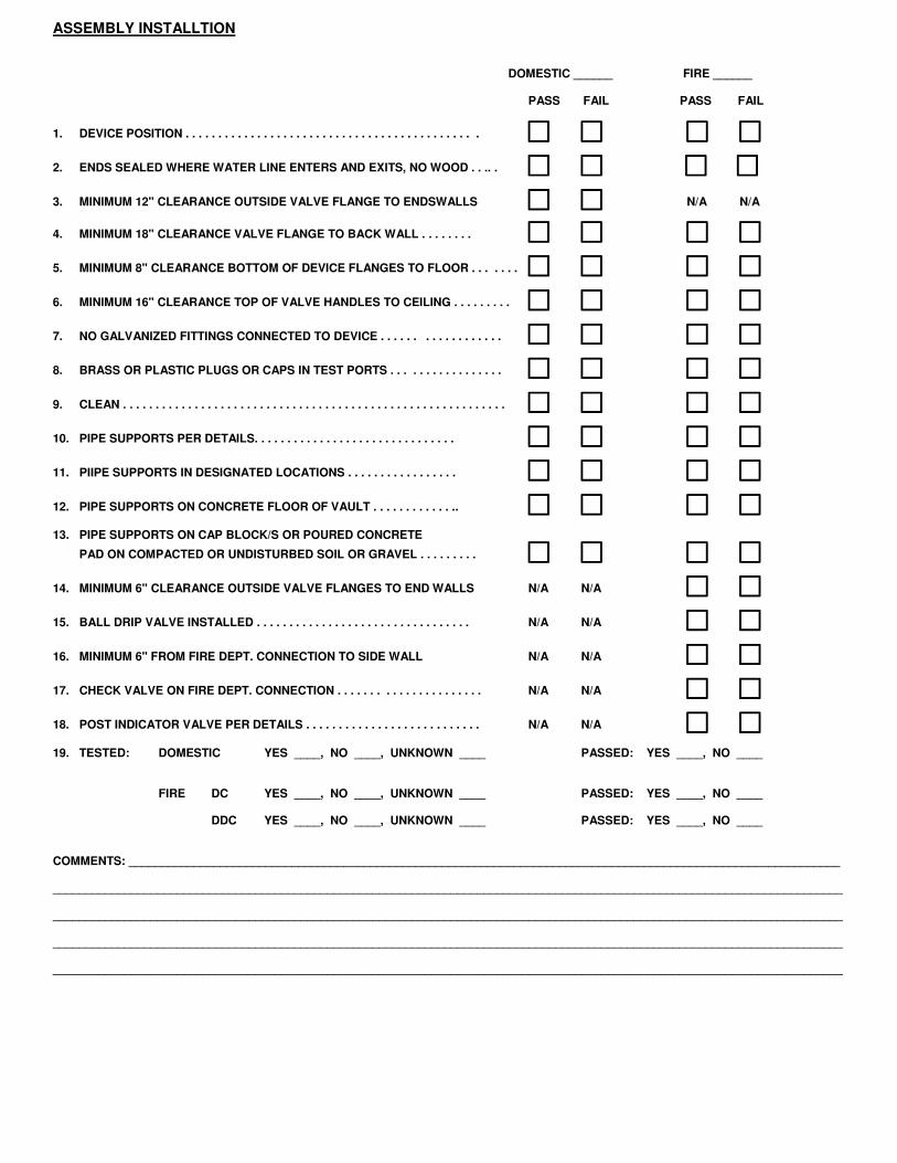
ASSEMBLY INSTALLTION
DOMESTIC ______ FIRE ______
PASS FAIL PASS FAIL
1. DEVICE POSITION . . . . . . . . . . . . . . . . . . . . . . . . . . . . . . . . . . . . . . . . . . . . . �������� �������� ���� �������� ����
2. ENDS SEALED WHERE WATER LINE ENTERS AND EXITS, NO WOOD . . .. . �������� �������� ����������������������������������������
3. MINIMUM 12" CLEARANCE OUTSIDE VALVE FLANGE TO ENDSWALLS �������� �������� ���� N/A���� N/A��������
4. MINIMUM 18" CLEARANCE VALVE FLANGE TO BACK WALL . . . . . . . . �������� �������� ���� �������� ��������
5. MINIMUM 8" CLEARANCE BOTTOM OF DEVICE FLANGES TO FLOOR . . . . . . . �������� �������� ���� �������� ����
6. MINIMUM 16" CLEARANCE TOP OF VALVE HANDLES TO CEILING . . . . . . . . . �������� �������� ���� �������� ����
7. NO GALVANIZED FITTINGS CONNECTED TO DEVICE . . . . . . . . . . . . . . . . . . �������� �������� ���� �������� ����
8. BRASS OR PLASTIC PLUGS OR CAPS IN TEST PORTS . . . . . . . . . . . . . . . . . �������� �������� ���� �������� ����
9. CLEAN . . . . . . . . . . . . . . . . . . . . . . . . . . . . . . . . . . . . . . . . . . . . . . . . . . . . . . . . . . . �������� �������� ���� �������� ����
10. PIPE SUPPORTS PER DETAILS. . . . . . . . . . . . . . . . . . . . . . . . . . . . . . . �������� �������� ���� �������� ����
11. PIIPE SUPPORTS IN DESIGNATED LOCATIONS . . . . . . . . . . . . . . . . . �������� �������� ���� �������� ����
12. PIPE SUPPORTS ON CONCRETE FLOOR OF VAULT . . . . . . . . . . . . .. �������� �������� ���� �������� ���� 13. PIPE SUPPORTS ON CAP BLOCK/S OR POURED CONCRETE
PAD ON COMPACTED OR UNDISTURBED SOIL OR GRAVEL . . . . . . . . . �������� �������� ���� �������� ��������
14. MINIMUM 6" CLEARANCE OUTSIDE VALVE FLANGES TO END WALLS N/A N/A �������� ����
15. BALL DRIP VALVE INSTALLED . . . . . . . . . . . . . . . . . . . . . . . . . . . . . . . . . N/A N/A �������� ����
16. MINIMUM 6" FROM FIRE DEPT. CONNECTION TO SIDE WALL N/A N/A �������� ����
17. CHECK VALVE ON FIRE DEPT. CONNECTION . . . . . . . . . . . . . . . . . . . . . . N/A N/A �������� ����
18. POST INDICATOR VALVE PER DETAILS . . . . . . . . . . . . . . . . . . . . . . . . . . . N/A N/A �������� ���� 19. TESTED: DOMESTIC YES ____, NO ____, UNKNOWN ____ PASSED: YES ____, NO ____
FIRE DC YES ____, NO ____, UNKNOWN ____ PASSED: YES ____, NO ____
DDC YES ____, NO ____, UNKNOWN ____ PASSED: YES ____, NO ____
COMMENTS: _____________________________________________________________________________________________________________ _________________________________________________________________________________________________________________________ _________________________________________________________________________________________________________________________ _________________________________________________________________________________________________________________________ _________________________________________________________________________________________________________________________