background to reinforced concrete design rc buildings
DESCRIPTION
Background to reinforced concrete design, RC buildings,materials, how concrete structures behave and innovations in concrete.TRANSCRIPT
Civil Engineering, Faculty of Engineering & Physical Science, University of Surrey
PG Cert/PG Diploma/MSc in Civil, Bridge & Structural Engineering Page ENGM041.1.1
Unit 1. Background to reinforced concrete design, RC buildings,
materials, how concrete structures behave and innovations in concrete.
(Study time allocation – 20 hours)
Introduction
The purpose of this package is explain the principles and aims of the design of reinforced
concrete structures and to give some background to the design of these buildings.
Although much of the theory used in RC design is fundamental, adhering to the laws of
mechanics, ultimately the design must conform to the requirements of a code of practice.
In this course it is to BS EN 1992-1-1 Eurocode 2: Design of Concrete Structures
published by the British Standards Institution, and which is henceforth referred to as
EC2, Eurocode 2 or simply the Code. Eurocode 2 is a Europe wide code which enables
designers across Europe to practice in any country which adopts the code. There is
however, one proviso, the design of buildings in a specific country requires the National Annex for that country to be applied in the design. The National Annex for the UK for
example contains all the nationally determined parameters which refer specifically to the
UK due to our unique circumstances.
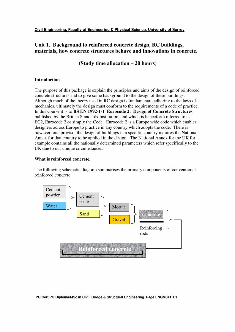
What is reinforced concrete.
The following schematic diagram summarises the primary components of conventional
reinforced concrete.
Cement
powder
Water
Cement
paste
Sand
Mortar
Gravel Concrete
Reinforcing
rods
Reinforced concrete

Civil Engineering, Faculty of Engineering & Physical Science, University of Surrey
PG Cert/PG Diploma/MSc in Civil, Bridge & Structural Engineering Page ENGM041.1.2
Examples of reinforced concrete structures.
High rise reinforced concrete frame
Arch bridge in reinforced concrete

Civil Engineering, Faculty of Engineering & Physical Science, University of Surrey
PG Cert/PG Diploma/MSc in Civil, Bridge & Structural Engineering Page ENGM041.1.3
Simple domestic dwelling. Pre-cast concrete beam.
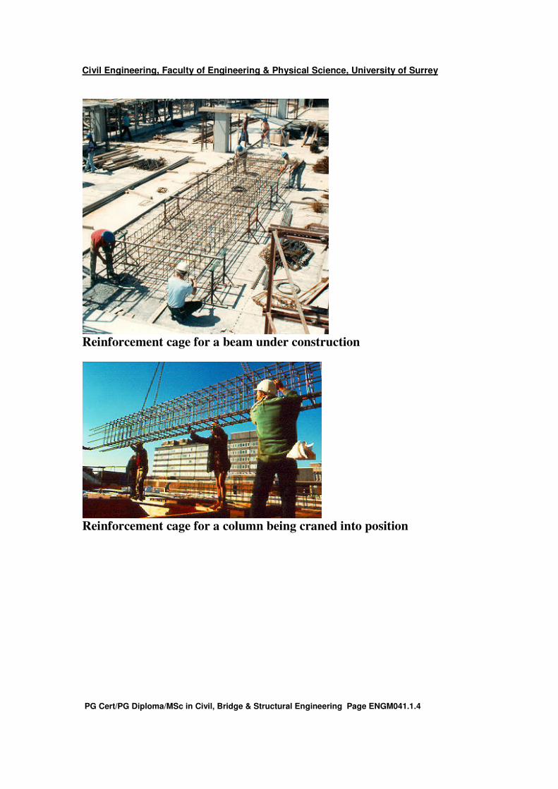
The construction of reinforced concrete structures.
Reinforced concrete comprises concrete and reinforcing bars acting as a composite
material.
Reinforcing cages. Reinforcement in beams and columns consists essentially of straight
longitudinal bars enclosed by links or stirrups which together form a cage of
reinforcement.
Longitudinal bars
Links
Reinforcement cage (Section)
Reinforced
concrete beam
Civil Engineering, Faculty of Engineering & Physical Science, University of Surrey
PG Cert/PG Diploma/MSc in Civil, Bridge & Structural Engineering Page ENGM041.1.4
Reinforcement cage for a beam under construction
Reinforcement cage for a column being craned into position
Civil Engineering, Faculty of Engineering & Physical Science, University of Surrey
PG Cert/PG Diploma/MSc in Civil, Bridge & Structural Engineering Page ENGM041.1.5
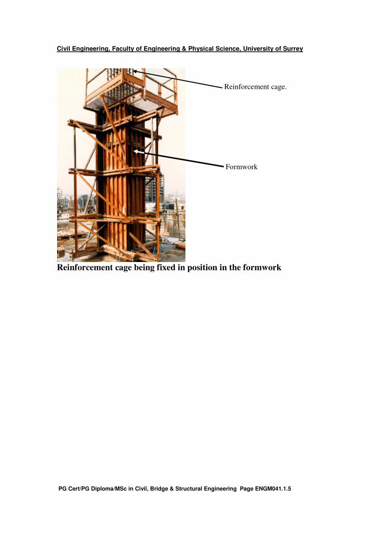
Reinforcement cage being fixed in position in the formwork
Reinforcement cage.
Formwork
Civil Engineering, Faculty of Engineering & Physical Science, University of Surrey
PG Cert/PG Diploma/MSc in Civil, Bridge & Structural Engineering Page ENGM041.1.6
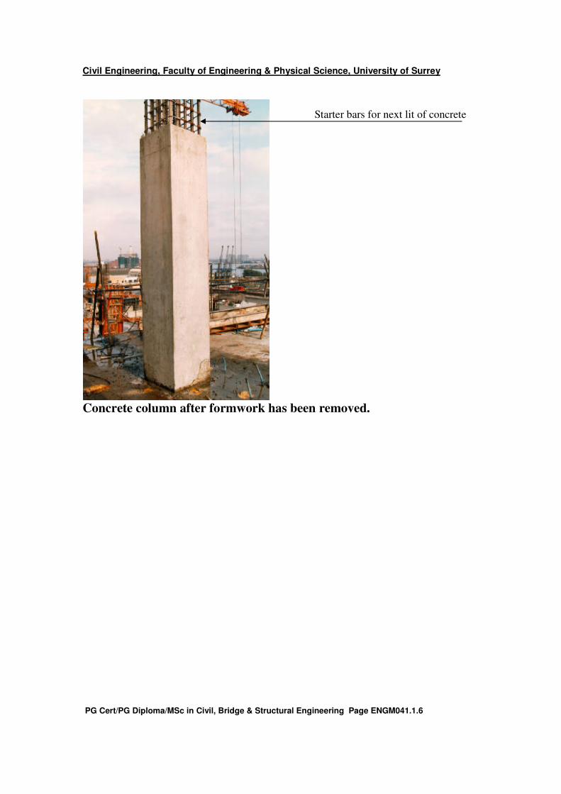
Concrete column after formwork has been removed.
Starter bars for next lit of concrete

Civil Engineering, Faculty of Engineering & Physical Science, University of Surrey
PG Cert/PG Diploma/MSc in Civil, Bridge & Structural Engineering Page ENGM041.1.7
The same building in a more advanced state
Typical two-way spanning floor slab reinforcement.
Formwork for casting slab
supported on the floor below
Column reinforcement cage attached
to starter bars ready for next lift.
Civil Engineering, Faculty of Engineering & Physical Science, University of Surrey
PG Cert/PG Diploma/MSc in Civil, Bridge & Structural Engineering Page ENGM041.1.8
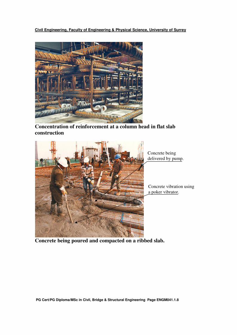
Concentration of reinforcement at a column head in flat slab
construction
Concrete being poured and compacted on a ribbed slab.
Concrete being
delivered by pump.
Concrete vibration using
a poker vibrator.
Civil Engineering, Faculty of Engineering & Physical Science, University of Surrey
PG Cert/PG Diploma/MSc in Civil, Bridge & Structural Engineering Page ENGM041.1.9
Changes to RC design Philosophy.
The philosophy behind design has altered since reinforced concrete was first used as a
structural material. Initially the design was for strength. Structures were made strong
enough to sustain the loads they were to be subject to. The effects of serviceability then
needed to be considered. For example, structures were designed to have limited
deflections so users felt comfortable when using them. Aspects such as fire loading or
the effect of blasts on reinforced concrete had an influence on strength requiring
designers to also consider these. At present designers are being asked to consider all
these aspects as well as to consider the whole life of the structure. In effect designers
need to design economically, ensure the users are happy when occupying the building,
ensure unforeseen circumstances are catered for and then to design for the disposal of the
building in an economic manner when its design life is over. Further, they are required to
design such that the embodied energy is minimised with respect to the whole life running
costs of the building.
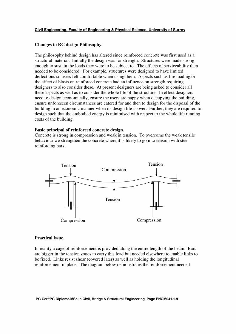
Basic principal of reinforced concrete design. Concrete is strong in compression and weak in tension. To overcome the weak tensile
behaviour we strengthen the concrete where it is likely to go into tension with steel
reinforcing bars.
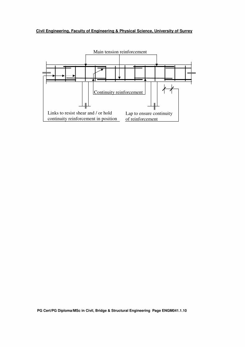
Practical issue.
In reality a cage of reinforcement is provided along the entire length of the beam. Bars
are bigger in the tension zones to carry this load but needed elsewhere to enable links to
be fixed. Links resist shear (covered later) as well as holding the longitudinal
reinforcement in place. The diagram below demonstrates the reinforcement needed
Tension Tension
Tension
Compression Compression
Compression
Civil Engineering, Faculty of Engineering & Physical Science, University of Surrey
PG Cert/PG Diploma/MSc in Civil, Bridge & Structural Engineering Page ENGM041.1.10
Lap to ensure continuity
of reinforcement
Main tension reinforcement
Continuity reinforcement
Links to resist shear and / or hold
continuity reinforcement in position
Civil Engineering, Faculty of Engineering & Physical Science, University of Surrey
PG Cert/PG Diploma/MSc in Civil, Bridge & Structural Engineering Page ENGM041.1.11
Reinforcement – good practice.
1. Well designed reinforcement allows concrete to be placed easily
2. Well designed reinforcement should be easy to fix.
3. Reinforcement helps the concrete to resists externally applied loads. It should
have adequate cover to ensure it is protected, it acts compositely with the concrete
to achieve the required strength and to afford adequate fire protection.
4. Well designed and manufactured reinforcement will form a strong rigid cage
which can be easily placed.
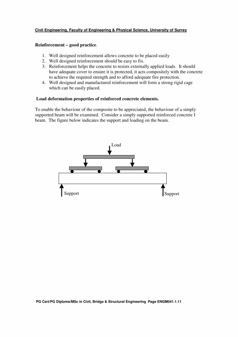
Load deformation properties of reinforced concrete elements.
To enable the behaviour of the composite to be appreciated, the behaviour of a simply
supported beam will be examined. Consider a simply supported reinforced concrete I
beam. The figure below indicates the support and loading on the beam.
Support Support
Load
Civil Engineering, Faculty of Engineering & Physical Science, University of Surrey
PG Cert/PG Diploma/MSc in Civil, Bridge & Structural Engineering Page ENGM041.1.12
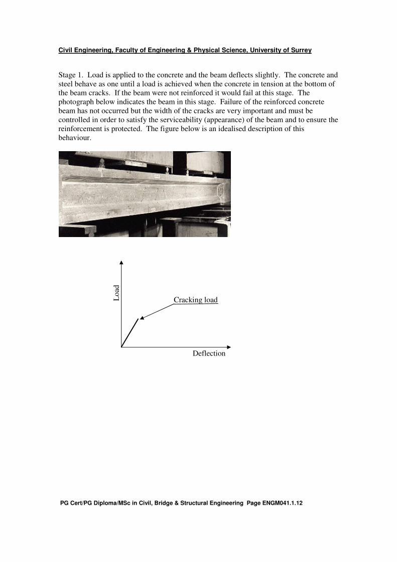
Stage 1. Load is applied to the concrete and the beam deflects slightly. The concrete and
steel behave as one until a load is achieved when the concrete in tension at the bottom of
the beam cracks. If the beam were not reinforced it would fail at this stage. The
photograph below indicates the beam in this stage. Failure of the reinforced concrete
beam has not occurred but the width of the cracks are very important and must be
controlled in order to satisfy the serviceability (appearance) of the beam and to ensure the
reinforcement is protected. The figure below is an idealised description of this
behaviour.
Deflection
Lo
ad
Cracking load
Civil Engineering, Faculty of Engineering & Physical Science, University of Surrey
PG Cert/PG Diploma/MSc in Civil, Bridge & Structural Engineering Page ENGM041.1.13
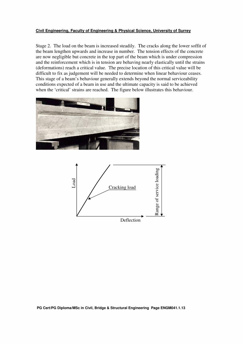
Stage 2. The load on the beam is increased steadily. The cracks along the lower soffit of
the beam lengthen upwards and increase in number. The tension effects of the concrete
are now negligible but concrete in the top part of the beam which is under compression
and the reinforcement which is in tension are behaving nearly elastically until the strains
(deformations) reach a critical value. The precise location of this critical value will be
difficult to fix as judgement will be needed to determine when linear behaviour ceases.
This stage of a beam’s behaviour generally extends beyond the normal serviceability
conditions expected of a beam in use and the ultimate capacity is said to be achieved
when the ‘critical’ strains are reached. The figure below illustrates this behaviour.
Ran
ge
of
serv
ice
load
ing
Deflection
Lo
ad
Cracking load

Civil Engineering, Faculty of Engineering & Physical Science, University of Surrey
PG Cert/PG Diploma/MSc in Civil, Bridge & Structural Engineering Page ENGM041.1.14
Stage 3. Increasing the load further will cause the steel in the tension zone to yield and
become plastic at the position of maximum bending moment in the beam. Alternatively,
the concrete in the top of the beam may develop longitudinal cracks and crush or in some
instances a combination of both may occur. The photograph and figure below illustrate
this.
Ran
ge
of
serv
ice
load
ing
Deflection
Lo
ad
Cracking load
Post yield loading
Plastic failure

Civil Engineering, Faculty of Engineering & Physical Science, University of Surrey
PG Cert/PG Diploma/MSc in Civil, Bridge & Structural Engineering Page ENGM041.1.15
Stage 4. When plastic failure has occurred, the beam will continue to deform with no
further load until it fails either by tensile failure of the reinforcement or through concrete
crushing. The photograph and figure below illustrate this behaviour.
Post
yie
ld l
oad
ing
Pla
stic
fai
lure
Ran
ge
of
serv
ice
load
ing
Deflection
Load
Cracking load
Failure
Ultimate load

Civil Engineering, Faculty of Engineering & Physical Science, University of Surrey
PG Cert/PG Diploma/MSc in Civil, Bridge & Structural Engineering Page ENGM041.1.16
Over and under reinforced concrete beams.
The above example helps one to understand the concept of over and under reinforced
beams. Under reinforced beams reach the limit of their service loading capability and fail
when the reinforcement yields. They have been designed so the concrete in compression
is stronger than the tensile strength of the steel at this load. Failure is not catastrophic as
once it is reached, the steel yields until it fails. This may occur over a considerable
period of time and in many instances when the yield point of the steel is reached, strain
hardening of the reinforcement occurs so there may be a temporary strengthening of the
beam.
With over reinforced beams failure occurs when the concrete in compression crushes.
The beam in this instance is designed so the reinforcement is stronger than the concrete.
Unfortunately concrete is a brittle material and failure is instantaneous so beams which
fail in this manner fail catastrophically and without warning.
Crack formation in concrete beams.
A concrete element in tension cracks at right angles to the load. If an element is under
compression, cracks are parallel to the load. The Figure illustrates this.
Tension crack
Compression cracks
Civil Engineering, Faculty of Engineering & Physical Science, University of Surrey
PG Cert/PG Diploma/MSc in Civil, Bridge & Structural Engineering Page ENGM041.1.17
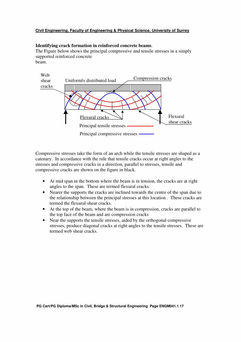
Identifying crack formation in reinforced concrete beams.
The Figure below shows the principal compressive and tensile stresses in a simply
supported reinforced concrete
beam.
Compressive stresses take the form of an arch while the tensile stresses are shaped as a
catenary. In accordance with the rule that tensile cracks occur at right angles to the
stresses and compressive cracks in a direction, parallel to stresses, tensile and
compressive cracks are shown on the figure in black.
• At mid span in the bottom where the beam is in tension, the cracks are at right angles to the span. These are termed flexural cracks.
• Nearer the supports the cracks are inclined towards the centre of the span due to
the relationship between the principal stresses at this location . These cracks are
termed the flexural-shear cracks.
• At the top of the beam, where the beam is in compression, cracks are parallel to
the top face of the beam and are compression cracks
• Near the supports the tensile stresses, aided by the orthogonal compressive
stresses, produce diagonal cracks at right angles to the tensile stresses. These are
termed web shear cracks.
Uniformly distributed load
Principal compressive stresses
Principal tensile stresses
Web
shear
cracks
Flexural cracks Flexural
shear cracks
Compression cracks
Civil Engineering, Faculty of Engineering & Physical Science, University of Surrey
PG Cert/PG Diploma/MSc in Civil, Bridge & Structural Engineering Page ENGM041.1.18
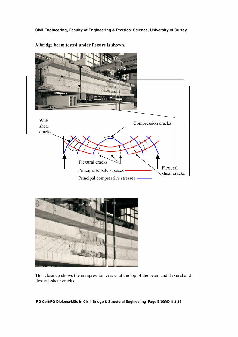
A bridge beam tested under flexure is shown.
This close up shows the compression cracks at the top of the beam and flexural and
flexural-shear cracks.
Principal compressive stresses
Principal tensile stresses
Web
shear
cracks
Flexural cracks
Flexural
shear cracks
Compression cracks

Civil Engineering, Faculty of Engineering & Physical Science, University of Surrey
PG Cert/PG Diploma/MSc in Civil, Bridge & Structural Engineering Page ENGM041.1.19
Principles of reinforced concrete design.
Aims of Design.
The aim of Reinforced Concrete design is to ensure that :-
1. with an appropriate degree of reliability, the structure will sustain all loads and
external influences likely to occur during construction, and subsequent
occupation. It should also have adequate durability to keep maintenance costs at a
minimum. (ultimate limit state and durability)
2. with acceptable probability, the structure will remain fit for the use for which it is
required – keeping in mind the intended life of the structure and its costs.
(serviceability limit state).
3. the structure will remain ft for the use for which it is required and will not be
damaged by events such as explosions, impact or accidents “to an extent
disproportionate to the original cause”. (robustness).
These requirements can be achieved by :-
1. making a suitable choice of materials,
2. paying proper attention to design and detailing and
3. specifying control procedures for all stages of design and construction.
Future requirements for designers are likely to include :-
1. The need to design for demolition as well as construction.
2. The need to consider sustainability issues. i.e. it will be incumbent on the
designer to consider the initial cost of the building or structure, the cost of heating
and cooling the building during occupation and techniques to minimise energy
usage during the life of the structure and the cost of demolition, all at the concept
stage.
Limit states.
Definition. A limit state is defined as states beyond which the structure no longer
satisfies the performance requirements of the design and are classified as :-
1. Ultimate Limit state. (ULS).
These are associated with collapse or other forms of structural damage likely to
endanger life. They include:
• Loss of equilibrium of the structure or any part of it considered as a rigid
body.
• Failure by

Civil Engineering, Faculty of Engineering & Physical Science, University of Surrey
PG Cert/PG Diploma/MSc in Civil, Bridge & Structural Engineering Page ENGM041.1.20
o Excessive deformation
o Transformation of the structure or any part of it into a mechanism.
o Rupture
o Loss of stability of the structure or any part of it, including supports and
foundations.
o Fatigue or other time dependant effects.
The ultimate limit state should ensure structures are designed so that adequate means
exist to transmit the design ultimate dead, imposed and wind loads safely from the
highest support to the foundations. Robustness within a structure is required to prevent
disproportionate failure or collapse and as such may be considered an ultimate limit state.
Robustness.
Structures should include in the design a degree of robustness. For example, they should
not be unreasonably susceptible to the effects of accidents or explosions.
An important gas explosion in the1960’s illustrates the importance of the ULS. It
occurred on the 20th storey of a block of flats in London called Ronan Point. Instead of
merely blowing out the windows and causing local damage to the flat where the
explosion occurred, the walls were dislodged and since the floor above could not act as a
cantilever and so support itself, it collapsed onto the floor below so overloading it and
this in turn collapsed onto the floor below causing progressive failure downwards. In
addition, the floors above collapsed as some of their support had been removed and they
were not sufficiently “robust” to survive.
Ronan Point – Progressive collapse
Civil Engineering, Faculty of Engineering & Physical Science, University of Surrey
PG Cert/PG Diploma/MSc in Civil, Bridge & Structural Engineering Page ENGM041.1.21
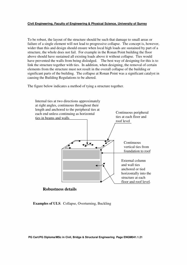
To be robust, the layout of the structure should be such that damage to small areas or
failure of a single element will not lead to progressive collapse. The concept is, however,
wider than this and design should ensure when local high loads are sustained by part of a
structure, the whole does not fail. For example in the Ronan Point building the floor
above should have sustained all existing loads above it without collapse. Ties would
have prevented the walls from being dislodged. The best way of designing for this is to
link the structure together with ties. In addition, when designing, the removal of certain
elements from the structure must not result in the overall collapse of the building or
significant parts of the building. The collapse at Ronan Point was a significant catalyst in
causing the Building Regulations to be altered.
The figure below indicates a method of tying a structure together.
Examples of ULS. Collapse, Overturning, Buckling
External column
and wall ties
anchored or tied
horizontally into the
structure at each
floor and roof level.
Internal ties at two directions approximately
at right angles, continuous throughout their
length and anchored to the peripheral ties at
each end unless continuing as horizontal
ties in beams and walls
Continuous peripheral
ties at each floor and
roof level
Continuous
vertical ties from
foundation to roof
Robustness details

Civil Engineering, Faculty of Engineering & Physical Science, University of Surrey
PG Cert/PG Diploma/MSc in Civil, Bridge & Structural Engineering Page ENGM041.1.22
2. Serviceability Limit state (SLS)
These are concerned with the functioning of the structure under normal use, the
comfort of the people using the structure, the appearance of the structure and damage
to finishes or non structural members. They include :-
o deformations affecting the appearance, user’s comfort or effective use
of the structure.
o vibrations limiting the effective use of the structure or affecting user’s
comfort.
o cracking of the concrete affecting adversely the appearance, durability
or water tightness of the structure.
Serviceability limit states are just as important as ultimate limit states and are often the
controlling factor in design. For example it is deflection limits, not strength that control
how most slabs will span and indeed the span / depth ratio of many beams, governs the
design, not ULS.
The following effects can all influence how a structure performs often affecting the
serviceability. In most cases, however, appropriate design loads, well specified material
properties, slenderness limits and other simple rules allow for them.
• Creep
• Sway
• Shrinkage
• Settlement
• Temperature
• Cyclic loading.
Serviceability criteria govern the deflection and deformation of a structure and in this
respect, should not adversely affect its efficiency or appearance. Deflections should be
compatible with the movements acceptable by the component parts. eg. Finishes,
services, partitions, glazing and cladding.
For tall slender structures, the effect of lateral deflections should be considered.
However, the accelerations associated with the deflections may be more critical as these
are what the occupants will notice.
Cracking will always occur in reinforced concrete. Generally this is not a sign of failure
but the widths of these cracks must be limited, to ensure water and other deleterious
substances do not penetrate the concrete and cause corrosion of the reinforcement but
also as they must not be visible to the general public from say a meter or so away. Rules
exist in the codes which enable the widths of the cracks to be controlled through
including secondary reinforcement.
SLS. Deformation, Cracking, Vibration.
Civil Engineering, Faculty of Engineering & Physical Science, University of Surrey
PG Cert/PG Diploma/MSc in Civil, Bridge & Structural Engineering Page ENGM041.1.23
Durability of concrete.
Concrete durability is largely affected by how the structure performs under service loads.
Consider, for example, crack widths which are directly related to reinforcement
corrosion. The consequences of durability, though, can have repercussions on the
ultimate limit state if deterioration progresses significantly.
It is important to ensure all concrete elements are sufficiently durable. For a concrete
element to be durable it must be designed and constructed to protect the embedded
reinforcement from corrosion and generally to perform in a satisfactory manner in the
environment it is placed in and for the design life of the structure. Durability mainly
affects the reinforcement embedded within the concrete, but there are instances when the
concrete itself is affected and degrades. For example, certain types of ground sulphates
(or even pollutants with particular sulphates in them) can cause expansive reactions in
concrete significantly weakening it. Further, certain alkalis which are sometimes found
in the aggregate used to manufacture concrete have similar effects. Fortunately, both
these problems are rare in this region.
The concrete environment.
The environment in which concrete finds itself refers to any chemical or physical
reactions to which the structure as a whole, individual elements of the structure, or the
concrete itself is exposed and which may result in effects not included in the loading
conditions considered at the structural design stage. Inadequate attention to the durability
at the design and construction stages may subsequently lead to considerable expenditure
on inspection, maintenance and repair. Consequently, durability has gained in
importance in all codes over the years.
Corrosion of Reinforcement.
Steel reinforcement embedded in concrete is surrounded by a highly alkaline pore
solution with a pH value in excess of 12.5. Such an alkaline environment causes the steel
to be passivated, i.e. a highly impermeable oxide layer forms on the surface of the steel
which protects it from corrosion. Corrosion of steel reinforcement is likely to occur
when loss of passivity takes place, which is usually due to carbonation or chloride
ingress.
Carbonation ingress.
Acidic gases like carbon dioxide combine with water to form weak solutions of carbonic
acid which is washed over the surface of the concrete usually as a result of rain. This
acid reacts with parts of the concrete to de-passivate it and turn it acidic. Over time the
acidic front penetrates deeper into the concrete and if it reaches the reinforcement can
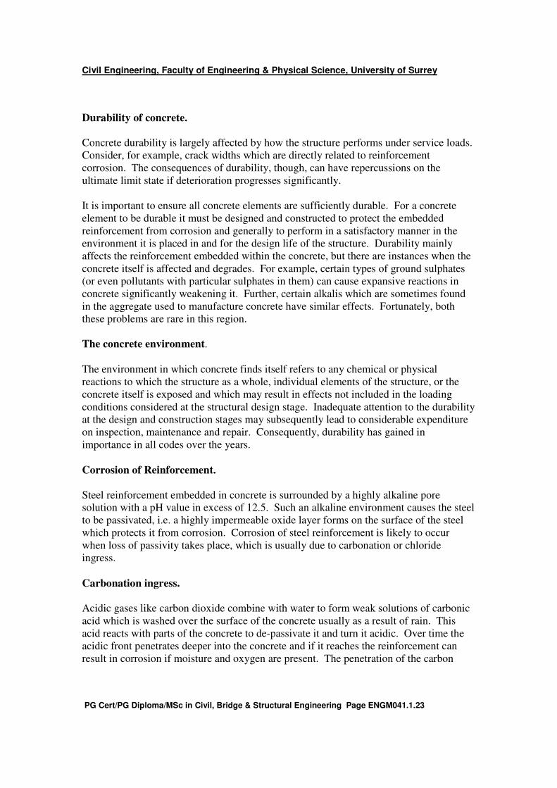
result in corrosion if moisture and oxygen are present. The penetration of the carbon
Civil Engineering, Faculty of Engineering & Physical Science, University of Surrey
PG Cert/PG Diploma/MSc in Civil, Bridge & Structural Engineering Page ENGM041.1.24
front has been observed to be proportional to (time)0.5
. The Figure below indicates early
and later stages of carbonation.
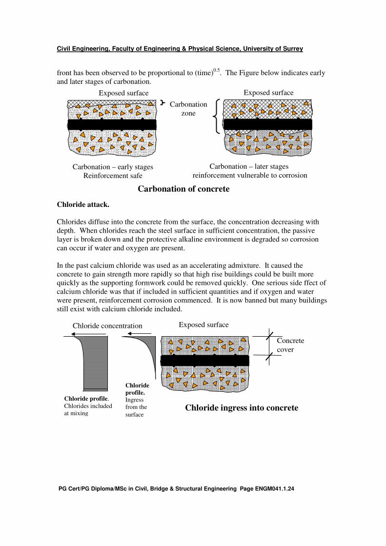
Chloride attack.
Chlorides diffuse into the concrete from the surface, the concentration decreasing with
depth. When chlorides reach the steel surface in sufficient concentration, the passive
layer is broken down and the protective alkaline environment is degraded so corrosion
can occur if water and oxygen are present.
In the past calcium chloride was used as an accelerating admixture. It caused the
concrete to gain strength more rapidly so that high rise buildings could be built more
quickly as the supporting formwork could be removed quickly. One serious side ffect of
calcium chloride was that if included in sufficient quantities and if oxygen and water
were present, reinforcement corrosion commenced. It is now banned but many buildings
still exist with calcium chloride included.
Chloride concentration
Concrete
cover
Chloride ingress into concrete
Exposed surface
Chloride
profile. Ingress
from the
surface
Chloride profile.
Chlorides included
at mixing
Exposed surface Exposed surface
Carbonation
zone
Carbonation – early stages
Reinforcement safe
Carbonation – later stages
reinforcement vulnerable to corrosion
Carbonation of concrete
Civil Engineering, Faculty of Engineering & Physical Science, University of Surrey
PG Cert/PG Diploma/MSc in Civil, Bridge & Structural Engineering Page ENGM041.1.25
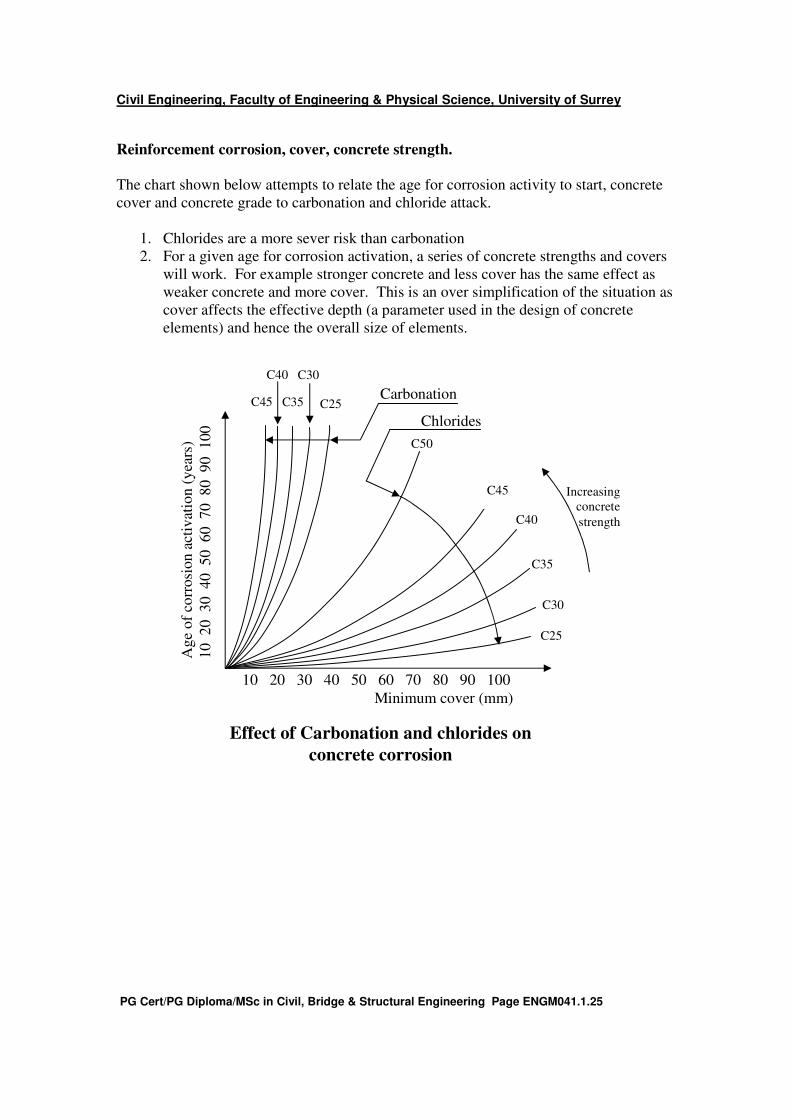
Reinforcement corrosion, cover, concrete strength.
The chart shown below attempts to relate the age for corrosion activity to start, concrete
cover and concrete grade to carbonation and chloride attack.
1. Chlorides are a more sever risk than carbonation
2. For a given age for corrosion activation, a series of concrete strengths and covers
will work. For example stronger concrete and less cover has the same effect as
weaker concrete and more cover. This is an over simplification of the situation as
cover affects the effective depth (a parameter used in the design of concrete
elements) and hence the overall size of elements.
Increasing
concrete
strength
C25
C30
C35
C40
C50
10 20 30 40 50 60 70 80 90 100
Minimum cover (mm)
Ag
e o
f co
rrosi
on
act
ivat
ion
(y
ears
)
10
20
30
40
50
60
70
80
90
100
C45
C40
C35
C30
C25 Carbonation
C45
Chlorides
Effect of Carbonation and chlorides on
concrete corrosion
Civil Engineering, Faculty of Engineering & Physical Science, University of Surrey
PG Cert/PG Diploma/MSc in Civil, Bridge & Structural Engineering Page ENGM041.1.26
Alkali aggregate reaction (AAR).
Three forms of this reaction occur
1. Alkali-silica reaction (ASR). This is the most common form
2. Alkali-silicate.
3. Alkali- carbonate.
This reaction is an expansive reaction that can cause cracking and disruption of the
concrete. AAR is a reaction within the concrete unlike most durability problems which
are associated with reinforcement deterioration.
For AAR to occur all three of the following conditions must be met.
1. Sufficient moisture within the concrete
2. The concrete must have a high alkali content – alkali sources can be internal
arising from cement, water, chemical admixtures, and some aggregates or external
through exposure to sea water.
3. The aggregate must contain an akali reactive constituent. Some aggregates
containing particular varieties of silica are susceptible to attack from alkalis.
Alkali aggregate reaction is relatively rare in the UK and where past experience with
particular cement / aggregate combinations indicates no tendency to the reaction,
precautions need not be taken. If, however, unfamiliar materials are being used, there
may be a risk and additional testing or access to the national database on aggregates
should be made.
To minimize risk of AAR occurring :-
1. Limit the alkali content of the mix.
2. Use a cement with a low effective alkali content.
3. Change the aggregate to one which is known to be low risk.
4. Limit the degree of saturation or moisture content of the concrete when hardened
by using for example, impermeable membranes.
Sulphate attack.
Normally concrete is only at risk from sulphates if it is buried as it is the sulphates
present in ground water which cause degradation to the concrete. So foundations and
retaining walls for example are at risk. In addition, in areas with high atmospheric
pollution airborne suphates can cause degradation to the concrete if they are washed over
the concrete by rain over a long period of time.
Sulphates are, however, present in most cements and in some aggregates and excessive
amounts of water-soluble sulphates from these sources can be deleterious to concrete.
Sulphate attack in concrete is expansive and again affects the concrete itself.

Civil Engineering, Faculty of Engineering & Physical Science, University of Surrey
PG Cert/PG Diploma/MSc in Civil, Bridge & Structural Engineering Page ENGM041.1.27
The water soluble sulphate content (SO3) of the concrete mix should not exceed 4% by
mass of the cement in the mix. The sulphate content is calculated as the total obtained
from the various constituents of the mix.
Sulphate attack can often be offset by using sulphate resisting cement. Even using this
cement which has the ingredients likely to react with sulphates removed from it, is not
100% reliable. In association with sulphate resisting cements, good compaction and
quality control is necessary. Binary cements – those which contain pfa or ggbs are more
sulphate resistant than conventional Portland cements.
Durability and design.
Designing for strength is relatively straight forward but designers need to be aware of the
long term requirements of building and consider durability. To assess the degree of
durability required designers should consider at least the following :-
• Intended use of the structure. Designers need to view a nuclear power station
differently from a garden path. Consider a situation where many “heavy metal
rock” fans are dancing on a balcony in a purpose built venue and a car parking
garage. Different needs exist in the different situations and design will be
influenced by these.
• Required performance criteria. Using the nuclear power station and the garden
path example again. Clearly very high performance criteria are consistently
needed in the former as a failure will be catastrophic whilst in the garden path
failure will be unlikely to affect anyone’s life.
• Expected environmental conditions. Concrete protection will vary, depending on
the environment. A sea wall exposed to splash will need greater protection than
say the internal beam in a department store.
• Composition, properties and performance of materials. Durability is affected by
the aggregate and cement type and in some instances by the water used in the
concrete. These factors need to be considered at the design stage.
• Shape of members and structural detailing. Designers have the ability to
influence the architectural details to some extent. Good detailing is essential to
reduce maintenance costs.
• Quality of workmanship and level of supervision. This is obvious but sometimes
difficult to implement. The construction phase is very pressured and quality
control is important. A well built structure will always be more durable than a
poorly built one.
• Particular protective measures. Designers can reduce degradation of reinforced
concrete by including targeted protective measures. For example, waterproof
membranes can be included to prevent groundwater from saturating concrete.
Good detailing can prevent concrete from being periodically wetted.
• Likely maintenance during the intended life. Clients will want the best of both
worlds. Low build and zero maintenance costs. There is always a cost
implication in the long term if construction costs are cut.
Civil Engineering, Faculty of Engineering & Physical Science, University of Surrey
PG Cert/PG Diploma/MSc in Civil, Bridge & Structural Engineering Page ENGM041.1.28
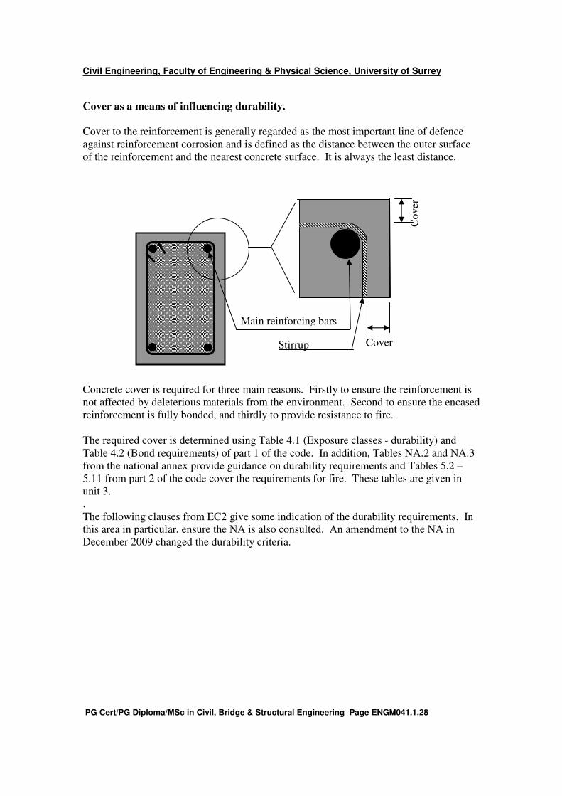
Cover as a means of influencing durability.
Cover to the reinforcement is generally regarded as the most important line of defence
against reinforcement corrosion and is defined as the distance between the outer surface
of the reinforcement and the nearest concrete surface. It is always the least distance.
Concrete cover is required for three main reasons. Firstly to ensure the reinforcement is
not affected by deleterious materials from the environment. Second to ensure the encased
reinforcement is fully bonded, and thirdly to provide resistance to fire.
The required cover is determined using Table 4.1 (Exposure classes - durability) and
Table 4.2 (Bond requirements) of part 1 of the code. In addition, Tables NA.2 and NA.3
from the national annex provide guidance on durability requirements and Tables 5.2 –
5.11 from part 2 of the code cover the requirements for fire. These tables are given in
unit 3.
.
The following clauses from EC2 give some indication of the durability requirements. In
this area in particular, ensure the NA is also consulted. An amendment to the NA in
December 2009 changed the durability criteria.
Co
ver
Cover
Main reinforcing bars
Stirrup

Civil Engineering, Faculty of Engineering & Physical Science, University of Surrey
PG Cert/PG Diploma/MSc in Civil, Bridge & Structural Engineering Page ENGM041.1.29
4.1 Durability requirements
4.1.0 Notation (See also 1.6 and 1.7)
dg - Largest nominal maximum aggregate size
∆h - Tolerance on cover to reinforcement (difference between minimum and nominal
cover)
Φ - Diameter of a reinforcing bar, diameter of a tendon or of a prestressing duct
Φn - Equivalent diameter of a bundle of reinforcing bars.
4.1.1 General
P(1) The requirement of an adequately durable structure is met if, throughout its required
life, a structure fulfils its function with respect to serviceability, strength and stability
without significant loss of utility or excessive unforeseen maintenance.
P(2) To provide the required overall durability, as defined in P(1) above, the intended use
of the structure shall be established, together with the load specifications to be
considered. The required life of the structure and the maintenance programme shall also
be considered, in assessing the level of protection required.
P(3) Durability may be affected both by direct actions and also by consequential indirect
effects inherent in the performance of the structure (e.g. deformations, cracking, water
absorption, etc). The possible significance of both direct and indirect effects shall be
considered.
(4) For most buildings, the general provisions in this Code will ensure a satisfactory life.
However, the required level of performance — and its duration — should be considered
consciously, at an early stage in the design. Modifications to the recommended measures
may be required in certain circumstances, e.g. for temporary or monumental structures, or
for structures subjected to extreme or unusual actions (either direct or indirect effects —
see P(3) above).
4.1.2 Actions
4.1.2.1 General
P(1) Actions shall be assessed in accordance with the definitions given in 2.2.2 and based
on values given in appropriate international or national codes. In special cases, it may be
necessary to consider modification of these values to meet particular durability
requirements.
4.1.2.2 Environmental conditions
P(1) Environment, in this context, means those chemical and physical actions, to which
the structure as a whole, the individual elements, and the concrete itself is exposed, and
which results in effects not included in the loading conditions considered in structural
design.
(2) For the design of normal buildings, environmental conditions should be classified in
accordance with Table 4.1, to establish the overall level of protection required in
accordance with the provisions of ENV 206.
(3) In addition, it may be necessary to consider certain forms of aggressive or indirect
action individually (see 4.1.2.3, 4.1.2.4, 4.1.2.5).
Civil Engineering, Faculty of Engineering & Physical Science, University of Surrey
PG Cert/PG Diploma/MSc in Civil, Bridge & Structural Engineering Page ENGM041.1.30
4.1.2.3 Chemical attack
P(1) The effects of chemical attack shall be considered in design.
P(2) Consideration shall be given to the effects of chemical attack both on the concrete
and any embedded metal.
(3) Chemical attack may arise from:
— the use of the building (storage of liquids, etc);
— an aggressive environment (see Table 4.1 and ENV 206, Clause 6.2);
— contact with gases or solutions of many chemicals, but usually from exposure to acidic
solutions or to solutions of sulphate salts (see ENV 206, Table 3 and ISO 9690);
— chlorides contained in the concrete (see 5.5 in ENV 206 for the permitted maxima);
— reactions between the materials in the concrete (e.g. alkali-aggregate reaction, see 5.7
in ENV 206 and National Standards).
— (4) For most buildings, adverse chemical reactions can be avoided by adopting an
appropriate material specification, e.g. the provisions in ENV 206, to achieve a dense
impermeable concrete with appropriate mix ingredients and properties (see Table 3, ENV
206). In addition, adequate cover is required to protect the reinforcement (see 4.1.3.3).
4.1.2.4 Physical attack
P(1) The effects of physical attack shall be considered in design.
(2) Physical attack can occur because of:—
— abrasion (see 7.3.1.4 in ENV 206);
— freeze-thaw action (see ENV 206, Table 3);
— water penetration (see Table 3 and 7.3.1.5 in ENV 206).
(3) For most buildings, physical attack can be resisted through an appropriate material
specification, e.g. the provisions of ENV 206, combined with an appropriate limitation of
cracking under the relevant load combination (see 4.4.2).
4.1.2.5 Consequential indirect effects
P(1) Deformation of the structure as a whole, of individual structural elements or non-
load bearing elements (e.g. due to imposed loads, temperature, creep, shrinkage, micro-
cracking, etc.) can lead to consequential indirect effects, and these shall be considered in
design.
(2) For most buildings, the influence of indirect effects can be accommodated by
complying with general requirements, given elsewhere in this Code, for durability,
cracking, deformation, detailing, — and for strength, stability and robustness of the
structure as a whole. Additionally, consideration may have to be given to the
following:—
— minimising deformation and cracking due to time-dependent factors (e.g. early-age
movement, creep, shrinkage, etc) — see 3.1;
— minimising restraints due to deformation (e.g. by the provision of bearings or joints,
while ensuring that these do not permit the ingress of aggressive agents);
— if restraints are present, ensuring that any significant effects are taken into account in
design.
Civil Engineering, Faculty of Engineering & Physical Science, University of Surrey
PG Cert/PG Diploma/MSc in Civil, Bridge & Structural Engineering Page ENGM041.1.31
4.1.3 Design
4.1.3.1 General
P(1) Early in the design process, the effects, and possible significance, of the actions in
4.1.2 shall be considered in relation to the durability requirement in 4.1.1.
(2) For most buildings, reference should be made to the design criteria in 4.1.3.2 and to
the requirements for concrete cover to reinforcement in 4.1.3.3 and to the general
material and construction factors in 4.1.4 and 4.1.5.
(3) Other factors to be considered in design and detailing, in order to achieve the required
level of performance, should include the following:—
— the adoption of a structural form which will minimise the uptake of water or exposure
to moisture.
— the size, shape and design details of exposed elements or structures should be such as
to promote good drainage and to avoid run off or standing pools of water. Care should be
taken to minimise any cracks that may collect or transfer water. In the presence of cracks
crossing a complete section and likely to transport water containing chlorides, additional
protective measures (coated bars, coatings, etc.) may be necessary.
— attention, in design and detailing, to the different aspects of indirect effects (see
4.1.2.5);
— for most components in buildings, resistance to reinforcement corrosion is provided
by having an adequate cover of low-permeability, good-quality concrete (see 4.1.3.3 and
ENV 206). For the more severe conditions of exposure (see Table 4.1), consideration
may need to be given to protective barriers either to the concrete surface or to the
reinforcement.
4.1.3.2 Design criteria
P(1) To produce a durable concrete, the requirements primarily of chapters 2 and 3 of this
document, shall be met, together with those of ENV 206 — while considering local
conditions, materials and practices.
P(2) For reinforced concrete corrosion protection to reinforcement shall be provided by
compliance with the requirements contained in the following clauses:
4.4.1 stress conditions
4.4.2 cracking
4.4.3 deformation
4.1 (and ENV 206) general durability requirements
4.1.3.3 concrete cover
P(3) For prestressed concrete, in addition to the requirements in P(1) and P(2) above, the
prestressing steel shall be protected from all aggressive actions.
(4) For exposure classes 1–4, prestressed sections should be checked for cracking in
accordance with 4.4.2.1(7) and 4.4.2.2(5) – (8).

Civil Engineering, Faculty of Engineering & Physical Science, University of Surrey
PG Cert/PG Diploma/MSc in Civil, Bridge & Structural Engineering Page ENGM041.1.32
4.1.3.3 Concrete cover
P(1) The concrete cover is the distance between the outer surface of the reinforcement
(including links and stirrups) and the nearest concrete surface.
P(2) A minimum concrete cover shall be provided in order to ensure:
— the safe transmission of bond forces;
— that spalling will not occur;
— an adequate fire resistance;
— the protection of the steel against corrosion (see P(3) below and ENV 206).
P(3) The protection of reinforcement against corrosion depends upon the continuing
presence of a surrounding alkaline environment provided by an adequate thickness of
good quality, well-cured concrete. The thickness of cover required depends both upon
the exposure conditions and on the concrete quality.
P(4) The minimum concrete cover required for the criterion in P(3) above shall first be
determined. This shall be increased by an allowance (∆h) for tolerances, which is
dependent on the type and size of structural element, the type of construction, standards
of workmanship and quality control, and detailing practice. The result is the required
nominal cover which shall be specified on the drawings.
P(5) To transmit bond forces safely, and to ensure adequate compaction, the concrete
cover, to the bar or tendon being considered, should never be less than:
— Φ or Φn
— or (Φ + 5 mm) or (Φn + 5 mm) if dg > 32 mm
where:
Φ - is the diameter of the bar, diameter of a tendon or of the duct (post-tensioning)
Φn - is the equivalent diameter for a bundle
dg - is the largest nominal maximum aggregate size.
Reference should also be made to 5.4 in ENV 206.
P(6) The minimum concrete cover to all reinforcement including links and stirrups should
not be less than the appropriate values given in Table 4.2, for the relevant exposure class
defined in Table 4.1.
P(7) Where surface reinforcement is used (see 5.4.2.4), the cover should either comply
with (6) above, or special protective measures should be taken (e.g. protective coatings).
P(8) The allowance (∆h) for tolerances will usually be in the range |0 mm ≤ ∆h ≤ 5 mm|,
for precast elements, if production control can guarantee these values and if this is
verified by quality control. The allowance will be in the range |5 mm ≤ ∆h ≤ 10 mm| for
insitu reinforced concrete construction. Additional rules for construction and
workmanship (including tolerances) are given in chapter 6 of the code.
P(9) For concrete cast against uneven surfaces, the minimum covers given in Table 4.2
should generally be increased by larger tolerances. For example, for concrete cast directly
against the earth, the minimum cover should be greater than |75 mm|; for concrete cast
against prepared ground (including blinding) the minimum cover should be greater than
|40 mm| surfaces having design features, such as ribbed finishes or exposed aggregate,
also require increased cover.
P(10) The required minimum covers given in Table 4.2, as modified to allow for
tolerances, may be insufficient for fire protection. Particular requirements for fire
resistance are given in separate documents.
Civil Engineering, Faculty of Engineering & Physical Science, University of Surrey
PG Cert/PG Diploma/MSc in Civil, Bridge & Structural Engineering Page ENGM041.1.33
P(11) For pre-tensioned members, the minimum cover should not be less than 2Φ, where
Φ is the diameter of a tendon. Where ribbed wires are used, the minimum cover should
not be less than 3 Φ.
P(12) For post-tensioned members, the minimum cover is to the duct. The cover should
be not less than the diameter of the duct. For rectangular ducts, the cover should be not
less than the lesser dimension of the duct cross-section nor half the greater dimension.
4.1.4 Materials
P(1) Materials shall comply with the requirements of appropriate international or national
standards. The choice of materials shall be made, taking account of the environmental
conditions including any aggressive actions. These should be considered in conjunction
with other factors such as design and detailing, standards of workmanship and
construction, and intended maintenance regimes — to produce the required level of
performance for the structure throughout its service life.
(2) For concrete the requirements should generally be in accordance with ENV 206.
These requirements relate to the constituents and composition of the mix and to the
processes involved in mixing, transporting, placing, compacting and curing the concrete
in the structure.
(3) For reinforcement, the requirements of 3.2 apply.
(4) For prestressing steel, the requirements of 3.3 apply.
(5) For anchorage devices, the requirements of 3.4 apply. For exposure classes 2 – 5, any
anchorage or fixing device which is not fully embedded in the concrete may have to be
protected against corrosion by special measures.
(6) Other materials may be used, provided that full account is taken of their effects on
design requirements and that there are satisfactory data on their suitability and quality.
4.1.5 Construction
P(1) The standard of workmanship on site shall be such as to ensure that the required
durability of the structure will be obtained. The combination of materials and procedures
used in making, placing and curing the concrete shall be such as to achieve satisfactory
resistance to aggressive media for both concrete and steel.
P(2) During construction, adequate measures shall be taken, by means of supervision and
quality control, to ensure that the required properties of the materials and standards of
workmanship are achieved.
(3) The requirements for workmanship are given in chapter 6 of the code and in ENV
206.
Civil Engineering, Faculty of Engineering & Physical Science, University of Surrey
PG Cert/PG Diploma/MSc in Civil, Bridge & Structural Engineering Page ENGM041.1.34
Fire design.
The structural design for fire is covered in BS EN 1992 – 1 – 2 and its associated
National Annex. The behaviour of the structure exposed to fire is assessed by either :
• Modelled fire exposure or
• Nominal fire exposure, which uses a standard model for which tabulated data for
fire resistance is provided.
This course only covers the second point, not fire testing.
Building Regulation requirements regarding internal fire spread fall into three categories
:-
Resistance to load bearing elements, R (stability)
Resistance to fire penetration, E (integrity)
Resistance to transfer of excessive heat, I (insulation).
In England and Wales the Building regulations specify the period of fire resistance which
the structure and its elements must provide. This ranges from 30 – 240 minutes,
depending on the use of the structure, to allow occupants to evacuate the building and to
enable fire fighters to deal with the blaze in safety. Standard fire resistances are
expressed by their category identifiers and the number of minutes. For example, - R120,
EI60 (non-loadbearing), REI240, etc.
The resistance of reinforced concrete to fire depends on
• The concrete cover to the reinforcement.
• The member thickness
• The type and quality of all materials and workmanship.
Concrete covers that satisfy bond and durability requirements may not give adequate
resistance to fire.
The fire resistance of columns and walls will be based on the estimated capacity of the
element when burning and the load it sustains in the fire. As a simplification and to avoid
an extra analysis, design actions for fire design may be related to the ULS values by a
reduction factor, ηfi, as follows
Ed,fi = ηfi Ed
Where, E in the code represents the effect of an action.
So for example, with axial loads,
Nd,fi = ηfi Nd
Civil Engineering, Faculty of Engineering & Physical Science, University of Surrey
PG Cert/PG Diploma/MSc in Civil, Bridge & Structural Engineering Page ENGM041.1.35
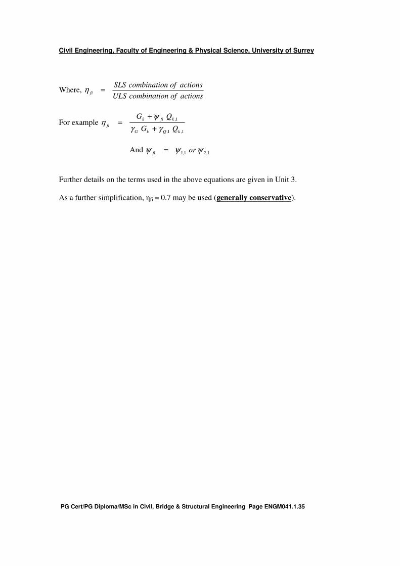
Where, actionsofncombinatioULS
actionsofncombinatioSLSfi =η
For example 1,1,
1,
kQkG
kfik
fiQG
QG
γγ
ψη
+
+=
And 1,21,1 ψψψ orfi =
Further details on the terms used in the above equations are given in Unit 3.
As a further simplification, ηfi = 0.7 may be used (generally conservative).

Civil Engineering, Faculty of Engineering & Physical Science, University of Surrey
PG Cert/PG Diploma/MSc in Civil, Bridge & Structural Engineering Page ENGM041.1.36
The economic and environmental case for concrete framed buildings.
Which material?
Frame cost should not dictate the choice of frame material. Rather it should be just one of
a number of issues that should be considered when making the choice. Only then can one
be confident that the best and optimum structural solution is achieved. The following
checklist should assist designers and cost consultants to achieve the best value solution.
Frame costs
The recent rises in reinforcement and steel prices have increased frame costs but the
difference between the costs of steel and concrete frames still remains insignificant.
Steel v Concrete: the impact of recent price rises.
A 50% increase in European steel prices during 2004 left many in the construction
industry reviewing design solutions that have a heavy reliance on steel. A study by
leading construction economists Franklin + Andrews* examining the impact of the steel
price rises has found that the whole project costs for concrete framed buildings are
marginally less than for steel framed buildings. Since 2004, steel costs dropped but
Chinese demand is recreating the picture seen in 2004.
Costs are for the 2nd quarter of 2004.
Concrete Steel
3-storey £5,107,845 £5,190,067
7-storey £10,796,986 £10,962,115
* Economic Bulletin Volume 7. 2 , July 2004, Franklin + Andrews
Foundation costs.
Foundations typically represent approximately 3% of whole project initial cost. For the
heavier reinforced concrete solution, the foundations will be more expensive, but this still
only represents a small proportion of total cost and can be offset by using post-tensioned
slabs typically 15% lighter.
Cladding costs.
The thinner the overall structural and services zone, the less the cladding costs. Given
that cladding can represent up to 25% of the construction cost it is worth minimising the
cladding area. The minimum floor-to-floor height is almost always achieved with a
concrete flat slab and separate services zone.
Civil Engineering, Faculty of Engineering & Physical Science, University of Surrey
PG Cert/PG Diploma/MSc in Civil, Bridge & Structural Engineering Page ENGM041.1.37
Partitions
Sealing and fire stopping at partition heads is simplest with flat soffits. Significant
savings of up to 10% of the partitions package can be made compared to the equivalent
dry lining package abutting a profiled soffit with downstands. This can represent up to
4% of the frame cost.
Air tightness
Part L of the Building Regulations now require pre-completion pressure testing. Failing
these tests means a time consuming process of inspecting joints and interfaces and then
resealing them where necessary. Concrete edge details are simpler to seal and have less
risk of failure. Some contractors have switched to concrete frames on this criterion alone.
Services co-ordination/ installation/adaptability
The soffit of a concrete flat slab provides a zone for services distribution free of any
downstand beams. This reduces coordination effort for the design team and therefore the
risk of errors. It permits flexibility in design and allows co-ordination effort to be focused
elsewhere. Services installation is simplest below a flat soffit. This permits maximum off
site fabrication of services, higher quality of work and quicker installation.
These advantages should be reflected in cost and value calculations. Indeed, M&E
contractors quote an additional cost of horizontal services distribution below a profiled
slab of up to 15%. Flat soffits also allow greater future adaptability. New layouts and
cellular arrangements plus different service requirements are straightforward.
Fire protection
For concrete structures fire protection is generally not needed as the material has inherent
fire resistance of up to 4 hours. This removes the time, cost and separate trade required
for fire protection.
Acoustics
To meet the more stringent Part E of the Building Regulations, additional finishings to
walls and floors are often required. The inherent mass of concrete means these additional
finishings are minimised or even eliminated.
Vibration
The inherent mass of concrete means that concrete floors generally meet vibration criteria
at no extra cost without any extra stiffening. For more stringent criteria, such as for
laboratories or hospital operating theatres, the additional cost to meet vibration criteria is
small compared to other structural materials.

Civil Engineering, Faculty of Engineering & Physical Science, University of Surrey
PG Cert/PG Diploma/MSc in Civil, Bridge & Structural Engineering Page ENGM041.1.38
Exposed soffit
A concrete structure has a high thermal mass. By exposing the soffits this can be utilised
through fabric energy storage (FES) to reduce initial plant costs and ongoing operational
costs. Furthermore, the cost of suspended ceilings can be reduced or eliminated.
Programme
Concrete frames have short lead-in times and with modern framework systems floor-to-
floor construction periods are reduced. Most CONSTRUCT members quote
500m2/week/crane on reasonably large and simple flat slab projects and more where
Hybrid Concrete Construction can be used.
For example, where precast columns are used in conjunction with post-tensioning, one-
week cycle times are possible. However, more important is whole project programme.
Concrete provides a safe working platform and semi-internal conditions so that services
installation and follow-on trades can commence early in the programme. And concrete
has the flexibility to accommodate design changes later in the process.
Net lettable area
The difference in net lettable area provided by different solutions for a building can be of
significant value. Whilst concrete structures may have larger columns, finishing is not
necessarily required and typically columns below 0.25m2 are not deducted from net
lettable area. Reduction in column size can be achieved by the use of high strength
concrete.
Concrete structures have reduced floor-to-floor heights, hence fewer steps between floors
and less plan area. Alongside these, RC shear walls are narrower than braced steel
frames. Therefore, the stair/stability core area is minimised freeing up more net lettable
area.
Whole life value
Concrete's range of inherent benefits, fabric energy storage, fire resistance and sound
insulation means that concrete buildings tend to have lower operating costs and lower
maintenance requirements. This is an important consideration for owner-occupiers and
PFI consortia.

Civil Engineering, Faculty of Engineering & Physical Science, University of Surrey
PG Cert/PG Diploma/MSc in Civil, Bridge & Structural Engineering Page ENGM041.1.39
Hybrid construction
What is Hybrid Construction
Hybrid concrete construction marries together the advantages of precast and insitu
concrete construction with significant benefits. For example, the adoption of a hybrid
concrete frame instead of a composite steel frame on a shell-and core office project in
central London resulted in construction savings of 29 percent and a 13 percent increase in
net lettable floor area.
Utilising Hybrid Concrete construction.
The UK has been slow to realise the benefits of hybrid concrete construction (HCC),
despite the widely appreciated construction benefits. Until recently one barrier to its use
was the lack of guidance but this has now been addressed by The Concrete Centre's 'Best
Practice Guidance for Hybrid Concrete Construction'.
Further, reports such as ‘Accelerating Change’ from the Strategic Forum for Construction
and ‘Rethinking Construction’ by Egan, have focused attention on the need for the UK
construction industry to move on from its inherent conservatism, modernise and increase
efficiency.
Civil Engineering, Faculty of Engineering & Physical Science, University of Surrey
PG Cert/PG Diploma/MSc in Civil, Bridge & Structural Engineering Page ENGM041.1.40
In terms of costs, insitu reinforced concrete is commonly viewed as being the most
economic framing option while precast concrete promotes speed and factory quality.
Combining the two as a hybrid frame results in even greater construction speed, quality
and overall economy. Traditional formwork typically accounts for up to 40 percent of an
insitu frame costs. These costs can be significantly reduced by increasing the use of
precast concrete which has no on-site formwork requirement. This also reduces the
duration of operations critical to the overall construction programme. Precasting is not
constrained by site progress or conditions and can continue independently of on-site
operations. Some HCC techniques can remove the need for follow-on trades such as
ceilings and finishes further improving the programme. HCC also encourages speed of
construction by promoting increased buildability.
Concrete produces robust, and adaptable buildings that are inherently fire resistant,
vibration free and quiet. Exposure of the hybrid concrete frame can be used to exploit
concrete's inherent thermal properties to form naturally ventilated, low-energy buildings.
The finish and shape of the exposed units can also assist with even distribution of lighting
levels and the reduction of noise levels. Long spans can be easily achieved using large
units or by pre-stressing or post-tensioning.
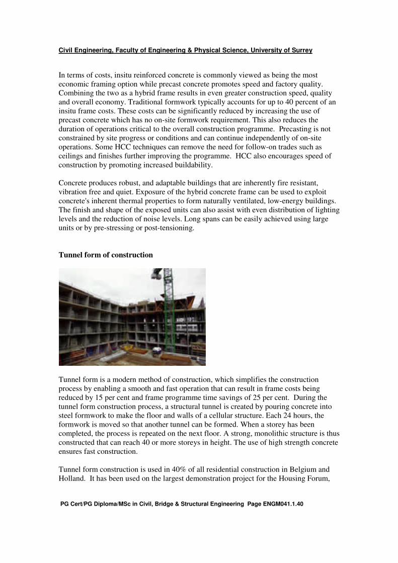
Tunnel form of construction
Tunnel form is a modern method of construction, which simplifies the construction
process by enabling a smooth and fast operation that can result in frame costs being
reduced by 15 per cent and frame programme time savings of 25 per cent. During the
tunnel form construction process, a structural tunnel is created by pouring concrete into
steel formwork to make the floor and walls of a cellular structure. Each 24 hours, the
formwork is moved so that another tunnel can be formed. When a storey has been
completed, the process is repeated on the next floor. A strong, monolithic structure is thus
constructed that can reach 40 or more storeys in height. The use of high strength concrete
ensures fast construction.
Tunnel form construction is used in 40% of all residential construction in Belgium and
Holland. It has been used on the largest demonstration project for the Housing Forum,
Civil Engineering, Faculty of Engineering & Physical Science, University of Surrey
PG Cert/PG Diploma/MSc in Civil, Bridge & Structural Engineering Page ENGM041.1.41
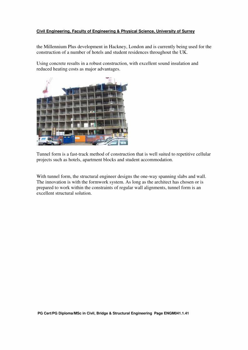
the Millennium Plus development in Hackney, London and is currently being used for the
construction of a number of hotels and student residences throughout the UK.
Using concrete results in a robust construction, with excellent sound insulation and
reduced heating costs as major advantages.
Tunnel form is a fast-track method of construction that is well suited to repetitive cellular
projects such as hotels, apartment blocks and student accommodation.
With tunnel form, the structural engineer designs the one-way spanning slabs and wall.
The innovation is with the formwork system. As long as the architect has chosen or is
prepared to work within the constraints of regular wall alignments, tunnel form is an
excellent structural solution.
Civil Engineering, Faculty of Engineering & Physical Science, University of Surrey
PG Cert/PG Diploma/MSc in Civil, Bridge & Structural Engineering Page ENGM041.1.42
Self assessment questions.
1. Why do we form reinforcement cages?
2. Discuss why we need cover to reinforcement from :
a. A mechanical design point of view.
b. A durability point of view
3. When a concrete cube is crushed, vertical cracks indicate the commencement of
failure. What sort of cracks are these? How does the cube actually fail?
4. Describe the process a reinforced concrete beam undergoes from first load until
collapse if :
a. It is under reinforced
b. It is over reinforced.
5. Discuss the benefits of a concrete framed building over the whole life of the
structure from sourcing materials to disposing of the structure. Consider
maintenance, embodied energy, running costs and demolition.
6. Define ultimate & serviceability limit states for reinforced concrete.
7. Why are structures designed to be robust? Discuss this in the context of Ronan
Point and the World Trade Centre collapses.
8. Modern codes recommend a series of ties in and around a building to improve
robustness. Why should this help? How and where should ties be positioned.
9. Modern codes require designers to consider durability. How can designers ensure
chloride ingress and carbonation effects do not reduce design life.
10. Consider similar reinforced concrete buildings being built in
a. North Scotland.
b. Lusaka, Zambia.
c. Riyadh in Saudi Arabia.
Make recommendations on how designers should approach each of the bullet
points below at the three locations. The bullet points are from durability and
design, earlier in Unit 1; repeated below. • Intended use of the structure. Designers need to view a nuclear power station differently from a garden path.
Consider a situation where many heavy metal fans are dancing on a balcony in a purpose built venue and a
car parking garage. Different needs exist in the different situations and design will be influenced by these.
• Required performance criteria. Using the nuclear power station and the garden path example again.. Clearly
very high performance criterial are consistently needed in the former as a failure will be catastrophic whilst in
the garden path failure will be unlikely to affect anyone’s life.
• Expected environmental conditions. Concrete protection will vary, depending on the environment. A sea
wall exposed to splash will need greater protection than say the internal beam in a department store.
• Composition, properties and performance of materials. Durability is affected by the aggregate and cement
type and in some instances by the water used in the concrete. These factors need to be considered at the
design stage.
• Shape of members and structural detailing. Designers have the ability to influence the architectural details to
some extent. Good detailing is essential to reduce maintenance costs.
• Quality of workmanship and level of supervision. This is obvious but sometimes difficult to implement. The
construction phase is very pressured and quality control is important. A well built structure will always be
more durable than a poorly built one.
• Particular protective measures. Designers can reduce degradation of reinforced concrete by including
targeted protective measures. For example, waterproof membranes can be included to prevent groundwater
from saturating concrete. Good detailing can prevent concrete from being periodically wetted.
• Likely maintenance during the intended life. Clients will want the best of both worlds. Low build and zero
maintenance costs. There ia always a cost implication in the long term if construction costs are cut.
11. What four factors need to be considered to determine cover to reinforcement. For
each factor outline a process to enable the cover required to be found.
Civil Engineering, Faculty of Engineering & Physical Science, University of Surrey
PG Cert/PG Diploma/MSc in Civil, Bridge & Structural Engineering Page ENGM041.1.43
Learning outcomes.
At the end of this unit you should be conversant with :
• The basic constituents of reinforced concrete.
• The fundamental aims of design and how various participants react to these.
• The behaviour of reinforced concrete beams from initial load to collapse.
• The different behaviours of over and under reinforced beams.
• Ultimate and Serviceability limit states.
• Robustness requirements.
• Preventing chloride and carbonation ingress from corroding reinforcement.
• The damage sulphate attack can inflict on concrete and how to abrogate this.
• Cover requirements for reinforcement in concrete with respect to environmental
factors, fire resistance, bonding reinforcement into concrete and other deviations.
• The relative benefits of steel and reinforced concrete frames.
• Hybrid and tunnel forms of construction.