backward curved pressure blowers - twin city fan azen · backward curved pressure blowers type bcn...
TRANSCRIPT
Twin City Bulletin 14501
backward curved pressure blowersTYpe bcN
Defining Innovation.
BULLETIN 1450-AMay 2011
Twin City Bulletin 14502
©2004 Twin City Fan Companies, Ltd. All rights reserved throughout the world.
Bulletin illustrations cover the general appearance of Twin City Fan & Blower products at the time of publication and we reserve the right to make changes in design and construction at any time without notice.
BCN Pressure BlowersThe BCN is a lower volume, higher pressure fan which utilizes a high efficiency, backward curved, non-overloading blade design. The BCN offers a lower specific speed design featuring single thickness blades, suitable for industrial processes involving clean as well as light particulate-laden air. Ruggedness of construction, reliability of operation, and stable air performance are the hallmarks of the BCN design.
Typical Applications• Combustion air• Pressure and vacuum drying• Product cooling• Primary air supply to ejectors• Liquid agitation• Glass blowing and cooling• Water blow-off• Air pollution control systems• Exhausting• Pneumatic conveying• Gas boosting
Choice of WheelsTwin City Fan offers two wheel designs. Fans desig-nated as sizes 270, 300, 330, etc. feature a narrower wheel for lower volumes with mechanical efficiencies to 80%. Fans designated as sizes 270W, 300W, 330W, etc. feature a wheel with slightly wider blades, a differ-ent blade profile and different blade count for relatively higher volumes while boosting mechanical efficiencies to 84%. Both wheels fit in a common BCN housing.
Capabilities• Available in arrangements 1, 4 and 8• Airstream temperatures to 800°F• Wheel diameters from 27" to 73"
Design “L”• Speeds to 1800 RPM• Sizes 270 to 730• Sizes 270W to 730W• Static pressures to 65" w.g.• Capacities to 75,000 CFM
Design “H”• Speeds to 3600 RPM• Sizes 270 to 402• Sizes 270W to 402W• Static pressures to 100" w.g.• Capacities to 35,000 CFM
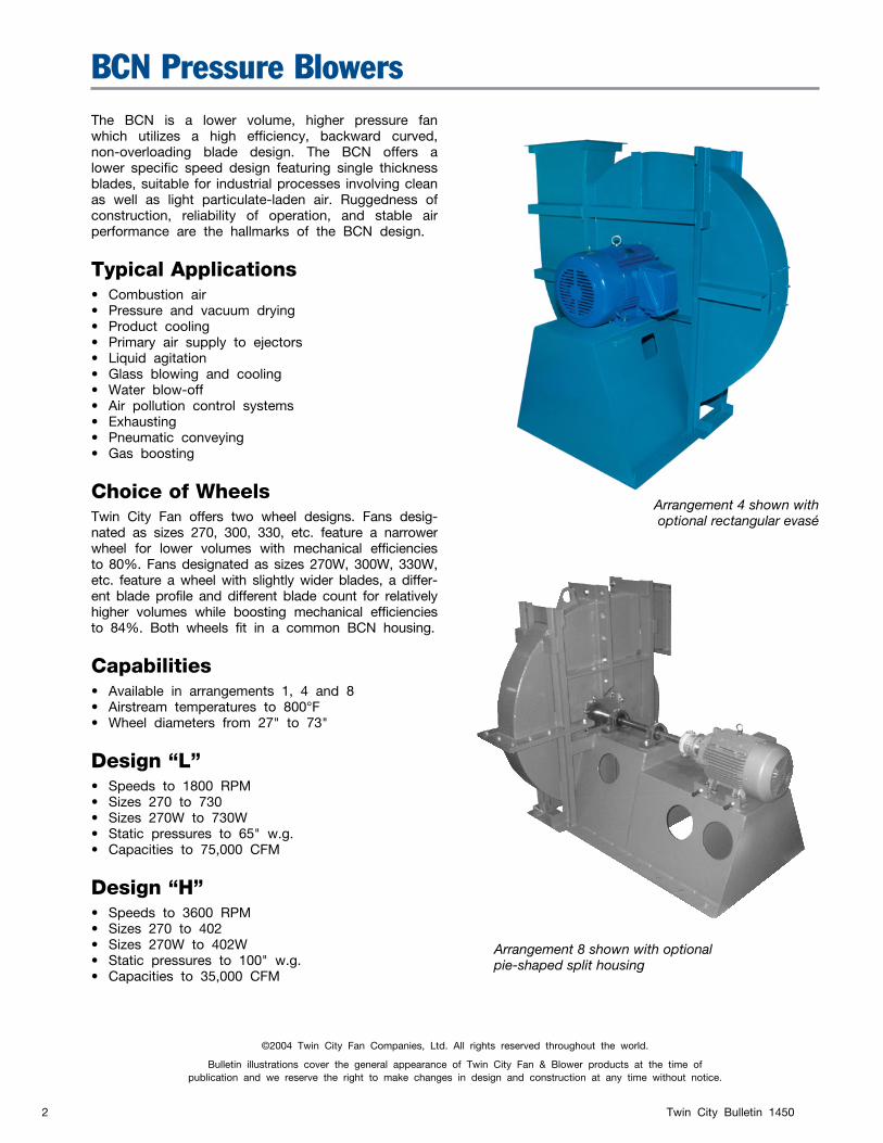
Arrangement 4 shown withoptional rectangular evasé
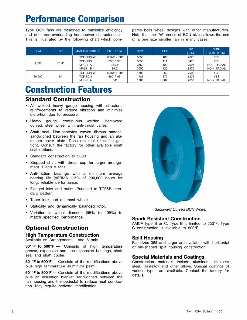
Arrangement 8 shown with optionalpie-shaped split housing
Twin City Bulletin 14503
Construction FeaturesStandard Construction• All welded heavy gauge housing with structural
reinforcements to reduce vibration and minimize distortion due to pressure.
• Heavy gauge, continuous welded, backward curved, steel wheel with anti-thrust vanes.
• Shaft seal. Non-asbestos woven fibrous material sandwiched between the fan housing and an alu-minum cover plate. Does not make the fan gas tight. Consult the factory for other available shaft seal options.
• Standard construction to 300°F
• Stepped shaft with thrust cap for larger arrange-ment 1 and 8 fans.
• Anti-friction bearings with a minimum average bearing life (AFBMA L-50) of 200,000 hours for long, reliable performance.
• Flanged inlet and outlet. Punched to TCF&B stan-dard pattern.
• Taper lock hub on most wheels.
• Statically and dynamically balanced rotor.
• Variation in wheel diameter (95% to 105%) to match specified performance.
Optional ConstructionHigh Temperature ConstructionAvailable on Arrangement 1 and 8 only.
301°F to 500°F — Consists of high temperature grease, expansion and non-expansion bearings, shaft seal and shaft cooler.
501°F to 600°F — Consists of the modifications above plus high temperature aluminum paint.
601°F to 800°F — Consists of the modifications above plus an insulation blanket sandwiched between the fan housing and the pedestal to reduce heat conduc-tion. May require pedestal modification.
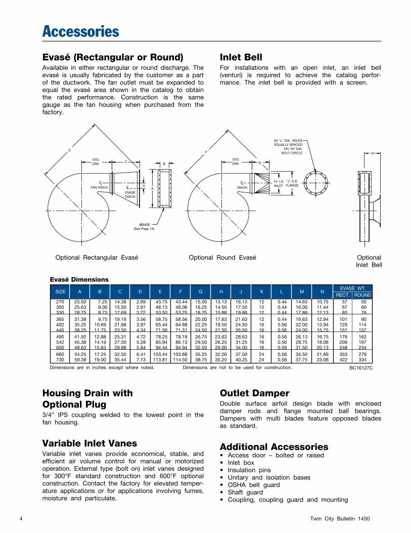
Backward Curved BCN Wheel
Spark Resistant ConstructionAMCA type B or C. Type B is limited to 250°F. Type C construction is available to 800°F.
Split HousingFan sizes 365 and larger are available with horizontal or pie-shaped split housing construction.
Special Materials and CoatingsConstruction materials include aluminum, stainless steel, Hastelloy and other alloys. Special coatings of various types are available. Contact the factory for details.
Performance ComparisonType BCN fans are designed to maximize efficiency and offer non-overloading horsepower characteristics. This is illustrated by the following chart which com-
pares both wheel designs with other manufacturers. Note that the "W" series of BCN sizes allows the use of a one size smaller fan in many cases.
CFM SP MANUFACTURER SIZE / DIA. RPM BHP
OV
NON-
(FPM)
OVERLOADING
TCF-BCN-W 300W / 30" 3550 106 7826 YES
9,000 61.4" TCF-BCN 330 / 33" 3550 111 6475 YES
MFGR. A 28.75" 3550 120 7095 NO - RADIAL MFGR. B 29.5" 3550 126 9375 NO - RADIAL
TCF-BCN-W 600W / 60" 1785 363 7609 YES 35,000 54" TCF-BCN 660 / 66" 1785 370 6272 YES MFGR. A 54" 1785 382 7630 NO - RADIAL
Twin City Bulletin 14504
Evasé (Rectangular or Round)Available in either rectangular or round discharge. The evasé is usually fabricated by the customer as a part of the ductwork. The fan outlet must be expanded to equal the evasé area shown in the catalog to obtain the rated performance. Construction is the same gauge as the fan housing when purchased from the factory.
Inlet BellFor installations with an open inlet, an inlet bell (venturi) is required to achieve the catalog perfor-mance. The inlet bell is provided with a screen.
E
STD.DIM.
C
DCL
CL
CLFAN DISCH.
EVASÉDISCH.
FLANGE(See Page 14)
A
B
DISCH.
F
STD.DIM. G
(K) "L" DIA. HOLESEQUALLY SPACED
ON "M" DIA.BOLT CIRCLE
"H" I.D.INLET
"J" O.D.FLANGE
N
Optional Rectangular Evasé Optional Round Evasé Optional Inlet Bell
SIZE A B C D E F G H J K L M N EVASÉ WT.
RECT. ROUND 270 23.50 7.25 14.38 2.69 43.75 43.44 15.00 13.13 16.13 12 0.44 14.63 10.75 57 50 300 25.63 8.00 15.50 2.91 48.13 48.06 16.25 14.50 17.50 12 0.44 16.00 11.44 67 60 330 28.75 8.75 17.69 3.22 53.50 53.25 18.25 15.88 19.88 12 0.44 17.88 12.13 85 76 365 31.38 9.75 19.19 3.56 58.75 58.56 20.00 17.63 21.63 12 0.44 19.63 12.94 101 90 402 35.25 10.69 21.88 3.97 65.44 64.88 22.25 19.50 24.50 16 0.56 22.00 13.94 129 114 445 38.25 11.75 23.50 4.34 71.56 71.31 24.50 21.50 26.50 16 0.56 24.00 15.75 151 137 490 41.50 12.88 25.31 4.72 78.25 78.19 26.75 23.63 28.63 16 0.56 26.13 16.75 176 162 542 45.38 14.19 27.50 5.28 85.94 86.13 29.50 26.25 31.25 16 0.56 28.75 18.06 209 197 600 49.63 15.63 29.88 5.84 94.44 94.94 32.50 29.00 34.00 16 0.56 31.50 20.13 248 234 660 54.25 17.25 32.50 6.41 103.44 103.88 35.25 32.00 37.00 24 0.56 34.50 21.69 353 279 730 59.38 19.00 35.44 7.13 113.81 114.50 38.75 35.25 40.25 24 0.56 37.75 23.06 422 334
Accessories
Dimensions are in inches except where noted. Dimensions are not to be used for construction.
Housing Drain withOptional Plug3/4" IPS coupling welded to the lowest point in the fan housing.
Variable Inlet VanesVariable inlet vanes provide economical, stable, and efficient air volume control for manual or motorized operation. External type (bolt on) inlet vanes designed for 300°F standard construction and 600°F optional construction. Contact the factory for elevated temper-ature applications or for applications involving fumes, moisture and particulate.
Outlet DamperDouble surface airfoil design blade with enclosed damper rods and flange mounted ball bearings. Dampers with multi blades feature opposed blades as standard.
Additional Accessories• Access door – bolted or raised• Inlet box• Insulation pins• Unitary and isolation bases• OSHA belt guard• Shaft guard• Coupling, coupling guard and mounting
BC16127C
Evasé Dimensions
Twin City Bulletin 14505
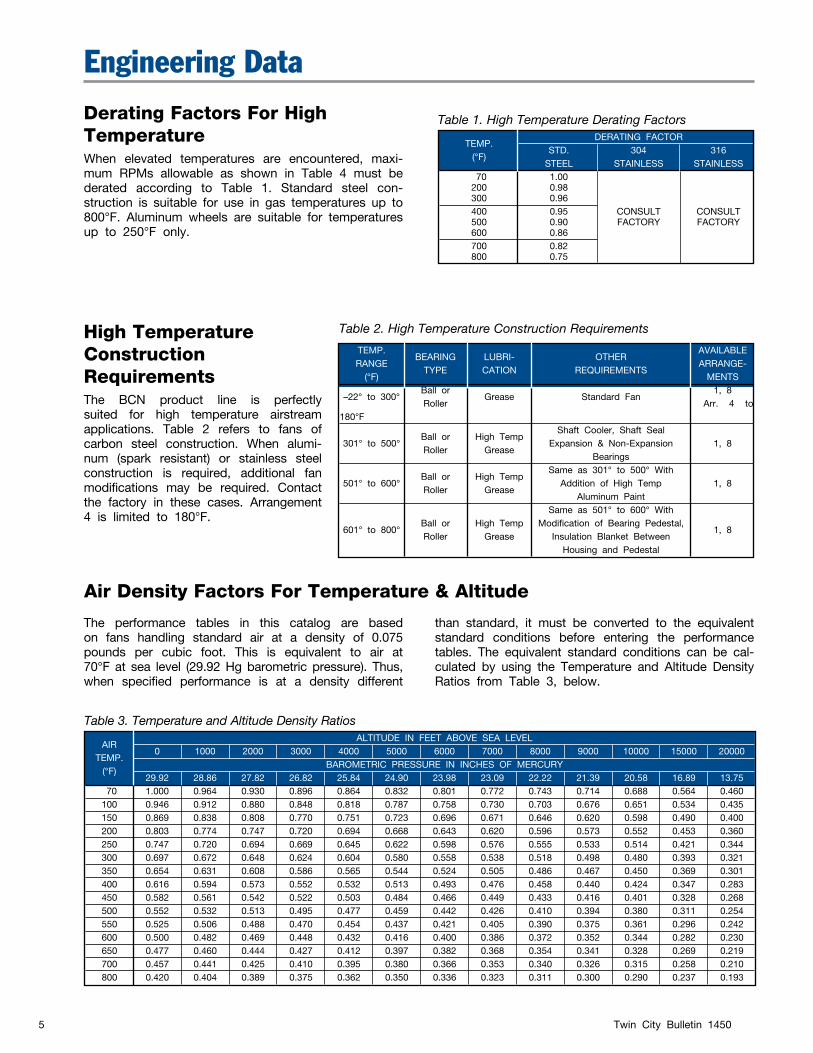
Derating Factors For High TemperatureWhen elevated temperatures are encountered, maxi-mum RPMs allowable as shown in Table 4 must be derated according to Table 1. Standard steel con-struction is suitable for use in gas temperatures up to 800°F. Aluminum wheels are suitable for temperatures up to 250°F only.
High TemperatureConstruction RequirementsThe BCN product line is perfectly suited for high temperature airstream applications. Table 2 refers to fans of carbon steel construction. When alumi-num (spark resistant) or stainless steel construction is required, additional fan modifications may be required. Contact the factory in these cases. Arrangement 4 is limited to 180°F.
Table 1. High Temperature Derating Factors
Engineering Data
TEMP.
DERATING FACTOR
(°F) STD. 304 316
STEEL STAINLESS STAINLESS 70 1.00 200 0.98 300 0.96 400 0.95 CONSULT CONSULT 500 0.90 FACTORY FACTORY 600 0.86 700 0.82 800 0.75
Table 2. High Temperature Construction Requirements
TEMP. BEARING
OTHER
AVAILABLE RANGE
TYPE
LUBRI-
REQUIREMENTS ARRANGE-
(°F) CATION
MENTS –22° to 300°
Ball or Grease Standard Fan
1, 8 Roller Arr. 4 to 180°F Shaft Cooler, Shaft Seal 301° to 500°
Ball or High Temp Expansion & Non-Expansion 1, 8
Roller Grease
Bearings Same as 301° to 500° With 501° to 600°
Ball or High Temp Addition of High Temp 1, 8
Roller Grease
Aluminum Paint Same as 501° to 600° With 601° to 800°
Ball or
High Temp Modification of Bearing Pedestal, 1, 8
Roller
Grease Insulation Blanket Between Housing and Pedestal
AIR
ALTITUDE IN FEET ABOVE SEA LEVEL
TEMP. 0 1000 2000 3000 4000 5000 6000 7000 8000 9000 10000 15000 20000
(°F)
BAROMETRIC PRESSURE IN INCHES OF MERCURY 29.92 28.86 27.82 26.82 25.84 24.90 23.98 23.09 22.22 21.39 20.58 16.89 13.75 70 1.000 0.964 0.930 0.896 0.864 0.832 0.801 0.772 0.743 0.714 0.688 0.564 0.460 100 0.946 0.912 0.880 0.848 0.818 0.787 0.758 0.730 0.703 0.676 0.651 0.534 0.435 150 0.869 0.838 0.808 0.770 0.751 0.723 0.696 0.671 0.646 0.620 0.598 0.490 0.400 200 0.803 0.774 0.747 0.720 0.694 0.668 0.643 0.620 0.596 0.573 0.552 0.453 0.360 250 0.747 0.720 0.694 0.669 0.645 0.622 0.598 0.576 0.555 0.533 0.514 0.421 0.344 300 0.697 0.672 0.648 0.624 0.604 0.580 0.558 0.538 0.518 0.498 0.480 0.393 0.321 350 0.654 0.631 0.608 0.586 0.565 0.544 0.524 0.505 0.486 0.467 0.450 0.369 0.301 400 0.616 0.594 0.573 0.552 0.532 0.513 0.493 0.476 0.458 0.440 0.424 0.347 0.283 450 0.582 0.561 0.542 0.522 0.503 0.484 0.466 0.449 0.433 0.416 0.401 0.328 0.268 500 0.552 0.532 0.513 0.495 0.477 0.459 0.442 0.426 0.410 0.394 0.380 0.311 0.254 550 0.525 0.506 0.488 0.470 0.454 0.437 0.421 0.405 0.390 0.375 0.361 0.296 0.242 600 0.500 0.482 0.469 0.448 0.432 0.416 0.400 0.386 0.372 0.352 0.344 0.282 0.230 650 0.477 0.460 0.444 0.427 0.412 0.397 0.382 0.368 0.354 0.341 0.328 0.269 0.219 700 0.457 0.441 0.425 0.410 0.395 0.380 0.366 0.353 0.340 0.326 0.315 0.258 0.210 800 0.420 0.404 0.389 0.375 0.362 0.350 0.336 0.323 0.311 0.300 0.290 0.237 0.193
The performance tables in this catalog are based on fans handling standard air at a density of 0.075 pounds per cubic foot. This is equivalent to air at 70°F at sea level (29.92 Hg barometric pressure). Thus, when specified performance is at a density different
than standard, it must be converted to the equivalent standard conditions before entering the performance tables. The equivalent standard conditions can be cal-culated by using the Temperature and Altitude Density Ratios from Table 3, below.
Table 3. Temperature and Altitude Density Ratios
Air Density Factors For Temperature & Altitude
Twin City Bulletin 14506
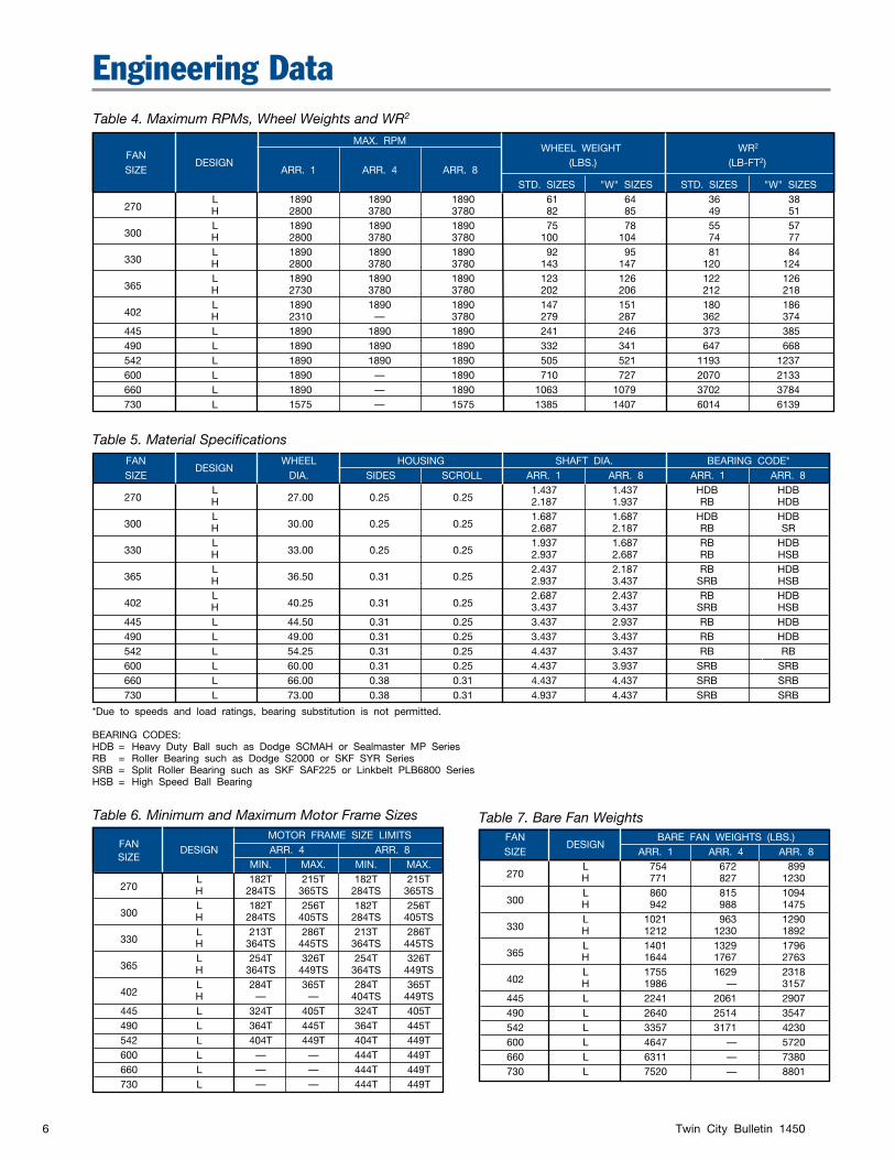
MAX. RPM WHEEL WEIGHT
WR2
FAN DESIGN
(LBS.)
(LB-FT2)
SIZE ARR. 1 ARR. 4 ARR. 8 STD. SIZES "W" SIZES STD. SIZES "W" SIZES
270 L 1890 1890 1890 61 64 36 38
H 2800 3780 3780 82 85 49 51
300 L 1890 1890 1890 75 78 55 57
H 2800 3780 3780 100 104 74 77
330 L 1890 1890 1890 92 95 81 84
H 2800 3780 3780 143 147 120 124
365 L 1890 1890 1890 123 126 122 126
H 2730 3780 3780 202 206 212 218
402 L 1890 1890 1890 147 151 180 186
H 2310 — 3780 279 287 362 374 445 L 1890 1890 1890 241 246 373 385 490 L 1890 1890 1890 332 341 647 668 542 L 1890 1890 1890 505 521 1193 1237 600 L 1890 — 1890 710 727 2070 2133 660 L 1890 — 1890 1063 1079 3702 3784 730 L 1575 — 1575 1385 1407 6014 6139
Engineering Data
*Due to speeds and load ratings, bearing substitution is not permitted.
BEARING CODES:HDB = Heavy Duty Ball such as Dodge SCMAH or Sealmaster MP SeriesRB = Roller Bearing such as Dodge S2000 or SKF SYR SeriesSRB = Split Roller Bearing such as SKF SAF225 or Linkbelt PLB6800 SeriesHSB = High Speed Ball Bearing
Table 4. Maximum RPMs, Wheel Weights and WR2
Table 5. Material Specifications
Table 6. Minimum and Maximum Motor Frame Sizes
FAN MOTOR FRAME SIZE LIMITS
SIZE
DESIGN ARR. 4 ARR. 8 MIN. MAX. MIN. MAX.
270 L 182T 215T 182T 215T
H 284TS 365TS 284TS 365TS
300 L 182T 256T 182T 256T
H 284TS 405TS 284TS 405TS
330 L 213T 286T 213T 286T
H 364TS 445TS 364TS 445TS
365 L 254T 326T 254T 326T
H 364TS 449TS 364TS 449TS
402 L 284T 365T 284T 365T
H — — 404TS 449TS 445 L 324T 405T 324T 405T 490 L 364T 445T 364T 445T 542 L 404T 449T 404T 449T 600 L — — 444T 449T 660 L — — 444T 449T 730 L — — 444T 449T
Table 7. Bare Fan Weights FAN BARE FAN WEIGHTS (LBS.) SIZE
DESIGN ARR. 1 ARR. 4 ARR. 8
270
L 754 672 899 H 771 827 1230
300 L 860 815 1094
H 942 988 1475
330 L 1021 963 1290
H 1212 1230 1892
365 L 1401 1329 1796
H 1644 1767 2763
402 L 1755 1629 2318
H 1986 — 3157 445 L 2241 2061 2907 490 L 2640 2514 3547 542 L 3357 3171 4230 600 L 4647 — 5720 660 L 6311 — 7380 730 L 7520 — 8801
FAN DESIGN
WHEEL HOUSING SHAFT DIA. BEARING CODE* SIZE DIA. SIDES SCROLL ARR. 1 ARR. 8 ARR. 1 ARR. 8
270 L
27.00 0.25 0.25 1.437 1.437 HDB HDB
H 2.187 1.937 RB HDB
300 L
30.00 0.25 0.25 1.687 1.687 HDB HDB
H 2.687 2.187 RB SR
330 L
33.00 0.25 0.25 1.937 1.687 RB HDB
H 2.937 2.687 RB HSB
365 L
36.50 0.31 0.25 2.437 2.187 RB HDB
H 2.937 3.437 SRB HSB
402 L
40.25 0.31 0.25 2.687 2.437 RB HDB
H 3.437 3.437 SRB HSB 445 L 44.50 0.31 0.25 3.437 2.937 RB HDB 490 L 49.00 0.31 0.25 3.437 3.437 RB HDB 542 L 54.25 0.31 0.25 4.437 3.437 RB RB 600 L 60.00 0.31 0.25 4.437 3.937 SRB SRB 660 L 66.00 0.38 0.31 4.437 4.437 SRB SRB 730 L 73.00 0.38 0.31 4.937 4.437 SRB SRB
Twin City Bulletin 14507
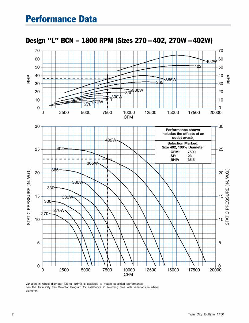
Performance Data
Design “L” BCN – 1800 RPM (Sizes 270 – 402, 270W – 402W)70
60
50
40
30
20
10
70
60
50
40
30
20
10
30
25
20
15
10
5
30
25
20
15
10
5
0
0 0
BH
PS
TATI
C P
RE
SS
UR
E (I
N. W
.G.)
0
STA
TIC
PR
ES
SU
RE
(IN
. W.G
.)B
HP
0 2500 5000 7500 10000 12500 15000 17500 20000CFM
0 2500 5000 7500 10000 12500 15000 17500 20000CFM
402W
402W
365W
365W
330W
330W
300W
300W
270W
270W
402
402
365
365
330
330
300
300
270
270
Performance shownincludes the effects of an
outlet evasé.Selection Marked:
Size 402, 100% DiameterCFM: 7500SP: 23BHP: 35.5
Variation in wheel diameter (95 to 105%) is available to match specified performance.See the Twin City Fan Selector Program for assistance in selecting fans with variations in wheel diameter.
Twin City Bulletin 14508
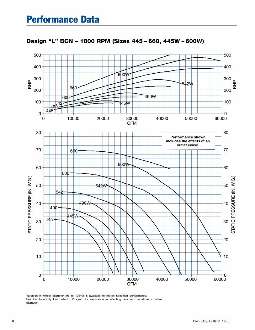
Performance Data
Design “L” BCN – 1800 RPM (Sizes 445 – 660, 445W – 600W)
500
400
300
200
100
80
70
60
50
40
30
20
10
80
70
60
50
40
30
20
10
0
0
500
400
300
200
100
0
BH
PS
TATI
C P
RE
SS
UR
E (I
N. W
.G.)
0
STA
TIC
PR
ES
SU
RE
(IN
. W.G
.)B
HP
0 10000 20000 30000 40000 50000 60000CFM
0 10000 20000 30000 40000 50000 60000CFM
600W
660
542W
600W
490W
542W
445W
490W
445W
660
600
600
542
542
490
490
445
445
Performance shownincludes the effects of an
outlet evasé.
Variation in wheel diameter (95 to 105%) is available to match specified performance.See the Twin City Fan Selector Program for assistance in selecting fans with variations in wheel diameter.
Twin City Bulletin 14509
Performance Data
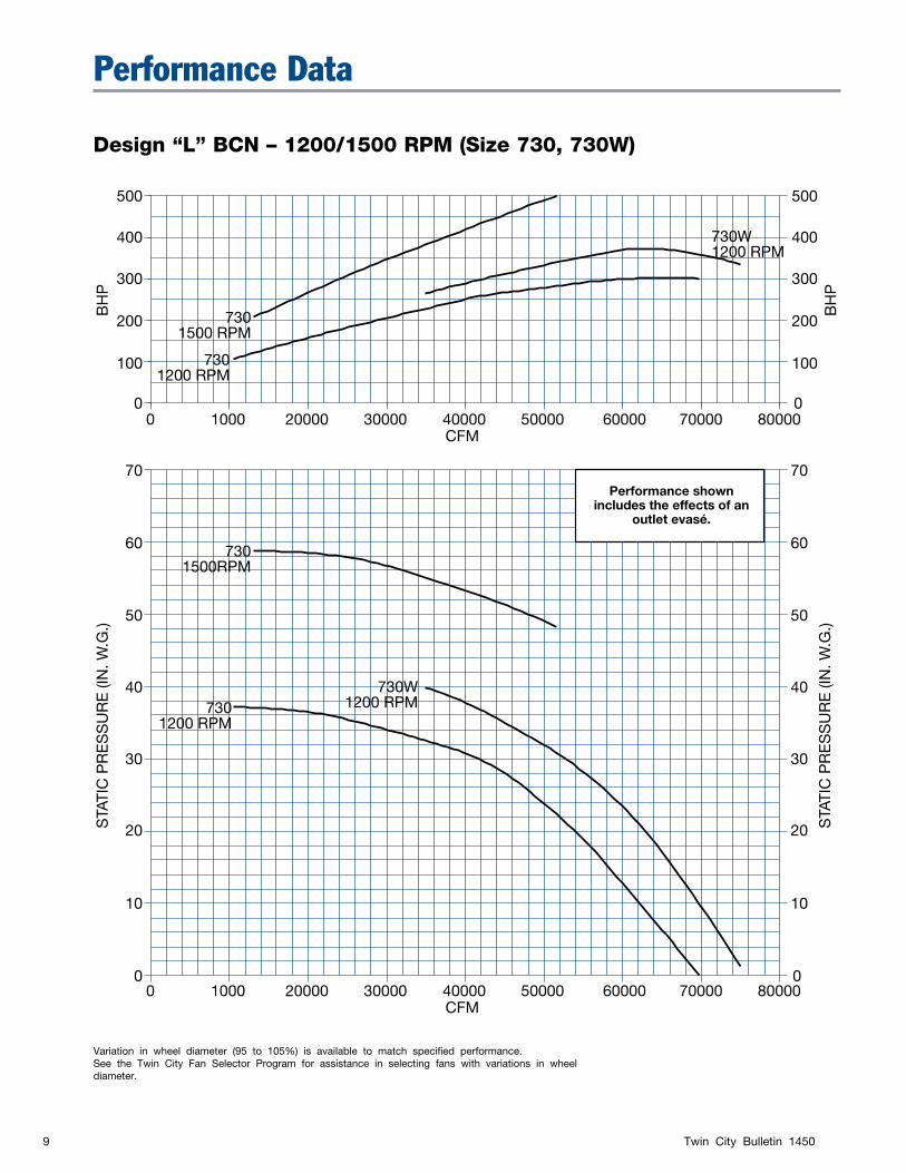
Design “L” BCN – 1200/1500 RPM (Size 730, 730W)
500
400
300
200
100
500
400
300
200
100
70
60
50
40
30
20
10
70
60
50
40
30
20
10
0
0 0
BH
PS
TATI
C P
RE
SS
UR
E (I
N. W
.G.)
0
STA
TIC
PR
ES
SU
RE
(IN
. W.G
.)B
HP
0 1000 20000 30000 40000 50000 60000 70000 80000CFM
0 1000 20000 30000 40000 50000 60000 70000 80000CFM
730W1200 RPM
7301500 RPM
7301200 RPM
7301200 RPM
7301500RPM
730W1200 RPM
Performance shownincludes the effects of an
outlet evasé.
Variation in wheel diameter (95 to 105%) is available to match specified performance.See the Twin City Fan Selector Program for assistance in selecting fans with variations in wheel diameter.
Twin City Bulletin 145010
Performance Data
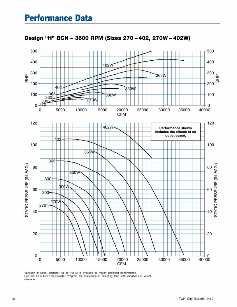
Design “H” BCN – 3600 RPM (Sizes 270 – 402, 270W – 402W)
500
400
300
200
100
120
100
80
60
40
20
0
0
500
400
300
200
100
0
BH
PS
TATI
C P
RE
SS
UR
E (I
N. W
.G.)
120
100
80
60
40
20
0
STA
TIC
PR
ES
SU
RE
(IN
. W.G
.)B
HP
0 5000 10000 15000 20000 25000 30000 35000 40000CFM
0 5000 10000 15000 20000 25000 30000 35000 40000CFM
402W
402W
365W
365W
330W
330W
300W
300W
270W
270W
402
402
365
365
330
330
300
300
270
270
Performance shownincludes the effects of an
outlet evasé.
Variation in wheel diameter (95 to 105%) is available to match specified performance.See the Twin City Fan Selector Program for assistance in selecting fans with variations in wheel diameter.
Twin City Bulletin 145011
FAN
SH
AFT
C L
CL
8 BH
HOLESDIA. BASE
FAN HSG
CC
C O.D.FLANGEI.D.
FLANGE
DISCHL
C
KL
SE
SD
BABASE ANGLES
KSKWY. SIZE
OUTSIDEHOUSING
B ADISCH.
FLANGE
DX
GBGA. SCROLL
NOTE 1
KA
KB
L
L
DIA. SHAFT
GA. SIDESGA
HQ
HE HA
HC
Q
DC
P
GCG
HN
JA
M M
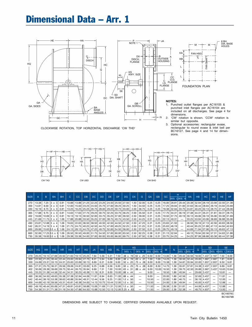
Dimensional Data – Arr. 1
DIMENSIONS ARE SUBJECT TO CHANGE. CERTIFIED DRAWINGS AVAILABLE UPON REQUEST.
SIZE A B BA BH C CC DB DC DD DE DF DG DX G GA GB GC H HA HB HC HD HE HF
DES. L DES. H
270 13.38 7.25 3 x 3 0.81 10.88 13.88 21.25 22.25 23.25 24.50 25.50 27.50 1.50 32.00 0.25 0.25 16.00 28.81 29.44 20.38 32.94 26.19 23.56 22.50 21.38 300 14.81 8.00 3 x 3 0.81 12.00 15.00 23.25 24.50 25.75 27.00 28.25 30.25 1.50 34.50 0.25 0.25 17.25 29.94 31.00 22.63 36.44 28.94 26.19 24.94 23.69 330 16.19 8.75 3 x 3 0.81 13.25 16.25 25.25 26.75 28.00 29.25 30.75 33.00 2.00 36.75 0.25 0.25 18.38 32.94 33.75 24.81 40.25 32.13 28.75 27.44 26.06
365 17.88 9.75 3 x 3 0.81 14.63 17.63 27.75 29.25 30.75 32.25 33.75 36.25 2.00 35.50 0.31 0.25 17.75 34.31 36.19 27.38 44.31 35.31 31.81 30.31 28.75 402 19.69 10.69 3 x 3 0.81 16.13 19.13 30.50 32.00 33.75 35.25 37.00 39.50 2.50 39.00 0.31 0.25 19.50 37.75 40.19 30.13 49.06 39.19 35.06 33.38 31.69 445 21.69 11.75 3 x 4 1.06 17.88 20.88 33.50 35.25 37.00 38.75 40.75 43.50 2.50 44.25 0.31 0.25 22.13 40.31 — 33.25 53.94 43.06 38.69 36.88 35.06
490 23.81 12.88 3 x 4 1.06 19.63 22.63 36.50 38.50 40.50 42.50 44.50 47.50 2.50 47.25 0.31 0.25 23.63 41.50 — 36.56 59.19 47.13 42.56 40.63 38.56 542 26.31 14.19 3 x 4 1.06 21.75 24.75 40.25 42.50 44.75 47.00 49.25 52.25 2.50 51.25 0.31 0.25 25.63 46.19 — 40.44 65.25 51.88 47.13 44.94 42.63 600 29.06 15.63 3.5 x 5 1.06 24.13 28.13 44.75 47.25 49.75 52.00 54.50 58.00 2.50 57.50 0.31 0.25 28.75 49.19 — 44.69 71.94 57.06 52.13 49.63 47.13
660 32.06 17.25 3.5 x 5 1.06 26.50 30.50 49.00 51.75 54.50 57.00 60.00 63.50 2.50 62.25 0.38 0.31 31.13 52.94 — 49.13 78.94 62.56 57.31 54.63 51.88 730 35.38 19.00 3.5 x 5 1.06 29.38 33.38 54.00 57.00 60.00 63.00 66.00 69.75 2.50 67.50 0.38 0.31 33.75 54.25 — 54.25 87.06 68.88 63.38 60.44 57.38
SIZE HG HH HQ HR HS HT HU JA KA KB KL KS
L M N
P Q
SD SE
DES. L DES. H DES. L DES. H DES. L DES. H DES. L DES. H DES. L DES.H
H270 20.25 19.13 27.69 20.50 21.63 19.13 25.25 7.94 5.56 5.31 7.50 .38 x .19 .50 x .25 6.50 6.50 13.00 1.38 29.44 30.56 18.00 1.437 2.187 7.50 8.00 300 22.50 21.25 30.44 22.44 23.63 20.94 27.75 8.31 5.94 5.69 8.00 .38 x .19 .63 x .31 7.00 7.00 14.25 1.38 30.50 32.44 20.00 1.687 2.687 7.81 8.69 330 24.69 23.31 33.13 24.31 25.63 22.69 30.13 8.69 6.31 6.06 9.00 .50 x .25 .75 x .38 8.00 8.00 15.38 1.38 34.81 35.94 22.00 1.937 2.937 9.50 9.81
365 27.31 25.75 36.31 26.56 28.06 24.81 33.00 9.25 6.88 6.56 9.00 .50 x .25 .75 x .38 8.00 8.50 14.75 1.38 35.81 37.81 24.38 2.437 2.937 9.69 9.81 402 30.06 28.38 39.69 28.75 30.44 26.75 35.94 9.69 7.31 7.00 10.00 .63 x .31 .88 x .44 9.00 10.00 16.50 1.38 39.75 42.50 26.88 2.687 3.437 10.63 10.94 445 33.25 31.38 44.56 32.44 34.31 30.25 40.38 11.19 8.31 8.00 10.00 .88 x .44 — 9.00 — 18.50 1.88 40.94 — 29.69 3.437 — 10.81 —
490 36.56 34.50 48.63 35.38 37.38 32.94 44.06 11.81 8.94 8.63 11.00 .88 x .44 — 9.00 — 20.00 1.88 42.56 — 32.69 3.437 — 11.81 — 542 40.44 38.19 53.38 38.63 40.88 35.94 48.31 12.44 9.56 9.25 11.00 1.0 x .50 — 10.50 — 22.00 1.88 46.75 — 36.19 4.437 — 12.00 — 600 44.69 42.19 59.56 43.31 45.81 40.38 54.00 14.13 10.75 10.44 12.00 1.0 x .50 — 10.50 — 24.00 2.38 49.94 — 40.00 4.437 — 12.88 —
660 49.19 46.44 65.06 47.31 49.81 43.81 58.88 15.06 11.69 11.31 12.00 1.0 x .50 — 11.50 — 26.38 2.38 51.81 — 44.06 4.437 — 12.88 — 730 54.38 51.31 71.38 51.19 54.50 47.88 64.50 15.88 12.50 12.13 12.00 1.25 x .63 — 11.50 — 29.00 2.38 52.38 — 48.75 4.937 — 13.00 —
BC16076CBC16079B
NOTES:1. Punched outlet flanges per AC16105 &
punched inlet flanges per AC16104 are included on all discharges. See page 4 for dimensions.
2. 'CW' rotation is shown. 'CCW' rotation is similar but opposite.
3. Optional accessories: rectangular evase, rectangular to round evase & inlet bell per BC16127. See page 4 and 14 for dimen-sions.
CW TAU
HD HH
HB
DD
CW UBD
HC HG
HA HT
DE
CW BHD
HA HE
HG HS
DG*
CW BAU
HB HF
DF
HH HR
CW TAD
DB
HU
HF HB
HD
CLOCKWISE ROTATION, TOP HORIZONTAL DISCHARGE 'CW THD'
FOUNDATION PLAN
Twin City Bulletin 145012
FAN
SH
AFT
C L
CL
8 BH
HOLESDIA. BASE
FAN HSG
CC
CO.D.
FLANGEI.D.FLANGE
DISCHL
C
BABASE ANGLES
OUTSIDEHOUSING
B ADISCH.
FLANGE
DX
GBGA. SCROLL
NOTE 1 KA
KB
L
L
GA. SIDESGA
HQ
HE HA
HC
Q
DC
P(MAX.)
GC
G HN
JAM M
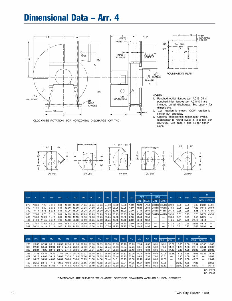
Dimensional Data – Arr. 4
DIMENSIONS ARE SUBJECT TO CHANGE. CERTIFIED DRAWINGS AVAILABLE UPON REQUEST.
BC16077ABC16080A
SIZE A B BA BH C CC DB DC DD DE DF DG DX
FR
G
GA GB GC H
DES. L DES. H
DES. L DES.H MIN. MAX. MIN. MAX.
270 13.38 7.25 3 x 3 0.81 10.88 13.88 21.25 22.25 23.25 24.50 25.50 27.50 1.50 182T 215T 284TS 365TS 32.00 0.25 0.25 16.00 24.81 34.81 300 14.81 8.00 3 x 3 0.81 12.00 15.00 23.25 24.50 25.75 27.00 28.25 30.25 1.50 182T 256T 284TS 405TS 34.50 0.25 0.25 17.25 30.19 38.69 330 16.19 8.75 3 x 3 0.81 13.25 16.25 25.25 26.75 28.00 29.25 30.75 33.00 2.00 213T 286T 364TS 445TS 36.75 0.25 0.25 18.38 33.19 43.94
365 17.88 9.75 3 x 3 0.81 14.63 17.63 27.75 29.25 30.75 32.25 33.75 36.25 2.00 254T 326T 364TS 449TS 35.50 0.31 0.25 17.75 36.75 49.50 402 19.69 10.69 3 x 3 0.81 16.13 19.13 30.50 32.00 33.75 35.25 37.00 39.50 2.50 284T 365T — — 39.00 0.31 0.25 19.50 38.25 — 445 21.69 11.75 3 x 4 1.06 17.88 20.88 33.50 35.25 37.00 38.75 40.75 43.50 2.50 324T 405T — — 44.25 0.31 0.25 22.13 43.44 —
490 23.81 12.88 3 x 4 1.06 19.63 22.63 36.50 38.50 40.50 42.50 44.50 47.50 2.50 364T 445T — — 47.25 0.31 0.25 23.63 49.13 — 542 26.31 14.19 3 x 4 1.06 21.75 24.75 40.25 42.50 44.75 47.00 49.25 52.25 2.50 404T 449T — — 51.25 0.31 0.25 25.63 54.94 —
SIZE HA HB HC HD HE HF HG HH HQ HR HS HT HU JA KA KB L M N
P Q
DES. L DES. H DES. L DES. H
270 20.38 32.94 26.19 23.56 22.50 21.38 20.25 19.13 27.69 20.50 21.63 19.13 25.25 7.94 5.56 5.31 5.31 10.31 13.00 1.38 20.94 32.56 18.00 300 22.63 36.44 28.94 26.19 24.94 23.69 22.50 21.25 30.44 22.44 23.63 20.94 27.75 8.31 5.94 5.69 7.63 11.88 14.25 1.38 26.19 38.44 20.00 330 24.81 40.25 32.13 28.75 27.44 26.06 24.69 23.31 33.13 24.31 25.63 22.69 30.13 8.69 6.31 6.06 8.75 14.13 15.38 1.38 29.06 45.31 22.00
365 27.38 44.31 35.31 31.81 30.31 28.75 27.31 25.75 36.31 26.56 28.06 24.81 33.00 9.25 6.88 6.56 10.00 16.38 14.75 1.38 32.06 50.31 24.38 402 30.13 49.06 39.19 35.06 33.38 31.69 30.06 28.38 39.69 28.75 30.44 26.75 35.94 9.69 7.31 7.00 10.31 — 16.50 1.38 34.25 — 26.88 445 33.25 53.94 43.06 38.69 36.88 35.06 33.25 31.38 44.56 32.44 34.31 30.25 40.38 11.19 8.31 8.00 11.63 — 18.50 1.88 40.25 — 29.69
490 36.56 59.19 47.13 42.56 40.63 38.56 36.56 34.50 48.63 35.38 37.38 32.94 44.06 11.81 8.94 8.63 13.88 — 20.00 1.88 47.38 — 32.69 542 40.44 65.25 51.88 47.13 44.94 42.63 40.44 38.19 53.38 38.63 40.88 35.94 48.31 12.44 9.56 9.25 16.13 — 22.00 1.88 52.50 — 36.19
NOTES:1. Punched outlet flanges per AC16105 &
punched inlet flanges per AC16104 are included on all discharges. See page 4 for dimensions.
2. 'CW' rotation is shown. 'CCW' rotation is similar but opposite.
3. Optional accessories: rectangular evase, rectangular to round evase & inlet bell per BC16127. See page 4 and 14 for dimen-sions.
CW TAU
HD HH
HB
DD
CW UBD
HC HG
HA HT
DE
CW BHD
HA HE
HG HS
DG*
CW BAU
HB HF
DF
HH HR
CW TAD
DB
HU
HF HB
HD
CLOCKWISE ROTATION, TOP HORIZONTAL DISCHARGE 'CW THD'
FOUNDATION PLAN

Twin City Bulletin 145013
FAN
SH
AFT
C L
CL
18 BH
HOLESDIA. BASE
FAN HSG
CC
C O.D.FLANGEI.D.
FLANGE
DISCHL
C
KL
SE
SDDIA.
SHAFT
BABASE ANGLES
KSKWY. SIZE
OUTSIDEHOUSING
B ADISCH.
FLANGE
DX
GBGA. SCROLL
NOTE 1 0.50
SHAFT GAP
NOTE 4
KA
KB
7 SP. @ L
GA. SIDESGA
HQ
HE HA
HC
Q
DC
PML(MAX.)
GCG H
N
JAM M
Dimensional Data – Arr. 8
DIMENSIONS ARE SUBJECT TO CHANGE. CERTIFIED DRAWINGS AVAILABLE UPON REQUEST.
BC16078CBC16081B
SIZE A B BA BH C CC DB DC
270 13.38 7.25 3 x 3 0.81 10.88 13.88 21.25 22.25 300 14.81 8.00 3 x 3 0.81 12.00 15.00 23.25 24.50 330 16.19 8.75 3 x 3 0.81 13.25 16.25 25.25 26.75
365 17.88 9.75 3 x 3 0.81 14.63 17.63 27.75 29.25 402 19.69 10.69 3 x 3 0.81 16.13 19.13 30.50 32.00 445 21.69 11.75 3 x 4 1.06 17.88 20.88 33.50 35.25
490 23.81 12.88 3 x 4 1.06 19.63 22.63 36.50 38.50 542 26.31 14.19 3 x 4 1.06 21.75 24.75 40.25 42.50 600 29.06 15.63 3.5 x 5 1.06 24.13 28.13 44.75 47.25
660 32.06 17.25 3.5 x 5 1.06 26.50 30.50 49.00 51.75 730 35.38 19.00 3.5 x 5 1.06 29.38 33.38 54.00 57.00
SIZE DD DE DF DG DX FR
G GA GB GC H HA HB HC HD HE HF HG HH HQ HR
DES. L DES. H DES. L DES. H
270 23.25 24.50 25.50 27.50 1.50 215T 365TS 32.00 0.25 0.25 16.00 53.81 65.19 20.38 32.94 26.19 23.56 22.50 21.38 20.25 19.13 27.69 20.50 300 25.75 27.00 28.25 30.25 1.50 256T 405TS 34.50 0.25 0.25 17.25 60.50 70.19 22.63 36.44 28.94 26.19 24.94 23.69 22.50 21.25 30.44 22.44 330 28.00 29.25 30.75 33.00 2.00 286T 445TS 36.75 0.25 0.25 18.38 67.13 79.63 24.81 40.25 32.13 28.75 27.44 26.06 24.69 23.31 33.13 24.31
365 30.75 32.25 33.75 36.25 2.00 326T 449TS 35.50 0.31 0.25 17.75 72.50 87.06 27.38 44.31 35.31 31.81 30.31 28.75 27.31 25.75 36.31 26.56 402 33.75 35.25 37.00 39.50 2.50 365T 449TS 39.00 0.31 0.25 19.50 78.25 90.94 30.13 49.06 39.19 35.06 33.38 31.69 30.06 28.38 39.69 28.75 445 37.00 38.75 40.75 43.50 2.50 405T — 44.25 0.31 0.25 22.13 85.31 — 33.25 53.94 43.06 38.69 36.88 35.06 33.25 31.38 44.56 32.44
490 40.50 42.50 44.50 47.50 2.50 445T — 47.25 0.31 0.25 23.63 94.00 — 36.56 59.19 47.13 42.56 40.63 38.56 36.56 34.50 48.63 35.38 542 44.75 47.00 49.25 52.25 2.50 449T — 51.25 0.31 0.25 25.63 95.88 — 40.44 65.25 51.88 47.13 44.94 42.63 40.44 38.19 53.38 38.63 600 49.75 52.00 54.50 58.00 2.50 449T — 57.50 0.31 0.25 28.75 103.06 — 44.69 71.94 57.06 52.13 49.63 47.13 44.69 42.19 59.56 43.31
660 54.50 57.00 60.00 63.50 2.50 449T — 62.25 0.38 0.31 31.13 106.81 — 49.13 78.94 62.56 57.31 54.63 51.88 49.19 46.44 65.06 47.31 730 60.00 63.00 66.00 69.75 2.50 449T — 67.50 0.38 0.31 33.75 108.50 — 54.25 87.06 68.88 63.38 60.44 57.38 54.38 51.31 71.38 51.19
SIZE HS HT HU JA KA KB KL KS
L M
ML N
P Q
SD SE
DES. L DES. H DES. L DES. H DES. L DES. H DES. L DES. H DES. L DES. H DES. L DES.H
270 21.63 19.13 25.25 7.94 5.56 5.31 7.50 .38 x .19 .50 x .25 5.50 7.00 13.00 20.25 32.25 1.38 29.44 30.44 18.00 1.437 1.937 7.50 7.75 300 23.63 20.94 27.75 8.31 5.94 5.69 8.00 .38 x .19 .50 x .25 6.50 7.50 14.25 25.75 38.25 1.38 30.50 31.44 20.00 1.687 2.187 7.81 8.38 330 25.63 22.69 30.13 8.69 6.31 6.06 9.00 .38 x .19 .63 x .31 7.00 9.00 15.38 28.88 45.25 1.38 33.88 35.50 22.00 1.687 2.687 8.81 10.19
365 28.06 24.81 33.00 9.25 6.88 6.56 9.00 .50 x .25 .88 x .44 7.50 10.00 14.75 32.00 49.75 1.38 35.56 37.88 24.38 2.187 3.437 9.44 9.75 402 30.44 26.75 35.94 9.69 7.31 7.00 10.00 .63 x .31 .88 x .44 8.50 10.00 16.50 34.38 49.75 1.38 39.63 41.31 26.88 2.437 3.437 10.63 10.75 445 34.31 30.25 40.38 11.19 8.31 8.00 10.00 .75 x .38 — 9.00 — 18.50 41.25 — 1.88 40.63 — 29.69 2.937 — 10.75 —
490 37.38 32.94 44.06 11.81 8.94 8.63 11.00 .88 x .44 — 10.00 — 20.00 49.00 — 1.88 43.00 — 32.69 3.437 — 11.88 — 542 40.88 35.94 48.31 12.44 9.56 9.25 11.00 .88 x .44 — 10.00 — 22.00 49.00 — 1.88 44.19 — 36.19 3.437 — 11.81 — 600 45.81 40.38 54.00 14.13 10.75 10.44 12.00 1.0 x .50 — 11.00 — 24.00 49.00 — 2.38 49.69 — 40.00 3.937 — 12.88 —
660 49.81 43.81 58.88 15.06 11.69 11.31 12.00 1.0 x .50 — 11.00 — 26.38 49.00 — 2.38 52.56 — 44.06 4.437 — 12.88 — 730 54.50 47.88 64.50 15.88 12.50 12.13 12.00 1.0 x .50 — 11.00 — 29.00 49.00 — 2.38 53.38 — 48.75 4.437 — 12.88 —
NOTES:1. Punched outlet flanges per AC16105 &
punched inlet flanges per AC16104 are included on all discharges. See page 4 for dimensions.
2. 'CW' rotation is shown. 'CCW' rotation is similar but opposite.
3. Optional accessories: rectangular evase, rectangular to round evase & inlet bell per BC16127. See page 4 and 14 for dimen-sions.
CW TAU
HD HH
HB
DD
CW UBD
HC HG
HA HT
DE
CW BHD
HA HE
HG HS
DG*
CW BAU
HB HF
DF
HH HR
CW TAD
DB
HU
HF HB
HD
FOUNDATION PLAN
CLOCKWISE ROTATION, TOP HORIZONTAL DISCHARGE 'CW THD'
Twin City Bulletin 145014
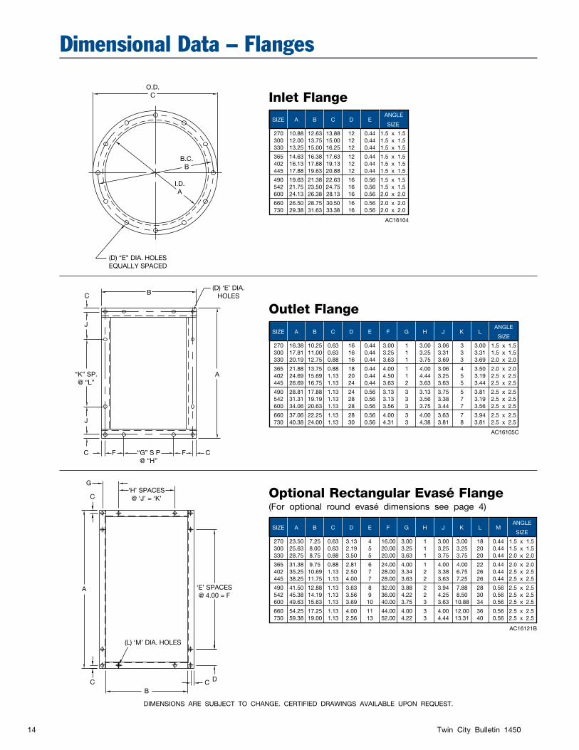
Dimensional Data – Flanges
DIMENSIONS ARE SUBJECT TO CHANGE. CERTIFIED DRAWINGS AVAILABLE UPON REQUEST.
SIZE A B C D E F G H J K L M ANGLE
SIZE
270 23.50 7.25 0.63 3.13 4 16.00 3.00 1 3.00 3.00 18 0.44 1.5 x 1.5 300 25.63 8.00 0.63 2.19 5 20.00 3.25 1 3.25 3.25 20 0.44 1.5 x 1.5 330 28.75 8.75 0.88 3.50 5 20.00 3.63 1 3.75 3.75 20 0.44 2.0 x 2.0
365 31.38 9.75 0.88 2.81 6 24.00 4.00 1 4.00 4.00 22 0.44 2.0 x 2.0 402 35.25 10.69 1.13 2.50 7 28.00 3.34 2 3.38 6.75 26 0.44 2.5 x 2.5 445 38.25 11.75 1.13 4.00 7 28.00 3.63 2 3.63 7.25 26 0.44 2.5 x 2.5
490 41.50 12.88 1.13 3.63 8 32.00 3.88 2 3.94 7.88 28 0.56 2.5 x 2.5 542 45.38 14.19 1.13 3.56 9 36.00 4.22 2 4.25 8.50 30 0.56 2.5 x 2.5 600 49.63 15.63 1.13 3.69 10 40.00 3.75 3 3.63 10.88 34 0.56 2.5 x 2.5
660 54.25 17.25 1.13 4.00 11 44.00 4.00 3 4.00 12.00 36 0.56 2.5 x 2.5 730 59.38 19.00 1.13 2.56 13 52.00 4.22 3 4.44 13.31 40 0.56 2.5 x 2.5
Inlet Flange
Optional Rectangular Evasé Flange(For optional round evasé dimensions see page 4)
Outlet Flange
SIZE A B C D E F G H J K L ANGLE
SIZE
270 16.38 10.25 0.63 16 0.44 3.00 1 3.00 3.06 3 3.00 1.5 x 1.5 300 17.81 11.00 0.63 16 0.44 3.25 1 3.25 3.31 3 3.31 1.5 x 1.5 330 20.19 12.75 0.88 16 0.44 3.63 1 3.75 3.69 3 3.69 2.0 x 2.0
365 21.88 13.75 0.88 18 0.44 4.00 1 4.00 3.06 4 3.50 2.0 x 2.0 402 24.69 15.69 1.13 20 0.44 4.50 1 4.44 3.25 5 3.19 2.5 x 2.5 445 26.69 16.75 1.13 24 0.44 3.63 2 3.63 3.63 5 3.44 2.5 x 2.5
490 28.81 17.88 1.13 24 0.56 3.13 3 3.13 3.75 5 3.81 2.5 x 2.5 542 31.31 19.19 1.13 28 0.56 3.13 3 3.56 3.38 7 3.19 2.5 x 2.5 600 34.06 20.63 1.13 28 0.56 3.56 3 3.75 3.44 7 3.56 2.5 x 2.5
660 37.06 22.25 1.13 28 0.56 4.00 3 4.00 3.63 7 3.94 2.5 x 2.5 730 40.38 24.00 1.13 30 0.56 4.31 3 4.38 3.81 8 3.81 2.5 x 2.5
SIZE A B C D E ANGLE
SIZE
270 10.88 12.63 13.88 12 0.44 1.5 x 1.5 300 12.00 13.75 15.00 12 0.44 1.5 x 1.5 330 13.25 15.00 16.25 12 0.44 1.5 x 1.5
365 14.63 16.38 17.63 12 0.44 1.5 x 1.5 402 16.13 17.88 19.13 12 0.44 1.5 x 1.5 445 17.88 19.63 20.88 12 0.44 1.5 x 1.5
490 19.63 21.38 22.63 16 0.56 1.5 x 1.5 542 21.75 23.50 24.75 16 0.56 1.5 x 1.5 600 24.13 26.38 28.13 16 0.56 2.0 x 2.0
660 26.50 28.75 30.50 16 0.56 2.0 x 2.0 730 29.38 31.63 33.38 16 0.56 2.0 x 2.0
AC16104
AC16105C
AC16121B
‘H’ SPACES@ ‘J’ = ‘K’
‘E’ SPACES@ 4.00 = F
G
C
A
CB
(L) ‘M’ DIA. HOLES
C D
(D) ‘E’ DIA.HOLES
A
C
J
“K” SP.@ “L”
J
C F “G” S P@ “H”
F C
B
O.D.C
B.C.B
I.D.A
(D) “E” DIA. HOLESEQUALLY SPACED
Twin City Bulletin 145015
Typical Specifications
Furnish and install as shown on the plans, Type BCN high efficiency industrial fans with backward curved, non-overloading blade design and of the arrangement indicated, as manufactured by Twin City Fan & Blower, Minneapolis, Minnesota.
HOUSING — Fan housings shall be of heavy gauge steel with continuously welded construction and braced with structural reinforcements to eliminate any resonant vibration and provide smooth operation. Housings with partially welded construction are not acceptable. Flanged inlets and outlets shall be provided as standard equip-ment for rigidity and duct connection.
WHEEL — Blade design shall be backward curved for high efficiency and have non-overloading performance characteristics. Blades shall be die-formed of special alloy steel material for strength and accuracy of contour, and continuously welded to the wheel inlet cone and backplate. Partial welding of blades will not be accept-able. A conical fabricated steel (not cast iron) hub shall be provided. Wheels shall be statically and dynamically balanced on precision electronic machines as well as trim balanced after complete assembly.
SHAFTS — Shafts are to be solid material selected for AISI 1040 or 1045 hot rolled steel, accurately turned, ground, polished, and ring-gauged for accuracy. Shafts are to be sized for the first critical speed of at least 1.43 times the maximum speed for the class.
BEARINGS — Bearings are to be heavy duty, grease lubricated, anti-friction ball or roller, self-aligning, pillow block type and selected for minimum average bearing life (AFBMA L-50) in excess of 200,000 hours at the maximum fan RPM.
FACTORy TEST RUN UNITS — All fans up to 200 HP shall be completely assembled and test run as a unit at operating speed at the factory. The fans are to be balanced and records maintained of the readings in the axial, vertical, and horizontal direction on each of the bearings. A written copy of this record shall be available upon request by the customer. Fans larger than 200 HP shall be assembled at the factory and should be field checked for vibration by the customer.
FINISH AND COATINGS — The entire fan assembly, excluding the shaft, shall be thoroughly degreased and deburred before application of a rust-preventative blue primer. After the fan is completely assembled, a top coat of blue primer is applied to the entire unit. The fan shaft is coated with a petroleum-based rust protectant. The fan shall be coated with the following optional finish:
¨ TCF Blue – Extra Coat ¨ Zinc ¨ Straight Epoxy ¨ High Temperature Aluminum ¨ Epoxy ¨ Phenolic Epoxy ¨ Asphaltum ¨ Synthetic Resin ¨ Baked Phenolic ¨ Vinyl (PVC) ¨ Air Dry Phenolic ¨ Coal Tar Epoxy ¨ Enamel – Special Color Group ¨ Vinyl ¨ High Build Baked Epoxy
ACCESSORIES — Where required the fans shall be provided with:
¨ Bolted Access Door ¨ Coupling Guard ¨ Raised Access Door ¨ Horizontal Split Housing ¨ Drain ¨ Pie-Shaped Housing ¨ Plug ¨ Special Diameter Construction ¨ Flanged & Punched Inlet/Outlet ¨ Inlet Bell With Screen ¨ Inlet/Outlet Companion Flange ¨ Stainless Steel Nameplate ¨ OSHA Belt Guard ¨ Evasé ¨ Shaft Guard ¨ Spark Resistant Construction ¨ Outlet Damper ¨ High Temperature Construction ¨ Inlet Screen ¨ Shaft Seal ¨ Variable Inlet Vanes – External Type ¨ Insulation Pins ¨ Coupling ¨ Unitary & Isolation Bases ¨ Special Coatings
SUBMITTALS — Submittals for approval of equipment shall include copies of outline drawings and pressure-volume performance curves showing point of operation.

IndustrIal & CommerCIal FansCentrifugal Fans | Utility Sets | Plenum & Plug Fans | Inline Centrifugal Fans
Mixed Flow Fans | Tubeaxial & Vaneaxial Fans | Propeller Wall Fans | Propeller Roof Ventilators
Centrifugal Roof & Wall Exhausters | Ceiling Ventilators | Gravity Ventilators | Duct Blowers
Radial Bladed Fans | Radial Tip Fans | High Efficiency Industrial Fans | Pressure Blowers
Laboratory Exhaust Fans | Filtered Supply Fans | Mancoolers | Fiberglass Fans | Custom Fans
TwIn cITy fan & blower | www.Tcf.com5959 Trenton lane n | minneapolis, mn 55442 | Phone: 763-551-7600 | fax: 763-551-7601
A Twin City Fan Company
1MWG12/10