bae hawk...introduction perhaps the most versatile british advanced trainer jet in the world, the...
TRANSCRIPT

BAe HAWK WIN 1 AL m J
USER MANUAL WINGSPAN: D20MM(40. ") LENGTH: MM ") EMPTY WEIGHT: cw O BATTERY)
. MADE IN CHINA
http://www.freewing-model.com

Introduction
Perhaps the most versatile British advanced trainer jet in the world, the BAe Hawk has been in service for over 40 years. Operated at its peak by 18 countries in various trainer and light combat roles, the Hawk T1 variant was also popularized by the Red Arrows display team, whose expert piloting demonstrations have amazed audiences worldwide for generations.
Freewing and Motion RC are proud to present this well-loved aircraft as a 70mm EDF powered electric flying model. The Freewing 70mm Hawk T1 features a powerful 12 bladed EDF power system for satisfying speed, vertical performance, and realistic sound.
With a 6s 2600mAh-4500mAh LiPo battery, the 6s power system can achieve a top speed of approximately 160kph / 100mph. Retractable landing gear, flaps, and a wide gear stance make the aircraft well suited for intermediate jet pilots and short grass runways. An optional suspension strut set is available if more shock absorption is desired. A large battery bay provides easy access to your battery, receiver, and an optional gyro stabilizer.
To enhance visibility, the Freewing 70mm Hawk T1 also features the signature bright white nose light of the real aircraft, and sports bright red and green wingtip lights as well. This is the only Freewing 70mm Class aircraft to include pre-installed lighting!
Celebrating the Red Arrows Demonstration Team's approach to 40 years with their BAE Hawks, the Freewing Hawk T1 is finished in one of the iconic Red Arrows liveries. It is our hope that as you enjoy this model aircraft, you will spread the love of flight and of this historic aircraft's contributions to aviation history.
& NOTE: This is not a toy. Not for children under 14 years. Young people under the age of 14 should only be permitted to operate this modelunder the instruction and supervision of an adult. Please keep these instructions for further reference after completing model assembly.
Note:
Index
I ntrod u ctio n············································· 1 Basic Product Information ...................... 2 Package List ........................................... 2
PNP Installation Instructions
Traction steel wire use instruction .......... 3 Install Horizontal Stabilizer ..................... 3 Install Vertical Stabilizer ......................... 3 Install Main Wing·····································4
Install ScaleAccessories•• ....................... 4 Push rod instructions ................................ 5 Control Board Instructions ....................... 5 Battery Size·············································· 6 Center of Gravity······································6 Servo Direction···············-------------------------- 7 Motor Specification----------------------------------- 7 Control Direction Test ............................... 8 Dual Rates------------------------------------------------ g
BAeHAWKT.'IA Item No.:FJ214
1. This is not a toy! Operators should have some basic experience. Beginners should operate only under the guidance of aprofessional instructor.
2. Before beginning assembly, please read through the instructions and carefully follow them throughout the build.3. Freewing and it's vendors will not be held responsible for any losses due to improper assembly and operation.4. Model airplane operators must be at least 14 years of age.5. This airplane is made of EPO foam material, covered with surface spray paint. Don't use chemicals to clean as it may cause
damage.6. You should avoid flying in areas such as public places, areas with high voltage power lines, nearby highways, airports or in other
areas where laws and regulations clearly prohibit flight.7. Do not fly in bad weather conditions, including thunderstorms, snow, etc...8. Lipo batteries should be properly stored in a fire proof container and be kept at a minimum of 2M distance away from flammable or
explosive materials.9. Damaged or scrap batteries must be properly discharged before disposal or recycling to avoid spontaneous combustion and fire.10. At the Flying Field, properly dispose of any waste you have created, don't leave or burn your waste.. Ensure that your throttle is in
the low position and that your radio is turned on before connecting the Lipo battery.11. Ensure that the throttle is in the lowest position and transmitter is turned on before connecting a Lipo Battery to the ESC of the
aircraft.12. Do not try to catch the airplane while in flight or during landing. Wait for the airplane to come to a complete stop before handling.

Product basic information
0 'q'
E E
0 N 0
l 1221mm{48.1") ---•---------i
& Note:. The parameters stated here are derived from test results using our accessories.
If you use other accessories, the test results will differ. We cannot provide technical support if
you have a problem when using other accessories.
Standard version
Wing loading:97.5g/dm2
Motor: 3048-2300KV
brush less outrunner motor Ducted
fan: 70mm 12-blade fan
ESC: BOA brushless
Servo: 9g digital metal gear servo(Bpcs)
Flight speed : 160KPH/1 00MPH Empty
Weight: 1450g(without battery) Thrust:
2300g
Other features
Material : EPO Ailerons: Yes Split Flaps: Yes Elevator: Yes Rudder: Yes Landing gear: Retractable, Suspension Scale LED lights Scale Pilot figure Battery: 6S 2600-4500mAh ( 1 )
Package I ist
Different types of kits will come with certain specific parts. Refer to the list of parts for your type of kit in the chart below.
No. Name PNP
1 Fuselage Pre-installed all electronic parts
2 Main wings Pre-installed all electronic parts
3 Horizontal tail Pre-installed all electronic parts
4 Vertical tail Pre-installed all electronic parts
5 Drop tank v
6 Scale Accessories v
BAe HA\NK T. 'IA Item No.:FJ214
ARF Plus Pre-installed
servo
Pre-installed servo
Pre-installed servo
Pre-installed servo
v
v
Airframe No. Name PNP ARF Plus No electronic
equipment 7 Control board v v No electronic equipment 8 Traction steel wire v v
No electronic equipment 9 Linkage Set v v
No electronic equipment v v
v v v
v
10 Manual
11 Giue & Non-slip mat
12 Screw v v
Airframe
v
v
v
v
v
v

EN
Horizontal Stabilizer AssemblyAs shown in the photo below: 1.
2.
3. Place the elevator on the rear fuselage and securewith 4 screws (PA2.6x10).
A-Elevator servo cableB-Elevator wire channel
crew (PA2.6x10 4pcs)
Step@
Vertical Stabilizer Assembly
As shown in the photo below:
Step@
1.lnsert the rudder servo cable through the plasticmount.
2.Use traction wire to pull the rudder servo cableto the battery compartment.
3. Place the rudder on the rear fuselage and securewith 4 screws (KA2.6x8).
A- Rudder servo cableB- Plastic mountC- RudderD- Screws (KA2.6x8 4pcs)
Batte� comp'f'�ent
Step@
Feed the elevator servo cables into the wire channel in the rear portion of the fuselage. IUse the steel wire to pull the elevator servo cable to the battery compartment.
----------- C
Step@
BAe HA\NK T. 'I A Item No.:FJ214
PNP Assembly Instructions
Traction steel wire
Our tests show that excessively long servo extension lines increase the rise of poor connections that can lead to servo brown outs or failure, causing accidents during flight. Instead, this kit contains a steel wire that can be used to pull the main wing/elevator and rudder servo wires through the airplane to the battery compartment, eliminating the need for extension wires.
T

PNP Assembly Instructions
Main Wing Installation
StepO
Scale Accessories Installation
Pitot tube
B- Main wing servo cableC- Screws (PA2.6x10x4pcs)
As shown in the photo:
EN
Step@
1.lnsert the aileron servo cable into the batterycompartment and place the main wing on the fuselage.
2.Use 4 screws to attach. Do not over tighten!
-�
Note: After completing the above steps, insert each servo cable into its corresponding location on the labeled control board.
(See the Control Board Instructions section of the manual for more information)
BAe HA\NK T. 'IA Item No.:FJ214

Rudder pushrod size Rudder pushrod mounting hole
Elevator pushrod size Elevator pushrod mounting hole
Pushrod diameter Ø1.5mm86mm(3-3/8")
23
2
3
1
4
Pushrod diameter Ø1.5mm55mm
(2-3/16")
23
2
3
1
4
Pushrod diameter Ø1.5mm55mm
(2-3/16")
23
2
3
1
4
Insert each servo cable into its corresponding slot on the control board. Test and verify correct function of all control surfaces. After connecting all the servo cables, attach the control board in the location as shown above.
5Item No.:FJ214
Pushrod diameter Ø1.5mm67.8mm(2-11/16")
23
2
3
1
4
Pushrod instructions
Aileron pushrod mounting holeAileron pushrod size
Flap pushrod size Flap pushrod mounting hole
Control Board lnstructions
BAe HAWK T.1A
PNP Assembly Instructions
Landing gear
Rudder/Nose steering
Elevator
Flap
Aileron
Flap
( )Landing gear Power to the receiver
Rudder
Elevator
Aileron
Receiver
Landing gear
Elevator
Flap
Aileron
Bright LED light (Always On)
Rudder/Nose steering
Bright LED light (Always On)

PNP Assembly Instructions
Battery Size
Before connecting the battery to the ESC, switchon the transmitter power and make sure the throttle stick is in the lowest position. Engage the kill switch if one is assigned. Bindyour receiver to your transmitter according to your transmitter's instruction manual.
iiii
•
Use rubberized non-slip tape or Velcro
EN
Battery compartment size:
L=117 W=63 H=47(mm)
We recommend the following Li Po battery:
6S 22.2V 2600mAh - 6S 22.2V 4500mAh(1 pc) Discharge rate of C � 30C
Center of Gravity
Correct Center of Gravity ("CG") is critical for enabling safe aircraft control. Please refer to the following CG diagram to adjust your aircraft's Center of Gravity. Once familiar with the aircraft, you can adjust the CG to suit your individualtaste.
- You can move the battery forward or backwardto adjust the Center of Gravity.
- If you cannot obtain the recommended CG by moving the battery to a suitable location, you can also install a counterweight to achieve the correctCG. However, with the recommended battery size,a counterweight is not required. We recommendflying without unnecessary counterweight.
BAe HA\NK T. 'IA Item No.:FJ214
162mm
(6-3/8")
Battery hatch
PNP Assembly Instructions
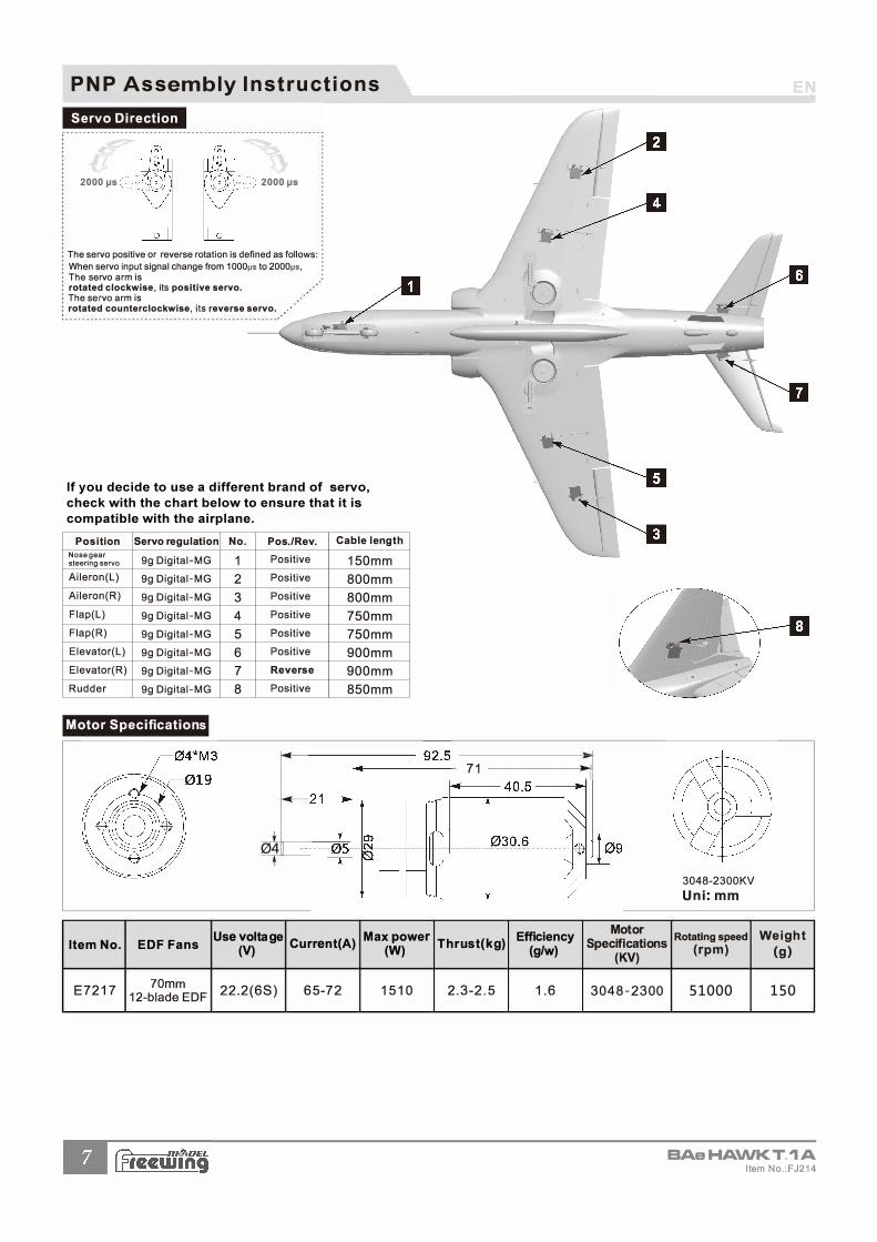
Servo Direction
2000 IJS 2000 IJS
The servo positive or reverse rotation is defined as follows: : When servo input signal change from 1 000µs to 2000µs, : The servo arm is rotated clockwise, its positive servo. The servo arm is rotated counterclockwise, its reverse servo.
Position Servo regulation No. Pos./Rev. Cable length
Nose gear 9g Digital-MG 1 Positive 150mm steering servo
Aileron(L) 9g Digital-MG 2 Positive 800mm Aileron(R) 9g Digital-MG 3 Positive 800mm Flap(L) 9g Digital-MG 4 Positive 750mm Flap(R) 9g Digital-MG 5 Positive 750mm
Elevator(L) 9g Digital-MG 6 Positive 900mm
Elevator(R) 9g Digital-MG 7 Reverse 900mm
Rudder 9g Digital-MG 8 Positive 850mm
Motor Specifications
04
Use voltage Max power Item No. EDF Fans
(V) Current(A)
(W)
E7217 70mm
22.2(6S) 65-72 1510 12-blade EDF
71 -----------ll�I
Efficiency Motor Thrust(kg) (g/w)
Specifications (KV)
2.3-2.5 1.6 3048-2300
3048-2300KV Uni:mm
Rotating speed
( rpm)
51000
EN
Weight
(g)
150
BAeHA\NKT.'IA Item No.:FJ214
If you decide to use a different brand of servo, check with the chart below to ensure that it is compatible with the airplane.

PNP Assembly Instructions EN
Directional Control Test
After the build is complete, power up the radio, ensure the throttle is in the lowest position, engage the kill switch if one is assigned and connect a fully charged battery to the ESC. Use the radio to ensure correct control direction.
Aileron
Stick Left
• --
Elevator
Stick Back
Rudder
Stick Left
Flaps
Flaps down
-
•
�Ill
BAe HA\NK T. 'IA Item No.:FJ214
-
Stick Right
-
-
�
-
-
� • --
Stick Forward
-
-
�
Stick Right
-
•
PNP Assembly Instructions EN
•·di htitti
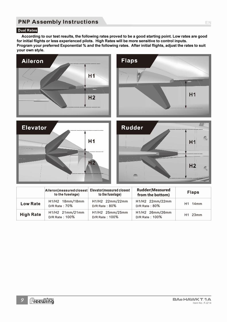
Aileron(measured closest Elevator(measured closest to the fuselage) to the fuselage)
Low Rate H1/H2 18mm/18mm H1/H2 22mm/22mm
D/R Rate : 70% D/R Rate : 80%
High Rate H1/H2 21 mm/21 mm H1/H2 25mm/25mm
D/R Rate : 100% D/R Rate : 100%
Rudder(Measured from the bottom)
H1/H2 22mm/22mm
D/R Rate : 80%
H1/H2 26mm/26mm
D/R Rate : 100%
Flaps
H1 14mm
H1 23mm
BAeHA\NKT.'IA Item No.:FJ214
According to our test results, the following rates proved to be a good starting point. Low rates are goodfor initial flights or less experienced pilots. High Rates will be more sensitive to control inputs.Program your preferred Exponential % and the following rates. After initial flights, adjust the rates to suityour own style.

Freewing Model Co.,Ltd
http://www.freewing-model.com