bag: a code for predicting the performance of a gas bag impact
TRANSCRIPT

SANDIA REPORT SAND93–2133 UC–705 Unlimited Release Printed November 1993
RECORD COPY
c.1
BAG: A Code for Predicting the Performance of a Gas Bag Impact Attenuation System for the PATHFINDER Lander
J. Kenneth Cole, Donald E. Waye
Prepared by Sandia National Laboratories Albuquerque, New Mexico 87185 and Livermore, California 94550 for the United States Department of Energy under Contract DE-AC04-94AL85000
SF2900Q(8-81)
II I I II II II I I II II II SANDIA NATIONAL
LABORATORIES TECHNICAL LIBRARY

Issued by Sandia National Laboratories, operated for the United States Department of Energy by Sandia Corporation. NOTICE: This report was prepared as en account of work sponsored by an agency of the United States Government. Neither the United States Govern- ment nor any agency thereof, nor any of their employees, nor any of their contractors, subcontractors, or their employees, makes any warranty, express or implied, or assumes any legal liability or responsibility for the accuracy, completeness, or usefulness of any information, apparatus, product, or process disclosed, or represents that its use would not infringe privately owned rights. Reference herein to any specific commercial product, process, or service by trade name, trademark, manufacturer, or otherwise, does not necessarily constitute or imply its endorsement, recommendation, or favoring by the United States Government, any agency thereof or any of their contractors or subcontractors. The views and opinions expressed herein do not necessarily state or reflect those of the United States Government, any agency thereof or any of their contractors.
Printed in the United States of America, This report has been reproduced directly from the best available copy.
Available to DOE and DOE contractors from Office of Scientific and Technical Information PO BOX 62 Oak Ridge, TN 37831
Prices available from (615) 576-8401, FTS 626-8401
Available to the public from National Technical Information Service US Department of Commerce 5285 Port Royal Rd Springfield, VA 22161
NTIS price codes Printed copy A04 Microfiche copy AO1

SAND93-2133
Unclassified Printed November 1993
Unlimited Release Category UC-705
BAG: A Code for Predicting the Performance of a
Gas Bag Impact Attenuation System for the
PATHFINDER Lander
J. Kenneth Cole Flight Dynamics Department
Donald E. Waye Parachute Technology
and Unsteady Aerodynamics Department
Sandia National Laboratories Albuquerque, New Mexico 87185
Abstract
The National Aeronautics and Space Administration (NASA) is planning to launch a network of scientific probes to Mars beginning in late 1996. The precursor to this network will be PATHFINDER. Decelerating PATHFINDER from the high speed of its approach to Mars will require the use of several deceleration techniques working in series. The Jet Propulsion Laboratory (JPL) has proposed that gas bags be used to cushion the payload’s ground impact on Mars. This report presents the computer code, BAG, which has been developed to calculate the pneumatic perfor- mance of gas bag impact attenuators and the one-dimensional rigid-body dynamic performance of a payload during ground impact.
3

Acknowledgments The authors wish to acknowledge:
The Jet Propulsion Laboratory (JPL) who presented Sandia with the project and provided the funding.
Tom Rivellini and Brian Muirhead of JPL who were the principal technical in- terfaces with Sandia.
Chris Hailey who provided managerial support for the project and encourage- ment toward the writing of this report.
Larry Whinery and Dan Luna who built the test gas bags and helped rig and operate the impact test apparatus.
Bob Croll, Ed Clark, Don MacKenzie, John Henfling and Buddy Lafferty who instrumented and operated the impact test apparatus in the High Altitude Chamber.
Dave Bello and Dave Armistead who provided instrumentation for the impact test apparatus in the High Altitude Chamber.
Ed Constantineau who implemented the design, fabrication and installation of the impact test apparatus in the High Altitude Chamber.
4

Table of Contents
1. 2.
3.
4. 6. 6.
7.
8.
List of Figures . . . . . . . . . . . . . . . . . . . . . . . . . . . . . . . . . . . . . . . . . . . . . . . . . . . . . . . . . . . . . . . . . . . . . . . . . . . . . . . . . . . . . . . . . . . . . . . . . . . . . . . . . . . 7
List Of Variables . . . . . . . . . . . . . . . . . . . . . . . . . . . . . . . . . . . . . . . . . . . . . . . . . . . . . . . . . . . . . . . . . . . . . . . . . . . . . . . . . . . . . . . . . . . . . . . . . . . . . . . . 9
Introduction . . . . . . . . . . . . . . . . . . . . . . . . . . . . . . . . . . . . . . . . . . . . . . . . . . . . . . . . . . . . . . . . . . . . . . . . . . . . . . . . . . . . . . . . . . . . . . . . . . . . . . . . . . . . . . 13
Governing Equations . . . . . . . . . . . . . . . . . . . . . . . . . . . . . . . . . . . . . . . . . . . . . . . . . . . . . . . . . . . . . . . . . . . . . . . . . . . . . . . . . . . . . . . . . . . . . . . 15
2.1. Dynamic Equations . . . . . . . . . . . . . . . . . . . . . . . . . . . . . . . . . . . . . . . . . . . . . . . . . . . . . . . . . . . . . . . . . . . . . . . . . . . . . . . . . . . . . . . . . . 15
2.2. Gas Dynamics Equations . . . . . . . . . . . . . . . . . . . . . . . . . . . . . . . . . . . . . . . . . . . . . . . . . . . . . . . . . . . . . . . . . . . . . . . . . . . . . . . . 17
2.3. Discharge Coefficient . . . . . . . . . . . . . . . . . . . . . . . . . . . . . . . . . . . . . . . . . . . . . . . . . . . . . . . . . . . . . . . . . . . . . . . . . . . . . . . . . . . . . . . 20
2.4. Change in Bottom Bag Area And Volume . . . . . . . . . . . . . . . . . . . . . . . . . . . . . . . . . . . . . . . . . . . . . . . . . . . . . . 21
2.5. Bounce Equations . . . . . . . . . . . . . . . . . . . . . . . . . . . . . . . . . . . . . . . . . . . . . . . . . . . . . . . . . . . . . . . . . . . . . . . . . . . . . . . . . . . . . . . . . . . . 24
Calculational Procedure . . . . . . . . . . . . . . . . . . . . . . . . . . . . . . . . . . . . . . . . . . . . . . . . . . . . . . . . . . . . . . . . . . . . . . . . . . . . . . . . . . . . . . . . . . 27
3.1. Initialization . . . . . . . . . . . . . . . . . . . . . . . . . . . . . . . . . . . . . . . . . . . . . . . . . . . . . . . . . . . . . . . . . . . . . . . . . . . . . . . . . . . . . . . . . . . . . . . . . . . . . 27
3.2. Approximate Calculations . . . . . . . . . . . . . . . . . . . . . . . . . . . . . . . . . . . . . . . . . . . . . . . . . . . . . . . . . . . . . . . . . . . . . . . . . . . . . . . 28
3.3. Improved Calculations . . . . . . . . . . . . . . . . . . . . . . . . . . . . . . . . . . . . . . . . . . . . . . . . . . . . . . . . . . . . . . . . . . . . . . . . . . . . . . . . . . . . . 30
Input . . . . . . . . . . . . . . . . . . . . . . . . . . . . . . . . . . . . . . . . . . . . . . . . . . . . . . . . . . . . . . . . . . . . . . . . . . . . . . . . . . . . . . . . . . . . . . . . . . . . . . . . . . . . . . . . . . . . . . . . . 36
output . . . . . . . . . . . . . . . . . . . . . . . . . . . . . . . . . . . . . . . . . . . . . . . . . . . . . . . . . . . . . . . . . . . . . . . . . . . . . . . . . . . . . . . . . . . . . . . . . . . . . . . . . . . . . . . . . . . . . . 39
Code Validation . . . . . . . . . . . . . . . . . . . . . . . . . . . . . . . . . . . . . . . . . . . . . . . . . . . . . . . . . . . . . . . . . . . . . . . . . . . . . . . . . . . . . . . . . . . . . . . . . . . . . . . . 41
6.1. Adiabatic Compression Check . . . . . . . . . . . . . . . . . . . . . . . . . . . . . . . . . . . . . . . . . . . . . . . . . . . . . . . . . . . . . . . . . . . . . . . . . 41
6.2. Comparison With Test Data . . . . . . . . . . . . . . . . . . . . . . . . . . . . . . . . . . . . . . . . . . . . . . . . . . . . . . . . . . . . . . . . . . . . . . . . . . . . 43
Summary And Recommendations . . . . . . . . . . . . . . . . . . . . . . . . . . . . . . . . . . . . . . . . . . . . . . . . . . . . . . . . . . . . . . . . . . . . . . . . . . . 47
References . . . . . . . . . . . . . . . . . . . . . . . . . . . . . . . . . . . . . . . . . . . . . . . . . . . . . . . . . . . . . . . . . . . . . . . . . . . . . . . . . . . . . . . . . . . . . . . . . . . . . . . . . . . . . . . . 49
Appendix A. Example of the Input . . . . . . . . . . . . . . . . . . . . . . . . . . . . . . . . . . . . . . . . . . . . . . . . . . . . . . . . . . . . . . . . . . . . . . . . . . 61
Appendix B: Example of the Output . . . . . . . . . . . . . . . . . . . . . . . . . . . . . . . . . . . . . . . . . . . . . . . . . . . . . . . . . . . . . . . . . . . . . . . 53
Distribution . . . . . . . . . . . . . . . . . . . . . . . . . . . . . . . . . . . . . . . . . . . . . . . . . . . . . . . . . . . . . . . . . . . . . . . . . . . . . . . . . . . . . . . . . . . . . . . . . . . . . . . . . . . . . . 57
List of Figures
Figure 1: Sketch of the Payload and the Gas Bag ImpactAttenuation System .................................................................................... 14
Figure 2: Flow Coefficients for Sharp-Edged Orifice .................................................. 20Figure 3: Regions Involved in the Calculation of the Footprint Area ...................... 22Figure 4: Piston-Cylinder Decelerator ....................................................................... 41Figure 5: Comparison of Acceleration Data and Predictions ................................... 45
Figure 6: Comparison of Pressure ‘I&t Data with Predictions ................................. 46

List Of Variables
a
~*
A
AFP
AEX
AIN
AINT
AsEG
DC
DWl
DW2
E
g
gplanet
h
k
m
M
P
R
RG~
linear acceleration of the payload (meters/secondz)
speed of sound in gas (meters/second)
area (meters2)
area of the bottom bag’s footprint on the ground (meters2)
total area of orifices connecting the bottom bag with the outsideenvironment (meters2)
total area of orifices connecting the bottom bag with the top bags(meters2)
area of the intersection of overlaps, used in calculating footprint area(meters2)
area of a circular segment, used in calculating footprint area(meters2)
distance between the centers of the spherical lobes that define the bagshape (meters)
mass of gas flowing through the external orifices per print interval(grams), flow into the bottom bag is positive
mass of gas flowing through the internal orifices per print interval(grams), flow into the bottom bag is positive
energy or work (Joules)
acceleration of gravity on earth (meters/second2)
acceleration of gravity on the planet impacted (meters/second2)
height above the ground (meters)
discharge coefficient for an orifice
mass of the payload (kilograms)
Mach number
pressure (Pascals, Newtons/mete#)
constructed radius of the three spherical shapes that are used todefine the gas bag shape (meters)
gas constant (Joules/(tilogram-mole K))
9

sT
t
At
u
u
AU
v
w
x
1#1~
crush distance or stroke (meters)
gas temperature (IQ
time (seconds)
time increment used in calculations (seconds)
velocity of gas (meters/second)
velocity of the payload (meters/second)
increment in velocity of the lander (meters/second)
volume (meters3)
total mass of gas contained in the bottom bag or all of the top bags(kilograms)
distance from ground to the plane containing the centers for thethree spheres that define the trilobe shape of the bottom bag (meters)
R, constructed radius of a spherical lobe of the gas bag (meters)
Greek Svmbolq
B = ratio, (X&)
1’ = ratio of specific heats, (C~CV), 1.4 for ideal nitrogen
P = density of gas (kilograms/meter3)
Actual =
Bag =
BagI =
Bounce =
d =
EX =
true condition
condition in the bottom bag
initial condition in the bottom bag
condition associated with the rebound of the payload
conditions downstream of present position
property of the orifices between the bottom bag and the localenvironment, when used to subscript& it refers to the total area ofthese orifices
10

FP = property of the footprint of the bottom bag on the ground, when usedto subscript ~ it refers to the area of the footprint
I = initial condition
IN = property of the orifices between the bottom bag and the top bagswhen used to subscript ~ it refers to the total area of these orifices
INT = property of bag footprint where there is an intersection of overlapamong the circular footprints of the three spherical lobes
o = local atmospheric condition
Piston = property of the piston
Planet = property of the planet
SEG = relates to a circular segment, used in calculating footprint area
sub = property of a subsonic orifice flow
sonic = property of a sonic orifice flow
Res = condition in the reservoir, i.e., the top bags
ResI = initial condition in the reservoir, i.e., the top bags
th = conditions in the throat of an orifice, the region of smallest flow area
Theoretical= condition predicted by a theory
u = conditions upstream of present position
1 = value of variable at time, t, the current value
2 = value of variable at time, t+At, the predicted value
11

12
L Introduction
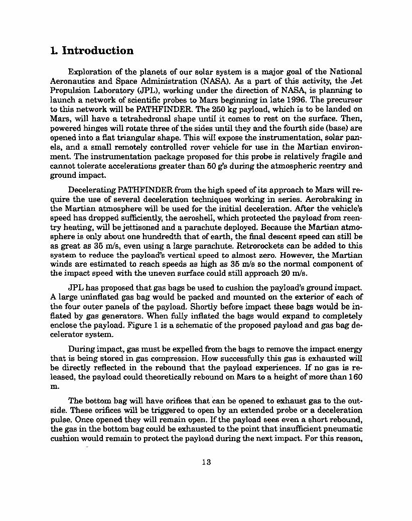
Exploration of the planets of our solar system is a major goal of the NationalAeronautics and Space Administration (NASA). As a part of this activity, the JetPropulsion Laboratory (JPL), working under the direction of NASA, is planning tolaunch a network of scientific probes to Mars beginning in late 1996. The precursorto this network will be PATHFINDER. The 260 kg payload, which is to be landed onMars, will have a tetrahedronal shape until it comes to rest on the surface. Then,powered hinges will rotate three of the sides until they and the fourth side (base) areopened into a flat triangular shape. This will expose the instrumentation, solar pan-els, and a small remotely controlled rover vehicle for use in the Martian environ-ment. The instrumentation package proposed for this probe is relatively fragile andcannot tolerate accelerations greater than 50 g’s during the atmospheric reentry andground impact.
Decelerating PATHFINDER from the high speed of its approach to Mars will re-quire the use of several deceleration techniques working in series. Aerobraking inthe Martian atmosphere will be used for the initial deceleration. After the vehicle’sspeed has dropped sufficiently, the aeroshell, which protected the payload fkom reen-try heating, will be jettisoned and a parachute deployed. Because the Martian atmo-sphere is only about one hundredth that of earth, the final descent speed can still beas great as 36 rids, even using a large parachute. Retrorockets can be added to thissystem to reduce the payload’s vertical speed to almost zero. However, the Martianwinds are estimated to reach speeds as high as 35 m/s so the normal component ofthe impact speed with the uneven surface could still approach 20 n-ds.
JPL has proposed that gas bags be used to cushion the payload’s ground impact.A large uninflated gas bag would be packed and mounted on the exterior of each ofthe four outer panels of the payload. Shortly before impact these bags would be in-flated by gas generators. When filly inflated the bags would expand to completelyenclose the payload. Figure 1 is a schematic of the proposed payload and gas bag de-celerator system.
During impact, gas must be expelled from the bags to remove the impact energythat is being stored in gas compression. How successfully this gas is exhausted willbe directly reflected in the rebound that the payload experiences. If no gas is re-leased, the payload could theoretically rebound on Mars to a height of more than 160m.
The bottom bag will have orifices that can be opened to exhaust gas to the out-side. These orifices will be triggered to open by an extended probe or a decelerationpulse. Once opened they will remain open. If the payload sees even a short rebound,the gas in the bottom bag could be exhausted to the point that insufficient pneumaticcushion would remain to protect the payload during the next impact. For this reason,
13

the bottom bag will also contain a diaphragm and each top bag will be connected tothe bottom bag by permanently open orifices. During any rebound then, the top bagscan recharge the bottom bag and the diaphragm will prevent their gas from beinglost through the external orifices.
+xDirection
I
Figure k Sketchof the Payloadand the GasBagImpactAttenuationSystem
The purpose of this report is to present a computer code that has been devel-oped to calculate the pneumatic performance of gas bags and the rigid-body dynamicperformance of the payload during ground impact. Chapter 2 contains the develop-ment of the governing equations. Chapter 3 exhibits the organization of the code.Chapter 4 and 5 presents the input requirements and the expected output, respec-tively. Chapter 6 presents the results of several methods that were used to validatethe code.
14

2.Governing Equations
In this chapter, the equations which govern the rigid-body dynamics of the paY-load and the pneumatic performance of the gas bag impact attenuator are derived.The following assumptions are important to these derivations:
1.
2.
3.
4.
6.
6.
7.
8.
9.
10.
11.
Mass of the gas in the bags and the mass of the bags is neglected in determin-ing payload rigid body dynamics.
Motion is purely one-dimensional. The payload descends and rebounds in thevertical direction only with no out of plane motion.
Nitrogen gas is used in the bags and performs as a perfect gas.
Gas compression and expansion occurs adiabatically within the bags.
Gas conditions of pressure, temperature and density instantaneously adjustand are constant throughout each bag. This is justified because the speed ofacoustic waves inside the bags is many times faster than the maximum im-pact speeds of interest. With an impact speed of 35 nis and a gas temperatureof 288 K (60° F), this speed ratio is 9.9.
The bottom bag volume will change with bag crush up, but not from the bagmaterial stretching.
The top ba~ have equal volumes which remain constant during the impactprocess.
Gas conditions in the bottom bag can and will &Her from conditions in the topbags.
Gas conditions among the three top bags can and will vary with time but, willalways be equal to each other.
No aerodynamic drag of the payload and gas bags is considered.
The flow area of each internal and external orifice is unaffected by bag crushup.
2.1. Dynamic Equations
In Figure 1, it can be seen that the forces acting on the payload consist of th~payload weight acting downward and the pressure force acting upward. APPIY@Newton’s second law, the equation of motion for this system is obtained:
15

EForces = ‘gPlanet - @Bag ‘Po)AFp = ‘a”
Rearranging the equation:
‘FPPO PBag _ ~a
()‘ gpla~et - ~ p “
o
Using finite differences, the acceleration is defined as:
AUa=—
At
and the velocity as:Axu=~.
(1)
(2
(3)
(4)
Applying equation 3 to equation 2, the algorithm for computing the payload’s veloci-ty change is obtained:
(AU = At gP1...~ – A:pfJ(p~-l)).
The velocity change from one time step to the next is defined as:
and the payload position after averaging the velocities, ?lI and U2 is:
X2= X1’(U1+Y)A’ -
(5)
(6)
(7)
16

2.2. Gas Dynamics Equations
The nitrogen gas that is contained in all of the bags is assumed to perform as aperfect gas. Thus, the mass of gas contained in a bag can be calculated, if the gaspressure and temperature and the bag volume are known:
w= pvRGA~T”
(8)
Because all of the top bags communicate pneumatically with and through thebottom bag, the gas contained within them will beat the same pressure and temper-ature before impact. Just before impact, external orifices are to be opened in the bot-tom bag and gas will start flowing out to the local environment from the bottom bagand the gas in the top bags will begin flowing into the bottom bag. At impact, the vol-ume of the bottom bag will begin to decrease. If the external orifices are not too large,the gas pressure in the bottom bag will begin to increase forcing gas back into the topbags as well as to the outside. If the external orifices are too large, the pressure inthe bottom bag will continue to decrease and the gas in the top bags will continue toflow into the bottom bag until the diaphragm expands enough to fill the remainingvolume of the bottom bag. At that time, gas will cease flowing horn the external ori-fices.
In this code it is assumed that no heat is transferred during gas compression orexpansion. Several equations for an adiabatic process for an ideal gas are:
and
where:
()Y
P= PIf?-P~
y-l
()Tpy—=—TI pI
wP = T“
(9)
(lo)
(11)
Gas flow through an orifice can be subsonic or sonic. For a diatomic gas, such as,nitrogen, if the ratio of the static pressure of the gas downstream to that upstream isgreater than 0.5283, the flow will be subsonic up to and in the smallest flow area, the

orifice. If the ratio is smaller than 0.5283, the flow will still be subsonic up to the ori-fice, but sonic in the orifice.l
The kinetic energy of the impacting payload must be transferred into the poten-tial energy of the compressed gas. Thus, the gas bags must operate with an internalpressure that is greater than the local atmospheric pressure to be able to generate aforce which, acting through the deflection of the bag, does work on the payload to de-celerate it. A gas bag impact attenuator system intended for use on another planetcan be tested in the earth’s atmospheric pressure with the intended initial pressuredifferential from the bag interior to the atmosphere, but the external orifices maynot perform as they would on the planet since the pressure ratio across them is sig-nificantly different.
For example, the atmospheric pressure on Mars is about 1.0 kPa (0.145 psia). Ifthe initial internal bag pressure is specified as 13 kPa, the pressure differential is 12kPa and the pressure ratio across an external orifice is 0.077, so the orifice flow issonic. ‘lb conduct an impact test on earth at sea level, the bag internal pressurewould have to be about 113 kPa to obtain the 12 kPa differential. The pressure ratioacross an external orifice would be 0.89 and the orifice flow would be subsonic. Themass of gas discharged through the external orifices and the mass of gas remainingin the bag directly affect the rebound of the payload, so an atmospheric test on earthmight not exhibit the same initial rebound speed as would actually occur on anotherplanet. Of course, the height and time achieved in a rebound depends on the localgravity and aerodynamic drag as well as the initial rebound speed.
The mass flow rate through any orifice is:
g = whP#% “
The gas density at the throat of the orifice is:
PthPth =
@GASTth)
and the gas velocity at the throat in terms of sonic conditions is:
(12)
(13)
‘th = MthUth*, (14)
where:
18

When equations 13-15 are factored into equation
(15)
12, themass flow rate is ex-
pressed in te~ of the pressure
dW .Zt
Since the average gas flowthe stagnation pressure in the
and temperature in the orifice throat.
/kAtflthMth RGA;Tth (16)
within a bag is nearly zero, the static pressure andbag are essentially equal. Then equation 44 from
NACA-il 35 (reference 2) Cm be used to obt~ the static Press~e aS a fu_Iction of thepressure upstream of the orifice.
‘Y
Pth-( )=~+(Y-l)M;h l-Y2
.Pu
(17)
When equation 17 is solved for M and substituted along with equation 10 into equa-tion 16, the equation for the subsonic flow through an orifice is obtained
(18)
For sonic flow in the orifice, it4 = 1.0, and equation 17 reduces to:Y
Pth
()
y+l l-Y (19)—=P. 2’
Substituting equation 10 and 19 into equation 16 and rearranging produces theequation for the sonic flow rate through an orifice.
19

(20)
2.3. Discharge Coefficient
Both equation 18 and 20 depend upon the value of the orifice discharge coeffi-cient, k. Experiments were reported in reference 3 in which the pressure differentialacross a sharp-edged orifice was varied to obtain subcritical (subsonic) and critical(sonic) flow conditions. Figure 2 shows the experimental values of k that were mea-sured as a fi.mction of the ratio of downstream to upstream pressure for the rangefrom 0.0 to 1.0.
Flow Coefficients For Sharp-Edged Orifices0.85
0.80
g.+o
~ 0.758
v
%~ 0.70 i. .. . .. ... ... .. . ... .. . .. . . . .... .. ... ... ... ... ... ... .. ... .. . ... ... ... .
.%
d0.65. ................................................+................
0.600.00 0.20 0.40 0.60 0.80 1.00
Downstream Pressure/Upstream Pressun5
Figure 2: Fiow Coefficients for Sharp-Edged Orifices
Each top bag can exchange gas only with the bottom bag through its internal or-ifices. The total mass of gas contained within the three top bags at time t+At is:
20

wRes2()
= wRe81 -At ~IN
(21)
The mass flow rate, $~, is determined by equation 18 or 20 depending on whetherthe orifice flow is subsonic or sonic. If the pressure differential causes flow from thebottom bag into the three top bags (reservoir), that flOWrate is considered to be neg-ative and equation 21 predicts that the reservoir gains mass.
The bottom bag can exchange gas with the three top bags through the internalorifices and also with the outside through the external orifices. The mass of gas con-tained within the bottom bag at time t+At is:
wBag2= “@’A’([w,N+E)EJ
(22)
The same sign convention is used here. Gas flow out of the bottom bag whetherthrough the internal or external orifices is considered as negative. Thus, flow intothe top bags and to the atmosphere will both cause loss in the mass of gas containedin the bottom bag.
2.4. Change in Bottom Bag Area And Volume
The gas bags proposed for the lander are constructed of fabric and restrainedwith external straps and internal tethers so that each appears to consist of threespherical bags that merge into one. The geometric model selected to represent thebottom bag consists of three equal size spheres whose center spacing, DC, is lessthan twice their radius, R.
As shown in equation 1, the force that acts to decelerate the payload depends di-rectly upon the area of the footprint, AFP,of the bag with the ground. The internalpressure in the bottom bag which is being crushed also depends directly upon thechange in the bag’s volume. Figure 3 shows how the bag footprint will vary as thebag crush up progresses. Note that an implicit assumption made in developing thearea and volume equations is that the parts of the bottom bag not in contact with theground do not move or flex. The distance, X, is defined as:
X= R-S. (23)
Region I is the range of crush up in which there is no overlap of the circular ar-
21

a: Footprint within Region I
Overlap
\
c: Footprint at boundary betweenRegions II and III
b: Footprint at boundary betweenRegions I and II
d: Footprint within Region III
Figure 3: Regions Involvedin the Calculationof the FootprintArea
22

eas of contact with the ground. The range of x for this region is:
J (DC) 2R2X> R2- ~ (w
Region II is the range of crush up in which there is overlap of the circular areas,but no intersection of the overlap areas. The range for this region is:
R~x~fl(25)
Region III is the range of crush up in which where is overlap of the circular ar-eas and also intersection of these overlap areas. The range for this region is:
/
(DC)2R2- ~ 2’X20 (26)
For region I, the area of the footprint is simply three times the area of an indi-vidual footprint.
A FP = 3n(R2 -X2) (27)
and the volume lost by the bottom bag due to crush up is:
AV = ~(2R3-3R2X+fl) . (28)
In region II, the footprint is three times the area of an individual footprint mi-nus the areas of overlap. Note that the area of a circular segment is equal to half ofthe area of one overlap zone.
A~EG = (R2-X2)acos((2J%) -(Dc~~)) ‘2’)
23

and
A - 3n (R2 -X2)-6A~~&FP - (30)
The three-dimensiond geometries involved in the bag crush up become muchmore complex in regions II and III. So a different method is employed to calculatethe volume increment lost between times, t, and ~+At:
When region III is reached, the area of the footprint becomes:
A FP = 37T(R2 –X2) – 6A~EG +A1m
(31)
(32)
The calculation of the area of the intersection of overlaps, AINT,is somewhatcomplicated and was not included in the code formulation. The maximum error pro-duced by neglecting it for the proposed PATHFINDER gas bag geometry with R = 1.2meters and DC . 1.913meters, was less than 0.5 percent.
The same method was used to calculate the volume loss in region III as wasused in region II.
When Xc O,the footprint area is assumed to remain equal to the value for X = O.The volume loss was calculated with the same method as in region II.
These, then, are the equations that are incorporated into the computer modelfor predicting the perform~ce of gas bags decelerating a payload during impactupon a planet or other astronomical body.
The formulation is deliberately slanted toward a particular configuration oflander and gas bags proposed by JPL. If tierent shape bags are to be studied, ifwould be necessary to derive footprint area and volume change relations that moreaccurately describe them. Likewise, if the orifice shapes were changed more appro-priate discharge coefficient data would have to be obtained.
2.5. Bounce Equations
Thegasremaining in the bags after the payload has been successfully arrested,
24

u = o, can still be at a pressure greater than the local atmospheric pressure, so thepayload could experience some rebound (bounce). The same governing equationswhich calculate the transfer of the payload’s kinetic energy into potential energystored in the conipression of the gas can also calculate the reverse transfer of energyfrom the gas to the payload. The maximum velocity for a rebound is achieved at theinstant the gas bag ceases to push on the payload. This is when the gas bag has rein-flated to its original shape, i.e., X = R, or when the pressure in the bag reaches thelocal atmospheric pressure. The height of the bounce, assuming no aerodynamicdrag, is found by simply equating the payload’s kinetic energy at the start of the re-bound with its potential energy at the top of the rebound.
U;ouncehBounce = i&planet
The equation for the total time consumed in this gravitationalfrom the simple motion equations for a constant acceleration.
‘2 UBOunCe‘Bounce
=gpzanet
(33)
bounce is obtained
(34)
The minus sign has been added to compensate for the initial bounce velocity which isdefined as negative.
25

26

3. Calculational Procedure
The calculational procedure used in this code closely parallels the one describedin reference 4:
Step 1
Step 2
Step 3
Step 4
At time, t, an approximate calculation is made to estimate the conditions attime, ~+At, with zero acceleration and no mass flow. The resulting gas prop-erties are then used to calculate mass flow rates through the orifices.
Using the mass flow rates, improved gas properties are calculated and thelander acceleration is calculated. More accurate mass flow rates and gasproperties are then calculated.
The final calculation of the lander acceleration for time, t+ At, is made basedon the more accurate values.
The gas properties and lander velocity and displacement are updated to thevalues calculated in Step 3 and the process returns to Step 1, to begin thecalculations for time, ~+ 2At.
3.1. Initialization
‘Ib start a calculation, a number of variable values are input into the code viaa menu request process. The values of other variables which are seldom changedhave been programmed directly into the code. The code uses these inputted and pro-grammed values to calculate the initial conditions for all of the quantities needed forthe calculations. Current values of the variables, i.e., values at time, t, are denotedby the subscript 1, values predicted for time, t+ At, by subscript 2, and initial valuesby subscript I. To start the time iterational process, the current values are equatedto their initial values.
‘BagI =PIvBagZ
‘GAS TBagI
‘Red =PIvRes
‘GA STRes
U1=(J1xl=XXI
vBagl = ‘BagI
vRes = vRes~
wBagl = WBag~
27

wBag2 = wBag~
wResl = WRe8~
wRes2 = wRe8~
‘BagI‘BagZ = v
BagI
‘RedPRe81 = . .
A FP1
A FP2
‘Resl
= 0.0=0.0
3.2. Approximate Calculations
An approximate calculation to predict the state variables at the time, ~+At,from the known values at time, ~, is made next. This calculation assumes that thereis no mass flow through any of the external or internal orifices ~d no lander acceler-ation.
‘app rox = UIAt
xapprox = xl-Axapproz
The subroutine ARVOL is used to calculate themaining volume of the bottom bag, VBagz.
‘FP1 ‘AFP2z=
2
‘Baglk ‘=—
Bagl‘BagI
pReslk—
Resl =PResI
footprint area, AFP,and the re-
PBagl = PI “~~agl
28

w Bagl‘Bag2 =
‘Bag2
‘Res2 = PResl
w Bagl
PBag2 = vBag2
Note that the mass in the bottom bag at time, ~, is used to estimate the gas den-sity at the next time increment.
PBag2?b—Bag2 =
PBagl
PBag2 = PI~;ag2
(pBagl ‘PBag2JpBag = 2
PRes = PRe~l “
The coding assumes that the bottom bag pressure is never less than the exter-nal pressure. Hence, it does not permit gas to flow back from the outside through theexternal orifices into the bottom bag. This agrees with the actual situation where agreater external pressure would tend to collapse the bag. The pressure ratio acrossthe external orifices is checked to see if the flow will be subsonic or sonic. The actualmass flow calculations are made in subroutine FLOW. The sign convention used isthat flow out of the bottom bag is negative. Thus, the bottom bag will lose gas masswhen the gas flows out through the external orifices.
The mass flow through the internal orifices is calculated next. This flow can besubsonic or sonic and can go in either direction through the internal orifices. Thepressure difference across the orifices is examined first to determine the direction offlow and then the pressure ratio is checked to determine whether the flow is subsonic
29

or sonic. Flow from the bottom bag into the top bags (reservoir) is considered to benegative. This flow direction will cause the bottom bag to again lose mass. After themass flows through the external orifices, DWI, and the internal orifices, DWz, are de-termined, values of the gas properties are recalculated.
‘Bag2 = ‘Bagl +DW1 +DW2
w Res2 = wRe81 -DW2
wBag2~Bag2 =
‘Bag2
w Res2‘Res2 = vRe8
‘Bag2A—
Bag2 =‘BagI
‘Res2?L—
Res2 =‘ResI
PBag2 = PBagZkLag2
(pBagl ‘PBag2 )pBag = 2
3.3. Improved Calculations
Improved calculations are now made using the average values of the bag andreservoir pressures. The lander acceleration based on the average pressures andfootprint area are computed and used to determine an average lander velocity.
30

.
X2=X1-AX
Subroutine ARVOL is used to calculate the new footprint area,A~Pz, and the re-maining gas volume of the bottom bag, ‘Bag2”
(ABagl + ‘Bag2JA Bag = 2
‘Bag2A—Bag2 =
‘BagZ
‘Res2k “=—Res2
PResI
PBag2 = PBagZLLag2
(pBagl ‘PBag2)pBag = 2
Again the mass flow through the external and internal orifices are calculatedusing the most recent average values of the bag and reservoir pressures.
31

‘Res2 = wRe8~ -DWZ
wBag2‘Bag2 = v
Bag2
wRes2‘Res2 = vRe8
‘Bag2A—
Bag2 =‘BagI
‘Res2A—Res2 =
‘ResI
PBag2 = PBagIk~ag2
@Bagl ‘pBag2 )pBag = 2
@Resl ‘PRes2~PRe,q = 2
From these average values, the final calculation of the lander acceleration, ve-locity and position at time, ~+At, are calculated.
AFPPoAt ~Bag _ ~AU =
(
mgP
m P. - AFPpO-)
U2= U1 +AU
.
X2 ‘X++%9A’32

The inertial acceleration of the lander, not including the planet’s gravitationalacceleration, in earth g’s is:
To obtain the rate of change in acceleration:
(i#iFp (AFP2 ‘AFP1 )
z= At9
“W‘-%((:Fp)(E)A~a.-l)+AFpE)’(’Ba.)’--The code then checks to see if bag crush up has progressed to where XSTOP is
reached and the lander payload is beginning to directly impact the ground. If it has,a final print out of conditions is made and the code is exited. If not, the lander veloci-ty is checked. If it is greater than zero, all of the variables are updated, a check ismade to determine if printout is needed, and then the calculations for the next timeincrement are cycled to Step 1, the approximate calculation.
If the lander velocity is less than zero, rebound is occurring. The standard cal-culational process will continue until the pressure in the bottom bag is within 0.1percent of the outside pressure or the bag has reinflated to its original radius. Thenthe last lander velocity that has been computed is used to predict the height andtime duration of the rebound that will occur in a vacuum. This information is printedout and the code is exited.
33

34

4. Input
The input variables that are seldom changed when using the code have beenprogrammed into the code. These variables are:
XSTOP = -0.3 meters
R Bag = 1.2 meters
DC = 1.913 meters,
v BagI = 21.0 meters3
v Res = 63.0 meters3
gPlanet = 3.72653 meters/second2 for Mars
R Gas = 296.929 Joules/(kilogram-mole K)
‘Y = 1.4
-0.10RatiODiaphragm –
OTIME = 0.002 seconds
At = 0.0001 seconds
XSTOP is the X distance in the crush up where the inflated reservoir bags beginto be crushed also. The value of XSTOP could be as large as -1.2 m before thestructure of the full-scale lander would be reached. Thus, a value smaller thanthe maximum also provides a cushion, or margin or error, so that the landerstructure is not reached if a landing happens to be on large pointed rocks.
lil~ag is the constructed radius on one of the three spherical lobes that definesthe shape of each bag.
DC is the distance between the centers for the three spherical lobes that defineeach bag shape.
VBagl is the initial volume of the bottom bag.
Vw~ is the total volume of the three top bags.
gPland is the Pl~et gravitational acceleration, for Mars”
RGm is the gas constant for nitrogen acting as an ideal g%
35

y is the specific heat ratio are for the diatonic gas, nitrogen.
Ra%iaphr~m, the diaphragm ratio, is the fkaction of the initial gas mass inthe bottom bag that is contained between the diaphragm and the internal ori-fices. If conditions cause mass flow from the bottom bag into the top bags, theflOW will stop when the mass of gas above the diaphragm has been trans-ferred.
OZYME is the time required by the external orifices to go from completely closedto fully opened. The cod-ing increases the orifice area linearly with time.
At is the time increment by which the calculations are advanced with each iter-ation. The value of 0.1 millisecond was chosen to insure that the features ofthe external orifice opening could be properly captured.
The code has an input menu which requests values for the variables that havebeen more fi-equently changed in design studies for PATHFINDER. In the order oftheir appearance they are:
G deceleration to activate orifice #l, zILEVEL (<0)-This acceleration level (g’s)must be reached to initiate the opening of the external orifices.Values of-40 g’shave been typically used.
7Jpe Oor 1 to turn check valve off or on - Logic is built into the code for checkvalves to be included in the internal orifices. If the check valve is turned on, noflow can occur from the top bags into the bottom bag. Check valves increase thecomplexity of the bag deceleration system. However, they do permit the pneu-matic volume of the top bags to be used to decrease the pressure rise in the bot-tom bag during impact while also reducing the amount of gas that must beexhausted to minimize rebound. Decreasing the pressure rise decreases the de-celeration g’s,
Qpe Oor 1 to not have or have a diaphragm in the bag - This option permits thefeatures of a diaphragm to be explored.
Total mass of the .latier (kg) - Th.isis the total mass (kilograms) of the lander.
Impact velocity (m/s) - T’h.isis the Velotity (meters/second) of the lander as itimpacts perpendicularly into the ground. This code can not handle oblique im-pacts.
External pressure and initial pressure of bag and reservoir (kPa) .-This is the 10-Cd atmospheric pressure ~d the ifiti~ gas pressure in the bottom bag and thetop bags before the onset of impact in kiloPascals.
Initial temperature ofgas in bag and reservoir (K) - The gas temperature in thebottom and the top bags at the onset of impact in degrees Kevin.
36

Area of orifice #l and #2 (m?,)- The sum of flow areas in square meters for all ofthe external orifices (#1 ) and for all of the internal orifices (#2) when fully open.
This completes the input required by the BAG code. A sample input is containedin Appendix A.
37

38

50output
The code is written in FORTRAN ~d typically runs a solution in less than 2seconds on a SUN SPARC station IPC workstation. Its output begins with thetitle of the code and a listing of all of the values ~put via its menu requestprocess. Then the following column headings appear:
TIME time from the start of impact in milliseconds,
u lander payload velocity in meters/second,
Ax axial acceleration in earth g’s,
XII amount of bottom bag crush up in meters,
PBAG pressure in the bottom bag in kiloPascals,
PRES pressure in the reservoir (top bags) in kiloPascals,
VBAG gas volume remaining in the bottom bag in cubic meters,
DW1 increment of mass in grams transferred into the bottom bagthrough the external orifices since the time of the previousprintout, DW1 <0.0,
DW2 increment of mass in grams transferred into the bottom bagthrough the internal orifices since the time of the previousprintout, -w< DW2<C0,
ACCDOT rate of change of the acceleration in earth g’s/second,
WBAGD mass of gas remaining between the external orifices and thediaphragm in grams, when this reaches zero, flow through theexternal orifices ceases,
WDIAP mass of gas remaining in the bottom bag between the internalorifices and the diaphragm in grams, when this reaches zero,flow through the internal orifices into the reservoir ceases.
Note that this printout is 108 characters wide. When printedonstandmd81/2 by 11inch paper, the quantities WBAGD and WDIAP do not appear.
Two endings to the output are possible. If the input parameters are sized sothat, XD<R - XSTOP, i.e., the gas bag margin of error in crush up is not exceeded and
39

the code will compute until xD returns to zero or the pressure in the bottom bagreaches 1.001 of the local atmospheric pressure. At that point another row of columntitles and the following quantities will be printed:
Duration of bounce
Height of bounce
Minimum X reached
Maximum Acceleration
time in seconds from when the lander and bagsrebound born the impact surface until the secondimpact, assumes no aerodynamic drag andplanetary gravity.
altitude (meters) reached by rebound, assumes noaerodynamic drag and planetary gravity.
smallest distance (meters) to the ground from thereference plane that contains the centers that definethe initial spherical trilobe shape of the gas bag.
largest acceleration (g’s) seen by the lander duringthe impact.
—
If XD >R -XSTOP,the gas bag margin of error in crush up is exceeded and thecode stops calculating and exits. The output is truncated at the last conditionscalculated and no other output will appear.
A sample output is contained in Appendix B. Note that pound signs (#) areused to start each line of the alpha-numeric output. This artifice permits the data tobe plotted by the code, TempleGraph.
40

6.Code Validation
Code validation is an essential part of code development. The BAG codecontains a number of nonlinear features which interact to make it difficult tovalidate its performance.
Consequently, the code’s three subroutines, ARVOL, FLOW and KVAL weretested individually to ascertain that they function in the intended matter. The codewas used then to calculate the deceleration of a mass by the adiabatic compression ofa gas contained within a constant area piston-cylinder. No gas was assumed to betransferred during the deceleration.
Finally, the complete code was used to compute the performance of gas bagsdecelerating a payload with a varying footprint area and mass transfer throughinternal and external orifices. These results were compared with data from testsperformed on a 0.38-scale lander gas bag impact attenuation system in the San&aNational Laboratories High Altitude Chamber.
6.1. Adiabatic Compression Check
A free piston moving into a closed cylinder will be decelerated by theincreasing pressure of the gas trapped in the cylinder and undergoing adiabaticcompression. Figure 4 is a schematic of the pistordcylinder arrangement.
I+U
Figure 4: Piston-Cylinder Decelerator
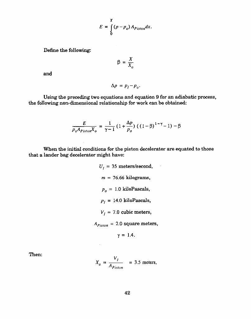
Work performed on the gas by the moving piston:
41
x
E= J( P – Po)Api~to~dX”o
Define the following
Bx‘q
and
Ap = pl–po.
Using the preceding two equations and equation 9 for an adiabatic process,the following non-dimensional
E
PoAPistonxo
relationship for work can be obtained.
((l-p) l-~-l)-p
When the initial conditions for the piston decelerator are equated to thosethat a lander bag decelerator might have:
u,=35meters/second,
m = 76.66 tiOgI’&311M,
Po = 1.0 kiloPascals,
PI = 14.0 kiloPascals,
v, = 7.o cubic meters,
APiSton= 2.0 square meters,
Y = 1.4.
Then:VI
X. = = 3.5meters,APiston
42

. Ap = 13.0kiloPascals.
Subroutine ARVOL in the BAG code W= modified to output the fmtpfint areaas a constant 2.o square meters and to calculate the cylindrical volme ~ the pistonmoved toward the closed end. When the preceding initial conditions were tiput intoBAG, it predicted a maximum piston stroke of 1.2994 meters. Hence,
P1.2994— = 0.3713
= 3.50
and with this the theoretical adiabatic equation predicted the non-dimensional workas
(E) = 6.76832PoAPistonxo Theoretical
and:
ETheoretical = 47378.3 Joules.
The actual kinetic energy of the piston which was input to the code was
mU;E—Actual = z = 46954.3Joules.
From this comparison, it appears that the code slightly overpredicted themaximum stroke required to transfer the initial kinetic energy of the piston into thestored potential energy of the compressed gas. The error between the actual and thetheoretical energy is about 0.9 percent.
6.2. Comparison With Test Data
A 0.38-scale model of a lander and gas bags with internal and extern~ orifices
was tested with an impact apparatus specially constructed inside the Sandia Nation-al Laboratories High Altitude Chamber. This apparatus codd generate norm~ im-
43

14
13
12
8
7
6
_..-.....+ ..........
-.--- +-.-....
_.-...-.-&..........
/,,
. .. ....... ..........
_.-..-....:. ..........
! ! ! ! I I I I
Code. without Varying External Orifke Area—- —- —__________________
.-- . . . . . . ..\.. -.--. ---..\ -.---------.------------+----------- Z* wj~ yyq E_~al_~=_Ay
Hi@ Altiturk Chamber Prea.me Traducer #1
KIgb A1titu& Chamber Preaaure Trmsducer #5. . . . . . . . . . . . . . . . . . . . . . . .. . . . . . . . . . . . +.-- . -.....-+. . . . . . . . . . . ————— ————— ——
ImpactVelt@y = 20.f7 m/s ~-.~.--~
. -<1................. -4:---:--+-:~“~ : : : :.....-.<............. .........+.... ..... ........ .......+.... .....-
<
;-T- ;.
!!ni;~Ld~’’r}\:H~---------:-----------------...................-:....-.......”..- ........-----------------..........--------\; \:
. <.----L -W% ; + :\ i:.“----------~--”-----~-~. :\%,.........................................\.......T..- .%...:... . . . . . . . . . . . . . . . . . . .-
‘%. ! ,., \: !-\ :\: \;
%.:
:+:” ;:\........-.............. -r.... . . . . . . . ix.--..+................................-...-1......-
.
:.: $~‘-”----‘\\ : .:
\“& \,<
-----------~------------/-----------;------------{-:~<------~------------:-----------4----------------\\\ :
“w
o 10 20 30 40 50 60 70 80 90 100 110
Time FromImpact(ins)
Figure 6: Comparison of Pressure Test Data with Predictions

7. Summary And Recommendations
1.
2.
3.
4.
6.
6.
7.
8.
9.
10.
A computer code has been developed to predict the one-dimensional rigid-bodydynamics of a payload being decelerated by gm bags m it impacts the ground.
The gas in the bags was assumed to be nitrogen, acting as a perkct gas.
Gas compression and expansion during bag crush UP ~d any subsequent re-bound were assumed to be adiabatic processes.
Gas flow between the bottom bag md the top b~ WaS permitted through in-ternal orifices. These orifices were always open. Subsonic and sonic flows inthe orifices were possible.
Gas flow ii-em the bottom bag to the outside was permitted through externalorifices which could be opened when the payload deceleration reached a pre-scribed level. Subsonic and sonic flows were possible in these orifices.
A diaphragm was incorporated into the code. This diaphragm was locatednorth bottom bag and served to prevent all of the gas from the bottom and tea-pots being vented through the external orifices during a rebound. Thus, sea-beds would be able to still provide some protection during a second andsubsequent impacts.
The area of the ba<s footprint on the ground and the gss volume remainingwere modeled as the bottom bag was crushed up in the impact.
The code was validated for two cases. The first was a piston decelerating ingas filled, closed end cylinder. The code calculated a maximum stroke whichimplied a piston kinetic energy that was within 0.990 of the theoretical value.The second case was a comparison with actual test data from a 0.38-scalelander payload and gas bags. The agreement for this complicated case wasvery reasonable.
The BAG code appears to do a very adequate job of predicting the performanceof a payload and gas bag decelerator. It is coded in FORTRAN and runs in lessthan 2 seconds on a SUN SPARCstation IPC workstation. It can be a very use-fti design tool.
The predictive capabilities of the code could be enhanced by incorporating afeature that would allow the bottom bag to flexor move relative to the payloadas impact is occurring. The present model assumes that the parts of the bot-tom bag not in contact with the ground do not move relative to the payload.This causes the predicted accelerations and pressures to be too lmge and theimpact duration too short.
47

48

8. References
[1] Iiiepmann, H. W. and Roshko, A., Elements of Gas Dynamics, John Wiley& Sons,1957.
[2] Ames Research St@ Equations, Tables and Charts for Compressible Flow, Na-tional Advisory Committee for Aeronautics, Ames Aeronautical Laboratory Re-port 1135.
[s1perry, J. A., Jr., Critical F1OWThrough Sharp-Edged Orifices, Transactions of theAmerican Society of Mechanical Engineers, October 1949, pp. 757-764.
[4] Esgar, Jack B. and Morgan, William C., Analytical Study of Soft Landings onGas-Filled Bags, NASA Lewis Research Center, Cleveland, Ohio, ‘Ikchnica.l Re-pOI’t R-75, March 16,1960.
49

50

Appendix A Example of the Input
!l%is example is for a version of the BAG code where the programmed initialvalues are arranged to compute impact testing of a 0.38-scale model test on theearth. This version of the code is called SBAG.E. The programmed initial v~ues are:
XSTOP = –0.114meters
R Bag = 0.456
DC = 0.727
v BagZ = 1.162
vRes = 3.457
meters
meters3
meters3
gpla~~t = 9.80665 meters/second2 for Earth
‘Gas = 296.929 Joules/(kilogram-mole K)
Y = 1.4
‘atioDiaphragm = 0.10
OTIME = 0.002 seconds
At = 0.0001 seconds
The following shows each question asked by SBAG_E and then the responseprovided by the user:
G DECELERATION TO ACTIVATE
-40.
TYPE O OR 1 TO TURN CHECK
o
TYPE O OR 1 TO NOT HAVE OR
ORIFICE #1, ALEVEL (<0)
VALVE OFF OR ON
HAVE A DIAPHRAGM IN THE BAG
1
TOTAL MASS OF THE LANDER (KG)27.66
IMPACT VELOCITY (M/S)
20.67
EXTERNAL PRESSURE AND INITIAL PRESSURE OF
BAG AND RESERVOIR (KPA)
1.99 12.0
INITIAL TEMPERATURE OF GAS IN BAG AND RESERVIOR (K)273.
AREA OF ORIFICE #1 AND #2 (M2)
0.13 0.26
51

After the orifice areas are input the code pefiorm tie requested calculations.The output is shown in Appendix B.
52

Appendix B: Example of the Output
The output that is shown resulted from running a version of the BAG codewhich had its programmed input variables arranged for a impact test on earth of a0.38-scale model of the lander payload and gas bag impact attenuation system. Theprogrammed and requested input are shown in Appendix A.
53

# CODE SBAG_E## AMASS= 27.660 KG UI=
## BAG VOLUME= 1.152 M3
20.670 M/S MAX DEFLECTION= -0.114 M
RESERVIOR VOLUME= 3.457 M3
## ALEAK1=## AMBIENT## INITIAL#
0.130 M2 ALEAK2= 0.260 M2
PRESSURE= 1.990 KPA INITIAL BAG PRESSURE= 12.000 IQA
BAG TEMPERATURE= 273. K
# GAS MASS OUTSIDE DIAPHRAGM= 153.5 GM GAS## BAG RADIUS IS 0.456 M DISTANCE BETWEEN
## ORIFICE 1 OPENS WHEN DECELERATION EXCEEDS## CHECK VALVE IS INOPERATIVE IN ORIFICE #2## A DIAPHRAGM IS INSTALLED
o-lI& #
## TIME# (s)
0.00100.00200.00300.00400.00500.00600.00700.00800.00900.01000.01100.01200.01300.01400.01500.01600.0170
u AX(M/S) (G’S)20.648 -6.10120.565 -12.26720.422 -18.19720.223 -23.90919.968 -29.42019.661 -34.73919.302 -39.87118.895 -44.56018.447 -48.31117.967 -51.06917.463 -53.43116.937 -55.58516.391 -57.53115.828 -59.25215.248 -60.75214.655 -62.04514.050 -63.149
[N THE BAG
XD(M)
0.0210.0410.0620.0820.1020.1220.1420.1610.1790.1970.2150.2320.2490.2650.2810.2960.310
PBAG(KPA)12.01412.05312.11712.20312.30912.43412.57412.66712.61612.50812.45712.44612.45712.47312.49012.50412.514
MASS INSIDE DIAPHRAGM=
CENTERS IS 0.727 M
-40.000 G
PRES(KPA)12.00412.01712.03812.06612.10312.14712.19812.25512.31012.35212.38212.40312.42012.43712.45412.47012.486
VBAG(M3)1.1501.1451.1361.1251.1101.0941.0751.0541.0321.0090.9840.9590.9340.9080.8830.8580.833
DW1
(GM)0.000.000.000.000.000.000.00
-0.59-2.22
-3.25-3.25-3.24-3.24-3.25-3.25-3.25-3.26
17.1 GM
DW2 ACCDOT
(GM) (G’S/S)-0.13 -6293.20-0.39 -6043.93-0.63 -5818.01-0.88 -5609.98-1.11 -5414.20-1.34 -5225.40–1.55 -5038.56-1.73 -4266.93-1.65 –3288.90-1.28 –2476.66-0.89 -2241.18-0.64 -2048.30-0.53 -1832.68-0.51 -1608.55-0.51 -1394.54-0.50 -1197.01-0.47 -1016.66
WBAGD
(GM)153.48153.48153.48153.48153.48153.48153.48153.02150.97
147.75144.50141.25138.01134.77131.52128.26125.01
WDIAP(GM)16.9516.5915.9815.1314.0412.7311.209.487.81
6.495.564.904.37
3.863.362.862.39

0.01800.01900.02000.02100.02200.02300.02400.02500.02600.02700.02800.02900.03000.03100.03200.03300.03400.03500.03600.03700.0380
E 0.03900.04000.04100.04200.04300.04400.04500.04600.04700.04800.04900.05000.05100.05200.05300.05400.05500.05600.05700.0580
13.436 -64.08212.813 -64.86212.183 -65.51111.547 -66.05310.907 -66.49510.263 -66.8139.616 -67.0098.968 -67.0878.320 –67.0387.673 -66.8907.028 -66.6496.386 -66.3175.747 -65.8995.113 -65.4024.484 –64.8323.861 -64.1963.245 –63.5012.636 -62.7562.034 -61.9661.440 -61.1340.854 -60.2650.278 –59.364
-0.290 -58.433-0.849 -57.478-1.398 -56.503-1.937 -55.511-2.467 -54.505-2.987 -53.491-3.496 -52.470-3.996 -51.442-4.486 -50.409-4.965 -49.372-5.434 -48.332-5.893 -47.290-6.342 -46.247-6.781 -45.204-7.209 -44.161-7.627 -43.119-8.035 -42.079-8.433 -41.040-8.820 -40.004
0.0590 -9.198 -38.969
0.3240.3370.3490.3610.3720.3830.3930.4020.4110.4190.4260.4330.4390.4450.4490.4530.4570.4600.4620.4640.4650.4660.4660.4650.4640.4620.4600.4570.4540.4500.4460.4410.4360.4310.4250.4180.4110.4040.3960.3870.3790.370
12.52112.52512.52612.52712.52612.51912.50312.47712.44112.39612.34212.27812.20512.12312.03211.93211.82411.70911.58711.45811.32311.18411.04010.89210.74110.58710.43110.27410.1169.9589.7999.6419.4849.3289.1749.0228.8738.7268.5828.4418.3048.171
12.50012.51112.51912.52312.52212.51712.50912.49712.48012.46012.43412.40512.37012.33212.28912.24212.19012.13512.07512.01211.94611.87611.80211.72611.64711.56511.48011.39411.30511.21411.12211.02710.93210.83510.73710.63810.53810.43810.33710.23610.13410.033
0.8080.7850.762
0.7390.7180.6980.6790.6610.6440.6290.6150.6010.5900.5790.5690.5610.5540.5490.5440.5410.5380.5370.5370.5380.5400.5440.5480.5530.5600.5670.5750.5850.5950.6060.6180.6310.6440.6580.6740.6890.7060.723
-3.26-3.26-3.26-3.26-3.26-3.26-3.26-3.25-3.24
-3.24-3.22-3.21-3.20-3.18-3.16-3.14-3.11-3.09-3.06-3.03-3.00-2.97-2.94-2.90-2.87-2.84-2.80-2.76-2.73-2.69-2.65-2.61-2.58-2.54-2.50-2.47-2.43-2.39-2.36-2.33-2.29-2.26
-0.42 -854.01-0.34-0.24-0.110.020.140.250.370.490.630.760.901.031.171.301.431.561.681.801.922.032.142.242.342.432.522.602.682.752.822.882.932.993.033.083.113.153.183.203.223.243.26
–711.46
-590.96
–497.13
-382.49-258.85-139.23-21.2598.35
191.51284.53
373.08455.23531.52600.88663.86718.94766.24809.71848.92883.96914.87942.10964.71983.41998.34
1009.711017.781023.961030.311035.071038.971041.371042.691043.481043.401042.861041.781040.341038.411036.391034.38
121.75118.49115.23111.97108.71105.45102.2098.9595.7092.4789.2486.0382.8379.6576.4973.3570.2367.1464.0861.0458.0455.0652.1249.2146.3443.5040.7037.9335.2032.5129.8527.2424.6522.1119.6017.1314.7012.309.947.615.323.05
1.961.611.361.231.241.371.611.972.45
3.063.814.695.716.878.159.57
11.1112.7814.5716.4818.5020.6322.8625.1927.6130.1232.7235.3938.1340.9443.8146.7449.7252.7555.8258.9362.0865.2568.4571.6874.9278.17

0.0600 -9.565
0.0610 -9.926
0.0620 -10.2930.0630 -10.6620.0640 -11.0330.0650 -11.4020.0660 -11.7670.0670 -12.1280.0680 -12.4820.0690 -12.8290.0700 -13.1660.0710 -13.4940.0720 -13.8110.0730 -14.1160.0740 -14.4070.0750 -14.6830.0760 -14.9400.0770 -15.179
0.0780 -15.3970.0790 -15.5940.0800 -15.769
Cnm 0.0810 -15.920
0.0820 -16.0460.0830 -16.1460.0840 -16.219
0.0850 -16.2630.0860 -16.2760.0863 -16.274
# TIME u
##
-37.936
-38.132
-38.597
-38.791
-38.749
-38.501-38.076
-37.498-36.784-35.948-34.999
-33.940
-32.767
-31.468
-30.017-28.323
-26.412
-24.402
-22.290
-20.070
-17.738
-15.285
-12.703
-9.984-7.120
-4.104
-0.932
-0.057AX
0.360
0.3510.3410.3300.3190.3080.2960.2850.2720.2600.2470.2330.2200.2060.1910.1770.1620.1470.1320.1160.1000.0850.0690.0530.0360.0200.004-0.001XD
# DURATION OF BOUNCE= 3.32 S
## MINIMUM X REACHED= -0.010 M
8.0418.1128.2348.3218.3788.4128.4268.4258.4138.3948.3708.3438.3158.2888.2638.2428.2248.2128.2058.2048.2108.2228.2418.2668.2968.3318.3688.379PBAG
9.931
9.8319.7379.6509.5679.4899.4159.3439.2749.2089.1439.0819.0208.9608.9028.8468.7928.7398.6898.6418.5968.5548.5158.4818.4518.4268.4088.404PRES
HEIGHT OF BOUNCE=
0.7410.7590.7770.7970.8160.8360.8560.8760.8970.9170.9380.9580.9780.9981.0171.0351.0531.0691.0851.0991.1121.1231;1331.1411.1461.1501.1521.152VBAG
13.50 M
-2.23
-0.660.000.000.000.000.000.000.000.000.000.000.000.000.000.000.000.000.000.000.000.000.000.000.000.000.000.00DW1
MAXIMUM ACCELERATION= -67.088 G
3.27 1032.58
3.22 -624.623.02 -334.232.84 -79.182.68 142.782.54 334.712.43 500.772.33 645.742.25 774.242.18 891.612.12 1003.242.07 1114.582.02 1232.901.97 1368.541.92 1544.601.87 1863.841.81 1961.131.75 2061.161.68 2165.691.60 2275.831.51 2392.681.41 2517.171.30 2649.861.16 2791.061.01 2940.010.83 3095.020.60 3251.720.60 1142.36DW2 ACCDOT
0.83-0.06-0.06-0.06-0.06-0.06-0.06-0.06-0.06-0.06-0.06-0.06-0.06-0.06-0.06-0.06-0.06-0.06–0.06–0.06–0.06-0.06-0.06-0.06-0.06-0.06-0.06-0.06
WBAGD
81.44
84.6787.7190.5693.2695.8198.25
100.59102.85105.04107.17109.24111.27113.24115.16117.03118.85120.60122.28123.89125.41126.83128.14129.32130.35131.20131.83131.96WDIAP

Distribution
MS0841 1500 D. J. McCloskey
MS0836 1501 C. W. Peterson
MS0827 1502 P. J. Hommert
MS0827 1511 J. S. Rottler
MS0834 1512 A. C. Ratzel
MS0835 1513 R. D. Skocypec
MS0832 1661 W. P. Wolfe
MS0832 1551 J. K. Cole (10)
MS0833 1552
MS0833 1552
MS0833 1662
MS0833 1562
MS0833 1652
MS0826 1553
MS0825 1564
MS0826 1564
MS0443 1561
MS0437 1562
MS0970 9200
MS0979 9204
MS0313 9812
MS9018 8523-2
MS0899 7141
MS0619 7151
MS1119 7613-2
C. E. Hailey
V.L.Behr
J. M. Nelsen
J. H. Stricldand
D. E. Waye (10)
W.L.Herrnina
R. H. Croll
W. H. Rutledge
H. S. Morgan
R.K.ThomasAttn:K. W.Gwinn
T. A. Sellers
L. S. Walker
D. L. Keese,Attn:E. J. Constantineau
Central Technical Files
!lkchnical Library (5)
Tbchnical Publications
Document Processingfor DOE/OSTI (10)
Mr. Robert M. BamfordApplied !lkchnologies SectionJet Propulsion Laboratory4800 Oak Grove DrivePasadena, California 91109-8099
Mr. Brian Muirhead, ManagerMESUR Pathfinder Flight SystemJet Propulsion Laboratory4800 Oak Grove DrivePasadena, California 91109-8099
Mr. Michael O’NealMechanical Systems
Development SectionJet Propulsion Laboratory4800 Oak Grove DrivePasadena, California 91109-8099
Mr. ‘Ibm Rivell.ini (5)Mechanical Systems
Development SectionJet Propulsion Laboratory4800 Oak Grove DrivePasadena, California 91109-8099
57

THISPAGE IEJTEi!WIOMIALYLEF!fBLAiW