bailey engineering 2-step rev limiter: shift and launch ...bailey-eng.com/2step/manual 1.0.1.pdf ·...
TRANSCRIPT

Version 1.0.1
Bailey Engineering 2-Step Rev Limiter:
Shift and Launch Controller
For Turbo Buick, DSM, 3000GT/Stealth, Supra,
Mustang V6, and many more.
2
TABLE OF CONTENTS
Package contents .................................................................................... 3
Warranty and disclaimer ......................................................................... 3
Introduction ............................................................................................ 4
Operation ................................................................................................ 5
Installation .............................................................................................. 7
Overview .............................................................................................. 7
Turbo Buick and 1989 Turbo Trans-Am ................................................ 8
Eclipse / Talon / Laser (dsm)............................................................... 12
3000GT / Stealth ................................................................................ 12
Toyota supra ...................................................................................... 15
Mustang V6 ........................................................................................ 15
Additional vehicles ............................................................................. 15
Internal Adjustments and Settings ........................................................ 15
Overview ............................................................................................ 15
Buick Turbo V6 and Pontiac 1989 Turbo Trans AM ............................ 17
3000GT and Dodge Stealth ................................................................. 18
Troubleshooting .................................................................................... 19
Additional features and advanced programming .................................. 19
Software update ................................................................................... 19

3
PACKAGE CONTENTS
The 2-Step unit is shipped with the following components:
2-Step controller unit
10 wire ‘Signal Harness’
5 wire ‘Power Harness’
Package of terminals
Instruction Manual
These are the basics for installation in most of the vehicles that are
compatible with the 2-Step unit. The advanced modes and additional
programmable features may require additional wiring or connections,
which are available separately. Additional accessories can be obtained
from the dealer where you purchased the unit.
WARRANTY AND DISCLAIMER
The 2-Step unit carries a warranty of 1 year from date of purchase to be
free of defects in materials and workmanship. It carries no warranty of
merchantability or suitability for a particular purpose or for any
damages or consequences of its use.
This product is intended for use on racing vehicles for off-highway
competition use. Its installation does not affect the vehicle emissions
when the unit is not activated. However, extended activation can
drastically shorten the life of catalytic converters. Additionally, the
use of this unit does operate the engine in a manner much different
than normal driving. The manufacturer is not liable for any issues or
damage to vehicle or powertrain as a result of its use.

4
INTRODUCTION
Congratulations on your purchase of the Bailey Engineering 2-Step Shift
and Launch Controller. This unit is highly advanced and is the only unit
available with its unique combination of features, expandability and
adjustability. The unit is designed to be compatible with many
different types of vehicles, if yours is not listed within this manual,
please consult www.2Step.bailey-eng.com for manual additions,
updates and accessories.
The 2-Step unit is designed to limit engine speed (RPM) to the desired
presets to allow the driver to hold the accelerator floored while
preparing to ‘launch’ the vehicle when racing. On vehicles equipped
with manual transmissions, the unit is also used to cut engine power
during ‘speed shifts’ to allow the driver to keep the accelerator pedal
floored while shifting. These modes of operation allow increased
performance on all types of vehicles, but especially so on those
equipped with turbochargers.
Another important application for the 2-Step unit is to limit the top
engine speed to below that of the engine control module (ECM, PCM).
The ECM rev limiter disables the fuel injectors to cut engine power and
prevent over-revs. On engines equipped with Nitrous Oxide or alcohol
injection, disabling the fuel injectors while accelerating results in an
extremely lean condition as the nitrous or alcohol is still flowing. This
can cause serious engine damage and must be avoided. The “Main
Limit” in the 2-Step unit is designed to prevent these occurrences by
limiting engine speeds to a safe level.
5
The engine RPM limiting is achieved by disabling the spark to the
engine. The fuel delivery is not prevented and the engine will pass fuel
and air thru the disabled cylinder into the exhaust. Consequently, some
popping in the exhaust when the unit is activated. Backfiring can result
if the unit is activated for longer periods. This is simply the air and fuel
that has passed through the disabled cylinder igniting in the exhaust
manifold, header, or exhaust system.
OPERATION
The 2-step unit gets its name from having two selectable settings for
the rev limiting action. The Main RPM setting is always active, and will
prevent the engine from exceeding the setting. The Trig. RPM sets the
RPM limiting action lower than the Main, and is used to control the
engine when staging (lining up for a race) or during a wide-open-
throttle shift on a manual transmission vehicle. The details of how the
triggering is connected to the unit varies depending on the vehicle and
is described in the installation section.
The 2-step limits engine speed (RPM) by disabling the ignition/spark.
The method for doing this differs depending on the vehicle. Some
vehicles can have the spark disabled by preventing the trigger signal
from reaching the circuitry that controls the ignition coil(s), in many of
these vehicles (DSM,3000GT,Supra) the ECU monitors a feedback
signal to be sure the ignition system is delivering spark to the engine.
In these cases, this signal is generated by the 2-step unit so that no
error codes are triggered in the ECU. Other types of vehicles cannot
have the ignition trigger signal blocked, or they will lose

6
synchronization with the rotation of the engine (Buick V6, Mustang V6).
In these cases, the power that feeds the ignition coil is turned off to
prevent it from firing the spark plugs. The 2-step has is programmed to
enable and disable the spark between cylinder events to ensure no mis-
timing occurs.
On some vehicles (Buick Turbo, Supra with automatic transmission) the
2-step is primarily used when drag racing to control launch RPM. These
vehicles are “brake-torqued” to build boost at the starting line and
vehicle launch can be inconsistent without a 2-step to control the RPM.
On other vehicles (DSM, 3000GT, Supra with manual transmission) the
unit is generally used to control launch RPM while revving with the
clutch disengaged. When launching in this fashion, the throttle can be
held open and the turbo will build boost in a consistent fashion.
Additionally, the unit can be used to briefly cut engine power when
speed shifting, allowing the throttle to be held open and resulting in
faster turbo recovery after the shift. In these vehicles, a clutch switch
is used to trigger the unit and the TPS (throttle position sensor) signal is
connected. If the throttle is wide open, and then the clutch pedal is
pushed, the unit performs a PowerShift cut. If the clutch pedal is
depressed first, the unit operates in launch mode using the Trig RPM
setting.
7
INSTALLATION
OVERVIEW
The unit is designed to be mounted inside the vehicle. It is not
waterproof, weatherproof, or otherwise capable of being mounted
underhood. Water damage will void the warranty. Locate a suitable
spot to mount the unit, there are user settings inside the unit for
standard operation, and a USB port for advanced usage, tuning, and
software update. The spot chosen should be accessible to allow
adjustment of the settings. The sections that follow will detail the
connections of power, ground, signal connections, and triggering. For
each type of vehicle there will be wires that “SPLICE” or “TAP” to the
ECM wiring.
Where the instructions say “SPLICE” to an ECM wire, locate that wire at
the ECM and follow it away from the ECM for 4 to 6 inches, then cut
that wire and strip the ends .25”. Install a male spade terminal on the
wire that leads to the ECM and a female spade terminal on the wire
that leads to the engine. On the 2-Step wires install mating terminals
and connect them to the ECM wires. For example, the Buick
instructions indicate “SPLICE ECM-B4(white), White-ECM, Gray-
Engine”. Locate the wire on terminal B4, it will be white. Follow it
away from the ECM for 4-6 inches and cut it. Install a male spade
terminal on the ECM side and a female on the engine side. Install a
female terminal on the white 2-Step wire and connect to the ECM side
wire, install a male terminal on the gray 2-Step wire and connect to the
engine side wire.

8
Where the instructions say “TAP” we will be connecting into an ECM
circuit without cutting it using a red IDC connector. For example, if the
instructions say “TAP ECM-C13(blue)” Blue. For this connection locate
the blue wire at ECM terminal C13 and follow the blue wire 4-6 inches
from the ECM. At this point put a red IDC TAP connector around the
ECM wire and insert the blue 2-Step wire into the side of it (do not strip
either wire). Using a pair of regular pliers squeeze the tap connector so
that the connector clip slides into the wires to be connected and is flush
with the surface of the plastic. Tug on the wires gently to ensure the
connection is made and then clip the plastic tab around the connector
body. Do not use the tab to try to squeeze the connection, this must
be done with pliers first. This style tap connector is reliable only if the
wires are not subject to vibration or a lot of movement. A tie-wrap
around the wires can help stabilize the connection. For more
information visit www.2step.bailey-eng.com.
TURBO BUICK AND 1989 TURBO TRANS-AM
Mount the unit in a suitable location, connect both harnesses
(signal and power) to the unit. The Power harness has 5 wires, the
red+pink wires must be connected at the fusebox. Pull the gray, and
brown wires out of the plastic tubing for half the length of the harness.
Run the Power harness under the dashboard to the fusebox that is near
the driver’s left foot, under the dash. Be sure to route it such that it
does not interfere with the operation of the pedals or steering. The
Power harness has a fuse-box adapter installed on the end of the red
and pink wires. Remove the CCCI fuse (Buick), or INJ-FP2 fuse (Turbo
TA), and insert the fuse-box adapter so that the wires extend to the

9
right. Insert the fuse just removed into the open slot of the fuse-box
adapter. Run the black wire to a good ,metal ground under the dash.
(On a Buick there is a bolt that holds the dashboard near the parking
brake pedal) Cut the black wire to length, strip it, and install a ring
terminal on the end using a strong crimp. Make sure the crimp is solid,
as many cheap crimpers cannot generate the necessary force to ensure
a good crimp. Tug on the crimped terminal firmly and ensure the wire
does not move. Secure the ground wire to the metal structure of the
vehicle. The best ground is a true engine ground, the vehicle body
metal is a good compromise.
10
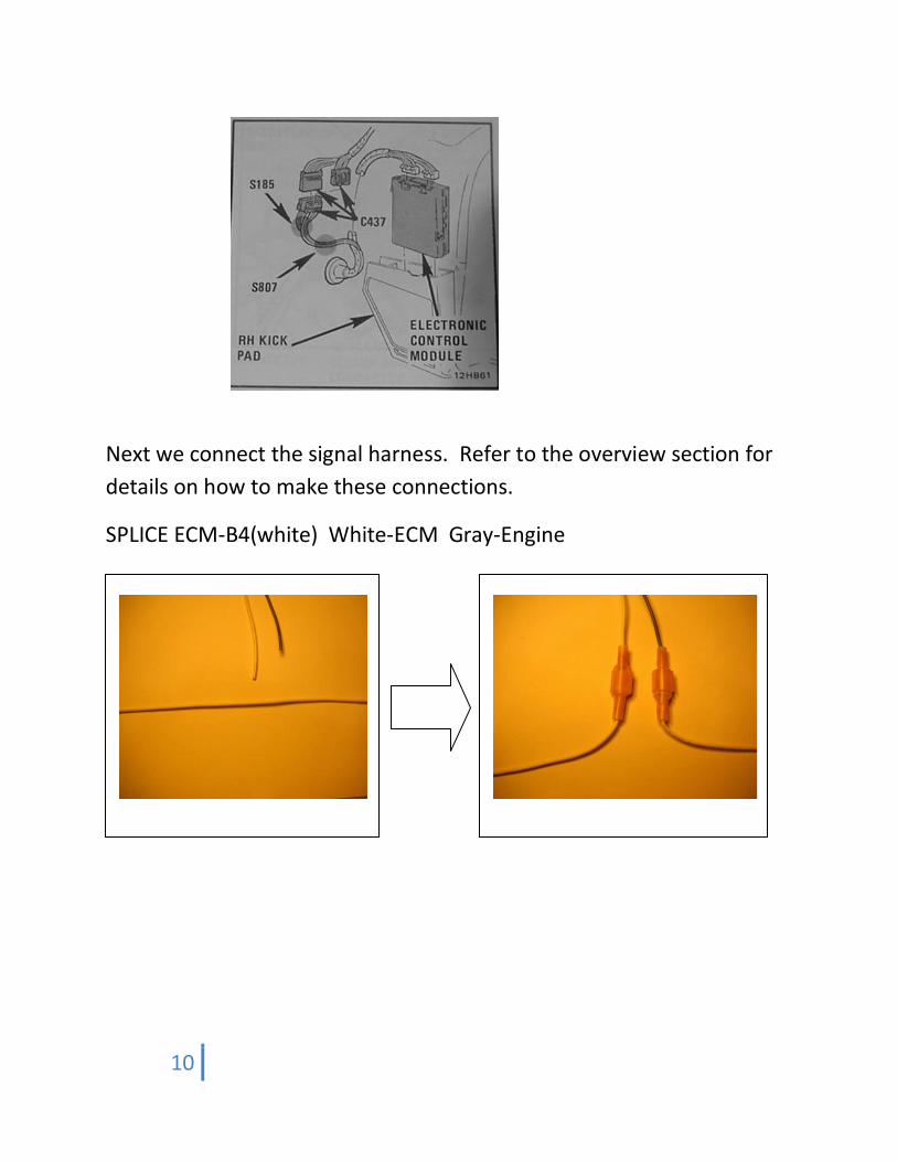
Next we connect the signal harness. Refer to the overview section for
details on how to make these connections.
SPLICE ECM-B4(white) White-ECM Gray-Engine

11
Refer to the ECM connector diagram below. The ECM is located in the
passenger side kick panel.
The rest of the wires in the “signal” harness will not be connected,
wrap them up and secure them out of the way.
The gray and brown wires in the Power harness are used for triggering
the unit. There are many ways to configure these, depending on the
configuration of the vehicle. The Brown wire activates the 2-step rev-
limiting feature, and the Gray wire activates the timing retard.
Connecting these wires to a voltage source activates them, they are
not activated by a ‘ground’. The inputs have spike suppression built in,
but it is not recommended to connect them directly to a trans-brake
solenoid. A relay is recommended. A suggested connection scheme is
shown below. Visit www.2step.bailey-eng.com for more information.

12
ECLIPSE / TALON / LASER (DSM)
TBD.
3000GT / STEALTH
Mount the unit in a suitable location, connect both harnesses (signal
and power) to the unit. The Power harness has 5 wires, the red+pink
wires must be connected at the fusebox. Pull the black, gray, and
brown wires out of the plastic tubing for half the length of the harness.
Run the Power harness under the dashboard to the fusebox that is near
the driver’s left foot, under the dash. Be sure to route it such that it
does not interfere with the operation of the pedals or steering. The
Power harness has a fuse-box adapter installed on the end of the red
and pink wires. The fusebox has an empty slot, this is fuse number 8.
Insert a 10A fuse into the open slot on the fuse-box adapter and plug
the fuse-box adapter into the empty slot at fuse number 8 with the
wires extending up.

13
Run the black wire to the ECU, cut it to length, strip it, and install a ring
terminal on the end using a strong crimp. Make sure the crimp is solid,
as many cheap crimpers cannot generate the necessary force to ensure
a good crimp. Tug on the crimped terminal firmly and ensure the wire
does not move. Secure the ground wire to one of the screws holding
on the side of the center console under the dash. The best ground is a
true engine ground, the center console metal structure is a good
compromise. Next we connect the signal harness. Refer to the
overview section for details on how to make these connections.

14
SPLICE ECM-B4(white) White-ECM Gray-Engine
SPLICE ECM-B4(white) xxxxx-ECM xxxx-Engine
SPLICE ECM-B4(white) xxxx-ECM xxxx-Engine
SPLICE ECM-B4(white) xxxx-ECM xxxx-Engine
TAP ECM-C13(blue) Blue
Refer to the connector diagram below.
The rest of the wires in the “signal” harness will not be connected,
wrap them up and secure them out of the way.
another diagram

15
The gray and brown wires in the Power harness are used for triggering
the unit. A suggested connection scheme is shown below.
TOYOTA SUPRA
MUSTANG V6
ADDITIONAL VEHICLES
INTERNAL ADJUSTMENTS AND SETTINGS
OVERVIEW
Inside the 2-Step control unit are 2 green LEDs labeled “Run” and
“Trig”. The Run LED lights whenever the engine is running. It will blink
whenever the Main RPM limit has activated and is controlling RPM.
Also the Run LED will blink whenever the DIP-Switch settings are
changed to verify the change was recognized.
The Trig LED lights whenever the Trigger inputs have activated the Trig
limit setting. This is somewhat different depending on the vehicle. This
LED will blink whenever the Trig RPM limit has activated and is
controlling RPM.
Triggering diagram for manual transmission vehicle showing
clutch switch and arming switch.

16
The unit has 3 “DIP-Switches” inside. 2 are used to set the Main and
Trig RPM settings. For these, each switch tab has an RPM value shown
next to it. For all switch tabs that are in the On position, add their
respective RPM values together to arrive at the setting for that switch.
For example, to set the Main RPM to 6500 RPM turn on the 4000,
2000, 400, and 100 switch tabs.
The third switch has 8 tabs, 5 are used for setting the “Mode” of the 2-
step unit which enables or controls various advanced features of the
unit. 3 tabs are used to set the “Configuration” of the 2-step unit to
match the unit to the type of vehicle that the unit is installed in.
Note that the switches themselves have numbers printed on them,
these should not be confused with the correct indicators printed above
the switches.
17
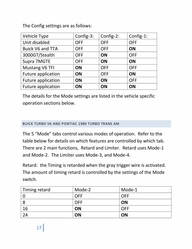
The Config settings are as follows:
Vehicle Type Config-3: Config-2: Config-1:
Unit disabled OFF OFF OFF Buick V6 and TTA OFF OFF ON
3000GT/Stealth OFF ON OFF Supra 7MGTE OFF ON ON
Mustang V6 TFI ON OFF OFF Future application ON OFF ON
Future application ON ON OFF Future application ON ON ON
The details for the Mode settings are listed in the vehicle specific
operation sections below.
BUICK TURBO V6 AND PONTIAC 1989 TURBO TRANS AM
The 5 “Mode” tabs control various modes of operation. Refer to the
table below for details on which features are controlled by which tab.
There are 2 main functions, Retard and Limiter. Retard uses Mode-1
and Mode-2. The Limiter uses Mode-3, and Mode-4.
Retard: the Timing is retarded when the gray trigger wire is activated.
The amount of timing retard is controlled by the settings of the Mode
switch.
Timing retard Mode-2 Mode-1 0 OFF OFF
8 OFF ON 16 ON OFF
24 ON ON
18
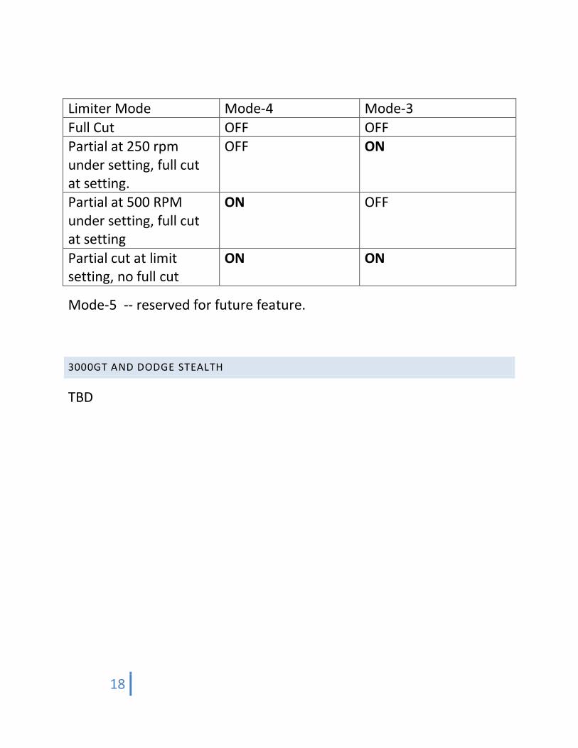
Limiter Mode Mode-4 Mode-3
Full Cut OFF OFF Partial at 250 rpm under setting, full cut at setting.
OFF ON
Partial at 500 RPM under setting, full cut at setting
ON OFF
Partial cut at limit setting, no full cut
ON ON
Mode-5 -- reserved for future feature.
3000GT AND DODGE STEALTH
TBD
19
TROUBLESHOOTING
No LEDs light up, engine does not start.
o Check for fuse installed in the fuse box adapter in the
Power Harness.Check that the ground wire is connected
to grounded metal.
Trig LED will not light.
o Check that the trigger input sources are voltage sources
and not grounds.
Run LED flashes when setting is changed.
o This is normal and confirms that the setting was received
by the unit.
Engine starts then stalls (Buick).
o Verify that the EST splice connections are not reversed.
ADDITIONAL FEATURES AND ADVANCED PROGRAMMING
Additional features are in development, check www.2step.bailey-
eng.com for details
SOFTWARE UPDATE
The unit can be updated (reflashed) by the user by connecting it to your
computer using a standard USB cable. This cable is not included with
the 2-step unit, but is available from the dealer where you purchased
the unit, or any computer, electronics, or appliance store. The unit
can be powered via the USB cable so it is not necessary to reflash the
unit in the vehicle.

20
The version of software in the unit can be verified by setting the config
switch tabs to all OFF. The Trig LED will then blink out the version
number. Zero is represented by a short flash, other digits by a series of
longer flashes. For example, 1.0.0 will appear as 1 long flash, pause,
short flash, pause, short flash. This sequence repeats indefinitely. Do
not run the engine in this mode.
The latest updates can be downloaded from www.2Step.bailey-
eng.com The unit does not need to be installed in a vehicle to perform
this update. To update the unit, follow the procedure below.
(additional help is available at the web site)
Download the update software from the website listed above.
The software will be in a ‘zip’ file which is treated as a
‘compressed folder’ by the later versions of Windows.
Save the zip file (compressed folder) onto the Windows desktop.
Open the zip file (compressed folder), inside you will find a folder
named “Reflash” click and drag this folder out of the compressed
folder and drop it on the desktop. Then delete the compressed
folder.
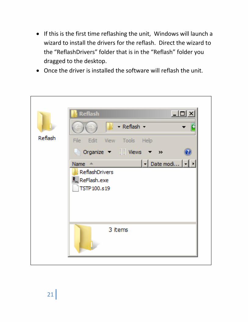
Double click the “Reflash” folder to open it, inside will be 2 files
and another folder named “ReflashDrivers”. The 2 files are
“Reflash.exe” and TSTPxxx.S19 (the software update, xxx is the
version)
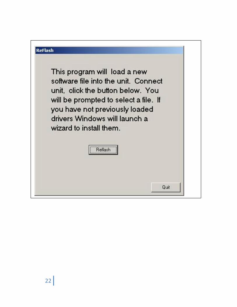
Double click the “Reflash” program, and a window will open as
shown.
Click the “Reflash” button, a file select window will open, select
the update “S19” file, and click Open.
21
If this is the first time reflashing the unit, Windows will launch a
wizard to install the drivers for the reflash. Direct the wizard to
the “ReflashDrivers” folder that is in the “Reflash” folder you
dragged to the desktop.
Once the driver is installed the software will reflash the unit.
22