balance control of robot and human-robot …lars.mec.ua.pt/public/lar...
TRANSCRIPT
.
978-1-4244-3960-7/09/ $25.00 2009 IEEE 68
HSI 2009 Catania, Italy, May 21-23, 2009
Abstract — This paper presents a haptic sensor foot
system for humanoid robot and an active tactile sensing technique to balance the humanoid robot with two legs for human and robot interaction task. The proposed sensors are implemented on two robotic foots. The sensor unit contains three thin sheets of force sensitive resistors. Those elements are arranged triangularly on the back of each foot. The research objective is to produce an artifact, which can be operated in a natural and intuitive manner by utilizing the haptic information to control a robot motion to keep the balance on the different contacted ground slopes with their both legs. As a possible application, we also attempted to let the robot avoid the falling down due to the external force by the unpredicted pushing action apply to the robot during human-robot interaction. In these applications, the informa- tion about the contacted ground floor or robot orientation is not required in advance.
Keywords — Tactile sensor, Haptic sensor, Ground floor recognition, Human-robot interactions, Robots.
I. INTRODUCTION
ECENTLY, computers are integrant in the parts of our life and embedded in various devices, objects, and
systems. Thus, the interactions between Human and Comp- uters have evolved toward interactions between Human and Systems. Since, human system interaction (HSI) has evolved, so it has the various technologies that enabled for
This work was supported in part by "Establishment of Consolidated
Research Institute for Advanced Science and Medical Care", Encouraging Development Strategic Research Centers Program, the Special Coordination Funds for Promoting Science and Technology, Ministry of Education, Culture, Sports, Science and Technology, Japan. This research was also supported (in part) by the research grant of Support Center for Advanced Telecommunications Technology Research (SCAT), Project for Strategic Development of Advanced Robotics Elemental Technologies (NEDO: 06002090), the Grant-in-Aid for the WABOT-HOUSE Project by Gifu Prefecture and the 21st Century Center of Excellence Program, "The innovative research on symbiosis technologies for human and robots in the elderly dominated society" Waseda University, The research grant of foundation for the Fusion of Sciences and Technology 2009, the Global-COE Program, "Global Robot Academia" Waseda University, and the Research Fellowships of the Japan Society for the promotion of Science for Young Scientists (JSPS).
Kitti Suwanratchatamanee and Shuji Hashimoto are with Graduate School of Advanced Science and Engineering, Waseda University, 55N-4F-10A, 3-4-1 Okubo, Shinjuku-ku, Tokyo, 169-8555, Japan. (e-mail: [email protected]; [email protected]).
Mitsuharu Matsumoto is with Education and Research Center for Frontier Science, University of Electro-Communications, 1-5-1, Chofugao ka, Chofu-shi, Tokyo, 182-8585, Japan. (e-mail: mitsuharu.matsumoto@ ieee.org).
this interaction. Implementations, on the other hand, for multimodal interaction between human and robot are not completed to create a new generation of robotics. When we
Balance Control of Robot and Human-Robot Interaction with Haptic Sensing Foots
Kitti Suwanratchatamanee†, Graduate Student Member, IEEE, Mitsuharu Matsumoto‡, Member, IEEE, and Shuji Hashimoto†, Member, IEEE †Graduate School of Advanced Science and Engineering, Waseda University,
‡ Education and Research Center for Frontier Science, University of Electro-Communications
R
Computer (PC)
COM Port
Robot Control Command
Left-Foot Signals (LEDs / Sensors )
Sensor Interface Module
Control/Drive
(Humanoid Robot)
Servo Control Signals (17 DOF)
Humanoid Robot
Sensor Units
Ground Floor
Unit
Right-Foot Signalas (LEDs / Sensors )
L
R
Wireless(Radio Signal)
Drive Unit(Robotic Arm)
Robotic ArmMitsubitshi RV-M1
Interface Unit (L Foot)
Interface Unit (R Foot)
Transmitter Unit
Main CPU Interface Unit
Robot Control Command
Servo Control Signals (5 DOF)
Tx
Rx
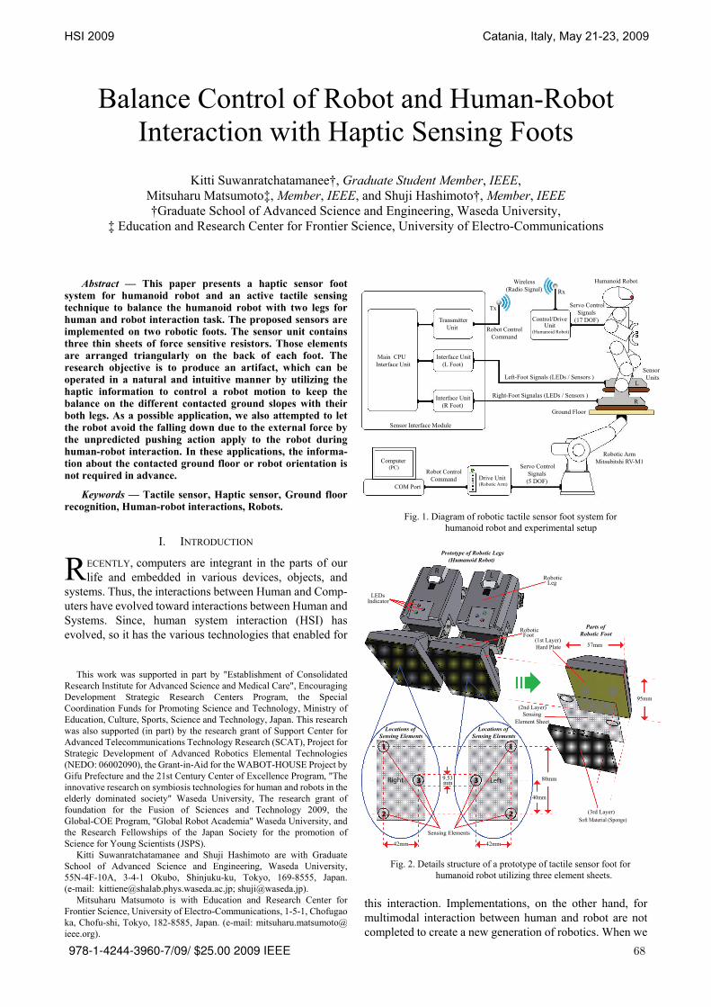
Fig. 1. Diagram of robotic tactile sensor foot system for
humanoid robot and experimental setup
Sensing Element Sheet
Hard Plate
LEDs Indicator
Leg
Soft Material (Sponge)
Sensing Elements
57mm
95mm
9.53
42mm
80mm
40mm
Locations ofSensing Elements
Parts of Robotic Foot
1
2
3
Foot
Prototype of Robotic Legs (Humanoid Robot)
mm
Locations ofSensing Elements
Right Left
R L
1
2
3
42mm
(1st Layer)
(2nd Layer)
(3rd Layer)
Robotic
Robotic
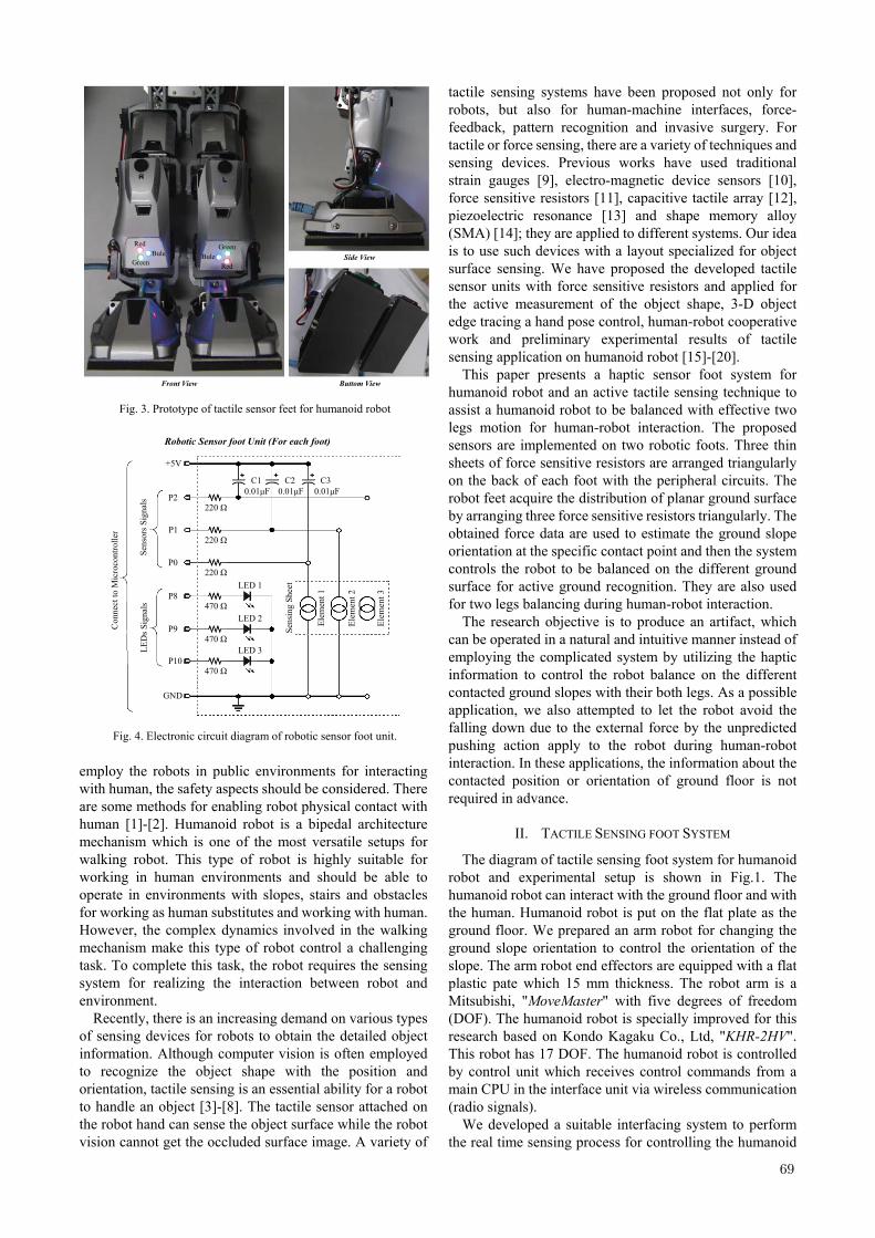
Fig. 2. Details structure of a prototype of tactile sensor foot for humanoid robot utilizing three element sheets.
.
69
employ the robots in public environments for interacting with human, the safety aspects should be considered. There are some methods for enabling robot physical contact with human [1]-[2]. Humanoid robot is a bipedal architecture mechanism which is one of the most versatile setups for walking robot. This type of robot is highly suitable for working in human environments and should be able to operate in environments with slopes, stairs and obstacles for working as human substitutes and working with human. However, the complex dynamics involved in the walking mechanism make this type of robot control a challenging task. To complete this task, the robot requires the sensing system for realizing the interaction between robot and environment.
Recently, there is an increasing demand on various types of sensing devices for robots to obtain the detailed object information. Although computer vision is often employed to recognize the object shape with the position and orientation, tactile sensing is an essential ability for a robot to handle an object [3]-[8]. The tactile sensor attached on the robot hand can sense the object surface while the robot vision cannot get the occluded surface image. A variety of
tactile sensing systems have been proposed not only for robots, but also for human-machine interfaces, force- feedback, pattern recognition and invasive surgery. For tactile or force sensing, there are a variety of techniques and sensing devices. Previous works have used traditional strain gauges [9], electro-magnetic device sensors [10], force sensitive resistors [11], capacitive tactile array [12], piezoelectric resonance [13] and shape memory alloy (SMA) [14]; they are applied to different systems. Our idea is to use such devices with a layout specialized for object surface sensing. We have proposed the developed tactile sensor units with force sensitive resistors and applied for the active measurement of the object shape, 3-D object edge tracing a hand pose control, human-robot cooperative work and preliminary experimental results of tactile sensing application on humanoid robot [15]-[20].
This paper presents a haptic sensor foot system for humanoid robot and an active tactile sensing technique to assist a humanoid robot to be balanced with effective two legs motion for human-robot interaction. The proposed sensors are implemented on two robotic foots. Three thin sheets of force sensitive resistors are arranged triangularly on the back of each foot with the peripheral circuits. The robot feet acquire the distribution of planar ground surface by arranging three force sensitive resistors triangularly. The obtained force data are used to estimate the ground slope orientation at the specific contact point and then the system controls the robot to be balanced on the different ground surface for active ground recognition. They are also used for two legs balancing during human-robot interaction.
The research objective is to produce an artifact, which can be operated in a natural and intuitive manner instead of employing the complicated system by utilizing the haptic information to control the robot balance on the different contacted ground slopes with their both legs. As a possible application, we also attempted to let the robot avoid the falling down due to the external force by the unpredicted pushing action apply to the robot during human-robot interaction. In these applications, the information about the contacted position or orientation of ground floor is not required in advance.
II. TACTILE SENSING FOOT SYSTEM
The diagram of tactile sensing foot system for humanoid robot and experimental setup is shown in Fig.1. The humanoid robot can interact with the ground floor and with the human. Humanoid robot is put on the flat plate as the ground floor. We prepared an arm robot for changing the ground slope orientation to control the orientation of the slope. The arm robot end effectors are equipped with a flat plastic pate which 15 mm thickness. The robot arm is a Mitsubishi, "MoveMaster" with five degrees of freedom (DOF). The humanoid robot is specially improved for this research based on Kondo Kagaku Co., Ltd, "KHR-2HV". This robot has 17 DOF. The humanoid robot is controlled by control unit which receives control commands from a main CPU in the interface unit via wireless communication (radio signals).
We developed a suitable interfacing system to perform the real time sensing process for controlling the humanoid
Side View
Buttom ViewFront View
RedBule
Green RedBule
Green
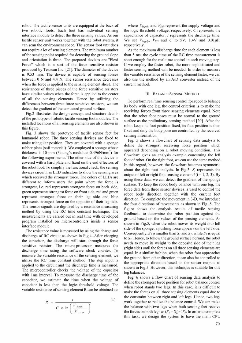
Fig. 3. Prototype of tactile sensor feet for humanoid robot
Con
nect
to M
icro
cont
rolle
r
+5V
P2
P1
P0
P8
P9
P10
GND
220 Ω
220 Ω
220 Ω
470 Ω
470 Ω
470 Ω
LED 1
LED 3
LED 2
C10.01μF
C20.01μF
C30.01μF
Elem
ent 1
Elem
ent 2
Elem
ent 3
Sens
ing
Shee
t
Robotic Sensor foot Unit (For each foot)
LED
s Sig
nals
Sens
ors S
igna
ls
Fig. 4. Electronic circuit diagram of robotic sensor foot unit.
.
70
robot. The tactile sensor units are equipped at the back of two robotic foots. Each foot has individual sensing interface module to detect the three sensing values. As our tactile sensor unit works together with the robot system, it can scan the environment space. The sensor foot unit does not require a lot of sensing elements. The minimum number of the sensing point required for detecting the ground slope and orientation is three. The prepared devices are "Flexi Force" which is a sort of the force sensitive resistor produced by Tekscan Inc. [21]. The diameter of the device is 9.53 mm. The device is capable of sensing forces between 0 N and 4.4 N. The sensor resistance decreases when the force is applied to the sensing element sheet. The resistances of three pieces of the force sensitive resistors have similar values when the force is applied to the center of all the sensing elements. Hence by utilizing the differences between three force sensitive resistors, we can detect the gradient of the contacted ground surface.
Fig.2 illustrates the design concept and structure details of the prototype of robotic tactile sensing foot modules. The installed locations of all sensing elements are also shown in this figure.
Fig. 3 shows the prototype of tactile sensor feet for humanoid robot. The three sensing devices are fixed to make triangular position. They are covered with a sponge rubber plate (soft material). We employed a sponge whose thickness is 10 mm (Young’s modulus: 0.496N/mm2) for the following experiments. The other side of the device is covered with a hard plate and fixed on the end effectors of the robot foot. To simplify the functional check, the sensing devices circuit has LED indicators to show the sensing area which received the strongest force. The colors of LEDs are different to inform users the point where the force is strongest, i.e. red represents strongest force on back side, green represents strongest force on front side, red and green represent strongest force on their leg side and blue represents strongest force on the opposite of their leg side. The sensor signals are digitized by a resistance measuring method by using the RC time constant technique. The measurements are carried out in real time with developed program installed on microcontrollers inside a sensor interface module.
The resistance value is measured by using the charge and discharge of RC circuit as shown in Fig.4. After charging the capacitor, the discharge will start through the force sensitive resistor. The micro-processor measures the discharge time using the software clock counter. To measure the variable resistance of the sensing element, we utilize the RC time constant method. The step input is applied to the circuit and the discharge time is measured. The microcontroller checks the voltage of the capacitor with 1ms interval. To measure the discharge time of the capacitor, we estimate the time when the voltage of capacitor is less than the logic threshold voltage. The variable resistance of sensing element R can be obtained as:
ln
/⎟⎟⎠
⎞⎜⎜⎝
⎛×
=
OI
Supply
VV
C
tR (1)
where VSupply and VI/O represent the supply voltage and the logic threshold voltage, respectively. C represents the capacitance of capacitor. t represents the discharge time. We set VSupply, VI/O and C to 5V, 1.4V and 0.01μF, respectively.
As the maximum discharge time for each element is less than 5 ms, the cycle time of the RC time measurement is short enough for the real time control in each moving step. If we employ the faster robot, the more sophisticated and faster sensing method will be needed. In order to measure the variable resistance of the sensing element faster, we can also use the method by an A/D converter instead of the current method.
III. BALANCE SENSING METHOD
To perform real time sensing control for robot to balance its body with one leg, the control criterion is to make the receiving forces from three sensing elements equal. Note that the robot foot poses must be normal to the ground surface as the preliminary sensing method [20]. After the robot keeps its foot position fixed, its foot position is then fixed and only the body pose are controlled by the received sensing information.
Fig. 5 shows a flowchart of sensing data analysis to define the strongest receiving force position which appeared depending on a robot moving condition. This flowchart gives an analysis example concerning the left foot of robot. On the right foot, we can use the same method. In this regard, however, the flowchart becomes symmetric about the right foot analysis. In Fig.5, Si represents the output of left or right foot sensing element i (i = 1, 2, 3). By using these data, we can detect the gradient of the sponge surface. To keep the robot body balance with one leg, the force data from three sensor devices is used to control the robot body direction together with the current foot direction. To complete the movement in 3-D, we introduce the four directions of movements as shown in Fig. 5. The figure shows the analysis results of tactile sensing feedbacks to determine the robot position against the ground based on the values of the sensing elements. As shown in Fig.5, when the robot moves its weight into left side of the sponge, a pushing force appears on the left side. Consequently, S3 is smaller than S1 and S2, while S1 is equal to S2. Hence, to follow the ground surface normal, the robot needs to move its weight to the opposite side of their leg (right side) until the forces on all three sensing elements are equal. In a similar fashion, when the robot foot approaches the ground from other direction, it can also be controlled to the appropriate direction based on the sensor outputs as shown in Fig.5. However, this technique is suitable for one leg balances.
Fig. 6 shows a flow chart of sensing data analysis to define the strongest force position for robot balance control when robot stands two legs. In this case, it is difficult to make the forces on all three sensing elements equal due to the constraint between right and left legs. Hence, two legs work together to realize the balance control. We can make the balance with two legs when both sensing feet receive the forces on both legs as (S1 = S2) < S3. In order to complete this task, we design the system to have the main CPU
.
71
interface unit for collecting information from two sensing feet and determine the robot position from the collected data. After that, the unit will decide the appropriate control motion based on the sensor outputs as shown in Fig.6.
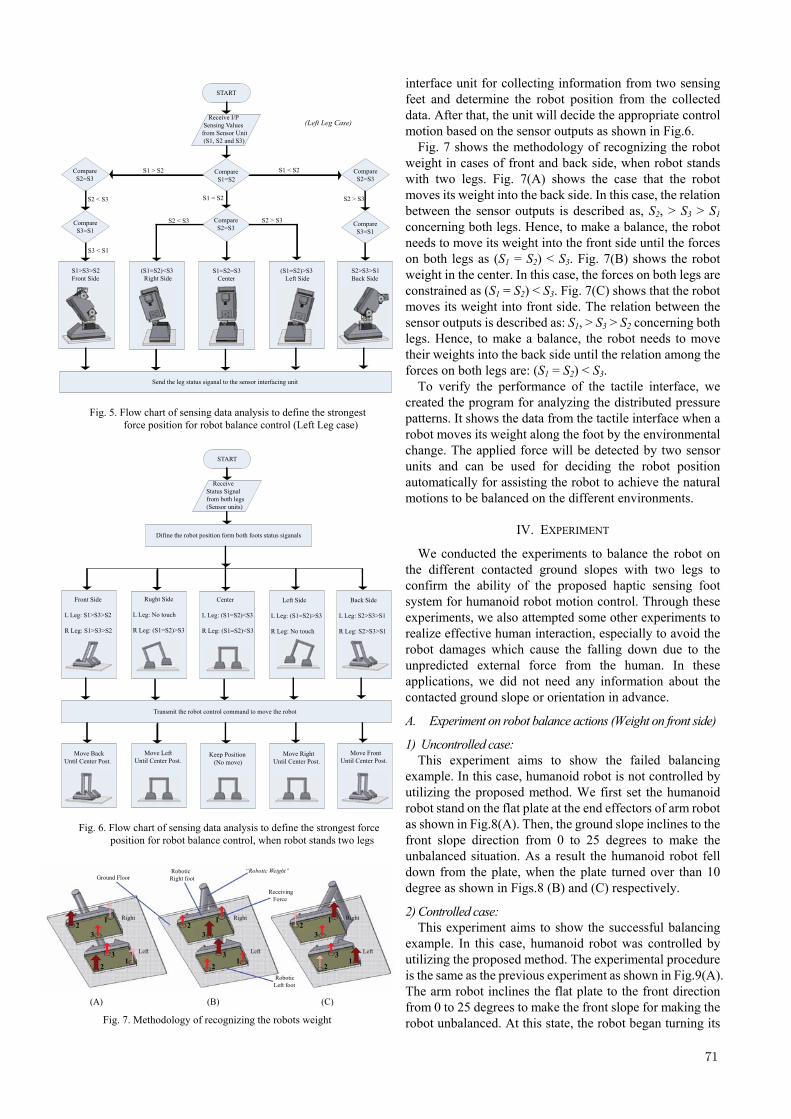
Fig. 7 shows the methodology of recognizing the robot weight in cases of front and back side, when robot stands with two legs. Fig. 7(A) shows the case that the robot moves its weight into the back side. In this case, the relation between the sensor outputs is described as, S2, > S3 > S1 concerning both legs. Hence, to make a balance, the robot needs to move its weight into the front side until the forces on both legs as (S1 = S2) < S3. Fig. 7(B) shows the robot weight in the center. In this case, the forces on both legs are constrained as (S1 = S2) < S3. Fig. 7(C) shows that the robot moves its weight into front side. The relation between the sensor outputs is described as: S1, > S3 > S2 concerning both legs. Hence, to make a balance, the robot needs to move their weights into the back side until the relation among the forces on both legs are: (S1 = S2) < S3.
To verify the performance of the tactile interface, we created the program for analyzing the distributed pressure patterns. It shows the data from the tactile interface when a robot moves its weight along the foot by the environmental change. The applied force will be detected by two sensor units and can be used for deciding the robot position automatically for assisting the robot to achieve the natural motions to be balanced on the different environments.
IV. EXPERIMENT
We conducted the experiments to balance the robot on the different contacted ground slopes with two legs to confirm the ability of the proposed haptic sensing foot system for humanoid robot motion control. Through these experiments, we also attempted some other experiments to realize effective human interaction, especially to avoid the robot damages which cause the falling down due to the unpredicted external force from the human. In these applications, we did not need any information about the contacted ground slope or orientation in advance.
A. Experiment on robot balance actions (Weight on front side)
1) Uncontrolled case: This experiment aims to show the failed balancing
example. In this case, humanoid robot is not controlled by utilizing the proposed method. We first set the humanoid robot stand on the flat plate at the end effectors of arm robot as shown in Fig.8(A). Then, the ground slope inclines to the front slope direction from 0 to 25 degrees to make the unbalanced situation. As a result the humanoid robot fell down from the plate, when the plate turned over than 10 degree as shown in Figs.8 (B) and (C) respectively.
2) Controlled case: This experiment aims to show the successful balancing
example. In this case, humanoid robot was controlled by utilizing the proposed method. The experimental procedure is the same as the previous experiment as shown in Fig.9(A). The arm robot inclines the flat plate to the front direction from 0 to 25 degrees to make the front slope for making the robot unbalanced. At this state, the robot began turning its
Receive I/P Sensing Valuesfrom Sensor Unit (S1, S2 and S3)
START
Compare S1=S2
S1 < S2 Compare S2=S3
S2 > S3
Compare S3=S1
S1 > S2
S1 = S2
Compare S2=S3
S2 > S3S2 < S3
Compare S2=S3
Compare S3=S1
S2 < S3
S3 < S1
S1>S3>S2 Front Side
(S1=S2)<S3 Right Side
S1=S2=S3 Center
Send the leg status siganal to the sensor interfacing unit
(S1=S2)>S3 Left Side
S2>S3>S1 Back Side
(Left Leg Case)
Fig. 5. Flow chart of sensing data analysis to define the strongest
force position for robot balance control (Left Leg case)
Receive Status Signal from both legs (Sensor units)
START
Left Side
L Leg: (S1=S2)>S3
R Leg: No touch
Rught Side
L Leg: No touch
R Leg: (S1=S2)>S3
Center
L Leg: (S1=S2)<S3
R Leg: (S1=S2)<S3
Back Side
L Leg: S2>S3>S1
R Leg: S2>S3>S1
Front Side
L Leg: S1>S3>S2
R Leg: S1>S3>S2
Difine the robot position form both foots status siganals
Keep Position (No move)
Move BackUntil Center Post.
Move Left Until Center Post.
Move RightUntil Center Post.
Move FrontUntil Center Post.
Transmit the robot control command to move the robot
Fig. 6. Flow chart of sensing data analysis to define the strongest force
position for robot balance control, when robot stands two legs
Robotic Right foot
Robotic Left foot
“Robotic Weight” Ground Floor
Receiving Force
2
2
3
3
1
1
2
2
3
3
1
1
2
2
3
3
1
1
Right
Left
Right
Left
Right
Left
(A) (B) (C)
Fig. 7. Methodology of recognizing the robots weight
.
72
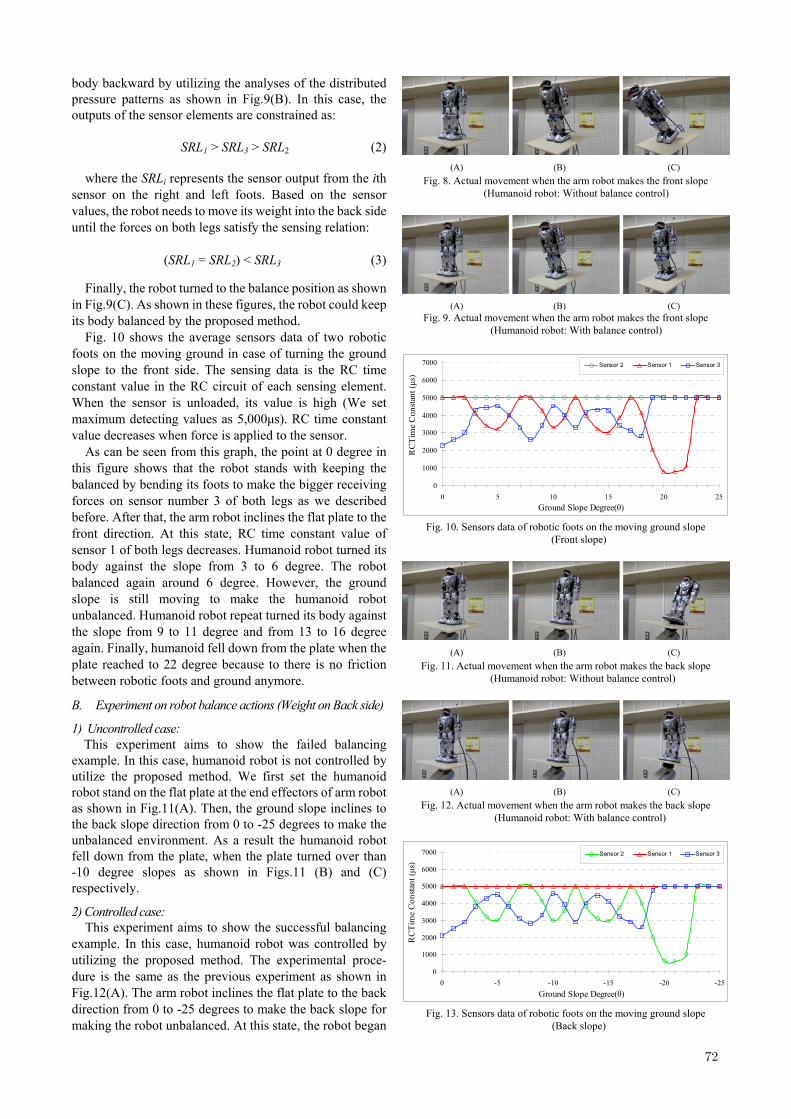
body backward by utilizing the analyses of the distributed pressure patterns as shown in Fig.9(B). In this case, the outputs of the sensor elements are constrained as:
SRL1 > SRL3 > SRL2 (2)
where the SRLi represents the sensor output from the ith
sensor on the right and left foots. Based on the sensor values, the robot needs to move its weight into the back side until the forces on both legs satisfy the sensing relation:
(SRL1 = SRL2) < SRL3 (3)
Finally, the robot turned to the balance position as shown
in Fig.9(C). As shown in these figures, the robot could keep its body balanced by the proposed method.
Fig. 10 shows the average sensors data of two robotic foots on the moving ground in case of turning the ground slope to the front side. The sensing data is the RC time constant value in the RC circuit of each sensing element. When the sensor is unloaded, its value is high (We set maximum detecting values as 5,000μs). RC time constant value decreases when force is applied to the sensor.
As can be seen from this graph, the point at 0 degree in this figure shows that the robot stands with keeping the balanced by bending its foots to make the bigger receiving forces on sensor number 3 of both legs as we described before. After that, the arm robot inclines the flat plate to the front direction. At this state, RC time constant value of sensor 1 of both legs decreases. Humanoid robot turned its body against the slope from 3 to 6 degree. The robot balanced again around 6 degree. However, the ground slope is still moving to make the humanoid robot unbalanced. Humanoid robot repeat turned its body against the slope from 9 to 11 degree and from 13 to 16 degree again. Finally, humanoid fell down from the plate when the plate reached to 22 degree because to there is no friction between robotic foots and ground anymore.
B. Experiment on robot balance actions (Weight on Back side)
1) Uncontrolled case: This experiment aims to show the failed balancing
example. In this case, humanoid robot is not controlled by utilize the proposed method. We first set the humanoid robot stand on the flat plate at the end effectors of arm robot as shown in Fig.11(A). Then, the ground slope inclines to the back slope direction from 0 to -25 degrees to make the unbalanced environment. As a result the humanoid robot fell down from the plate, when the plate turned over than -10 degree slopes as shown in Figs.11 (B) and (C) respectively.
2) Controlled case: This experiment aims to show the successful balancing
example. In this case, humanoid robot was controlled by utilizing the proposed method. The experimental proce- dure is the same as the previous experiment as shown in Fig.12(A). The arm robot inclines the flat plate to the back direction from 0 to -25 degrees to make the back slope for making the robot unbalanced. At this state, the robot began
(A) (B) (C)
Fig. 8. Actual movement when the arm robot makes the front slope (Humanoid robot: Without balance control)
(A) (B) (C) Fig. 9. Actual movement when the arm robot makes the front slope
(Humanoid robot: With balance control)
0
1000
2000
3000
4000
5000
6000
7000
0 5 10 15 20 25Ground Slope Degree(θ)
RC
Tim
e C
onsta
nt (μ
s)
Sensor 2 Sensor 1 Sensor 3
Fig. 10. Sensors data of robotic foots on the moving ground slope (Front slope)
(A) (B) (C)
Fig. 11. Actual movement when the arm robot makes the back slope (Humanoid robot: Without balance control)
(A) (B) (C)
Fig. 12. Actual movement when the arm robot makes the back slope (Humanoid robot: With balance control)
0
1000
2000
3000
4000
5000
6000
7000
0 -5 -10 -15 -20 -25Ground Slope Degree(θ)
RC
Tim
e C
onsta
nt (μ
s)
Sensor 2 Sensor 1 Sensor 3
Fig. 13. Sensors data of robotic foots on the moving ground slope (Back slope)
.
73
turning its body forward by utilizing the analyses of the distributed pressure patterns as shown in Fig.12(B). In this case, the outputs of the sensor elements are constrained as:
SRL2 > SRL3 > SRL1 (4) Based on the sensor values, the robot needs to move its
weight to the front side until the relation among the forces on both legs are satisfied with Eq(3). Finally, the robot turned to the balance position as shown in Fig.12(C). As shown in these figures, the robot also could keep its body based on the balance control.
Fig. 13 shows the average sensors data of two robotic foots on the moving ground slope in case of turning the ground slope to the back side. As can be seen from this graph, the point at 0 degree in this figure shows that the robot stands with keeping the balance by bending its foots to make the bigger receiving forces on sensor number 3 of both legs as we described before. After the arm robot inclines the flat plate to the back direction. At this state, RC time constant value of sensor 2 of both legs decreases. Humanoid robot turned its body against the slope from 3 to 6 degree. The robot balanced again around 6 degree. However, the ground slope is still moving to make the humanoid robot unbalanced. Humanoid robot repeat turned its body against the slope from 9 to 11 degree and from 13 to 16 degree again. Finally, humanoid fell down from the plate when the plate reached to -22 degree because there is
no friction between robotic foots and ground anymore.
C. Interaction between human and robot In this section, we aim to realize the successful balancing
example in human-robot interaction. The haptic feedback to human is appeared after touch the robot shoulder. The first feedback is the LED will display that which side of the robot body has detected the pushing force. Then robot moves its leg on another side to support its body against the pushing force even human push harder. Thus the humanoid robot can keep its balance not only against human pushing but also to avoid the damages caused by the falling down.
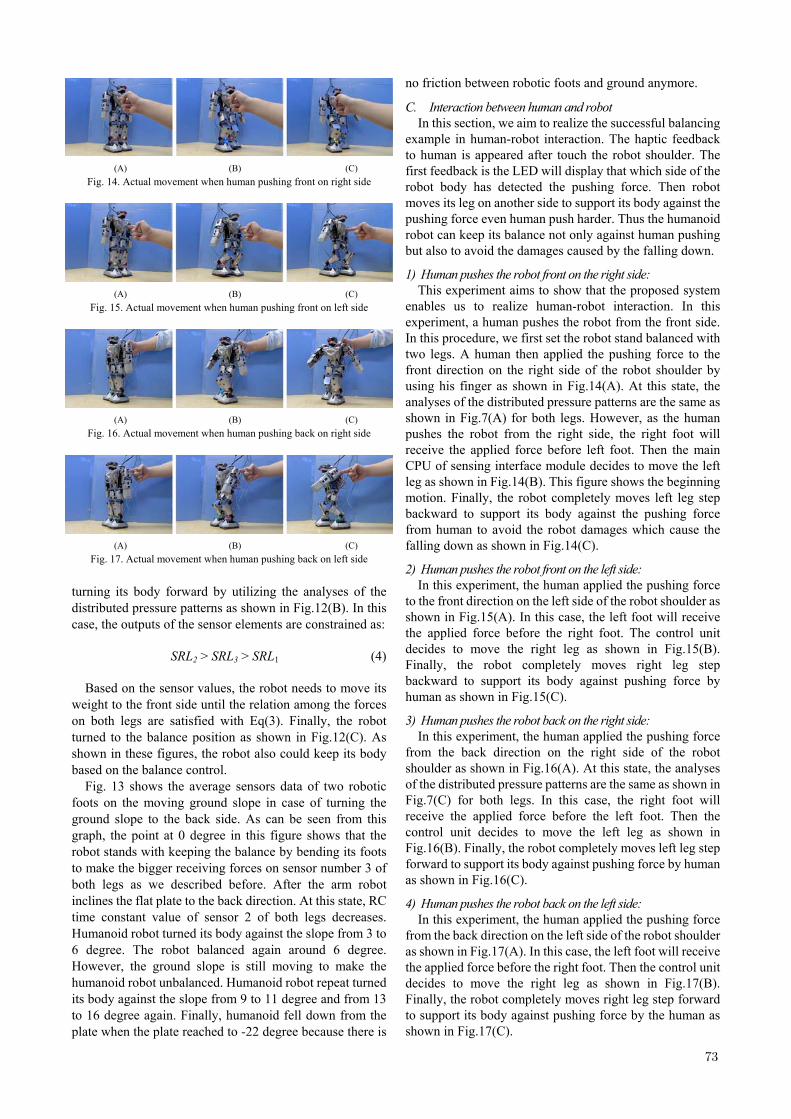
1) Human pushes the robot front on the right side: This experiment aims to show that the proposed system
enables us to realize human-robot interaction. In this experiment, a human pushes the robot from the front side. In this procedure, we first set the robot stand balanced with two legs. A human then applied the pushing force to the front direction on the right side of the robot shoulder by using his finger as shown in Fig.14(A). At this state, the analyses of the distributed pressure patterns are the same as shown in Fig.7(A) for both legs. However, as the human pushes the robot from the right side, the right foot will receive the applied force before left foot. Then the main CPU of sensing interface module decides to move the left leg as shown in Fig.14(B). This figure shows the beginning motion. Finally, the robot completely moves left leg step backward to support its body against the pushing force from human to avoid the robot damages which cause the falling down as shown in Fig.14(C).
2) Human pushes the robot front on the left side: In this experiment, the human applied the pushing force
to the front direction on the left side of the robot shoulder as shown in Fig.15(A). In this case, the left foot will receive the applied force before the right foot. The control unit decides to move the right leg as shown in Fig.15(B). Finally, the robot completely moves right leg step backward to support its body against pushing force by human as shown in Fig.15(C).
3) Human pushes the robot back on the right side: In this experiment, the human applied the pushing force
from the back direction on the right side of the robot shoulder as shown in Fig.16(A). At this state, the analyses of the distributed pressure patterns are the same as shown in Fig.7(C) for both legs. In this case, the right foot will receive the applied force before the left foot. Then the control unit decides to move the left leg as shown in Fig.16(B). Finally, the robot completely moves left leg step forward to support its body against pushing force by human as shown in Fig.16(C).
4) Human pushes the robot back on the left side: In this experiment, the human applied the pushing force
from the back direction on the left side of the robot shoulder as shown in Fig.17(A). In this case, the left foot will receive the applied force before the right foot. Then the control unit decides to move the right leg as shown in Fig.17(B). Finally, the robot completely moves right leg step forward to support its body against pushing force by the human as shown in Fig.17(C).
(A) (B) (C)
Fig. 14. Actual movement when human pushing front on right side
(A) (B) (C)
Fig. 15. Actual movement when human pushing front on left side
(A) (B) (C)
Fig. 16. Actual movement when human pushing back on right side
(A) (B) (C)
Fig. 17. Actual movement when human pushing back on left side
.
74
V. CONCLUSION AND FUTURE WORKS
In this paper, we presented a haptic sensing foot system for humanoid robot and a force sensing technique in human-robot interactions. Sensor units are implemented on each robotic foots. The obtained force data is used to estimate the ground slope orientation and to move the robot keeping the balance on different ground slopes. As a result, we succeeded in balancing the robot automatically with two legs on the various ground slopes such as, flat level, front and back slopes. The maximum angle that can be detected is 22 degree while the minimum angle that can be detected is 3 degree in both front and back slope situations. We also succeeded in realizing the human-robot interaction when human pushes the robot from the various positions. Throughout the experiments, the robot could recognize the position of external forces direction and make a motion to support its body against pushing force by human and contacted ground floor to avoid the robot damages cause by the falling down. In these applications, we need no information about the contacted ground slope or orientation in advance.
For future works, we would like to utilize the proposed tactile sensor technique to control the robotic foot pose position, motion and balance control. We also would like to implement our method to keep the dynamic balance during the walking motion in unstructured environment to make human-robot interaction tasks more practical and flexible.
REFERENCES [1] B. Jensen, N. Tomatis, L. Mayor, A. Drygajlo and R. Siegwart,
“Robots Meet Humans—Interaction in Public Spaces”, IEEE Trans. on Industrial Electronics, Vol. 52, No. 6, pp.1530-1546, 2005.
[2] H. Iwata and S. Sugano, “Human–Robot-Contact-State Identification Based on Tactile Recognition”, IEEE Trans. on Industrial Electronics, Vol. 52, No. 6, pp.1468-1477, 2005.
[3] M. Rucci and P. Dario, “Active exploration procedures in robotic tactile perception,” Intelligent Robotic Systems, pp.20-24, 1993.
[4] P. Dario, A. Sabatini, B. Allotta, M. Bergamasco and G. Buttazzo, “A fingertip sensor with proximity, tactile and force sensing capabilities,” Proc. of IEEE Int’l Workshop on Intelligent Robots and Systems, pp.883-889, 1990.
[5] H. Maekawa, K. Tanie, and K. Komoriya, “Tactile Sensor Based Grasp and Manipulation of an Object by a Multifingered Hand,” Video Proc. of IEEE Int. Conf. on Robotics and Automation, 1996.
[6] J. Jockusch, J. Walter and H. Ritter, “A Tactile Sensor System for a Three-Fingered Robot Manipulator,” Proc. of IEEE Int’l. Conf. on Robotics and Automation, pp.3080-3086, 1997.
[7] H.-Y. Yoa, V. Hayward and R.E. Ellis, “A Tactile Magnification Instrument for Minimally Invasive Surgery”, Proc. of the 7th Int’l. Conf. of Medical Image Computing and Computer-Assisted Intervention, pp.89-96, 2004.
[8] M. E. Tremblay and M. R. Cutkosky, “Estimation friction using incipient slip sensing during a manipulation task”, Proc. of IEEE Int’l Conf on Robotics and Automation, pp.429-434, 1993.
[9] R.Hikiji and S.Hashimoto, “Hand-Shaped Force Interface for Human-Cooperative Mobile Robot,” Proc. of Int’l Workshop on Haptic Human-Computer Interaction, pp.113-118, 2000.
[10] T. Maeno and T. Kawamura, “Geometry Design of an Elastic Finger-Shaped Sensor for Estimating Friction Coefficient by Pressing an object,” Proc. of the 2003 IEEE International Conf. on Robotics & Automation, pp.1533-1538, 2003.
[11] R. Kikuuwe and T. Yoshikawa, “Recognizing Surface Properties using Impedance Perception”, Proc. of the 2003 IEEE International Conf. on Robotics & Automation, pp.1539-1544, 2003.
[12] Franco Castelli, “An Integrated Tactile-Thermal Robot Sensor with Capacitive Tactile Array”, IEEE Trans. on Industry Application, Vol. 38, No. 1, pp.85-90, 2002.
[13] G.Murali Krishna and K.Rajanna, “Tactile Sensor Based on Piezoelectric Resonance”, IEEE Sensors Journal, Vol. 4, No. 5, pp.691-697, 2004.
[14] T. Matsunaga, K. Totsu, M. Esashi and Y.Haga, “Tactile Display for 2-D and 3-D Shape Expression Using SMA Micro Actuators”, Proc. of IEEE Annual Int’l. Conf. on Microtechnologies in Medicine and Biology, pp.88-91, 2005
[15] K.Suwanratchatamanee, M.Matsumoto, R.Saegusa and S.Hashimoto “A Simple Tactile Sensor System for Robot Manipulator and Object Edge Shape Recognition”, Proc. of the 33rd IEEE Annual Int’l. Conf. of Industrial Electronics Society, pp.245-250, 2007.
[16] K. Suwanratchatamanee, M. Matsumoto and S. Hashimoto, “A Simple Robotic Tactile Sensor for Object Surface Sensing”, The Int’l Journal of Robotics Society Japan, Advanced Robotics, Vol.22, No.8, pp.867-892, 2008.
[17] K. Suwanratchatamanee, M. Matsumoto and S. Hashimoto, “A tactile sensor system for robot manipulator and continuous object edge tracking”, Proc. of the 7th France-Japan and 5th Europe-Asia Congress on Mechatronics, CD-ROM, 2008.
[18] K. Suwanratchatamanee, M. Matsumoto and S. Hashimoto, “Human-machine interaction through object using robot arm with tactile sensors” Proc. of the 17th IEEE Int’l. Symposium on Robot and Human Interactive Communication, pp.683-688, 2008.
[19] K. Suwanratchatamanee, M. Matsumoto and S. Hashimoto, “A Novel Tactile Sensor Torch System for Robot Manipulator and Object Edge Tracking”, Proc. of the 34th IEEE Annual Conference of Industrial Electronics Society, pp.2617-2622, 2008.
[20] K. Suwanratchatamanee, M. Matsumoto and S. Hashimoto, “A Simple Tactile Sensing Foot for Humanoid Robot and Active Ground Slope Recognition”, Proc. of the 5thIEEE Int’l. Conference on Mechatro- nics, (In Press), 2008.
[21] Texscan Inc., USA, “FlexiForce User Manual” www.tekscan.com.