balancing trenchless permitting requirements during hdd...
TRANSCRIPT
Paper MM-T4-03 - 1
TM1-T2-05
Balancing Trenchless Permitting Requirements
During HDD Design and Construction Christopher Price, Staheli Trenchless Consultants, Lynnwood, Washington Bob Neil, Denver Metro WRD, Denver, Colorado Mary Beth Sullivan, Carollo Engineers, Denver, Colorado Jim Kriss, Carollo Engineers, Denver, Colorado 1. ABSTRACT The Denver Metro Wastewater Reclamation District (MWRD) is installing a 10-inch pressure pipeline to carry potable water from the Robert W. Hite Treatment Facility located in Denver, Colorado, to the MWRD facility. While the majority of the pipeline will be installed using open-cut construction, trenchless methods were required to cross beneath both the Burlington Ditch (owned and operated by the Farmers Reservoir and Irrigation Company [FRICO]) and the Union Pacific Railroad (UPRR) trestle, both of which have specific and stringent requirements for trenchless pipeline installations. This paper presents challenges encountered during the design and construction of the horizontal directional drill, focusing on how the design incorporated FRICO, UPRR, and Denver Water requirements in order to obtain permits for the crossing, and how these design measures held up during construction. A prominent portion of the design included the performance of a detailed analysis beneath the Burlington Ditch to characterize the risk of hydrofracture within the ditch. This analysis will be presented and compared with the data measured by the downhole pressure transducer to characterize the effectiveness of the analysis. This case study will be of particular interest to those in the Denver area seeking to navigate the permitting morass associated with large-diameter HDD crossings beneath sensitive structures and easements. 2. INTRODUCTION The Denver Metro Wastewater Reclamation District (MWRD) is installing a 10-inch pressure pipeline to carry potable water from the Robert W. Hite Treatment Facility located in Denver, Colorado, to the MWRD facility. The 10-inch pipeline will connect to an existing Denver Water 24-inch main and traverse the Denver Water property within the Robert W. Hite Treatment Facility before passing beneath the Union Pacific Railroad (UPRR) Bridge and Burlington Ditch. The Burlington Ditch is an irrigation channel owned and operated by the Farmers Reservoir and Irrigation Company (FRICO). The 1,800-foot long water pipeline is designed primarily with traditional open cut installation except for a 700-foot horizontal directional drill (HDD) crossing of the UPRR and Burlington Ditch. Figure 1 shows the HDD alignment and profile including geotechnical conditions. Denver Water, UPRR, and FRICO each had independent trenchless construction standards and requirements that had to be accommodated in the HDD design to obtain the necessary permits for construction. The major challenge to the HDD design was not the requirements of any one agency, but the conglomeration of requirements from all three. The initial approach was to offer a thoroughly studied HDD design with the least possible degree of constructability risk, requesting variances from the interested permitting entities where the design deviated from particular standards. This approach was roundly denied by UPRR and ultimately led to a complete redesign of the HDD, which was then
North American Society for Trenchless Technology (NASTT)
NASTT’s 2015 No-Dig Show
Denver, Colorado
March 15-19, 2015

Paper MM-T4-03 - 2
based primarily upon selecting the most arduous requirements of the three permitting agency standards and requirements regardless of the impact to overall project risk. The resulting increase in risk was then mitigated through additional specification requirements. This paper describes the initial design approach as well as the final design incorporating accommodations for requirements of the three permitting agencies. The construction activities are also summarized and the influence of the permit regulations and risk mitigation strategies developed during design on the overall success of the project are discussed.
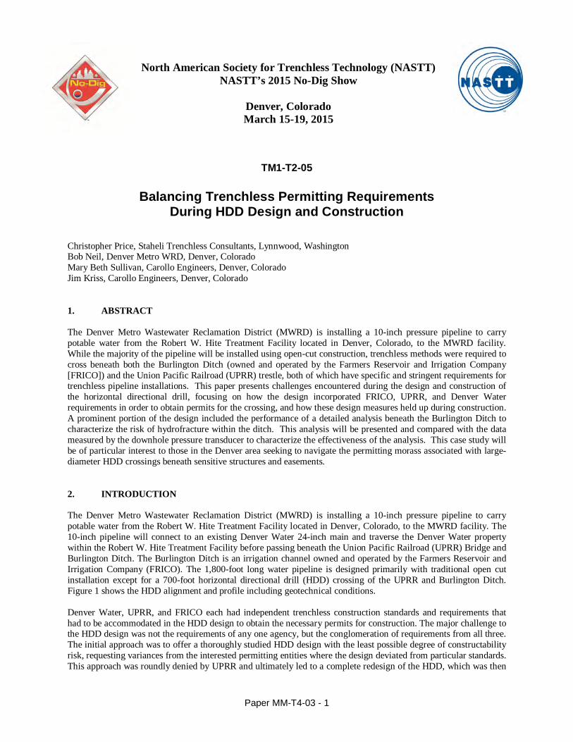
3. GEOTECHNICAL AND SITE CONDITIONS Soils along the HDD alignment generally consist of fill overlying alluvium, which in turn overlies sedimentary bedrock of the Denver Formation (Shannon and Wilson, 2013). The fill soils along the HDD alignment range from zero to eight feet below ground surface and consist of medium dense silty to sandy clay. The upper portion of the underlying alluvium generally consists of loose to medium dense, trace to silty or clayey, gravelly sand with scattered cobbles. These various soil types occur in layers ranging in thickness from about two to seven feet. The lower alluvium is more uniform at approximate elevation 5,108 feet (or approximately 25 feet below ground surface), consisting of medium dense to dense, slightly silty to silty, trace gravelly sand. Sedimentary bedrock of the Denver Formation was encountered approximately 40 feet below ground surface, or elevation 5,090 feet. The bedrock typically consists of very low strength, fresh to slightly weathered claystone, siltstone, and sandstone (Shannon & Wilson, 2013). Figure 1 illustrates the geotechnical conditions that were anticipated along the preliminary HDD alignment.
Figure 1. Geotechnical Profile along Preliminary HDD Alignment
FILL
(SP) ALLUVIUM
SPT (4-16)
DENVER FORMATION
(Claystone)
(SW-SM) ALLUVIUM
SPT (24-40)
Trestle Piers
BURLINGTON DITCH
HDD EXIT HDD ENTRY
RR Trestle
Paper MM-T4-03 - 3
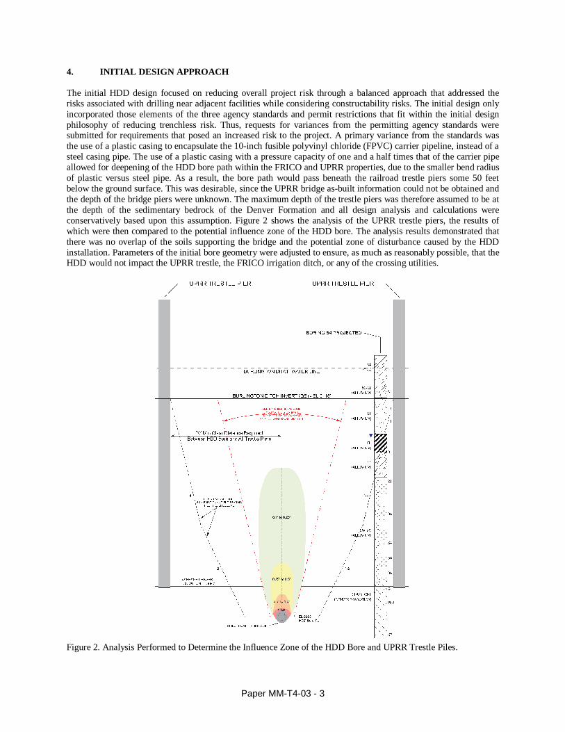
4. INITIAL DESIGN APPROACH The initial HDD design focused on reducing overall project risk through a balanced approach that addressed the risks associated with drilling near adjacent facilities while considering constructability risks. The initial design only incorporated those elements of the three agency standards and permit restrictions that fit within the initial design philosophy of reducing trenchless risk. Thus, requests for variances from the permitting agency standards were submitted for requirements that posed an increased risk to the project. A primary variance from the standards was the use of a plastic casing to encapsulate the 10-inch fusible polyvinyl chloride (FPVC) carrier pipeline, instead of a steel casing pipe. The use of a plastic casing with a pressure capacity of one and a half times that of the carrier pipe allowed for deepening of the HDD bore path within the FRICO and UPRR properties, due to the smaller bend radius of plastic versus steel pipe. As a result, the bore path would pass beneath the railroad trestle piers some 50 feet below the ground surface. This was desirable, since the UPRR bridge as-built information could not be obtained and the depth of the bridge piers were unknown. The maximum depth of the trestle piers was therefore assumed to be at the depth of the sedimentary bedrock of the Denver Formation and all design analysis and calculations were conservatively based upon this assumption. Figure 2 shows the analysis of the UPRR trestle piers, the results of which were then compared to the potential influence zone of the HDD bore. The analysis results demonstrated that there was no overlap of the soils supporting the bridge and the potential zone of disturbance caused by the HDD installation. Parameters of the initial bore geometry were adjusted to ensure, as much as reasonably possible, that the HDD would not impact the UPRR trestle, the FRICO irrigation ditch, or any of the crossing utilities.
Figure 2. Analysis Performed to Determine the Influence Zone of the HDD Bore and UPRR Trestle Piles.

Paper MM-T4-03 - 4
The anticipated geotechnical conditions were considered in the initial design of the HDD bore geometry. Given their density and fines content, the near-surface alluvial soils were considered relatively good for directional drilling; however, cobbles can pose borehole stability problems and steering issues. Improved drilling was expected with depth, within the deeper soils absent of scattered cobbles. The initial design accounted for this with a straight trajectory from the entry that would not require steering until the lower, more stable, uniform soils were encountered. A steep entry angle of 20 degrees was selected to reach the more competent alluvium quickly and gain depth while within the FRICO ROW. The bore was initially designed to be entirely within the more competent soils while within the FRICO ROW, and enter into the sedimentary bedrock of the Denver Formation while passing between the UPRR bridge piers (Figure 1). Thus the bore geometry was chosen to minimize the distance traversing soft or loose soils, maintain the bore in the ideal competent soils while in the FRICO ROW, and ensure the bore was fully within bedrock when passing between the UPRR bridge piers. The use of a plastic casing pipe allowed the flexibility necessary to adjust the borehole geometry parameters in response to the anticipated geotechnical conditions. A plastic carrier pipe does not require cathodic protection, increasing the effective life of the system. Cathodic protection can be provided for steel pipe or the wall thickness increased for the design life; however, it is expensive, and if there are deficiencies in the protection system, corrosion may still occur. In addition to the request to utilize plastic instead of steel casing, the initial design eliminated the use of casing spacers between the 10-inch carrier pipe and the 16-inch casing pipe. By doing so, the casing pipe and HDD borehole diameters could be reduced. Decreasing the borehole diameter lowered the potential for surface settlement near the entry and exit locations. Furthermore, the smaller diameter proportionally increased the separation distance of the bore path from the bottom of the FRICO irrigation ditch as well as the existing utilities to be crossed.
5. HDD REDESIGN FOR THE MOST ARDUOUS PERMIT REQUIREMENTS Despite the careful analysis and technical documentation presented to explain the reduced risks that could be realized by variances from permitting standards, the variance requests and permit application were denied. After the initial design and variance requests were rejected, a second design was pursued based on an entirely different philosophy. The redesign was a study in mitigating extremes and consisted of selecting the “worst case” parameter for each of the permit requirements. A table combining the permitting requirements of the three interested agencies was developed to track the selection of the various design parameters along with mitigation efforts added to offset resulting increases to project risk. Table 1 shows a condensed version of the spreadsheet that was used to select the dominant, i.e., most arduous, requirements and the proposed mitigation efforts. Approximately one-third of the requirements have been omitted from Table 1 for clarity in publication. It is clear when examining current standards developed for the various agencies that requirements have been developed as “catchall” standards that are improperly employed for all trenchless installations, which historically meant pipe jacking methods. The more dated requirements are not remotely applicable to HDD installations; for instance, the 2013 AREMA Manual for Railway Engineering requires that the “maximum borehole diameter will be no more than 2 inches larger than the outside diameter of the installed carrier or casing pipe.”(AREMA, 2013) This requirement is in direct contradiction to the HDD industry accepted practice of sizing the final borehole diameter to be either 12 inches larger or 1.5 times the outside diameter of the installed pipe, whichever is less. (Bennett, D., and Ariaratnam, S., 2008) Presumably the 2-inch maximum overcut requirement was originally developed for pipe jacking installation methods where it is applicable to prevent excessive systematic settlement within the ROW. Typically, HDD installations are much deeper than pipe jacking installations, thus negating the likelihood of potential surface settlement. It is the author’s opinion that in lieu of a 2-inch overcut restriction for HDD, the agency would be better served by eliminating the oversized steel casing and casing spacer requirements for HDD crossings which would actually reduce the final borehole diameter and dramatically decrease the magnitude of potential ground disturbance during construction and subsequent potential long term ground surface settlement. At over $20,000 per application, it is important that the HDD designer be able to understand and abide by the imposed permit requirements for HDD designed crossings. Currently, the myriad conflicting, often inapplicable, requirements make this a difficult proposition at best.

Paper MM-T4-03 - 5
Table 1. Comparison of Requirements Incorporated into the Final Design. The “Most Arduous” Requirements are Highlighted.
Ref AREMA Requirements Ref FRICO Requirements Ref Denver Water Requirements
(Material Spec - 34) Design Response:
5.3.2.a Pipelines must be encased in larger casing 5.3.1 steel casing full width of FRICO ditch 2 welded steel meeting AWWA C200 Design will comply accordingly.
5.3.2.c cross tracks at 90 degrees & no less than at
45 degrees
End points will control… will be
near perpendicular to RR.
5.3.2.f Pipeline must be able to be electronically
located. 5.3.4.2 marker posts required
locate wire will be pulled with
pipeline
5.3.3.a carrier pipe joints shall be leak proof or
welded 5.3.1 carrier pipe shall be restrained joints
fPVC will be butt fused for entire
length
5.3.3.c …PVC and PE pipe are approved carrier pipe
materials… 6
Carrier </=20-inches, Certa-Lok RJ or
fPVC pipe. fPVC carrier pipe will be used
5.3.3.c.5 MAOP = 100 psi. Plastic carrier pipe conform
to ANSI B31.3 5.3.3
pipe pressure rating 50% greater than
outside ROW. Pressure test is required.
Design requires a MOAP of ~200
psi.
5.3.4.a casing ID 4" > than carrier pipe joint OD 5.3.1 Min 3" clearance around carrier pipe 2 casing 10" larger than carrier DW for jacking. Will use 16" casing.
5.3.4.1 Steel casing SMYS of at least 35ksi 2 …minimum yield strength of 35,000 psi. Design will comply accordingly.
5.3.4.3 Casing pipe shall extend a min. 25 ft from
outside track when casing is below ground.
Design will require several
hundred feet of setback.
Table 1-5-
5
Min casing wall thickness (not coated or
catholically protected)
12.75" -- 0.188" / 14" -- 0.250" / 16" -- 0.281"
/ 18" -- 0.312"
5.3.1
Casing >12" but <24" diameter = 0.25"
wall steel pipe
Casing shall be suitably protected from
failure due to corrosion for a design life
of 50 years.
2
Designed to withstand applied loads.
External loading shall be AASHTO H20
HWY or RR loading plus jacking load, E-
80 RR loading. Min wall=0.375".
Design will use the most
conservative wall thickness
requirement of 0.375" to comply.
5.3.5 Casing installed to prevent the formation of a
waterway under the railway… 5.3.1
…casing shall be liquid tight & casing
sealed to the carrier pipe at each end. 5
EPDM or neoprene rubber end seals on
casing.
Design will use casing end seals
per Denver Metro requirements.
5.3.1 insulated casing spacers required. 4 Casing spacers required. Design will utilize slim casing
spacers
5.3.5.2.1 Casing pipe not less than 5.5 ft from base of
rail to top of casing. 5.3.4.1
top of the proposed pipe shall be not
less than 12 ft below the canal invert.
Hydrofracture design will control.
Min depth of 20 feet below ditch.
5.3.5.2.1 3 ft minimum cover at shallowest point 5.3.4.1 3 ft min cover within FRICO ROW Hydrofracture design will control.
Min depth of 12 ft within ROW.
5.6.2.1.b The location of the bore must not conflict
with any facilities within the RR ROW.
Cannot pothole utilities within
ROW until permits in construction.
5.6.2.1.c
Design track bores to be >150 ft from the
nearest bridge, culvert, road crossing, signal
structure, track switch, building or other
major structure.
Permit application and design will
conservatively treat going
between the bridge piers as if it
were a standard RR embankment.
5.6.2.1.d
Design bore pits to be a minimum of 30 ft
from centerline of track when measured at
right angles to the track.
5.3.4.2
Case bore operations under FRICO
canals shall be conducted outside the
FRICO ROW and the bore pits shall also
be located outside the FRICO ROW.
Design is extremely conservative in
this regard and will fully comply.
5.6.2.1.f Max borehole diameter no more than 2”
larger than the OD of the casing pipe.
Not possible with HDD
construction method Good
Practices.
5.6.2.1.k min depth of 5ft under natural ground, or
12ft under base of rail
Hydrofracture will control and
exceed the depth requirement
5.6.2.1.m
Constant slope for min of 30 ft from CL of
track, 2 ft beyond toe of slope and 3 ft
beyond ditch, whichever is greater.
Will provide a 60' tangent section
(0% slope) of the bore within the
UPRR ROW to meet this criteria.
The permitting standard that resulted in the greatest impact to the redesign was the requirement of steel as the casing material. Additionally, the requirement that casing spacers be used to place the carrier pipe within the steel casing with a minimum radial annulus of three inches severely limited adjustments to the bore geometry. The use of steel casing necessitated a bend radius of 1,600 feet which was over three times larger than the 500-foot bend radius used for the plastic casing pipe. This ultimately reduced the amount of separation below the FRICO ditch by eight feet as well as reducing the total depth of cover below grade by 18 feet where the bore passed between the UPRR bridge trestle piers. Thus, following the UPRR requirement led to a greatly reduced separation between the bore and critical trestle piers, increasing the risk of potential impacts to the piers during HDD construction. A balance was sought between an appropriate depth of cover below the critical crossing locations to prevent hydrofracture while allowing for entry and exit tangent sections that would reduce the potential risks of steering difficulties in the less competent near-surface soils with potential scattered cobbles. A much shallower exit angle was also incorporated in the redesign to reduce the difficulties of lofting the steel pipe during pullback. Calculations for the steel casing installation were performed based on the Hair approach (Hair, 1995). Pipe layout was also problematic when acquiring sufficient space to allow the contractor the ability to weld the entire length of the casing pipe above ground prior to pullback. There was limited available layout space in the Denver Water property that could be used by the contractor; however, development of arduous specification restrictions allowed the contractor to use a delineated portion of the property provided minimal disturbance occurred.

Paper MM-T4-03 - 6
6. HDD INFLUENCE ZONE AND BRIDGE PILE ANALYSIS
An analysis of the potential influence zone of the HDD installation was performed early in the design process and updated throughout as more information was obtained. This analysis incorporated a drilling fluid hydrofracture analysis as well as a potential settlement analysis to determine the maximum zone of influence that could be attributed to the HDD installation. The maximum zone of influence was then compared to the extent of the soil mass attributed to the support of the bridge trestle piles. Figure 3 shows one of the numerous iterations of the hydrofracture graph developed to analyze the amount of separation that would be necessary to prevent hydrofracture, or the release of inadvertent drilling fluid returns, to the FRICO ditch and the ground surface along the bore alignment.
Figure 3. HDD Hydrofracture Graph (Revised for Shallower Redesign of Bore Path) Figure 4 shows the settlement model used to calculate the potential soil disturbance caused by the HDD while passing beneath, or near, sensitive features. The settlement analysis is adapted from an idealized normal distribution curve originally proposed by Cording and Hansmire (1975) and modified by Bennett (1998). The author altered the modified model proposed by Bennett to calculate potential disturbance at discrete offset distances, both vertically and horizontally, from the HDD bore center. The resulting graph depicts bands of potential soil settlement radiating non-uniformly outward from the bore path. It should be noted that under a catastrophic settlement event caused by gross over-excavation, a localized vertical chimney effect can be conceptualized based on the vertical shaped bands of disturbance. Void propagation to the ground surface is typically seen in extreme conditions of gross over-excavation through operator error or poor execution during construction. The results presented in Figure 4 are colored based on magnitude, with values less than 0.1 inches assumed to be negligible and not shown for clarity. Actual ground disturbance observed in cases absent of gross over-excavation have proven to be smaller than values predicted by the normal distribution model, which is inherently limited by

Paper MM-T4-03 - 7
assuming uniform soil properties for the soil mass in question. Thus, engineering judgment based on experience is important to ensure conservative yet useful results are obtained from the analysis.
Figure 4. HDD Settlement Analysis Results Varied by Depth Adapted from Bennett, 1998.
7. CONSTRUCTION The redesigned bore path crosses numerous existing utilities, many of which could not be potholed until start of construction. (Figure 5) The 78-inch Platte River Interceptor pipeline is crossed in two locations, once at entry and again near the exit point. Other nearby utilities include a duct bank, large fiber optic cable, and two diesel fuel lines within the UPRR ROW. Key utility potholes, including the two diesel fuel lines and large fiber optic communication line, were only allowed to be potholed during construction after the contractor obtained the necessary permits. During design, the fuel lines were assumed to be located at an approximate depth of eight feet below grade based on available information from the utility owner; however, the lines were actually found to be located at an average depth of 23 feet below the ground surface. Locating the fiber optic line proved to be quite difficult and became extremely time consuming and costly. After several weeks of attempting to advance cased vacuum excavated potholes to depths sufficient to locate the fiber line, the decision was made to proceed with the HDD bore without actually locating the line. The decision to suspend the pothole operation was reached after advancing the pothole well below the elevation of the HDD bore on both sides of the bore centerline. The owner of the fiber line suggested that the line was ten or more feet below the termination depth of the exploratory potholes, although they did not

Paper MM-T4-03 - 8
actually confirm the depth of the line. After discussions with the contractor, it was decided that HDD would commence and that as long as the contractor did not deviate from the specified vertical tolerance of ±3 feet, that it would be unlikely to impact the un-located fiber optic line.
Figure 5. Final Bore Path with Obstacles Including Existing Utilities In an attempt to help the contractor expedite submittals it was agreed by the construction management team to allow piecemeal or partial submittals in whatever order or level of completion the contractor deemed appropriate. This submittal process proved to be less than ideal, and in response, an extensive submittal tracking spreadsheet was developed to track submittals by level of completion along with detailed comments for incomplete or conflicting submittals. The degree of difficulty for submittal preparation was certainly impacted by the morass of requirements included in the HDD specification necessary to ensure compliance with the three permitting agency standards and guidelines. Ultimately a series of conference calls including regular distribution of the submittal tracking spreadsheet to the contractor proved successful to increase the efficiency of the submittal process. The construction management team facilitated regular discussions between the trenchless subconsultant and the trenchless subcontractor during the submittal review that not only expedited the process, but also developed a line of communication that proved invaluable when issues occurred during construction. One of the primary issues that presented itself early on in the project was the area available for setup of the drill rig at the proposed entry point. The contractor decided to mobilize a larger drill rig which would allow forward reaming with a single upsize to the final 24-inch bore diameter. However, the use of a larger rig than that anticipated during design necessitated a change in the entry location and partial removal of an existing high security fence. The design team quickly incorporated the new entry point, bore path changes, and pothole utility information into a revised HDD bore path that allowed the contractor space for equipment while complying with the various permit restrictions. During this phase of the project, the contractor also proposed employing a 4-inch drilling fluid return line with a mud pit pump setup at the exit pit which was fused together beneath the railroad trestle and over the Burlington Ditch back to the entry pit. The mud return line was proposed to reduce the number of vacuum truck trips required to transport drilling fluid from the exit to the entry site for recycling.
EXISTING UTILITIES
Fiber Optic Line (Max Depth Potholed)
Diesel Fuel Lines
UPRR Bridge Trestle Piers
HDD ENTRY HDD EXIT

Paper MM-T4-03 - 9
A two degree bent sub and a jetting assembly were used to drill the 8-inch diameter pilot bore. (Figure 6. Left) Ultimately, the pilot bore was completed in three days, including delays due to inadvertent drilling fluid returns to the ground surface after drilling approximately 400 feet, or two-thirds of the bore. Drilling fluid was seen escaping to the ground surface at the location of the fiber optic line pothole which had been backfilled with grout. (Figure 6. Right) Because of surface access restraints, the vacuum excavations performed to pothole the fiber optic line were unable to be offset by any appreciable distance from the HDD bore path centerline. The downhole annular pressure was monitored while drilling and no increased fluid pressure was observed prior to the inadvertent drilling fluid returns reaching the ground surface. The only indication of hydrofracture was a decrease in fluid returns to the entry mud pit. The drilling fluid was immediately contained and removed with a vacuum truck. Pilot bore drilling resumed with the escaping drilling fluid removed using the vacuum truck. A crew member remained stationed at the location of the inadvertent drilling fluid returns for the duration of the HDD in order to monitor and collect drilling fluid migrating to the ground surface.
Figure 6. Pilot Jetting Assembly with Mill Tooth Bit (Left) / Inadvertent Drilling Fluid at Pothole Location (Right) A single 24-inch diameter forward reaming pass (Figure 7. Left), pushed from the drill rig entry side, was performed using a fluted reamer that proved very successful in the alluvium soils. Forward reaming was completed in six days without major incident. Severe cold weather interrupted the drilling operation with a decision to postpone reaming for two days when temperatures were well below freezing. Drill pipe tail string was utilized at all times throughout the forward reaming operation, with an excavator used to provide tension on the drill string at the exit site. Drilling fluid continued to flow from the ground surface at the intermediate inadvertent drilling fluid return pit but was successfully contained and hauled to the mud recycling plant with a vacuum truck.
Figure 7. 24-inch Fluted Reamer (Left) / 10-inch Fusible PVC with Casing Spacers Pushed into the 16-inch Steel
Casing Installed via HDD (Right)

Paper MM-T4-03 - 10
The contractor elected to deviate from the initial plan to pull the entire steel casing with FPVC carrier pipe string in one continuous pullback operation. The contractor was allowed to pull the steel casing in two segments with an intermediate weld performed during pullback that took just under three hours with the total pullback performed in six hours including the intermediate weld. After completion of the 16-inch steel casing pullback, the 10-inch FPVC carrier pipe was then pushed into the steel casing with casing spacers used to guide the PVC pipe into place. (Figure 7. Right) 8. CONCLUSIONS
Although the HDD installation was successful, the permit restrictions proved onerous during design and construction. The use of plastic casings should be considered by permitting agencies in order to provide more flexibility to the HDD designer which could reduce project risk and risks to the facility owners. The advancements in plastic pipes are ongoing and in certain pressure ranges, plastic casings could provide the facility owner with assurance that if in operation the carrier pipe were breached, that a plastic casing would effectively contain the fluid and prevent damage to the crossing facility. This is certainly the case for the majority of water and wastewater crossings. The same considerations should be made for eliminating the use of casing spacers for HDD crossings that utilize plastic carrier and casing pipes. The use of casing spacers should not be a mandatory requirement for these crossings, but only employed at the pipe system designer’s discretion. Eliminating the requirement of using casing spacers would reduce the overall casing diameter, and in turn reduce the required HDD borehole final ream diameter. Reducing the HDD bore diameter decreases overall cost, magnitude of potential ground disturbance, and generally reduces the overall HDD risk profile. This particular project was successful primarily because of the level of concern and conservatism brought to bear by the design team. In spite of the permitting requirements, the design team consistently favored reduction of construction risk and decreased impacts to interested facility owners over project cost concerns. It should be noted that as a direct result of the analysis and engineering effort expended during the permitting process, FRICO has reevaluated and subsequently updated its HDD permit restrictions and trenchless installation standards to comport with current advances in trenchless construction. Permitting agencies should be aware that enforcing stringent individual permit requirements at every turn does not inherently result in a low risk or conservative HDD design. As this project demonstrates, quite the opposite can be true when combining many seemingly conservative restrictions that culminate in increased risk. Hopefully this project may serve as an example of why a one-size-fits-all approach to HDD permitting should not continue to be the standard of practice for interested agencies.
9. REFERENCES AREMA (2013) – American Railway Engineering and Maintenance-of-Way Association, Part 5 Pipelines, Subpart 5.6 Specification for Horizontal Directional Drilling (HDD) Construction on Railroad Right-of Way. Bennett, D. (1998) – Jacking Loads and Ground Deformations Associated with Microtunneling, Doctoral Thesis. University of Illinois, September. Bennett, D., and Ariaratnam, S. (2008) – Horizontal Directional Drilling Good Practices Guidelines, North American Society for Trenchless Technology (NASTT), Third Edition, USA Cording, E.J., and Hansmire, W.H. (1975) – “Displacements Around Soft Ground Tunnels,” Proceedings, 5th Pan American Congress on Soil Mechanics and Foundation Engineering, Buenos Aires, Argentina. Hair, J.D. (1995) – Pipeline Research Committee International of the American Gas Association “Installation of Pipelines by Horizontal Directional Drilling, An Engineering Design Guide, Contract No. PR-227-9424, April 22. Staheli, K., Price, C., and L. Wetter (2010) – Effectiveness of Hydrofracture Prediction for HDD Design, North American Society for Trenchless Technology (NASTT), No Dig Show May 2 - 7, Chicago, Illinois. Shannon and Wilson, Inc. (2013) – Geotechnical Report Metro Wastewater Reclamation District PAR 1085, Potable Water Supply Pipeline Project, January 14.