ballast and lighting control fagerhult 2006 - evu mwg april 07 swe... · luxmate instabus. lighting...
TRANSCRIPT

Ballast and Lighting Control
FAGERHULT 2006

DEVELOPMENT

1940Automobile
Telephone
Ballast
1950
Telephone
Automobile
Ballast

1960
Telephone
Automobile
Ballast

1970
Telephone
Automobile
Ballast

1980
Telephone
Automobile
Ballast
1984Tidig variant av hf-don med magnetiska filter

1990
Telephone
Ballast
Automobile
En enhet enklare koppling, lägre energiförlust.

2000
Telephone
Automobile
Ballast
…1…2…3…4…5
Låg profil, multifunktion, olika belastningar, processor kontroll och DALI
…6

Ett gammalt hf-don väger 3,5 gånger fler än nya

Dimmable light sourses

Incandescent lamps and halogen,
tungsten
Dimming range 0-100%
Dimming extends lamp life (5% of dimming doubles the
life time.)
Dimming = energy saving
Any kind of dimming technology works
Big loads can get a humming noise from the filament

38mm Fluorescent tube
Dimming range 20-100% depending on tube (standard or
rapid start)
Used in old applications. Dimmer with thyristor dimmer
and pre-heat transformer or old electronic gear.
The inductive load stops the dimmer from being fully
used.
Flickering light with pre-heat transformer
Dimmer must be made for inductive loads

26mm Fluorescent tube
Dimming range 1-100%
Dimming with 1-10V, DSI or DALI.
Early dimming technology was made with
electronic pre-heat units and conventional ballasts.
This was not a HF-dimming. It easily caused
flickering light.

Compact tubesOnly compact tubes with 4 pins are dimmable.
Dimming range 5-100%.
Needs electronic ballast for dimming

Small compact tubes
Incandescent replacement
Small energy saving flourecent lamps has electronic gear
built in. The electronics main focus is to maintain a stabile
and flicker free output. This is a contradiction to dimming.
Do not dim. The capacitive load can break the dimmer.

T5 Fluorescent tube
Dimming range 1-100%
Works only with electronic ballast .
Also as circular tube
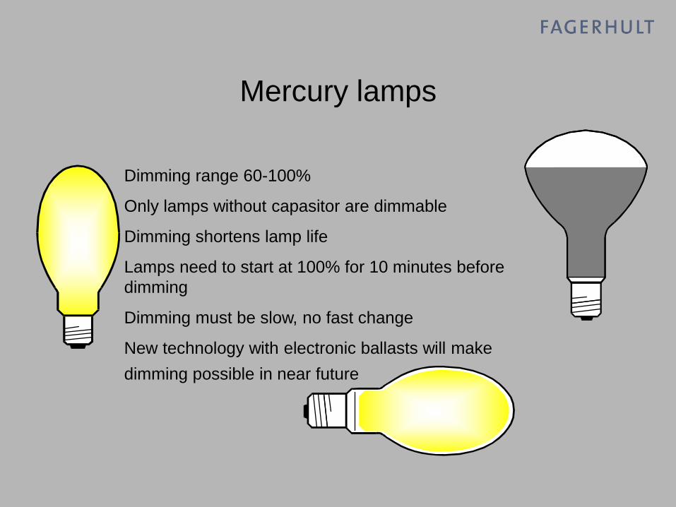
Mercury lamps
Dimming range 60-100%
Only lamps without capasitor are dimmable
Dimming shortens lamp life
Lamps need to start at 100% for 10 minutes before
dimming
Dimming must be slow, no fast change
New technology with electronic ballasts will make
dimming possible in near future

High pressure sodium
Dimming range 50-100%, lower for short periods
Only lamps without capasitor are dimmable
Dimming shortens lamp life
Lamps need to start at 100% for 10 minutes before
dimming
Dimming must be slow, no fast change

Metal Halide
Dimming range 50-100%,
Dimming affects light colour
Flickers easily during dimming
Only lamps without capasitor are dimmable
Dimming shortens lamp life
Lamps need to start at 100% for 10 minutes before
dimming
Dimming must be slow, no fast change

Low pressure sodium
No
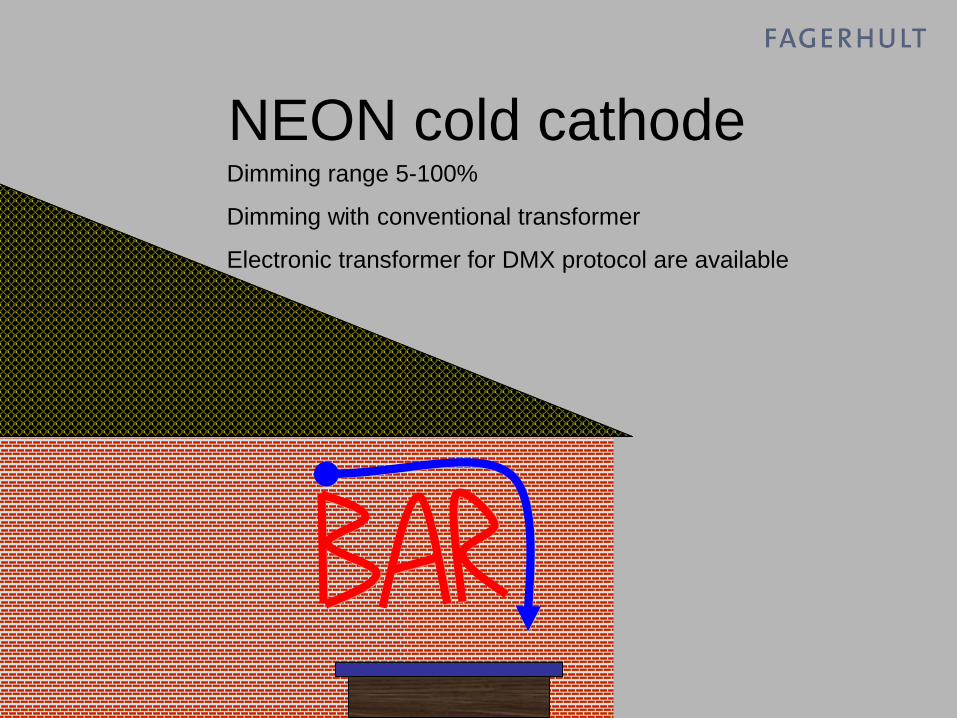
NEON cold cathodeDimming range 5-100%
Dimming with conventional transformer
Electronic transformer for DMX protocol are available

LED
Dimming range 0-100% (voltage control)
Dimming with special electronic transformers or converters
Dimming with pulse or voltage control
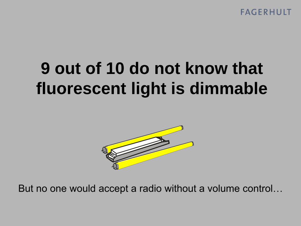
9 out of 10 do not know that
fluorescent light is dimmable
But no one would accept a radio without a volume control…

Different ways of dimming

230V
Dimmable hf-ballasts
230V 12V
Thyristor dimming
Thyristor dimming is the most common way of controlling
a resitive or inductive load. Also know as leading edge
dimming.
Noise reduction is needed.
Creates massive harmonics on mains.
A coil is used to reduce voltage spikes.
Dimmer size from 300VA -5500VA.

230V
Leading edge
dimming
Dimming circuit Filter choke
Thyristor dimming

Dimmer for
control with
external switch
250VA
Dimmer for
domestic use
Wallbox mounted
300-1000VA
Universaldimmer
DIN-rail mounting
500-2000VA Dimmer for large
loads
2200-5500VA

230V
Transistor dimming
Transistordimming also known as trailing edge dimming. A
more complicated way of dimming, but with good result.
Dimms without any noise and are useful in sensitive
installations.
Dimms resitive and capasitive loads.
Creates harmonic distubance om mains.
Transistor dimmers are often used for dimming electronic
transformers.
Shall not be used for dimming conventional transformers!
Dimmers from 300VA -2200VA.
230V 12V
Electronic transformer

230V
Trailing edge
dimming
Dimming circuit
Transistor dimming

230V
SINEWAVE DIMMING
Sinewave dimming is the latest invention in dimming
technology. The energy input is sampled at a high
frequency and controlled out with a lower volt/current;
very much like amplitude control from a Variac
transformer!
The first electronic dimmer that do not creats harmonics!
Phase Input Phase Out
DIMMS EVERYTHING!

The output current waveform is smoothed using a
passive network to produce an output waveform
that accurately represents the waveform profile of
the incoming supply. The PWM process adds less
than 1% distortion to the mains supply, resulting in
a completely silent dimmer with a remarkable
facility for dimming almost any load.
Overall benefits of Sine Wave dimming:
Lamp filament noise eliminated
Extended lamp life due to elimination of load switching and
reduced peak voltage
Less than 1% harmonic distortion reduces power costs
Unity Power Factor
Minimum 96.5% efficiency to a maximum of 99%
"Any load" operation (dims the widest variety of loads of any
dimmer)
Total short-circuit and overload protection without breaker tripping
230V
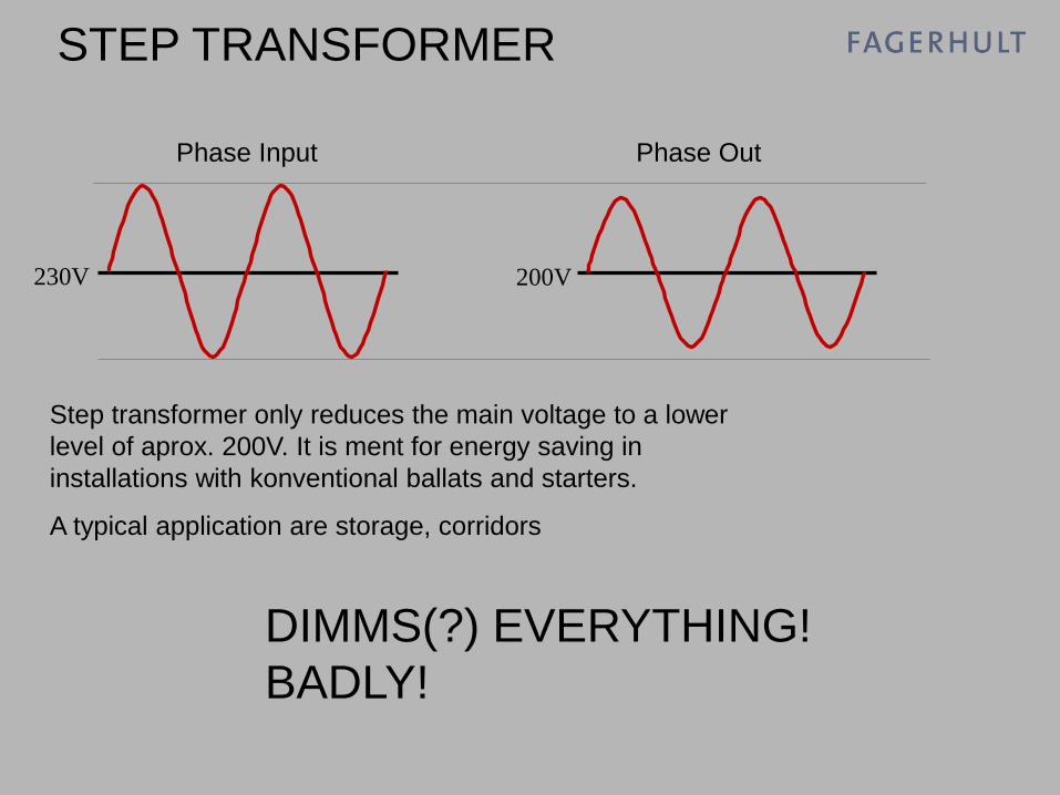
STEP TRANSFORMER
Step transformer only reduces the main voltage to a lower
level of aprox. 200V. It is ment for energy saving in
installations with konventional ballats and starters.
A typical application are storage, corridors
Phase Input Phase Out
DIMMS(?) EVERYTHING!
BADLY!
200V

Lighting control; how?
EIBECHLON
DMX
DSI
DALI
1-10V
0-10VPWM
20V current control
BATIBUS
RS232
RS485
IHC X10IR command
C-busTransistor dimming
Tyristor dimming
Sinewave dimming
RF control
And about 20 more…
Switch Control
Step transformer
Luxmate
Instabus

Lighting control; divided how?
EIB ECHLON
DMX
DSI DALI1-10V
0-10V PWM
20V current controlBATIBUS
RS232 RS485
IHC
X10
IR command
C-bus
Transistor dimming
Tyristor dimming Sinewave dimming
RF control
BMS
Theatre
HF-Ballast
Domestic
Industrial C-bus
IHC RF controlEIB
Audo Visual
Tyristor dimming
Transistor dimming
Tyristor dimming
Pulse switch Control
Luxmate Instabus

Lighting control; ballast?
DSI DALI1-10V
HF-Ballast
PULSE CONTROL
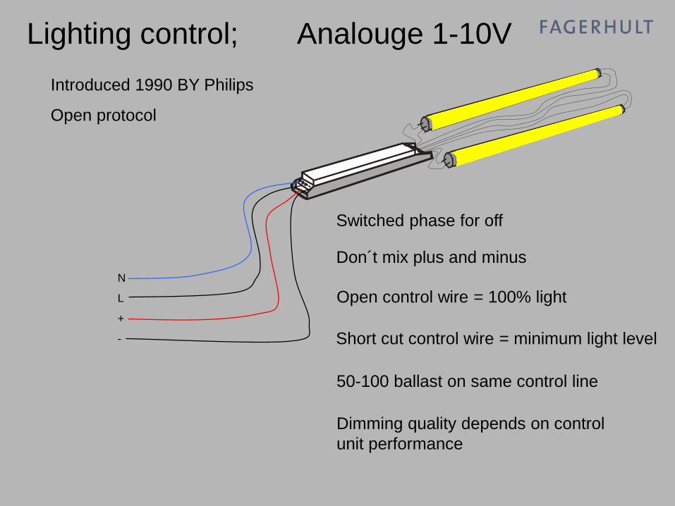
Lighting control; Analouge 1-10V
N
L
+
-
Switched phase for off
Don´t mix plus and minus
Open control wire = 100% light
Short cut control wire = minimum light level
50-100 ballast on same control line
Dimming quality depends on control
unit performance
Introduced 1990 BY Philips
Open protocol

Lighting control; Analouge 1-10V
N
L
+
-
CONTROL WIRES ARE ONLY
SINGLE ISOLATED FROM MAINS!
Distance between mains and control
wires are less then 8mm and under
4kV.
Control wires must be treated as live!
The same for DSI and DALI

Lighting control; Analogue 1-10V
L N
Sw
itc
he
d p
has
e
PL
US
MIN
US
CONTROL UNIT
•10VDC = max output 100%
•1VDC (or less) = min. output
(depending on the ballast dimming
quality)
10V1V0V
100%
0%
Min.
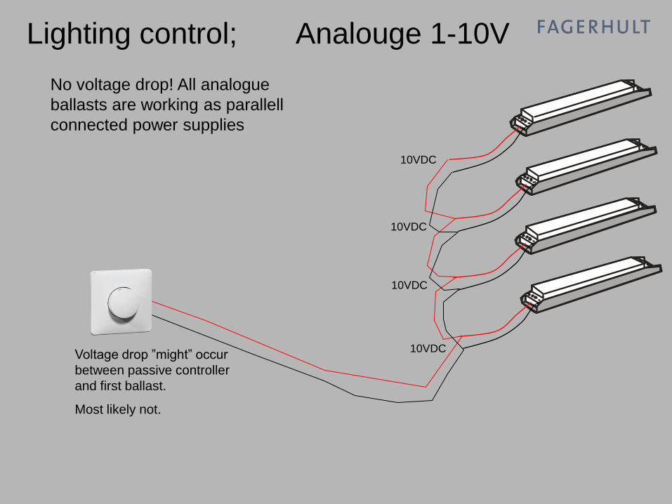
Lighting control; Analouge 1-10V
10VDC
No voltage drop! All analogue
ballasts are working as parallell
connected power supplies
Voltage drop ”might” occur
between passive controller
and first ballast.
Most likely not.
10VDC
10VDC
10VDC

Lighting control; Analouge 1-10V
10VDC
Ballast with plus and minus shifted
will stay at minimum light level
10VDC
10VDC
10VDC

Lighting control; Analouge 1-10V
2mA
Maximum current per ballast is 2mA.
Today is 0,5mA more common.
2mA
2mA
2mA8mA
All control units made for ballast control can
operate 100mA (equal to 50 ballasts)
Audio Vision systems needs a amplifier to
interface the high current.
AV output works normally with only 5-10mA

Lighting control; Analogue 1-10V
•Open control wire will give 100% light
output.
•Short circuit of the control wire will set
light level to minimum.
•Minimum level is a function internally of
the ballast and will differ between
manyfacturer and lamp type.
Open control line and short circuit

Lighting control; Analogue 1-10V
•A resistor can be used to set a low fixed
output level. A 50k potentiometer can be
used for a simple adjustable setting.
•The value of the resistor will change with
the amount of ballasts.
•All control units made for ballast dimming
are voltage controller, not resistor based.
50kohm
Resistor control

Lighting control; Analogue 1-10V
•Open control wire will give 100% light
output.
•Short circuit of the control wire will set
light level to minimum.
•This can be a useful function in a corridor
if a movement detector controls the
function.
PIR control of two light output levels
50kohm
Like a special Discovery Space e-Sense?

Lighting control; Analogue 1-10V
L N
Sw
itc
he
d p
has
e
PL
US
MIN
US
Relay function, mains controlled
•Electronic control units normally has an
intelligent way of opening the relay after
light level has been dimmed down to
minimum.
•Manually controlled potentiometer can
turn off the light at any point. A kind of
”memory” level.
NOTE!
Allways check the relay/switch quality!
Specification should define how many ballasts can be
connected to the relay/switch.

L
N
PE
+
-
PE
N
L1
L2
L3
L
N
PE
+
-
2
3
4
6
7
-
+
Plint
2
3
4
6
7
-
+
Plint
Electronic ballast
Helvar
Philips
Osram
Electronic ballast
Helvar
Philips
Osram
Contactor
L
N
PE
+
-
2
3
4
6
7
-
+
Plint
Electronic ballast
Helvar
Philips
Osram
Fitting
Fitting
Fitting
Lighting control; Analogue 1-10V
Relay function, mains controlled
multiple phases
Control signal is
”floating” and is
not sensitive of
phase quality.
A phase can be
turned off and the
change will not
affect the light
level of the
remaining
ballasts.

Lighting control; Analogue 1-10V
L N
Sw
itc
he
d p
has
e
PL
US
MIN
US
CONTROL UNIT
•Simple manual control from one point
•10VDC is supplied by the ballast
•Switch must be made to manouver ballast
inrush current, or an external relay can be
used
•More than 50 ballasts can be controlled
via 1-10V line
•Multiple control always needs a central
unit.
•Input to control unit can be one of many
different protocols.
•Many different ways to manouver;
pushbutton, sliders, IR, etc.
EIB, LON, Luxmate, DALI, RS485,
RS232, etc.

Lighting control; PULSE CONTROL
N
L
Off with Switch command
Phase puls control
15(?) ballast on same circuit
DIGITAL?
Different features from suppliers
Different connections from suppliers!!
Introduced 1995
Open protocol?
Aka
Switch Control
SwitchDim
Touch & Dim
TouchDim
Check it out your self!!!!!
Phase over switch
Short pulse for ON/OFF
Long pulse for dimming
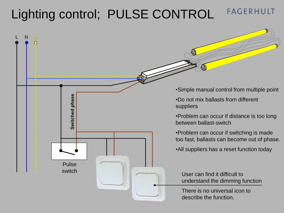
L N
Sw
itc
he
d p
has
e
•Simple manual control from multiple point
•Do not mix ballasts from different
suppliers
•Problem can occur if distance is too long
between ballast-switch
•Problem can occur if switching is made
too fast, ballasts can become out of phase.
•All suppliers has a reset function today
Lighting control; PULSE CONTROL
User can find it difficult to
understand the dimming function
There is no universal icon to
describe the function.
Pulse
switch

Lighting control; PULSE CONTROL
…and out of phase
If the switch is manouvered too fast,
the light sources can be controlled to
different levels.
E
N
L

Lighting control; PULSE CONTROL
E
N
L
Resetting after out of phase
Press and hold the switch for
10 seconds.
Light sources will dim to a
preset level, and the system
is ready to use again.
This can work in different ways depending on the manufacturer!

PE
N
L1
L2
L3
L
N
PE
DA
DA
2
3
4
6
7
DA
DA
Plint
L
N
PE
DA
DA
2
3
4
6
7
DA
DA
Plint
TRIDONIC ECO and One4all
Electronic ballast
Tridonic
Electronic ballast
Tridonic
Fitting
Fitting
CONNECTIONS

PE
N
L1
L2
L3
L
N
PE
DA
DA
2
3
4
6
7
DA
DA
Plint
L
N
PE
DA
DA
2
3
4
6
7
DA
DA
Plint
OSRAM & Philips
Electronic ballast
Electronic ballast
Fitting
Fitting
CONNECTIONS

L
N
PE
+
-
PE
N
L1
L2
L3
L
N
PE
Plint
Plint
L
N
PE
+
-
Plint
Fitting
Fitting
Fitting
HELVAR EL-sc connection
Electronic ballast
Helvar
EL-sc
In this example is
one swtich wired
to Helvar EL-sc
ballasts. Note
that neutral is
used for the pulse
control.
Phase OR neutral
can be used
Electronic ballast
Helvar
EL-sc
Electronic ballast
Helvar
EL-sc
1
2
3
4
5
6
7
8
1
2
3
4
5
6
7
8
1
2
3
4
5
6
7
8
CONNECTIONS

L
N
PE
+
-
PE
N
L1
L2
L3
L
N
PE
Plint
Plint
L
N
PE
+
-
Plint
Fitting
Fitting
Fitting
HELVAR EL-si connection
Electronic ballast
Helvar
EL-si
Helvar EL-si
ballasts are using
the ”DIGIDIM”
connectors for
pulse control.
This means that a
fitting needs 5
wire connection.
The voltage over
the switch is only
16VDC, but
single isolated Electronic ballast
Helvar
EL-si
Electronic ballast
Helvar
EL-si
1
2
3
4
5
6
7
8
1
2
3
4
5
6
7
8
1
2
3
4
5
6
7
8
CONNECTIONS

Lighting control; DSI (digital serial interface)
N
L
DSI
DSI
Off with DSI command
No plus and minus
Open control wire = stop
Short cut control wire = stop
30 ballast on same control line
Dimming quality is digital - logarithmic
Introduced 1995
Only used by Tridonic

Lighting control; DSI (digital serial interface)
N
L
DSI
DSI
•Standard Manchester code
•8-bit commands
time
+5V
-5V
0V
The digital tranmission is quite slow,
but fast enough to control light.

Example of connection diagram DSI

L N
CONTROL UNIT
•A central unit is always needed.
•Input to control unit can be one of many
different protocols.
•Many different ways to control;
pushbutton, sliders, IR, etc.
Analogue 1-10V, EIB, LON, DALI,
RS485, RS232, etc.
DS
I
Tra
nsm
itte
r
Lighting control; DSI (digital serial interface)
A control unit is
even needed for
two button ”blinds”
control

DALI
09.00 Morgen kaffe
Teori omkring DALI.
10.30 Kaffe
Gennemgang af software digidim
“11.30 Frokost
Hands-on” Praktisk orienteret
undervisning i DALI.
14.30 Kaffe
Lidt omkring e-sense.
16.00 Afslutning
Kurset bliver meget teknisk orienteret!

Allt om DALI
FAGERHULT 2007
Mats Wernberg
Product Manager
Lighting Control


Definition
DALI

DALI Stöds av tillverkare
HF don
Philips
Osram
Helvar
Tridonic
VS
Hüco
Magnatec
Styrsystem
Philips
Osram
Helvar
Tridonic
INSTA
ECS
Eckerle
Hadler
m.fl.

Vad är DALI?
Ett tillägg till existerande norm EN60929 annex E
(HF-don prestanda).
Ett standardprotokoll för reaktorer med senaste
teknologi
En standardmetod för styrning av elektroniska
reaktorer via en digital kontrollsignal

Varför digitalt?
Digitala signaler är inte störkänsliga och stör inte
själva
Digitala signaler kan ge större mängder information
och tvåvägskommunikation
Digitala komponenter blir allt mindre fler
funktioner till mindre utrymme och kostnad

DALI liknar DSI…
N
L
DSI
DSI
•Standard Manchester code
•8-bit commands
time
+5V
-5V
0V
DALI är uppbyggt på två följande
8-bitars kommandon.
Med 1 start och 2 stoppbitar
DSI ”hör” DALI kommandon…

Styrsystem
Utvecklingspotential med DALI
Funktionerna för
användaren förändras
marginellt
StyrenhetDALI
HF don
Det blir enklare att
projektera, installera, och
ändra i en anläggning

Hur man vill kontrollera DALI är fritt!
Olika sätt att kontrollera DALI
Centraliserad styrning:
En centralenhet komunicerar mellan styrfunktioner och
DALI belastningar
Exempelvis Osram, Altenburger, Insta, Nortronic och
Philips
StyrenhetDALI
HF donkontrollenhet

Hur man vill kontrollera DALI är fritt!
Olika sätt att kontrollera DALI
Decentraliserad styrning:
Komunikation sker mellan styrfunktioner och DALI-
belastningar endast på DALI
Exempelvis Helvar, Tridonic och Philips
DALIHF don
kontrollenhet

DALI standarden föreskriver ljusnivåer så att de överensstämmer
med den logaritmiska reglerkurva som det mänskliga ögat ser som
en linjär ljusförändring.
Alla DALI reaktorer använder samma logaritmiska kurva oavsett
deras absoluta mininivå.
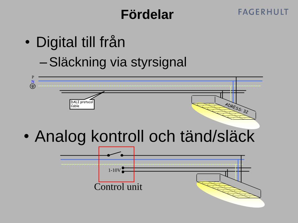
Fördelar
100%
0%
1%
NP
DALI protocolCable
• Analog kontroll och tänd/släck
Control unit
1-10V
• Digital till från
– Släckning via styrsignal
Fördelar

100101001110 100101001110
• Backchannelling (tvåvägskommunikation)
– Reaktorstatus (on/off)
– Lampeffekt (%)
– Reaktor status (fel/ standby)
Fördelar

• Polaritetsfri kontrollsignal
– Minskar möjlighet till installationsfel
Fördelar
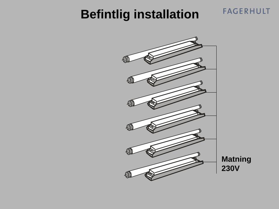
Matning
230V
Befintlig installation

Matning
230V
1-10V
StyrenhetInput
1-10V
StyrenhetInput
Matning
230V
Lösning med traditionell teknik

Matning
230VDALI
StyrenhetInput
Matning
230V
Lösning med DALI

Matning
230VDALI
StyrenhetInput
Lösning med DALI
Nyinstallation

1...10V DALI
Potentialfri styrning (3-fas
installation)
Potentialfri styrning (3-fas
installation)
Reglerområde 1...100% Reglerområde 1...100%,
logaritmisk kurva
Ingen
tvåvägskommunikation
Individuell status rapportering
Ej adresserbar Adresserbart individuellt, i
grupp, och alla (broadcast)
Minne för ljusscener
Programerbar reglertid
Kontrollkabel 2 ledare,
polatitetsbestämd
Kontrollkabel 2 ledare,
polaritetsfri
1-10V jämfört med DALI
• Integrerad till/frånTänd/släck med strömbrytare
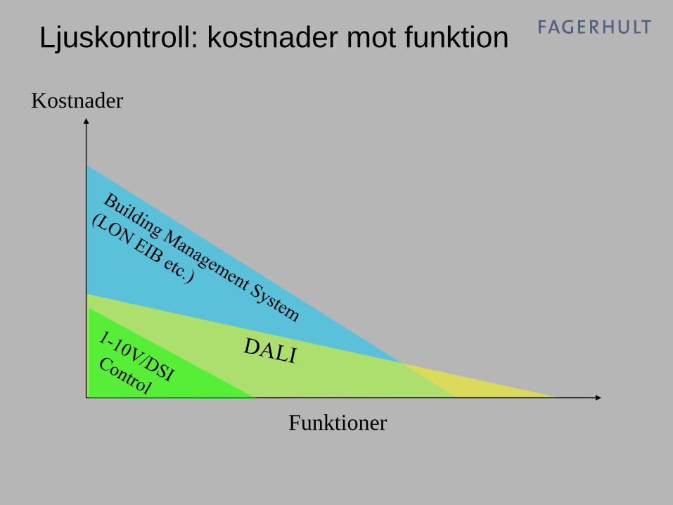
Kostnader
Funktioner
Ljuskontroll: kostnader mot funktion

Jämförelse mellan olika system
1..
.10
V
oc
h D
SI
Styrsystem
för hela
fastigheten
Våningsplan
eller delar
av hus
Enskillda rum
Fastighetsstyrning t.ex. EIB eller LON med
kontroll av värme & ventilation, jalusier och
markiser samt övervakningssystem och
belysning
Mindre system som agerar liknande ett
buss-system, men utan alla
samverkande funktioner
Digital eller 1-10 V kontroll
enheter
Pris &
kom
ple
xitet
DA
LI
EIB
ell
er
LO
N

DALI och styrsystemet
1. DALI-protokollet definierar HF-donets gränssnitt
1. Ingen gemensam standard för
styrkomponenter !
1. HF-don av olika fabrikat kan användas, men
styrkomponenter av olika fabrikat BÖR inte blandas

Kontrollfunktioner i DALI

Address 1
1 2 3 ...
... ... 63 64
1 2 3 ...
... ... 15 16
1 2 3 ...
... ... 15 16
1
Group 1
Address 2 Group 2
Address ... Group ...
Address 63 Group 2
Address 64 Group 16
64 individuella
adresser (HF-
don)
Individuella adresser

Address 1
1 2 3 ...
... ... 63 64
1 2 3 ...
... ... 15 16
1 2 3 ...
... ... 15 16
1
Group 1
Address 2 Group 2
Address ... Group ...
Address 63 Group 2
Address 64 Group 16
64 individuella
adresser (HF-
don)
Individuella adresser

Address 1
1 2 3 ...
... ... 63 64
1 2 3 ...
... ... 15 16
1 2 3 ...
... ... 15 16
2
Group 1
Address 2 Group 2
Address ... Group ...
Address 63 Group 2
Address 64 Group 16
16 grupp-
adresser
Gruppering

Address 1
1 2 3 ...
... ... 63 64
1 2 3 ...
... ... 15 16
1 2 3 ...
... ... 15 16
2
Group 1
Address 2 Group 2
Address ... Group ...
Address 63 Group 2
Address 64 Group 16
16 grupp-
adresser
Gruppering

Address 1
1 2 3 ...
... ... 63 64
1 2 3 ...
... ... 15 16
1 2 3 ...
... ... 15 1615
Group 1
Address 2 Group 2
Address ... Group ...
Address 63 Group 2
Address 64 Group 16
15
15
15
15
15
16 ljusscener
(lagras i HF-donen)
Individuellt lagrade ljusscener
INSTALLATIONSEXEMPEL

Gruppering i kontorsplan

Praktiska hållpunkter för
installationer

Praktiska hållpunkter för
installationer
Maximal längd installationskabel:
300m eller ett maximalt spänningsfall på 2V
Enligt AG DALI har praktiska fall visat på följande:
Längd Kabeldiameter
Upp till 100m 0.5 mm2
100-150m 0.75mm2
150-300m 1.5mm2

DALI Basics
Praktiska hållpunkter för installationer
Inget krav på installations ordning
DALI kan installaleras i seriell slinga, stjärnnät eller i
kombinationer därav

DALI Basics
Praktiska hållpunkter för installationer
DALI är galvaniskt skilt från ansluten fas -olika faser kan anslutas till olika belastningar
Ingen slutterminering med motstånd-Jmf med bussystem, där ett eller flera motstånd skall
anslutas för balansering av systemet.

DALI Basics
Praktiska hållpunkter för installationer
DALI och 230V i samma kabel -Den långsamma överföringshastigheten och
enkelisoleringen gör att DALI med fördel kan förläggas i
samma kabel som nätspänning t.ex. till en armatur.

DALI Basics
Praktiska hållpunkter för installationer
DALI Strömförsörjning Max 250mA kan försörja ett DALI system
Det kan användas till 2mA/belastning eller i större mängd till
olika kontrollkomponenter; paneler, sensorer m.m
2mA 250mA
10mA
• Exakta kommandon – även på långa avstånd
• Tändning, släckning och ljusreglering över DALI-bussen
• Ej polariserad buss - mindre risk för felkoppling
• Bussen kan förläggas i samma rör eller kabel som nätspänningen
• Felmeddelande kan erhållas från de digitala DALI-donen
• HF-don för DALI kan adresseras och kontrolleras individuellt
• HF-don för DALI kan tillhöra max 16 grupper och lagra max 16
ljusscener
DALI - egenskaper i korthet

• Scen- och gruppinformation lagras i HF-donet
• Felmeddelande, status ( on/off, aktuell ljusnivå, defekt ljuskälla...)
• Programmerbara parametrar i HF-donet, som tex ljusregleringshastighet,
och HF-donets reaktion vid brott på DALI-bussen mm
• Ljusregleringsområde beror på det aktuella HF-donet. DALI-protokollet
specificerar ljusregleringsområdet från 0,1 till 100 %
DALI - egenskaper i korthet

PRODUKTER

Närmast ljuskällan,
belastning:HF-don för alla typer av lysrör

Närmast ljuskällan,
belastning:Dimmrar
Universaldimmer
1000VA
Tyristordimmer
16A
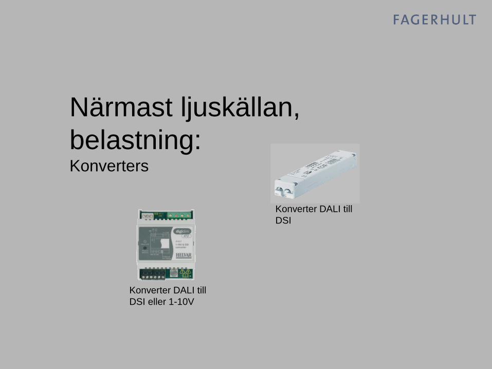
Närmast ljuskällan,
belastning:Konverters
Konverter DALI till
DSI eller 1-10V
Konverter DALI till
DSI

Närmast ljuskällan,
belastning:Transformatorer
Exempel på DALI
transformator

För övrig belastning:Reläenhet och motorstyrenhet
Reläenhet 4
reläer
Motorstyrenhet
2 motorer

Påverkande enheter:Paneler och ingångsmoduler
Programmerbar
ingångsenhet med
4 funktioner
Ingångsenhet med
4 funktionerTryckknappspanel
4 scenarier, upp/ner
samt från.
Enheten har även
IR-mottagare

IR sändare
Påverkande enheter:IR-sändare och Multisensor
Multisensor

DALI Easy
T5 tubes
Max. 16 ECG

DALI I
PRAKTIKEN

Säker anslutning
3

EXEMPEL 1

Belastning 1 Belastning 2 Belastning 3
125200
Belastning 4
1
34
2
303

•All belastning regleras gemensamt
•Fyra nivåer på panel 125
•IR-sändare

EXEMPEL 2

Belastning 1 Belastning 2 Belastning 3
125200
Belastning 4

•Anslut datorns programvara
DIGIDIM
•Belastning regleras individuellt
•Fyra ljusscener på panel 125
•Namnge belastningar och paneler

EXEMPEL 3

Belastning 1 Belastning 2 Belastning 3
125200
Belastning 4
121200
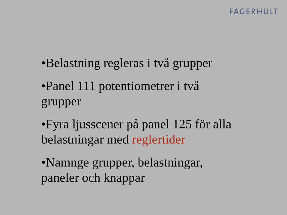
•Belastning regleras i två grupper
•Panel 111 potentiometrer i två
grupper
•Fyra ljusscener på panel 125 för alla
belastningar med reglertider
•Namnge grupper, belastningar,
paneler och knappar

EXEMPEL 4

Belastning 1 Belastning 2 Belastning 3
125200
Belastning 4
121200

•Programmera scen 14, 15
•PIR tider
•Manuell till automatisk från
•Last level på belastningar

Vidare övningar:
•Konstantljus
•Ändring av panelfunktioner, delad
panel m.m.
•Låsning av funktioner
•Virtuella enheter

ROUTER SYSTEM


FRÅGOR
?

Kan DALI enheter förlora minnet ?
Nej.
Minnet är s.k. flashminne. All
information är lagrad även om
enheten är bortkopplad från nät
eller DALI system.

Vad händer om DALI kontrollspänning försvinner ?
Basinställningen i alla DALI
belastningar är att reglera ljuset till
100%.
Detta kan senare ändras till andra
ljusnivåer.

Varför kallas DALI inte för ett bussystem ?
Bus system betecknas av högre
överföringshastighet och större
programmeringsmöjlighet.
DALI ansluter till Bus system, och
använder liknade funktioner
anpassade och förenklade för
belysning.

•Hur etablerat är DALI idag ? Installationer ?
En av anledningen till detta
seminare är att informera om DALI
och dess betydelse för framtida
belysningsinstallationer.

•Måste man “starta upp” ett DALI system?
Nej.
Alla enheter är förberedda på att
svara till Broadcast kommandon,
som reglerar alla enheter
gemensamt.
Detta kan användas som ett
funktionstest inför senare
programmering

•Behöver man en dator för att programmera installationen?
Nej.
Vissa basfunktioner och
grupperingar kan göras med
tryckknappar eller fjärkontroller av
olika fabrikat. Detta kan vara lagom
för en mindre installation.
Vid mer detaljerade funktioner är
dator ett bra och lätt verktyg för
konfigurering av ett DALI system

•Är kontrollsystemen en del av DALI standarden?
Nej.
Styrsystem av olika fabrikat har
olika funktioner och uppbyggnad.
Man skall använda ett
kontrollsystem i en DALI
installation, men man kan bland hf-
don avsedda för DALI.

•Kan jag reglera mer än lysrör? Andra ljuskällor?
Ja.
Det finns dimmrar, transformatorer,
reläenheter m.m. för olika
belastningar

•Varför behövs en strömförsörjning?
Alla DALI-anslutna enheter måste
känna av den spänning som
kommunikationen sänds över. En
viss ström används dessutom till
dioder i tryckknappspaneler m.m.
