ballistic performance of composite metal foams -...
TRANSCRIPT
Accepted Manuscript
Ballistic Performance of Composite Metal Foams
Matias Garcia-Avila, Marc Portanova, Afsaneh Rabiei
PII: S0263-8223(15)00043-4
DOI: http://dx.doi.org/10.1016/j.compstruct.2015.01.031
Reference: COST 6161
To appear in: Composite Structures
Please cite this article as: Garcia-Avila, M., Portanova, M., Rabiei, A., Ballistic Performance of Composite Metal
Foams, Composite Structures (2015), doi: http://dx.doi.org/10.1016/j.compstruct.2015.01.031
This is a PDF file of an unedited manuscript that has been accepted for publication. As a service to our customers
we are providing this early version of the manuscript. The manuscript will undergo copyediting, typesetting, and
review of the resulting proof before it is published in its final form. Please note that during the production process
errors may be discovered which could affect the content, and all legal disclaimers that apply to the journal pertain.

1
Ballistic Performance of Composite Metal Foams
Matias Garcia-Avila1, Marc Portanova
2, Afsaneh Rabiei
1*
1 Advanced Materials Research Lab, Department of Mechanical and Aerospace Engineering,
North Carolina State University, Raleigh, USA
2 Aviation Applied Technology Directorate (AATD), U.S. Army Research, Development &
Engineering Center, Fort Eustis, USA
Abstract
The application of advance materials to manufacture hard armor systems has led to high
performance ballistic protection. Due to its light-weight and high impact energy absorption
capabilities, Composite Metal Foams have shown good potential for applications as ballistic
armor. A high-performance light-weight composite armor system has been manufactured using
boron carbide ceramics as the strike face, composite metal foam processed by powder metallurgy
technique as a bullet kinetic energy absorber interlayer, and aluminum 7075 or KevlarTM
panels
as backplates with a total armor thickness less than 25 mm. The ballistic tolerance of this novel
composite armor system has been evaluated against the 7.62x51 mm M80 and 7.62x63 mm M2
armor piercing projectiles according to U.S. National Institute of Justice (NIJ) standard 0101.06.
The results showed that composite metal foams absorbed approximately 60-70% of the total
kinetic energy of the projectile effectively and stopped both types of projectiles with less depth
of penetration and backplate deformation than that specified in the NIJ 0101.06 standard
guidelines. Finite element analysis was performed using Abaqus/Explicit to study the failure
mechanisms and energy absorption of the armor system. The results showed close agreement
between experimental and analytical results.
Keywords: Composite Metal Foam, dynamic loading, hollow spheres, powder metallurgy,
ballistics, finite element analysis
*Corresponding author: Dr. Afsaneh Rabiei
Department of Mechanical and Aerospace Engineering

2
North Carolina State University
911 Oval Drive, Campus Box 7910
Raleigh, NC, 27695, USA
Tel.: 919-513-2674
Fax.: 919-515-7968
E-mail address: [email protected]
1. Introduction
High-performance hard armor systems for ballistic protection of aircraft, ground and amphibious
vehicles, and personnel have always been the subject of study for researchers. Hard armor
systems typically consists of multiple layers, with a ceramic or ceramic composite plate at the
strike face, backed with a ductile material such as ballistic steel or aluminum, or a high
performance fiber reinforced composite. This hybrid arrangement of layers allows the armor
system to defeat the projectile upon impact, with the ceramic layer blunting and eroding the
projectile due to its high hardness, and the more ductile/high tensile backing plate absorbing the
residual kinetic energy of the fractured or deformed projectile through plastic deformation [1]. A
variety of armor options are already available, however each one has its own limitations
restricting their widespread use in many applications. The development of light-weight combat
technology, such as aircraft and amphibious vehicles, and the need to improve higher mobility
for ground troops requires the continuous reduction of armor weight while increasing their
ballistic performance.
Composite armors made with ceramic strike face and high-strength fiber reinforced composites
have been widely studied as light-weight armors in the past. Several types of ceramic materials,
such as aluminum oxide (Al2O3), boron carbide (B4C), silicon carbide (SiC), silicon nitride
(Si3N4), and combinations of those are typically used as the strike face plate in armor systems [2-
6]. These ceramics are combined with high-tensile strength back plates made of aramid fiber

3
composites such as KevlarTM
and TwaronTM
, or polyethylene composites such as SpectraTM
or
DyneemaTM
to absorb the kinetic energy of the projectile. Although some of these combinations
perform to some extent, the high cost of the constituents along with their heavy weight leaves
room for improvement.
Composite Metal Foam (CMF) is low-weight high-strength metal foam manufactured using
hollow metallic spheres embedded in a solid metal matrix. This material has shown superior
mechanical properties compared to any other metal foam [7-15]. These outstanding qualities of
CMFs are further improved under high-speed impact type of loading (similar to that in ballistic
impact) compared to quasi-static loading [16]. These properties have made composite metal
foams strong candidates for applications in composite armor systems. In this paper, CMF
manufactured with 2 mm steel hollow spheres, embedded in a stainless steel matrix, and
processed using powder metallurgy technique, was used to fabricate a new light-weight high
performance composite armor system. The CMF was bonded to a ceramic plate on the strike
face. Some samples were tested without any backing plates and some used a thin layer of
aluminum or KevlarTM
backplate behind the CMF. Ballistic testing was performed using U.S.
National Institute of Justice (NIJ) standard 0101.06 [17] for 7.62x51 mm M80 (Type III) and
7.62x63 mm M2 Armor Piercing (AP) (Type IV) threats.
A finite element approach was used to simulate ballistic impact and predict the energy absorbed
by the Composite Metal Foam (CMF) layer within the composite armor system. A full 3D
model of the composite armor was studied using a Lagrangian formulation in Abaqus/Explicit
16.3 commercial solver.
4
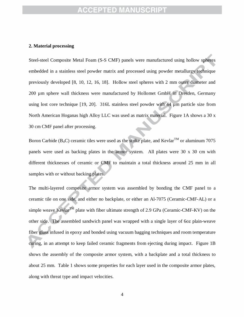
2. Material processing
Steel-steel Composite Metal Foam (S-S CMF) panels were manufactured using hollow spheres
embedded in a stainless steel powder matrix and processed using powder metallurgy technique
previously developed [8, 10, 12, 16, 18]. Hollow steel spheres with 2 mm outer diameter and
200 µm sphere wall thickness were manufactured by Hollomet GmbH in Dresden, Germany
using lost core technique [19, 20]. 316L stainless steel powder with 44 µm particle size from
North American Hoganas high Alloy LLC was used as matrix material. Figure 1A shows a 30 x
30 cm CMF panel after processing.
Boron Carbide (B4C) ceramic tiles were used as the strike plate, and KevlarTM
or aluminum 7075
panels were used as backing plates in the armor system. All plates were 30 x 30 cm with
different thicknesses of ceramic or CMF to maintain a total thickness around 25 mm in all
samples with or without backing plates.
The multi-layered composite armor system was assembled by bonding the CMF panel to a
ceramic tile on one side, and either no backplate, or either an Al-7075 (Ceramic-CMF-AL) or a
simple weave KevlarTM
plate with fiber ultimate strength of 2.9 GPa (Ceramic-CMF-KV) on the
other side. The assembled sandwich panel was wrapped with a single layer of 6oz plain-weave
fiber glass infused in epoxy and bonded using vacuum bagging techniques and room temperature
curing, in an attempt to keep failed ceramic fragments from ejecting during impact. Figure 1B
shows the assembly of the composite armor system, with a backplate and a total thickness to
about 25 mm. Table 1 shows some properties for each layer used in the composite armor plates,
along with threat type and impact velocities.

5
3. Ballistic Experiments
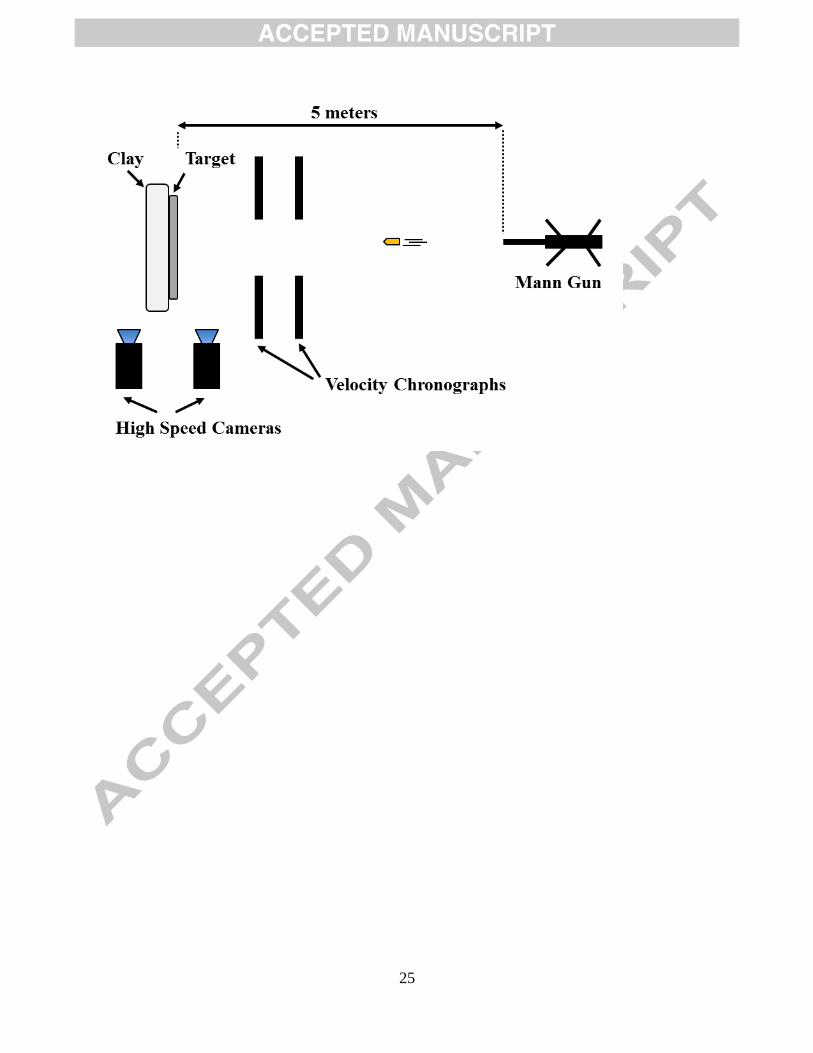
Ballistic testing of the composite armor system was performed using the guidelines included in
the National Institute of Justice (NIJ) standard 0101.06 [17] for Type III (7.62x51 mm M80) and
Type IV (7.62x63 mm M2 AP) threats. Figure 2 shows a top view sketch of the setup for the
ballistic experiments. The composite armor system was placed against a heated Roma Plastilina
No. 1 (clay), following the standard guidelines, in order to monitor the total out of plane
deformation of the back of the armor, which is an indication of the potential body trauma caused
by the impact. To prevent serious injury, NIJ 0101.06 specifies a maximum of 44 mm for the
depth of penetration (DOP) into the clay and no limit on the diameter of the footprint, or back
face signature (BFS). A “Mann” gun mounted on a two axis rig was used for the ballistic tests.
Accurate measurements of the projectile speeds were possible using two velocity chronographs
located between the gun and the target. Two high speed cameras were aimed at the impact face
and the rear of the target to monitor the impacts. A 5 m distance was maintained between the
gun and the target with a zero angle of obliquity the gun.
4. Finite Element Analysis
Studying the behavior of the armor system under ballistic impact using finite element analysis
(FEA) provides an understanding of the failure mechanisms and a powerful and inexpensive tool
for optimization of the ballistic system.
Hydrocodes are computer programs which handle propagation of shock waves, stress, strain,
velocities, etc. within a continuum material as a function of time and position [21]. The
relationship between these changes in the material state can be calculated using classical
continuum mechanics such as conservation of mass, momentum, and energy. There are two
6
major types of hydrocodes descriptions to create a system of differential equations, Lagrangian
and Eulerian. To solve these equations, material properties are used to relate stress and strain
and define failure mechanisms within the material, and equations of state relate internal energy
and density changes with internal pressure [21]. Typically, Lagrangian solutions are simpler and
require fewer equations to be solved than that of Eulerian definitions, thus requiring less
computing power. For this reason, Lagrangian descriptions are preferred to solve the majority of
finite element models.
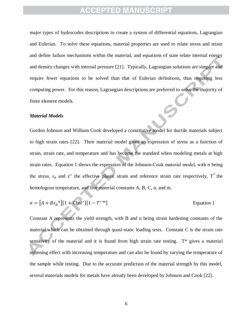
Material Models
Gordon Johnson and William Cook developed a constitutive model for ductile materials subject
to high strain rates [22]. Their material model gives an expression of stress as a function of
strain, strain rate, and temperature and has become the standard when modeling metals at high
strain rates. Equation 1 shows the expression of the Johnson-Cook material model, with σ being
the stress, εp and the effective plastic strain and reference strain rate respectively, T*
the
homologous temperature, and five material constants A, B, C, n, and m.
Equation 1
Constant A represents the yield strength, with B and n being strain hardening constants of the
material which can be obtained through quasi-static loading tests. Constant C is the strain rate
sensitivity of the material and it is found from high strain rate testing. T* gives a material
softening effect with increasing temperature and can also be found by varying the temperature of
the sample while testing. Due to the accurate prediction of the material strength by this model,
several materials models for metals have already been developed by Johnson and Cook [22].

7
The behavior of ceramic face plate and the bullet has already been studied by other researchers
[23, 24]. The purpose of this FEA analysis is to study the behavior and energy absorption of
Composite Metal Foams at high-speed impacts. As a result, the focus of this study is on the
behavior of CMF with the assumption that the ceramic failure has already taken place and the
bullet has already been blunted. Although this model does not include the complete behavior of
the armor system, it can serve as a parametric tool to understand the behavior of the composite
foam and the aluminum backing plate as a coupled system.
Composite Metal Foam (CMF) has unique material properties that are not easy to fit into any
preexisting constitutive material model. Typical stress-strain curve under quasi-static
compression for S-S CMF manufactured using 2 mm spheres and powder metallurgy technique
is shown in Figure 3. Similar to all metallic foams, steel-steel composite metal foam is
characterized by an elastic region, followed by a yield and a plateau region. During the
“plateau” region, the porosities continue collapsing under compression, until all porosities are
collapsed and the material starts behaving like a solid material. In the case of composite metal
foams the presence of a matrix between spheres causes a strain hardening effect during the
period in which spheres are collapsing, which is seen as a tilted plateau in the stress-strain curve
shown in Figure 3. Further details about the typical stress-strain curves of CMFs under
compression can be found elsewhere [7, 9]. When loading S-S CMF under high strain
conditions, the material exhibits an increase in yield strength due to the inertial effects and
cushioning effect caused by the compression of the air trapped in the porosities [16, 25, 26].
This effect is observed in Figure 3 by the dotted curve corresponding to the dynamic behavior of
steel composite foams at a strain rate of 3277 1/s tested in a using Hopkinson Bar system.
Further details related to that experiment and resulted data are presented elsewhere [25]. The
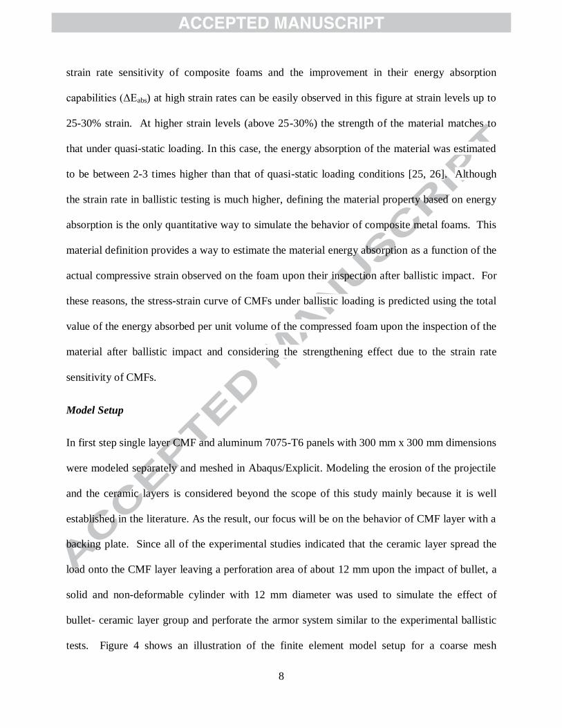
8
strain rate sensitivity of composite foams and the improvement in their energy absorption
capabilities (ΔEabs) at high strain rates can be easily observed in this figure at strain levels up to
25-30% strain. At higher strain levels (above 25-30%) the strength of the material matches to
that under quasi-static loading. In this case, the energy absorption of the material was estimated
to be between 2-3 times higher than that of quasi-static loading conditions [25, 26]. Although
the strain rate in ballistic testing is much higher, defining the material property based on energy
absorption is the only quantitative way to simulate the behavior of composite metal foams. This
material definition provides a way to estimate the material energy absorption as a function of the
actual compressive strain observed on the foam upon their inspection after ballistic impact. For
these reasons, the stress-strain curve of CMFs under ballistic loading is predicted using the total
value of the energy absorbed per unit volume of the compressed foam upon the inspection of the
material after ballistic impact and considering the strengthening effect due to the strain rate
sensitivity of CMFs.
Model Setup
In first step single layer CMF and aluminum 7075-T6 panels with 300 mm x 300 mm dimensions
were modeled separately and meshed in Abaqus/Explicit. Modeling the erosion of the projectile
and the ceramic layers is considered beyond the scope of this study mainly because it is well
established in the literature. As the result, our focus will be on the behavior of CMF layer with a
backing plate. Since all of the experimental studies indicated that the ceramic layer spread the
load onto the CMF layer leaving a perforation area of about 12 mm upon the impact of bullet, a
solid and non-deformable cylinder with 12 mm diameter was used to simulate the effect of
bullet- ceramic layer group and perforate the armor system similar to the experimental ballistic
tests. Figure 4 shows an illustration of the finite element model setup for a coarse mesh

9
definition. Quadratic tetrahedral elements were used for all bodies and the model was
constrained using a fixed support at the outside edges of the plates, as suggested in the literature
[23, 24, 27-29]. The model setup shown in Figure 4 corresponds to the coarse mesh definition,
with large elements at the outside of the panel and a progressive finer mesh at the center of the
panel. In order to obtain accurate results under bending, up to 3 elements were considered
through the thickness of the aluminum layer in the coarser mesh definition. Smaller elements
were considered for the finer mesh definition. Larger elements at the outside, where bending
was not observed, should not affect the results at large.
The ballistic clay is considered to have a yield strength of 1 MPa with an elastic-perfectly plastic
behavior. A pressure of 1MPa was considered as a support boundary condition on the back of the
aluminum plate to simulate the resistance provided by the clay during the ballistic tests.
Frictionless contact definition was defined for all surfaces [27] and general contact definitions
were considered between all elements, in agreement with the literature [23, 27, 28]. Lagrangian
formulation was used to solve the conservation equations. The energy absorbed by each panel
was obtained from the simulation and compared to the experimental tests.
Material Model Definitions
Due to the complexity of the composite armor system, several material constitutive models were
considered for each layer material:
Aluminum 7075-T6 backing plate: a Johnson-Cook constitutive material model was considered
for the aluminum backing plates used in the composite armor with the parameters [30] shown in
Table 2.

10
Steel-Steel Composite Metal Foam: in order to maintain the shape of the stress-strain curve
shown in Figure 3 as a qualitative criterion under high-strain rate loading, a multi-linear stress-
strain definition is used in the model to define the material response and shown in Figure 5. Our
previous studies indicated that the CMFs exhibit a strengthening effect due to the strain rate
sensitivity of CMFs (Figure 3) [25]. In this study, the energy absorbed per unit volume of CMF
under ballistic impacts in experimental studies [26] is used to estimate the values of the yield and
plateau strength. The density of the material is considered 2.8 g/cm3, with an elastic modulus of
13.2 GPa and Poisson ratio of 0.1.
To minimize mesh size dependence of the FEA results, three different mesh sizes of coarse,
medium, and fine were used to simulate penetration impact on an aluminum backing plate. Since
the load would be applied at the center of the plate, a center area of the plate of 100 mm in
diameter was meshed using smaller elements. For the coarse, medium, and fine meshes, the
center area was meshed using 2, 0.9, and 0.7 mm maximum size elements and the outer area
used 15, 10, and 9 mm maximum size elements respectively.
5. Results and discussion
Experimental Results
All various types of samples without backplates and with KevlarTM
or Al backplates were able to
stop the projectiles with DOPs less than 44 mm, which is considered the maximum allowable
penetration according to the NIJ 0101.06 standard.
Digital images of the front strike face and rear face of a Ceramic-CMF (no backing) armor panel
after NIJ-Type III impact test are shown in Figure 6A-B respectively. The combination of
ceramic and S-S CMF showed superior ballistic performance under Type III threats at impact
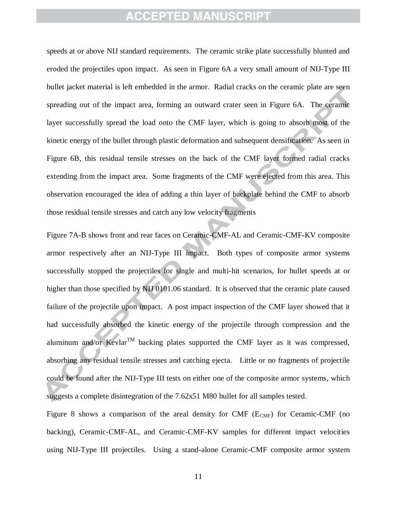
11
speeds at or above NIJ standard requirements. The ceramic strike plate successfully blunted and
eroded the projectiles upon impact. As seen in Figure 6A a very small amount of NIJ-Type III
bullet jacket material is left embedded in the armor. Radial cracks on the ceramic plate are seen
spreading out of the impact area, forming an outward crater seen in Figure 6A. The ceramic
layer successfully spread the load onto the CMF layer, which is going to absorb most of the
kinetic energy of the bullet through plastic deformation and subsequent densification. As seen in
Figure 6B, this residual tensile stresses on the back of the CMF layer formed radial cracks
extending from the impact area. Some fragments of the CMF were ejected from this area. This
observation encouraged the idea of adding a thin layer of backplate behind the CMF to absorb
those residual tensile stresses and catch any low velocity fragments
Figure 7A-B shows front and rear faces on Ceramic-CMF-AL and Ceramic-CMF-KV composite
armor respectively after an NIJ-Type III impact. Both types of composite armor systems
successfully stopped the projectiles for single and multi-hit scenarios, for bullet speeds at or
higher than those specified by NIJ 0101.06 standard. It is observed that the ceramic plate caused
failure of the projectile upon impact. A post impact inspection of the CMF layer showed that it
had successfully absorbed the kinetic energy of the projectile through compression and the
aluminum and/or KevlarTM
backing plates supported the CMF layer as it was compressed,
absorbing any residual tensile stresses and catching ejecta. Little or no fragments of projectile
could be found after the NIJ-Type III tests on either one of the composite armor systems, which
suggests a complete disintegration of the 7.62x51 M80 bullet for all samples tested.
Figure 8 shows a comparison of the areal density for CMF (ECMF) for Ceramic-CMF (no
backing), Ceramic-CMF-AL, and Ceramic-CMF-KV samples for different impact velocities
using NIJ-Type III projectiles. Using a stand-alone Ceramic-CMF composite armor system

12
yielded successful results against Type III threats up to speeds at or above the NIJ standard
requirements. A previous study by the authors suggested an increase on the yield strength of
CMF material at high strain rates by over a factor of 2 at impact speeds up to 26 m/s [16]. In
addition, a preliminary study of the ballistic properties of CMF suggested an energy absorption
increase between 2-3 times higher at NIJ-Type III and IV impact speeds [31]. This increase in
performance of CMF at high loading rates suggested a possible reduction in thickness of the
ceramic and CMF layers, resulting in lighter and thinner armor plates. Also, adding Aluminum
or KevlarTM
backing plates to the back of the CFM allowed a reduction of the thickness of both
ceramic and CMF, which resulted in a weight reduction of 17% compared to the no backing
samples.
Similarly, Figure 9A-B shows front and rear faces of Ceramic-CMF-AL and Ceramic-CMF-KV
composite armor respectively after impact of NIJ-Type IV projectiles. As can be seen, similar
behavior of the armor system was obtained for Type IV projectiles. In this case, the partially
disintegrated the hardened steel core and part of the bullet jacket were left embedded in the
armor, as shown in Figure 10A. The AP projectiles tested on the Ceramic-CMF-AL and
Ceramic-CMF-KV showed 40-65% mass loss at impact velocities between 860-890 m/s (Figure
10B), depending on the thickness of the ceramic.
Areal density for CMF (ECMF) versus projectile speed for NIJ-Type IV tests are shown in Figure
11 for Ceramic-CMF (no backing), Ceramic-CMF-AL, and Ceramic-CMF-KV composite
armors. For the Ceramic-CMF-AL, and Ceramic-CMF-KV composite armor systems designed
for NIJ-Type IV threats, the addition of the backing plate and the reduction in thickness of
ceramic and CMF layers resulted in a 13% and 20% weight reduction respectively compared to

13
the Ceramic-CMF armor, with the KV backed samples being 5% lighter than the AL backed
samples due to a thinner ceramic layer used.
Figure 12 illustrates the deformation mechanism of a Ceramic-CMF-backing plate composite
armor system. As discussed before, upon impact, the hard ceramic plate blunts the projectile due
to large compressive stresses developed at the projectile tip. When the compressive stresses
travel through the ceramic layer and reach the interface between ceramic and CMF layer, tensile
stresses are created due to the sudden change in mechanical impedance between the two layers.
These tensile stressed are then reflected back towards the impact face. The intersection between
the compressive and tensile stress waves traveling through the ceramic layer creates a high stress
concentration area at angles between 25°-75° normal to the outer surface of the ceramic, which
results in the failure of the ceramic material forming a Hertzian cone zone [32]. This cone
detaches from the ceramic and serves to distribute the compressive load at the ceramic-CMF
interface over a larger area. The residual tensile waves in the ceramic form circumferential and
radial cracks and due to this localized fracture and comminution in the vicinity of the impact
area, results in an outward crater at the impact face. As penetration progresses, compressive
waves build up on the CMF layer until its yield point and further, deforming plastically at high
compressive loads and absorbing the kinetic energy of the projectile. The light weight backing
plate below the CMF layer absorbs any residual tensile stresses of the armor system, maintaining
the integrity of the impact area and keeping debris contained inside the perforation. Using a
combination of ceramic, CMF, and backing plate, provides a layer-based functional design
solution where each constituent contributes in a collaborative fashion to the ballistic energy
absorption process

14
In ballistic impacts, most of the kinetic energy of the projectile is transformed into brittle fracture
of the ceramic under compression and tension, plastic deformation of the projectile and backing
plate, and heat. For this study, and since the local temperature at the point of impact could not be
measured, the heat generation is considered negligible for energy calculations. Using an energy
approach previously discussed [31], the energy absorbed by each component in the composite
armor system can be approximated. Upon impact, the kinetic energy of the projectile (EKE) is
transferred to the armor system as the energy used for plastic deformation of the bullet (Ebullet),
energy absorbed by the ceramic (Eceramic), energy absorbed by CMF layer (ECMF), energy
absorbed by the backing plate (Ebacking), and residual energy from clay deformation or debris
ejected from the target in the event of complete penetration (Eres,), as shown in Equation (1):
(1)
Similar studies on energy absorption of armor systems have been reported in the literature [33].
The energy per unit volume of material for the projectile, ceramic, backing plate, and clay can be
calculated from their respective stress-strain curves by calculating the area under the curve using
a strain energy (wp) method according to Equation (2)
(2)
where wp is essentially the area under the stress-strain curve in J/m3. Using material properties of
each layer and multiplying the value of this strain energy by the total amount of material under
deformation per layer (bullet, ceramic, backing plate, clay), the total kinetic energy dispersed by
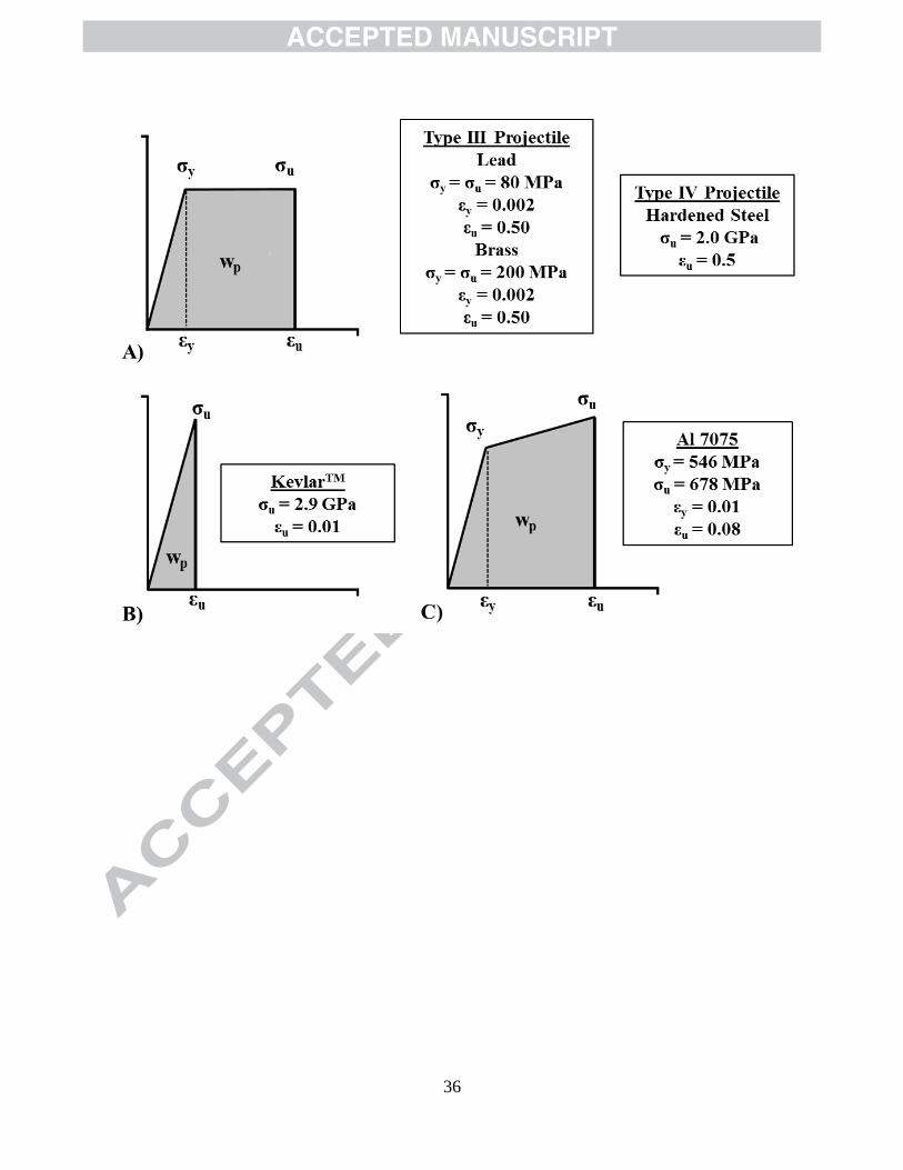
each component of the composite armor system is calculated. Figure 13A-C shows a
representation of each method of calculating strain energy for each layer of the composite armor
against both NIJ-Type III and Type IV projectiles, where σy and εy are the yield strength of the
material and the corresponding strain (for ductile materials), σu and εu are the ultimate strength

15
and corresponding ultimate strain, respectively. Properties of each component are obtained from
the literature [22, 30, 34] and shown in Figure 13.
Residual energy (Eres) was calculated from BFS and DOP measurements on clay, a σy of 1 MPa,
along with the method shown in Figure 13B, and residual velocities of particles obtained from
high speed video.
Solving for ECMF in equation 1 and substituting all energy values calculated gives the estimated
energy absorption by the CMF layer. Values for all energy absorbed per layer in percentage of
total kinetic energy are shown in Table 3.
Figure 14 shows the kinetic energy absorbed by the CMF layer in the composite armor system
for both NIJ-Type III and Type IV tests. As can be seen, with the appropriate arrangement of
layers, CMF was capable of absorbing 60-70% of the kinetic energy of the bullet, proving the
superior energy absorption capabilities of composite metal foams at high impact speeds. It is
also observed that by adding a soft backing plate behind CMF, the areal density was decreased
with no adverse effect on the energy absorption capabilities of the total composite armor system.
Finite Element Analysis Results
Mesh Sensitivity Study
The penetrator’s net nodal force reactions were obtained and plotted against projectile
displacement for a depth of penetration of 20 mm (such DOP is selected based on our ballistic
studies) (Figure 15). No issues were encountered with over skewed elements for the 2 finer
mesh definitions. It can be seen that the solution for both medium and fine meshes is
comparable and a finer mesh does not provide a more accurate solution. For this reason, and to
save on computing power, a medium mesh definition was used in the model.

16
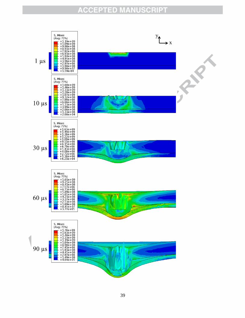
Von-Mises stress plots for a 15.17 mm depth of penetration simulation are shown in Figure 16 at
10, 30, 60, and 90 µs of penetration time. Compression of the CMF layer at 90 µs shows full
densification up to 80% strain, with similar deformation pattern obtained in experimental tests.
The aluminum backplate supports the rear face of the CMF, and deforms in tension absorbing the
residual kinetic energy of the penetrator, leaving a bulging profile on the armor system similar to
that shown in Figure 7A and Figure 9A.
Figure 17 shows the simulation results for energy absorbed by CMF and aluminum layers for
both Type III and Type IV bullet speeds compared to the experimental results. As can be seen, a
close prediction of the energy dissipated by the aluminum plate is obtained for all tests. For the
CMF layer, an over-prediction of the energy absorbed by the FEA model is seen in Figure17.
Figure 18 shows the high x-y shear stresses developed in the CMF layer under puncture by the
penetrator. These shear stresses could cause failure in the material and could hinder plastic flow
under ballistic loading, artificially raising the energy absorption of the material in the FEA
model. However, behavior of CMF under shear loading has not been studied extensively and as
the result it was not taken into account in this material model. Although close prediction of the
behavior of CMF has been obtained by this model, further characterization of CMF under shear
loading is needed to consider complete material failure definitions and develop a more accurate
model.
6. Conclusions
Composite metal foam panels manufactured using 2 mm steel hollow spheres embedded in a
stainless steel matrix and processed through powder metallurgy technique were used together
with boron carbide ceramic and aluminum 7075 or KevlarTM
back panels to fabricate a new
composite armor system. This composite armor was tested against NIJ-Type III and Type IV

17
threats using NIJ 0101.06 ballistic test standard. The highly functional layer-based design
allowed the composite metal foam to absorb the ballistic kinetic energy effectively, where the
CMF layer accounted for 60-70% of the total energy absorbed by the armor system, and allowed
the composite armor system to show superior ballistic performance for both Type III and IV
threats.
Finite element analysis results for ballistic loading of the armor system closely predicted the
behavior and energy absorption of the CMF and aluminum layers. The Kevlar system was not
considered in the simulation since the results for the energy absorbed by CMF in the system with
the aluminum layer were successful. However, the failure mechanisms of CMF under ballistic
loading are complex and further characterization of the material under shear loading is necessary
prior to establish a comprehensive model of its behavior under ballistic loading.
Acknowledgments
The authors would like to acknowledge North Carolina State University’s Chancellor Innovation
Fund (CIF) for its financial support that made this project possible. Special thanks to Dr. Robert
Bryant and his team at the Advanced Materials and Processing Branch at NASA Langley
Research Center, for granting access to their material processing facilities.
18
References
[1] Hetherington J, Smith P. Blast and Ballistic Loading of Structures. Oxford ; Boston: CRC
Press; 1994.
[2] Medvedovski E. Ballistic performance of armour ceramics: Influence of design and structure.
Part 1. Ceram Int 2010;36:2103–15.
[3] Medvedovski E. Ballistic performance of armour ceramics: Influence of design and structure.
Part 2. Ceram Int 2010;36:2117–27.
[4] David NV, Zheng JQ, Gao X-L. Ballistic Resistant Body Armor: Contemporary and
Prospective Materials and Related Protection Mechanisms. Appl Mech Rev 2009;62:050802–
050802.
[5] Tasdemirci A, Tunusoglu G, Güden M. The effect of the interlayer on the ballistic
performance of ceramic/composite armors: Experimental and numerical study. Int J Impact Eng
2012;44:1–9.
[6] Medvedovski E. Lightweight ceramic composite armour system. Adv Appl Ceram
2006;105:241–5.
[7] Rabiei A, O’Neill AT. A study on processing of a composite metal foam via casting. Mater
Sci Eng A 2005;404:159–64. doi:10.1016/j.msea.2005.05.089.
[8] Neville BP, Rabiei A. Composite metal foams processed through powder metallurgy. Mater
Des 2008;29:388–96.
[9] Vendra LJ, Rabiei A. A study on aluminum–steel composite metal foam processed by
casting. Mater Sci Eng A 2007;465:59–67.

19
[10] Rabiei A, Vendra LJ. A comparison of composite metal foam’s properties and other
comparable metal foams. Mater Lett 2009;63:533–6.
[11] Vendra L, Rabiei A. Evaluation of modulus of elasticity of composite metal foams by
experimental and numerical techniques. Mater Sci Eng A 2010;527:1784–90.
[12] Rabiei A, Neville B, Reese N, Vendra L. New Composite Metal Foams under Compressive
Cyclic Loadings. Mater Sci Forum 2007;539-543:1868–73.
[13] Vendra L, Neville B, Rabiei A. Fatigue in aluminum–steel and steel–steel composite foams.
Mater Sci Eng A 2009;517:146–53.
[14] Vendra LJ, Brown JA, Rabiei A. Effect of processing parameters on the microstructure and
mechanical properties of Al–steel composite foam. J Mater Sci 2011;46:4574–81.
[15] Brown JA, Vendra LJ, Rabiei A. Bending Properties of Al-Steel and Steel-Steel Composite
Metal Foams. Metall Mater Trans A 2010;41:2784–93.
[16] Rabiei A, Garcia-Avila M. Effect of various parameters on properties of composite steel
foams under variety of loading rates. Mater Sci Eng A 2013;564:539–47.
[17] NIJ 0101.06-U.S. Department of Justice. Ballistic Resistance of Body Armor NIJ Standard
0101.06 2008.
[18] Rabiei A, Vendra L, Reese N, Young N, Neville BP. Processing and characterization of a
new composite metal foam. Mater Trans 2006;47:2148–53.
[19] Andersen O, Waag U, Schneider L, Stephani G, Kieback B. Novel Metallic Hollow Sphere
Structures. Adv Eng Mater 2000;2:192–5.

20
[20] Stephani G, Kupp D, Claar TD, Waag U. Fabrication of Ti-based components with
controlled porosity. Int Conf Powder Metall Part Mater 2001:50–8.
[21] Anderson Jr. CE. An overview of the theory of hydrocodes. Int J Impact Eng 1987;5:33–59.
[22] Johnson GR, Cook WH. A constitutive model and data for metals subjected to large strains,
high strain rates and high temperatures. Proc 7th Int Symp Ballist 1983;21:541–7.
[23] Bürger D, Rocha de Faria A, de Almeida SFM, de Melo FCL, Donadon MV. Ballistic
impact simulation of an armour-piercing projectile on hybrid ceramic/fiber reinforced composite
armours. Int J Impact Eng 2012;43:63–77.
[24] Feli S, Asgari MR. Finite element simulation of ceramic/composite armor under ballistic
impact. Compos Part B Eng 2011;42:771–80.
[25] Rabiei A. Material with Improved Absorption of Collision Forces for Railroad Cars. Safety
IDEA Project 20 final report, National Academy of Science 2014.
[26] Garcia-Avila M, Portanova M, Rabiei A. Ballistic Performance of a Composite Metal
Foam-Ceramic Armor System. Proc Metfoam 2013 2013.
[27] Iqbal MA, Chakrabarti A, Beniwal S, Gupta NK. 3D numerical simulations of sharp nosed
projectile impact on ductile targets. Int J Impact Eng 2010;37:185–95.
[28] Vanichayangkuranont T, Maneeratan K, Chollacoop N. Numerical simulation of level 3A
ballistic impact on ceramic/steel armor. The 20th Conference of Mechanical Engineering
Network of Thailand 2006.

21
[29] Teng X, Wierzbicki T, Huang M. Ballistic resistance of double-layered armor plates.
Twenty-Fifth Anniv Celebr Issue Honouring Profr Norman Jones His 70th Birthd 2008;35:870–
84.
[30] Brar NS, Joshi VS, Harris BW. Constitutive Model Constants for Al7075-T651 and Al7075-
T6. Am. Inst. Phys. Conf. Ser., vol. 1195, 2009, p. 945–8.
[31] Garcia-Avila M, Portanova M, Rabiei A. Ballistic Performance of a Composite Metal
Foam-Ceramic Armor System. Proc Metfoam 2013 2013.
[32] Fountzoulas CG, LaSalvia JC. Improved Modeling and Simulation of the Ballistic Impact of
Tungsten-Based Penetrators on Confined Hot-Pressed Boron Carbide Targets. In: Swab JJ,
Halbig M, Sanjaythur, editors. Adv. Ceram. Armor VIII, John Wiley & Sons, Inc.; 2012, p. 209–
17.
[33] Naik NK, Kumar S, Ratnaveer D, Joshi M, Akella K. An energy-based model for ballistic
impact analysis of ceramic-composite armors. Int J Damage Mech 2012:1056789511435346.
[34] L. Peroni MS. Mechanical properties at high strain-rate of lead core and brass jacket of a
NATO 7.62 mm ball bullet 2012;26.
22
Figure 1: A) CMF panel processed using powder metallurgy technique for the application in
armor system and B) schematic of the side cross-section of the complete armor system showing
CMF panel between a B4C ceramic strike plate and a KevlarTM
or Al-7075 backplate
(thicknesses not to scale)
Figure 2: Top view sketch of the ballistic test setup showing gun barrel, bullet velocity
chronograph, target location, and high-speed cameras
Figure 3: Typical stress-strain curves for composite metal foam for quasi-static and dynamic
loading curve [23]
Figure 4: Finite element model setup in Abaqus/Explicit 16.3 showing the mesh for the projectile
(red), CMF layer (yellow) and Aluminum 7075-T6 backplate (green), thicknesses and
dimensions are not in scale.
Figure 5: Multi-linear stress-strain definition used for S-S CMF at ballistic relative strain rates
Figure 6: Digital images of a Type III impact area on an armor system without backing plate: A)
front strike face showing complete arrest of the bullet and B) rear face showing bulging of CMF
and small amount of cracking due to tensile stresses
Figure 7: Front-strike and rear face digital images of impact area of NIJ-Type III tests showing
complete arrest of the bullet and rear bulging of backing plate for: A) Ceramic-CMF-AL, B)
Ceramic-CMF-KV
Figure 8: Areal density for Ceramic-CMF, Ceramic-CMF-AL, and Ceramic-CMF-KV composite
armor tested under Type III conditions at different impact speeds
Figure 9: Front-strike and rear face digital images of impact area of NIJ-Type IV tests showing
complete arrest of the bullet and rear bulging of backing plate for: A) Ceramic-CMF-AL, B)
Ceramic-CMF-KV
Figure 10: A) NIJ-Type IV AP projectile embedded in a Ceramic-CMF-KV sample after ballistic
test at 865 m/s projectile speed and B) recovered AP projectiles from Ceramic-CMF-KV and
Ceramic-CMF-AL showing 40-65% bullet mass loss
Figure 11: Areal density for Ceramic-CMF, Ceramic-CMF-AL, and Ceramic-CMF-KV
composite armor tested under Type IV conditions at different impact speeds
Figure 12: Representation of the failure mechanism of Ceramic-CMF-Backing plate composite
armor subjected to ballistic loading (thicknesses are not to scale)
Figure 13: Stress-strain curve used for analytical method to calculate plastic strain energy for
each layer with A) corresponding to hardened steel bullet core of NIJ-Type IV projectile and
NIJ-Type III projectile, B) KevlarTM
backing plate, and C) aluminum 7075-T6 backing plate

23
Figure 14: Energy absorbed by CMF layer for both NIJ-Type III and Type IV tests in all
composite armor systems tested
Figure 15: Force-displacement results obtained for a 20 mm DOP simulation for the mesh
sensitivity study for coarse, medium, and fine mesh definitions
Figure 16: Cross-sectional Von-Misses stress contour plots on CMF and Al layer obtained for a
depth of penetration of 15.17 mm at 1, 10, 30, 60, and 90 µs
Figure 17: FEA and analytical results for the energy absorbed by CMF and Al 7075-T6 layers for
both NIJ-Type III and Type IV tests in all composite armor systems tested
Figure 18: Cross-sectional x-y shear plots for a 15.17 depth of penetration simulation, showing
high shear areas on the CMF and aluminum layers

24
25

26

27

28

29

30

31

32

33

34

35
36

37

38
39

40

41

42
Table 1: Some properties of composite armor plates, along with the threat types and impact
velocities
Armor
Thickness (cm)
Areal Density
(g/cm^2) Threat Backing Plate
Mass
Bullet (g)
Impact
Velocity
(m/s)
2.15 5.50 III Aluminum 9.6 841.6
2.15 5.50 III Aluminum 9.6 837.3
2.15 5.50 III Aluminum 9.6 833.6
2.30 5.79 IV Aluminum 10.8 863.2
2.30 5.79 IV Aluminum 10.8 863.8
2.34 5.25 III Kevlar 9.6 843.1
2.34 5.25 III Kevlar 9.6 822.4
2.34 5.25 III Kevlar 9.6 844.9
2.34 5.25 III Kevlar 9.6 842.2
2.34 5.25 III Kevlar 9.6 841.6
2.42 5.52 IV Kevlar 10.8 892.1
2.45 5.50 IV Kevlar 10.8 865.3
2.69 6.53 III No backing 9.6 853.1
2.75 6.78 III No backing 9.6 861.1
2.75 6.78 III No backing 9.6 852.5
2.61 6.69 IV No backing 10.8 869.0
2.69 6.69 IV No backing 10.8 861.7

43
Table 2: Johnson-Cook and elastic material properties for Al7075-T6 plate
Parameter Al7075-T6 [34]
Density (kg/m3) 2800
E (GPa) 72
Poisson’s Ratio (ν) 0.33
Specific Heat (J/kg ˚C) 848
A (MPa) 546
B (MPa) 678
n 0.71
C 0.024
m 1.56
(s-1
) 1.0
Tmelting
(˚C) 650

44
Table 3: Energy absorbed by each layer in the composite armor system as the % of bullet kinetic
energy for both NIJ-Type III and Type IV impacts
Threat Type
Backing Material
Impact Velocity (m/s)
KE (J) % ECMF % Eceramic % Ebacking % Ebullet % Eres
III Al 841.55 3399.41 57.98 7.58 17.94 13.65 0.01
III Al 837.29 3365.03 63.03 7.87 10.13 13.79 0.01
III Al 833.63 3335.69 60.14 7.06 13.68 13.91 0.01
III KV 843.08 3411.74 70.73 11.90 3.75 13.60 0.02
III KV 822.35 3246.05 64.15 17.62 3.91 14.29 0.03
III KV 844.91 3426.55 70.13 13.53 2.77 13.54 0.03
III KV 842.16 3404.34 61.95 15.83 8.53 13.63 0.06
III KV 841.55 3399.41 63.57 16.88 5.85 13.65 0.05
III None 853.15 3493.72 40.16 46.50 na 13.28 0.05
III None 861.07 3558.92 23.53 63.39 na 13.04 0.04
III None 852.54 3488.72 22.24 64.42 na 13.30 0.04
IV Al 863.19 4023.56 56.19 8.46 18.66 19.86 0.01
IV Al 863.80 4029.24 55.57 8.75 20.02 19.84 0.01
IV Al 861.67 4009.36 53.76 8.39 30.17 19.93 0.02
IV KV 892.15 4298.03 68.30 10.96 8.95 11.73 0.06
IV KV 865.33 4043.47 66.00 14.13 7.36 12.47 0.04
IV None 869.00 4077.83 47.13 22.71 na 30.15 0.01
IV None 861.68 4009.46 40.43 28.90 na 30.67 0.01