balsa free c/l racin g w in gs
TRANSCRIPT
"BALSA FREE" C/L RACIN G W IN GSor "a different approach to make a wing using a mould and (almost) no balsa"
by Enrico M AULETTI Jan - 2001
1st PART
THE M O ULD(first part - upper mould)
"Balsa free" wing means (for me) a glassed foam wing made using two devices:
- a two parts mould
- a simple vacuum bagging system.
In my opinion, there are several reasons to think about a "balsa free" wing:
1. Possibility to reach always the same result:
1.1. Profile: if the mould is O K, then all the moulded wing will be O K
1.2. W eight: using "constant density" materials as foam and fibre glass, it will be possible to have (almost) the same
weight
1.3. Stiffness: using "constant properties" materials and a standardised procedure, the final result will be always
the same
2. Possibility to reduce working time (accepting to spend time in the mould preparation)
3. Possibility to avoid balsa dust … and lot of "sanding hours"
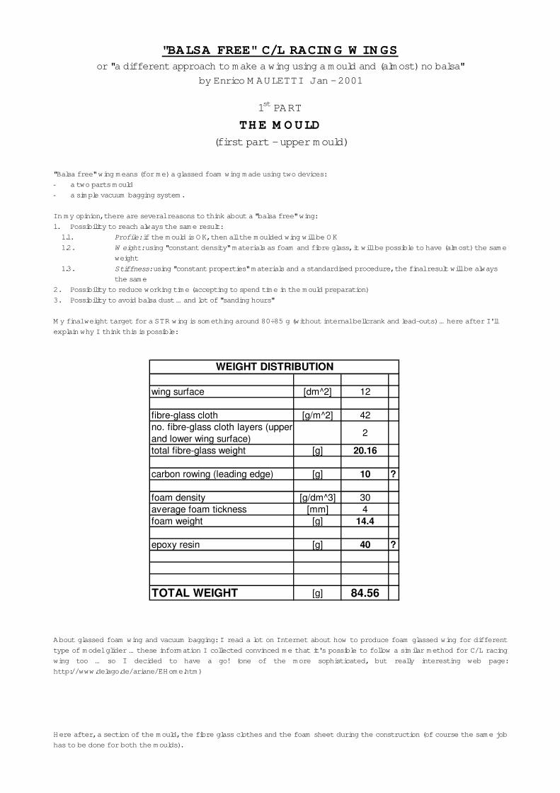
M y final weight target for a STR wing is something around 80÷85 g (without internal bellcrank and lead-outs) … here after I'll
explain why I think this is possible:
About glassed foam wing and vacuum bagging: I read a lot on Internet about how to produce foam glassed wing for different
type of model glider … these information I collected convinced me that it's possible to follow a similar method for C/L racing
wing too … so I decided to have a go! (one of the more sophisticated, but really interesting web page:
http://www.delago.de/ariane/EHome.htm)
Here after, a section of the mould, the fibre glass clothes and the foam sheet during the construction (of course the same job
has to be done for both the moulds).
wing surface [dm^2] 12
fibre-glass cloth [g/m^2] 42no. fibre-glass cloth layers (upperand lower wing surface)
2
total fibre-glass weight [g] 20.16
carbon rowing (leading edge) [g] 10 ?
foam density [g/dm^3] 30average foam tickness [mm] 4foam weight [g] 14.4
epoxy resin [g] 40 ?
TOTAL WEIGHT [g] 84.56
WEIGHT DISTRIBUTION

The basic idea is to use 2 fibre glass cloth layers (one at 90°, the second at 45° for torsional stiffness) for each wing surface
(top and bottom); with the vacuum bagging technology is possible to obtain 2 separated shells, one for each mould, with a very
low resin quantity (that means "light and stiff").
To fill the space between the 2 shells, after the curing of the epoxy used to produce the 2 shells, two 4÷5 mm thick high
density foam sheets are glued to the internal part of both the shells (still inside the moulds); these foam sheets are not shaped
to any profile (just cut with the top view shape of the wing), but just pressed on the internal surface of each shell by the
vacuum.
After curing it is possible to sand (or to cut with an hot wire) the foam in order to have a flat joining surface between the 2
parts of the wing; as reference the flat division surface of the mould is used.
Before joining the 2 parts together it could be possible to put internal leadouts, but for the moment I think to make the first
test with external controls and bellcrank.
At least for the leading edge is possible to make a groove in the foam and to fill it with carbon rows before to join the two
shells.
In this first chapter it's possible to find some pictures and descriptions about the mould construction … this is where I'm now …
in other words: it's possible to follow step by step what I'm trying to do, but I'm not sure at the moment that it will be a
success … of course, I hope so !!!
This is my first attempt in making such a big mould … so surely there will be things that can be improved!
N ote: O f course a trapezoidal wing top view can avoid the necessity of a master wing like these: it's possible to cut a master
using foam, templates and an hot wire or, may be, it's possible to avoid any mould.
This is my STR (you can find it somewhere in the cl_group model plan collection):
As you can see it's trapezoidal … and it's really "different", but it's the best model I never had, believe me!
(I fly C_L racing profile models since 1978 …I stopped my activity for ~15 years and now I'm back since 4 years ◊ 7 years of
racing with any kind of model)
The reason why I decided to use a "traditional" wing shape is only a "marketing reason".
"Down under" someone made this model and another guy said him: "… why you decided to build this model, it's so different,
unusual … try a Challenger, this is really like a F2C model!", so if I'll have in the future any change to sell some wing (but this is
absolutely not my first and only goal; I'm just thinking / hoping to supply some RTF wing in order to catch some newcomers or
"returnees") I need a "traditional" shape that looks really like a F2C model … something like this "Russian wing"!

Picture 1 - The basic idea is toproduce a two parts mould (upper
and lower m oulds) using a
"commercial" wing as master.
The two moulds will be divided
along the l.e. and t.e.
The green hollowed sheet is 30
mm thick high density foam that I
will use as division surface.
The grey part is the base to
support the m aster wing.
The first problem to solve is how
to align the master wing in order
to have the l.e. and the t.e. at the
same height of what will be the
division surface of the 2 moulds.
Picture 2 - The 3 "things" hereare M 3 screws with a small balsa
block glued on the head.
They are inserted inside 3 holes
and it is possible to adjust their
height screwing or un-screwing
the relative nut.
Adjusting the height of each
single screw is possible to align
the wing.
Picture 3 - W ith the 3 "things"
("aligning screws"?) inside the
holes, using double face sticky
tape, the master wing is fixed on
them (at this stage no alignment
is done).
In this way it will be possible to
extract the wing plus the 3
"aligning screws" without loosing
the relative position and the
alignment (if necessary).

Picture 4 - To check the rightalignment and height of the l.e
and t.e. I use a simple device
made with a pin fixed on the top
of a small foam block (the small
foam block is a piece of the
hollowed 30 mm high density foam
sheet so the pin is at the sam e
height of the division surface).
All around the wing perim eter,
adjusting the "aligning screws",
the l.e. and the t.e. must be at the
same height of the tip of the pin.
Picture 5 - This is the picture ofthe m aster wing after the
alignment.
The wing and the 3 aligning
screws are in position on the
support (the grey part in Picture
1) as the foam sheet too.
The hole inside the high density
foam doesn't fit perfectly the
shape of the wing, but is tight
enough to allow a supplementary
alignment check.
Picture 6 - This is another
picture of the master wing after
the alignment. As you (perhaps)
can see, the upper surface of the
foam sheet is coincident with the
trailing edge, being the "division
surface" for the m oulds.
But only 3 supports are not
enough to avoid deform ation of
the m aster wing during the m ould
construction … this is the second
problem: how to support the wing
in a better and well distributed
way in order to avoid as much as
possible any deform ations?

Picture 7 - In order to have abetter and well distributed
support of the m aster wing I use
around 50 M 4 screws. They are
screwed trough the support from
the bottom surface (see next
picture).
Picture 8 - Each screw has a nutglued with cyano to the bottom
surface of the support.
Picture 9 - Looking from theupper surface of the support it's
possible to have an idea about the
distribution of the 50 screws in
respect the shape of the wing.
In order to not damage the
master wing, on all the tips of the
screws a small plywood part is
glued on (see next picture).

Picture 10 - N ow the wing plusthe 3 "aligning screws" are again
on the support.
After this is possible to adjust
the height of each "supporting
screw" in order to have a contact
between the tip of the screw and
the lower wing surface (of course
it must be possible to reach the
screws from the bottom of the
support).
Picture 11 - The only differencebetween this picture and pictures
5 - 6 is what it's not possible to
see!
N ow the wing is evenly supported
by the 50 screws adjusted at the
right height.
Picture 12 - As I wrote, the holeinside the high density foam
doesn't fit perfectly the shape of
the wing.
In order to m ake the mould is
necessary to seal with some putty
all around the master wing
perimeter. The putty must be
coincident to the division surface;
I use a sharp knife to cut the
putty all around the wing
perimeter.
To have a good sm ooth division
surface I put all around the wing
some adhesive tape.

Picture 13 - This is the wingready for the gel-coat application,
but … remember the mould
releaser … and hope it will work
correctly !!!
Picture 14 - Around the wing Iput a fram e m ade with 20x20 mm
wood. I fix it on the foam using 8
nails (just to avoid any m ovement)
and then I add 2 other wood
pieces in order to limit the area
where the gel-coat is applied. The
gel coat I use is ARALDITE 419-1
with HV 2419 hardener. After 2
days, over the gel-coat, I apply a
layer of fibre-glass mat with
epoxy resin. Then, after other 2
days, in order to have a good
support for the m ould, I fill the
frame with plaster. The 2 white
arrows indicate 2 tubes I put in
contact with the wing surface;
blowing some air trough them I
hope to be able to have back my
master wing at the end of the
mould construction.
Sorry, no picture here
(I'm using a traditional cam era and the film was over at this point,
but I promise to continue m y reportage …)
N ow (12th January ’01) the first mould is m ade: it looks great!
O f course the wing must stay inside the mould to proceed correctly in
the construction of the second part of the mould.
In the next days I'll proceed in the sam e way to produce the second
part of the mould …
… then I hope to be able to take out from this "sarcophagus" m y
precious master wing … stay tuned and "m ay the fortune be with m e"!!!
As usual: English is not my
mother tongue … at least I hope
you'll understand the meaning of
what I wrote … let the pictures
help you!
Enrico Mauletti
Absolutely no copyright: I'll beglad to know that this has been of
some help for som eone … at least
to avoid to repeat my mistake …