balston high flow, low pressure drop coalescing compressed ... · balston high flow, low pressure...
TRANSCRIPT

� www.parker.com/balston
Compressed Air Systems Instrumentation & Automated Pneumatic Controls Pneumatic Tools & Cylinders
Balston High Flow, Low Pressure Drop Coalescing Compressed Air Filters
n Remove 99.5% of 0.3 micron particles of oil, water, and dirt from compressed air and other gases
n Extremely low pressure drop
n Low operating costs
n Continuously trap and drain liquids
n Service flow ranges from a few scfm to 65,000 scfm
n Pleated media offering long filter life
Balston High Flow Capacity Filter Assemblies Balston Coalescing Compressed Air Filters protect your equipment and delicate instruments from the dirt, water, and oil usually found in compressed air. Balston Co-alescing Filters remove these contaminants at a very high efficiency - up to 99.5% for 0.3 micron particles and droplets. Liquid releases from the filter cartridge to an automatic drain as rapidly as it enters the filter. This allows the Balston coalescing filter to continue removing liquids for an unlimited time without loss of efficiency of flow capacity. In addition, this new HF media technology offers the lowest operating pressure drop performance in the industry. At only 0.25 psi (dry) and 0.5 psi (wet), the new HF media offers significant operating cost savings.
Bulletin ASME-A
Plant Air Systems
Air Dryer Protection
Critical Low Pressure Drop Source Air
High Solids Contamination
High Efficiency FiltrationRequirement with
Space Limits
Applications
Bulletin ASME.indd 1 1/24/2007 10:21:33 AM
�-800-343-4048 �
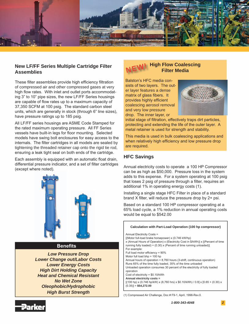
New LF/FF Series Multiple Cartridge Filter Assemblies These filter assemblies provide high efficiency filtration of compressed air and other compressed gases at very high flow rates. With inlet and outlet ports accommodat-ing 3” to 10” pipe sizes, the new LF/FF Series housings are capable of flow rates up to a maximum capacity of 37,350 SCFM at 100 psig. The standard carbon steel units, which are generally in stock (through 6” line sizes), have pressure ratings up to 185 psig. All LF/FF series housings are ASME Code Stamped for the rated maximum operating pressure. All FF Series vessels have built-in legs for floor mounting. Selected models have swing bolt enclosures for easy access to the internals. The filter cartridges in all models are sealed by tightening the threaded retainer cap onto the rigid tie rod, ensuring a leak tight seal on both ends of the cartridge. Each assembly is equipped with an automatic float drain, differential pressure indicator, and a set of filter cartridges (except where noted).
HFC Savings Annual electricity costs to operate a 100 HP Compressor can be as high as $50,000. Pressure loss in the system adds to this expense. For a system operating at 100 psig that loses 2 psig of pressure through a filter, requires an additional 1% in operating energy costs (1). Installing a single stage HFC Filter in place of a standard brand X filter, will reduce the pressure drop by 2+ psi.Based on a standard 100 HP compressor operating at a 65% load cycle, a 1% reduction in annual operating costs would be equal to $542.00
Calculation with Part-Load Operation (100 hp compressor)
Annual Electricity Costs = [(Motor full-load brake horsepower) x (0.746 kW/hp) x (Annual Hours of Operation) x (Electricity Cost in $/kWh)] x [(Percent of time running fully loaded) + (0.30) x (Percent of time running unloaded)]For example: Full load motor efficiency = 90%Motor full load bhp = 100 hpAnnual hours of operation = 8,760 hours (3-shift, continuous operation)Runs 65% of the time fully loaded, 35% of the time unloadedUnloaded operation consumes 30 percent of the electricity of fully loaded operationCost of electricity = $0.10/kWhAnnual electricity costs = [(100 hp) x (0.746 hp/kW) x (8,760 hrs) x $0.10/kWh) / 0.9] x [0.65 + (0.30) x (0.35)] = $54,272.00
High Flow Coalescing Filter Media
Balston’s HFC media con-sists of two layers. The out-er layer features a dense matrix of glass fibers. It provides highly efficient coalescing aerosol removal and very low pressure drop. The inner layer, or initial stage of filtration, effectively traps dirt particles, protecting and extending the life of the outer layer. A metal retainer is used for strength and stability.This media is used in bulk coalescing applications and when relatively high efficiency and low pressure drop are required.
NEW!
Low Pressure DropLower Change out/Labor Costs
Lower Energy CostsHigh Dirt Holding Capacity
Heat and Chemical ResistantNo Wet Zone
Oleophobic/HydrophobicHigh Burst Strength
Benefits
(1) Compressed Air Challenge, Doc # F9-1, April, 1998-Rev.0.
Bulletin ASME.indd 2 1/24/2007 10:21:47 AM

3 www.parker.com/balston
Max. Rated Flows (SCFM) at Various Operating Pressures(0.25 psi pressure drop)
Housing Selection Chart
2 20 40 80 100 125 150 185 Model Number PSIG PSIG PSIG PSIG PSIG PSIG PSIG PSIG
ALN3-0128-HFC 363 753 1187 2056 2490 3033 3575 4335 ALF3-0128-HFC 363 753 1187 2056 2490 3033 3575 4335 ALF4-0125-HFC 483 1004 1583 2741 3320 4044 4767 5780 ALF6-0136-HFC 725 1507 2375 4112 4980 6065 7151 8670 ALF6-0328-HFC 1088 2260 3562 6167 7470 9098 10726 13006 AFN3-0128-HFC 363 753 1187 2056 2490 3033 3575 4335 AFF3-0128-HFC 363 753 1187 2056 2490 3033 3575 4335 AFF4-0125-HFC 483 1004 1583 2741 3320 4044 4767 5780 AFF6-0136-HFC 725 1507 2375 4112 4980 6065 7151 8670 AFF6-0328-HFC 1088 2260 3562 6167 7470 9098 10726 13006 AFF8-0428-HFC 1450 3013 4750 8223 9960 12131 14302 17341 AFF10-0728-HFC 2538 5273 8312 14391 17430 21229 25028 30347 AFF12-1128-HFC 3988 8286 13062 22614 27390 33360 39330 47688 AFF16-1528-HFC 5438 11299 17812 30837 37350 45491 53632 65029
Rated Flows Grade HFC: Replacement Port Port # of SCFM @ 100 PSIG Model Number Element # Size Type Elements (m3hr@7bar)
LINE MOUNT VESSELS ALN3-0128-HFC 510-28- HFC 3 NPT 1 2490 (2490) ALF3-0128-HFC 510-28- HFC 3 FLANGE 1 2490 (4230) ALF4-0125-HFC 850-25- HFC 4 FLANGE 1 3320 (5640) ALF6-0136-HFC 850-28- HFC 6 FLANGE 1 4980 (8460) ALF6-0328-HFC 510-28- HFC 6 FLANGE 3 7470 (12690) FLOOR MOUNT VESSELS AFN3-0128-HFC 510-28- HFC 3 NPT 1 2490 (4230) AFF3-0128-HFC 510-28- HFC 3 FLANGE 1 2490 (4230) AFF4-0125-HFC 850-25- HFC 4 FLANGE 1 3320 (5640) AFF6-0136-HFC 850-36- HFC 6 FLANGE 1 4980 (8460) AFF6-0328-HFC 510-28- HFC 6 FLANGE 3 7470 (12690) AFF8-0428-HFC 510-28- HFC 8 FLANGE 4 9960 (16920) AFF10-0728-HFC 510-28- HFC 10 FLANGE 7 17430 (2961) AFF12-1128-HFC 510-28- HFC 12 FLANGE 11 27390 (4653) AFF16-1528-HFC 510-28- HFC 16 FLANGE 15 37350 (6345)
t
t
t
t
Bulletin ASME.indd 3 1/24/2007 10:22:00 AM

�-800-343-4048 4
Materials of Construction:
Body Carbon Steel
Paint Epoxy Enamel
Internals Epoxy powder painted carbon steel
Seals Inorganic flange gasket (single element vessels) Fluorocarbon o-ring (multi-element vessels)
Internal Coating Epoxy enamel
Specifications:
Max. Pressure 185 psig (12.5 bar)
Max. Temperature 450°F (232°C)
Meets
A.S.M.E. Code, Section VIII, Division 1
Note: Consult factory for special requirements.
Filtration & Separation Division 242 Neck Road, P.O. Box 8223 Haverhill, MA 01835-0723Tel: 1-800-343-4048, Fax: 1-978-556-7501www.parker.com/balston
Reprinted in USA January, 2007Copyright© Parker Hannifin Corporation, 2006, 2007
Bulletin ASME-A
Element Removal Sump Model A B C D E Clearance Capacity (2) Weight (3)
ALN3-0128-HFC 43.1 (109.5) 15.0 (38.1) 7.7 (19.5) 35.4 (89.9) --- 28 (71.1) 0.81 (3) 190 (86)
ALF3-0128-HFC 43.1 (109.5) 16.0 (40.6) 7.7 (19.5) 35.4 (89.9) --- 28 (71.1) 0.81 (3) 190 (86)
ALF4-0125-HFC 42.7 (108.5) 20.0 (50.8) 9.7 (24.6) 33.0 (83.8) --- 25 (63.5) 2.0 (7) 390 (173)
ALF6-0136-HFC 56.4 (143.3) 20.0 (50.8) 11.4 (29.0) 45.00 (114.3) --- 36 (91.4) 2.0 (7) 380 (173)
ALF6-0328-HFC 57.8 (146.8) 26.0 (66.0) 11.0 (27.9) 39.8 (101) --- 28 (71.1) 2.0 (7) 340 (155)
AFN3-0128-HFC 58.9 (149.6) 15.0 (38.1) 9.4 (23.8) 37.5 (95.2) 12.0 (30.4) 28 (71.1) 1.1 (4) 190 (86)
AFF3-0128-HFC 58.9 (149.6) 16.0 (40.6) 9.4 (23.8) 37.5 (95.2) 12.0 (30.4) 28 (71.1) 1.2 (4) 200 (91)
AFF4-0125-HFC 63.3 (160.7) 20.0 (50.8) 12.3 (31.2) 35.0 (88.9) 16.0 (40.6) 25 (63.5) 4.2 (16) 370 (168)
AFF6-0136-HFC 75.3 (191.2) 20.0 (50.8) 12.3 (31.2) 35.0 (88.9) 16.0 (40.6) 25 (63.5) 4.2 (16) 370 (168)
AFF6-0328-HFC 75.3 (191.2) 20.0 (50.8) 12.3 (31.2) 47.0 (119.3) 16.0 (40.6) 36 (91.4) 3.6 (14) 410 (186)
AFF8-0428-HFC 87.3 (221.7) 30.0 (76.2) 25.8 (65.5) 42.5 (108.0) 19.0 (48.3) 28 (71.1) 8.7 (33) 550 (250)
AFF10-0728-HFC 96.0 (243.8) 34.0 (86.3) 28.5 (72.4) 45.4 (115.5) 22.0 (55.8) 28 (71.1) 14.8 (56) 750 (341)
AFF12-1128-HFC 101.0 (256.5) 44.0 (111.7) 27.5 (69.8) 47.5 (120.6) 26.0 (66.0) 28 (71.1) 25.5 (97) 1300 (591)
AFF16-1528-HFC 112.0 (28.4) 52.0 (132.0) 32.0 (81.3) 50.0 (127.0) 30.0 (76.2) 28 (71.1) 56.2 (231) 1700 (773)
(1) Dimensions are in inches (cm). (2) Sump Capacity is in gallons (liters). (3) Weight is in pounds (kg).
Refer to thisdrawing for: FF6-0328FF8-0428
FF10-0728FF12-1128FF16-1528
Drawings, Dimensions & Specifications
Refer to thisdrawing for: LN3-0128LF3-0128LF4-0125LF6-0136
Refer to thisdrawing for: LF6-0328
Refer to thisdrawing for: FN3-0128FF3-0128FF4-0125FF6-0136
B
D
A
C
A D
B
C
1/2 NPT Vent
1/4 NPT Gauge Ports
1/2 NPT Drain
1/2 NPT Vent
AD
E
C
B
A D
E
C
B
1/2 NPT Vent
1/4 NPT Gauge
Port
1/2 NPT Vent
1/4 NPT Gauge
Port
1/4 NPT Gauge
Port
1/2 NPT Drain
1/2 NPT Drain
1/4 NPT Gauge Ports
1/2 NPT Drain1/2 NPT
Drain
1/4 NPT Gauge
Port
1/2 NPT Drain
Bulletin ASME.indd 4 1/24/2007 10:22:03 AM