bandwidth-efficient modulations—summary of … · standardization of modulation methods for high...
TRANSCRIPT
Report Concerning Space Data System Standards
GREEN BOOK
BANDWIDTH-EFFICIENTMODULATIONS—SUMMARY OF DEFINITION,
IMPLEMENTATION, AND PERFORMANCE
INFORMATIONAL REPORT
CCSDS 413.0-G-3
February 2018
Report Concerning Space Data System Standards
BANDWIDTH-EFFICIENT MODULATIONS— SUMMARY OF DEFINITION,
IMPLEMENTATION, AND PERFORMANCE
INFORMATIONAL REPORT
CCSDS 413.0-G-3
GREEN BOOK February 2018

CCSDS REPORT CONCERNING BANDWIDTH-EFFICIENT MODULATIONS
CCSDS 413.0-G-3 Page i February 2018
AUTHORITY
Issue: Informational Report, Issue 3
Date: February 2018
Location: Washington, DC, USA
This document has been approved for publication by the Management Council of the Consultative Committee for Space Data Systems (CCSDS) and reflects the consensus of technical panel experts from CCSDS Member Agencies. The procedure for review and authorization of CCSDS Reports is detailed in Organization and Processes for the Consultative Committee for Space Data Systems (CCSDS A02.1-Y-4).
This document is published and maintained by:
CCSDS Secretariat National Aeronautics and Space Administration Washington, DC, USA E-mail: [email protected]

CCSDS REPORT CONCERNING BANDWIDTH-EFFICIENT MODULATIONS
CCSDS 413.0-G-3 Page ii February 2018
FOREWORD
This Report contains technical material to supplement the CCSDS recommendations for the standardization of modulation methods for high symbol rate transmissions generated by CCSDS Member Agencies.
Through the process of normal evolution, it is expected that expansion, deletion, or modification of this document may occur. This Report is therefore subject to CCSDS document management and change control procedures, which are defined in Organization and Processes for the Consultative Committee for Space Data Systems (CCSDS A02.1-Y-4). Current versions of CCSDS documents are maintained at the CCSDS Web site:
http://www.ccsds.org/
Questions relating to the contents or status of this document should be sent to the CCSDS Secretariat at the e-mail address indicated on page i.
CCSDS REPORT CONCERNING BANDWIDTH-EFFICIENT MODULATIONS
CCSDS 413.0-G-3 Page iii February 2018
At time of publication, the active Member and Observer Agencies of the CCSDS were:
Member Agencies – Agenzia Spaziale Italiana (ASI)/Italy. – Canadian Space Agency (CSA)/Canada. – Centre National d’Etudes Spatiales (CNES)/France. – China National Space Administration (CNSA)/People’s Republic of China. – Deutsches Zentrum für Luft- und Raumfahrt (DLR)/Germany. – European Space Agency (ESA)/Europe. – Federal Space Agency (FSA)/Russian Federation. – Instituto Nacional de Pesquisas Espaciais (INPE)/Brazil. – Japan Aerospace Exploration Agency (JAXA)/Japan. – National Aeronautics and Space Administration (NASA)/USA. – UK Space Agency/United Kingdom.
Observer Agencies – Austrian Space Agency (ASA)/Austria. – Belgian Federal Science Policy Office (BFSPO)/Belgium. – Central Research Institute of Machine Building (TsNIIMash)/Russian Federation. – China Satellite Launch and Tracking Control General, Beijing Institute of Tracking and
Telecommunications Technology (CLTC/BITTT)/China. – Chinese Academy of Sciences (CAS)/China. – Chinese Academy of Space Technology (CAST)/China. – Commonwealth Scientific and Industrial Research Organization (CSIRO)/Australia. – Danish National Space Center (DNSC)/Denmark. – Departamento de Ciência e Tecnologia Aeroespacial (DCTA)/Brazil. – Electronics and Telecommunications Research Institute (ETRI)/Korea. – European Organization for the Exploitation of Meteorological Satellites (EUMETSAT)/Europe. – European Telecommunications Satellite Organization (EUTELSAT)/Europe. – Geo-Informatics and Space Technology Development Agency (GISTDA)/Thailand. – Hellenic National Space Committee (HNSC)/Greece. – Indian Space Research Organization (ISRO)/India. – Institute of Space Research (IKI)/Russian Federation. – Korea Aerospace Research Institute (KARI)/Korea. – Ministry of Communications (MOC)/Israel. – Mohammed Bin Rashid Space Centre (MBRSC)/United Arab Emirates. – National Institute of Information and Communications Technology (NICT)/Japan. – National Oceanic and Atmospheric Administration (NOAA)/USA. – National Space Agency of the Republic of Kazakhstan (NSARK)/Kazakhstan. – National Space Organization (NSPO)/Chinese Taipei. – Naval Center for Space Technology (NCST)/USA. – Research Institute for Particle & Nuclear Physics (KFKI)/Hungary. – Scientific and Technological Research Council of Turkey (TUBITAK)/Turkey. – South African National Space Agency (SANSA)/Republic of South Africa. – Space and Upper Atmosphere Research Commission (SUPARCO)/Pakistan. – Swedish Space Corporation (SSC)/Sweden. – Swiss Space Office (SSO)/Switzerland. – United States Geological Survey (USGS)/USA.
CCSDS REPORT CONCERNING BANDWIDTH-EFFICIENT MODULATIONS
CCSDS 413.0-G-3 Page iv February 2018
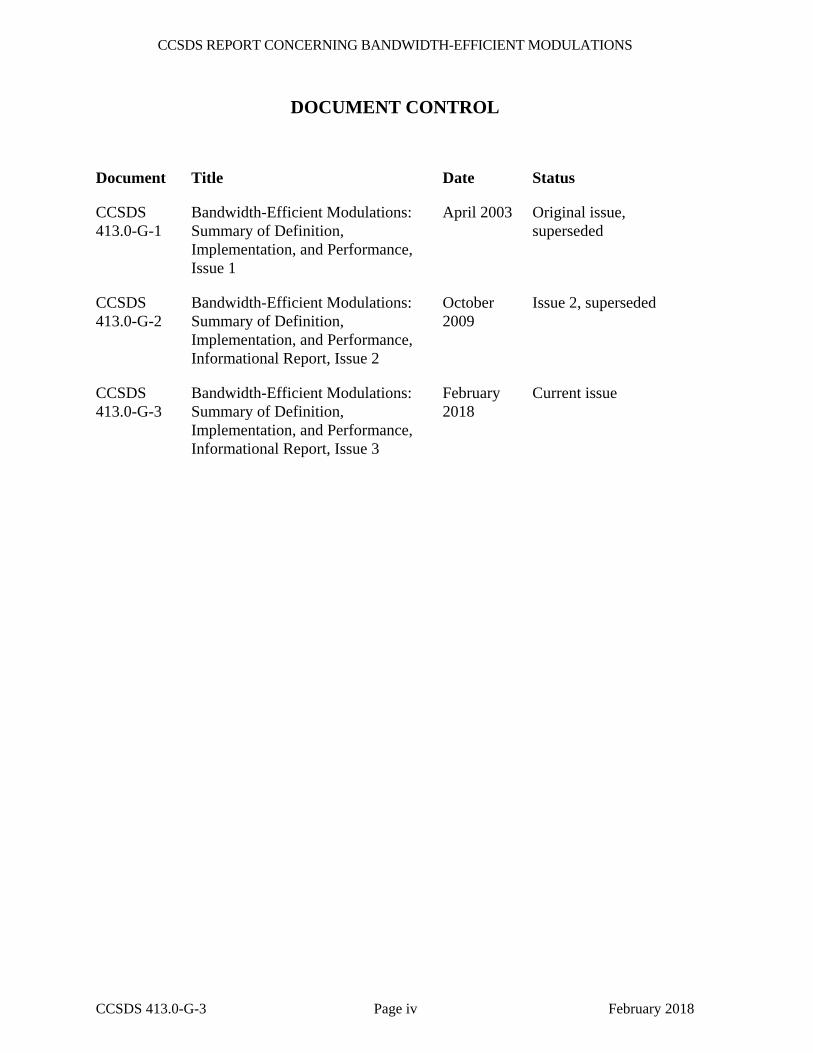
DOCUMENT CONTROL
Document Title Date Status
CCSDS 413.0-G-1
Bandwidth-Efficient Modulations: Summary of Definition, Implementation, and Performance, Issue 1
April 2003 Original issue, superseded
CCSDS 413.0-G-2
Bandwidth-Efficient Modulations: Summary of Definition, Implementation, and Performance, Informational Report, Issue 2
October 2009
Issue 2, superseded
CCSDS 413.0-G-3
Bandwidth-Efficient Modulations: Summary of Definition, Implementation, and Performance, Informational Report, Issue 3
February 2018
Current issue

CCSDS REPORT CONCERNING BANDWIDTH-EFFICIENT MODULATIONS
CCSDS 413.0-G-3 Page v February 2018
CONTENTS
Section Page
1 INTRODUCTION .......................................................................................................... 1-1 1.1 PURPOSE AND SCOPE ........................................................................................ 1-1 1.2 APPLICABILITY ................................................................................................... 1-2 1.3 REFERENCES ....................................................................................................... 1-2
2 SCOPE OF BANDWIDTH-EFFICIENT MODULATIONS .................................... 2-1
2.1 LIMITED SPECTRAL RESOURCES FOR SPACE TELEMETRY .................... 2-1 2.2 REGULATIONS: THE SFCG SPECTRAL MASK .............................................. 2-1 2.3 A SELECTION OF BANDWIDTH-EFFICIENT MODULATION
METHODS ............................................................................................................. 2-2 2.4 BIT AND SYMBOL RATE TERMINOLOGY ..................................................... 2-4
3 TECHNICAL DEFINITIONS ...................................................................................... 3-1
3.1 PRECODED GMSK ............................................................................................... 3-1 3.2 FILTERED OFFSET-QPSK ................................................................................. 3-12 3.3 4D 8PSK TRELLIS-CODED MODULATION ................................................... 3-23 3.4 SRRC-8PSK, SRRC-16APSK, SRRC-32APSK AND SRRC-64APSK
MODULATIONS ................................................................................................. 3-37 4 SUMMARY .................................................................................................................... 4-1 ANNEX A GLOSSARY ................................................................................................... A-1 ANNEX B SIMULATED MODULATION PERFORMANCE WITH SSPA
OPERATING IN SATURATION .................................................................B-1
Figure
2-1 Bit and Symbol Rate Terminology ............................................................................... 2-4 3-1 GMSK Precoder ............................................................................................................ 3-1 3-2 GMSK: Generated Using VCO .................................................................................... 3-3 3-3 GMSK Using a Quadrature Modulator ......................................................................... 3-3 3-4 Simulated GMSK Spectrum at Output of Saturated SSPA .......................................... 3-3 3-5 NRZ Signal Affected by Symbol Asymmetry (η=0.25) ............................................... 3-4 3-6 Bit Error Rate (BER) at the Output of the GMSK Receiver in the
Presence of Data Asymmetry; Case of BTs=0.5 ........................................................... 3-5 3-7 Bit Error Rate (BER) at the Output of the GMSK Receiver in the
Presence of Data Asymmetry; Case of BTs=0.25 ......................................................... 3-5
CCSDS REPORT CONCERNING BANDWIDTH-EFFICIENT MODULATIONS
CCSDS 413.0-G-3 Page vi February 2018
CONTENTS (continued)
Figure Page
3-8 Bit Error Rate (BER) at the Output of the GMSK Receiver in the Presence of Carrier Phase/Amplitude Imbalance ......................................................... 3-6
3-9 The FM-1 Implementation of the Precoded GMSK Transmitter ................................. 3-7 3-10 Pulses C0(t) and C1(t) with BTs=0.25 (left) and BTs=0.5 (right) ................................. 3-7 3-11 IQ-L1 Implementation of the Transmitter .................................................................... 3-8 3-12 Scattering Diagram for the IQ-L1 Implementation with 1 and 2
Amplitude Components; GMSK with BTs=0.5 ............................................................ 3-9 3-13 Scattering Diagram for the IQ-L1 Implementation with 1 and 2
Amplitude Components; GMSK with BTs=0.25 .......................................................... 3-9 3-14 Eye Pattern at the Output of the Receiver Filter for GMSK with BTs=0.5 ................ 3-10 3-15 Eye Pattern at the Output of the Receiver Filter for GMSK with BTs=0.25 .............. 3-10 3-16 Eye Pattern at the Output of the Wiener Equalizer for GSMK with BTs=0.25 .......... 3-11 3-17 Comparison of the GMSK BTs=0.5 Power Spectra Obtained with an
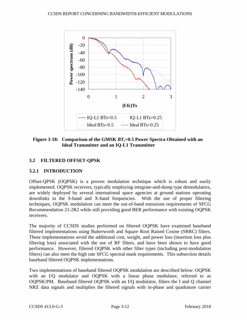
Ideal Transmitter and an FM-2 Transmitter ............................................................... 3-11 3-18 Comparison of the GMSK BTs=0.5 Power Spectra Obtained with an
Ideal Transmitter and an IQ-L1 Transmitter .............................................................. 3-12 3-19 Filtered OQPSK with Linear Phase Modulator (OQPSK/PM) .................................. 3-13 3-20 Baseband Filtered OQPSK/PM Implementation Phasor Diagrams ............................ 3-14 3-21 Baseband Filtered OQPSK with I/Q Modulator ......................................................... 3-15 3-22 Baseband Filtered OQPSK I/Q Implementation Phasor Diagrams ............................ 3-16 3-23 Butterworth Filter Magnitude and Phase Response.................................................... 3-17 3-24 PSD for I/Q and PM Implementations of Baseband Filtered OQPSK
with the Recommended Butterworth Filter ................................................................ 3-18 3-25 Magnitude and Phase Response of SRRC (α = 0.5) Filter ......................................... 3-19 3-26 PSD for I/Q and PM Implementations of Baseband Filtered OQPSK
with the Recommended SRRC Filter .......................................................................... 3-19 3-27 Nyquist Pulse-Shaped SRRC OQPSK Modulator Based on Theoretical Equation ... 3-21 3-28 Simulated Spectrum of Nyquist Pulse-Shaped SRRC (α=0.5) OQPSK
at Output of Saturated SSPA ...................................................................................... 3-21 3-29 Magnitude and Phase Response of 6th Order BTs = 0.5 Bessel Filter ........................ 3-22 3-30 PSD for I/Q and PM Implementations of Baseband Filtered OQPSK
with a 6th Order BTs = 0.5 Bessel Filter ..................................................................... 3-23 3-31 Structure of the 4D 8PSK-TCM Coder/Mapper ......................................................... 3-25 3-32 Differential Coder and Modulo-8 Adder Principle ..................................................... 3-26 3-33 Convolutional Coder Recommended for High Data Rates ......................................... 3-26 3-34 Constellation Mapper for 2 Bits/Channel-Symbol ..................................................... 3-27 3-35 Constellation Mapper for 2.25 Bits/Channel-Symbol ................................................ 3-28 3-36 Constellation Mapper for 2.5 Bits/Channel-Symbol .................................................. 3-29 3-37 Constellation Mapper for 2.75 Bits/Channel-Symbol ................................................ 3-30 3-38 Coder and Mapper Implementation for 2 Bits/Channel-Symbol Efficiency .............. 3-31 3-39 Coder and Mapper Implementation at 2.25 Bits/Channel-Symbol Efficiency ........... 3-31
CCSDS REPORT CONCERNING BANDWIDTH-EFFICIENT MODULATIONS
CCSDS 413.0-G-3 Page vii February 2018
CONTENTS (continued)
Figure Page
3-40 Coder and Mapper Implementation at 2.5 Bits/Channel-Symbol Efficiency ............. 3-32 3-41 Coder and Mapper Implementation at 2.75 Bits/Channel-Symbol Efficiency ........... 3-32 3-42 4D-8PSK-TCM Phase Noise Mask Recommendation ............................................... 3-33 3-43 Transmit Structure for Baseband Square Root Raised Cosine Shaping ..................... 3-34 3-44 SRRC (α = 0.35) Shaped 4D-8PSK-TCM Phasor Diagram ...................................... 3-35 3-45 RC (α = 0.35) Shaped 4D-8PSK-TCM Phase Eye Diagram at Output
of Matched Filter ........................................................................................................ 3-35 3-46 Transfer Function for 4 Poles/2 Zeros Elliptic Filter ................................................. 3-36 3-47 Transmit Structure for Post-Amplifier Shaping ......................................................... 3-36 B-1 AM/AM Characteristic of Reference SSPA .................................................................B-1 B-2 AM/PM Characteristic of Reference SSPA ..................................................................B-2 B-3 Principle of the 4D-8PSK-TCM Decoder Used in Simulations ...................................B-6 B-4 4D-8PSK-TCM BER vs. Eb/No in dB for 2, 2.25, 2.5, and
2.75 Bits/Channel Symbols ..........................................................................................B-7
Table
3-1 Bit Mapping for Differential Coder ............................................................................ 3-25 4-1 CCSDS Recommendations on Bandwidth-Efficient Modulations ............................... 4-2 B-1 Occupied Bandwidth of Category A Recommended Efficient Modulations
after Spectral Regrowth Due to Saturated SSPA ..........................................................B-3 B-2 Occupied Bandwidth of Category B Recommended Efficient Modulations
after Spectral Regrowth Due to Saturated SSPA ..........................................................B-3 B-3 Simulated Uncoded BER Performance of Recommended Category A
Efficient Modulations with Distortions Due to Saturated SSPA ..................................B-4 B-4 Simulated Uncoded BER Performance of Recommended Category B
Efficient Modulations with Distortions Due to Saturated SSPA ..................................B-4 B-5 Simulated BER Performance of Category A Efficient Modulations with
Concatenated Code in Non-Linear Channel .................................................................B-5 B-6 Simulated Uncoded BER Performance of Recommended Category B
Efficient Modulation with Concatenated Code in Non-Linear Channel ......................B-5 B-7 Narrowband Interference Susceptibility .......................................................................B-8 B-8 Wideband Interference Susceptibility ...........................................................................B-9 B-9 Co-Channel Interference ...............................................................................................B-9 B-10 Simulated Uncoded Loss of Category A Efficient Modulations Using
I&D Receiver ..............................................................................................................B-10 B-11 Simulated Uncoded Loss of Recommended Category B Efficient
Modulations with I&D Receiver ................................................................................B-11 B-12 Cross Support BER Performance of Recommended Modulation Formats
Using Other Receiver Types .......................................................................................B-11
CCSDS REPORT CONCERNING BANDWIDTH-EFFICIENT MODULATIONS
CCSDS 413.0-G-3 Page 1-1 February 2018
1 INTRODUCTION
1.1 PURPOSE AND SCOPE
Since their inception, the various international space agencies have operated an ever-increasing number of science missions in the Earth Exploration Satellite Service (EESS) and Space Research Service (SRS) bands. The data transport requirements of these missions have also continued to escalate, with the result that the finite spectrum resources are now becoming increasingly strained.
To mitigate this situation and reduce the possibility of adjacent channel interference, spectrum advisory and regulatory agencies such as the Space Frequency Coordination Group (SFCG) and the International Telecommunication Union (ITU) have recently enacted out-of-band emission mask recommendations. These masks are designed to severely restrict the power in that portion of transmitted signal falling outside some necessary bandwidth.
CCSDS has responded by developing a series of recommendations for standard bandwidth-efficient modulation techniques applicable to high rate missions in selected SRS and EESS bands. These modulations were selected based on their spectral containment characteristics, with the characteristics of the SFCG Recommendation 21-2R4 mask serving as a minimum requirement. Bit Error Rate (BER) performance, compatibility with existing infrastructure, and suitability for cross-support were also significant factors in selecting modulations for these recommendations.
This Green Book provides the background information for CCSDS recommendations 401(2.4.17A), 401(2.4.17B), 401(2.4.18), 401(2.4.20B), 401(2.4.21A), and 401(2.4.23) addressing the use of spacecraft telemetry bandwidth-efficient modulations which were approved by the CCSDS Management Council in June 2017. This document provides a technical specification for the modulation techniques approved in the above-mentioned recommendations, together with a description of their main performance characteristics for the applications covered by the recommendations. All figures are simulations unless noted otherwise.
This document includes two annexes. Annex A is a glossary of acronyms used in the document. Annex B provides simulated performance data of the efficient modulations when amplified by a Solid State Power Amplifier (SSPA) operating with 0 dB output backoff referenced to maximum output power. This data includes occupied bandwidth, BER, and interference susceptibility of the bandwidth-efficient modulations. The data provided in annex B is indicative of system performance expected using the reference model. Performance of other systems will be highly dependent upon their transmitter and receiver characteristics. The performance data in annex B was extracted from study reports available in reference [1].
CCSDS REPORT CONCERNING BANDWIDTH-EFFICIENT MODULATIONS
CCSDS 413.0-G-3 Page 1-2 February 2018
1.2 APPLICABILITY
The modulation techniques described in this document are applicable to high symbol rate (> 2 Ms/s for 2 and 8 GHz space research, > 10 Ms/s for 26 GHz and > 20 Ms/s for 32 GHz space research) telemetry transmissions for missions in the SRS and EESS. Six classes of modulation techniques are identified:
– Those dedicated to space research, Category A missions, specified in recommendation 401(2.4.17A) B-1. They are applicable to frequency bands 2200-2290 MHz and 8450-8500 MHz.
– Those dedicated to space research, Category B missions, specified in recommendation 401(2.4.17B) B-1. They are applicable to frequency bands 2290-2300 MHz and 8400-8450 MHz.
– Those dedicated to Earth exploration satellite missions, specified in recommendation 401(2.4.18) B-1. They are applicable to the frequency band 8025-8400 MHz.
– Those dedicated to space research, Category B missions, specified in recommendation 401(2.4.20B) B-1. They are applicable to the frequency band 31800-32300 MHz.
– Those dedicated to space research, Category A missions, specified in recommendation 401(2.4.21A) B-1. They are applicable to frequency band 25500-27000 MHz.
– Those dedicated to Earth exploration satellite missions, specified in recommendation 401(2.4.23) B-1. They are applicable to the frequency band 25500-27000 MHz.
It should be noted that, sensu stricto, the above recommendations are applicable only to the mentioned frequency bands. However, the user should take note that extension to other SRS and/or EESS frequency bands could be envisaged in the future.
In no event will CCSDS or its members be liable for any incidental, consequential, or indirect damages, including any lost profits, lost savings, or loss of data, or for any claim by another party related to errors or omissions in this report.
1.3 REFERENCES
The following documents are referenced in this Report. At the time of publication, the editions indicated were valid. All documents are subject to revision, and users of this Report are encouraged to investigate the possibility of applying the most recent editions of the documents indicated below. The CCSDS Secretariat maintains a register of currently valid CCSDS documents.
[1] Proceedings of the CCSDS RF and Modulation Subpanel 1E on Bandwidth-Efficient Modulations. Issue 2. CCSDS Record (Yellow Book), CCSDS B20.0-Y-2. Washington, D.C.: CCSDS, June 2001.
CCSDS REPORT CONCERNING BANDWIDTH-EFFICIENT MODULATIONS
CCSDS 413.0-G-3 Page 1-3 February 2018
[2] Radio Frequency and Modulation Systems—Part 1: Earth Stations and Spacecraft. Issue 28. Recommendation for Space Data System Standards (Blue Book), CCSDS 401.0-B-28. Washington, D.C.: CCSDS, February 2018.
[3] Organization and Processes for the Consultative Committee for Space Data Systems. Issue 4. CCSDS Record (Yellow Book), CCSDS A02.1-Y-4. Washington, D.C.: CCSDS, April 2014.
[4] K. Murota and K. Hirade. “GMSK Modulation for Digital Mobile Radio Telephony.” IEEE Transactions on Communications 29, no. 7 (1981): 1044–1050.
[5] “NASA GSFC Efficient Spectrum Utilization Analysis.” In Proceedings of the CCSDS RF and Modulation Subpanel 1E on Bandwidth-Efficient Modulations, 1-257–1-400. Issue 2. CCSDS B20.0-Y-2. Washington, D.C.: CCSDS, June 2001.
[6] J. Proakis and D. Manolakis. Introduction to Digital Signal Processing. New York: Macmillan USA, 1988.
[7] G. Ungerboeck. “Channel Coding with Multilevel/Phase Signals.” IEEE Transactions on Information Theory 28, no. 1 (1982): 55–67.
[8] S. S. Pietrobon, et al. “Trellis-Coded Multidimensional Phase Modulation.” IEEE Transactions on Information Theory 36, no. 1 (1990): 63–89.
[9] M. Austin and Ming Chang. “Quadrature Overlapped Raised-Cosine Modulation.” IEEE Transactions on Communications 29, no. 3 (1981): 237–249.
[10] S.S. Shah, S. Yaqub, and F. Suleman. “Self-Correcting Codes Conquer Noise, Part One: Viterbi Codecs.” EDN (February 15, 2001): 131–140.
[11] W. Martin, et al. “CCSDS-SFCG Efficient Modulation Methods Study at NASA/JPL, Phase 4: Interference Susceptibility.” In Proceedings of the CCSDS RF and Modulation Subpanel 1E on Bandwidth-Efficient Modulations, 1-171–1-212. Issue 2. CCSDS B20.0-Y-2. Washington, D.C.: CCSDS, June 2001.
[12] G. Povero, E. Vassallo, and M. Visintin. “Interference Susceptibility of Selected Bandwidth-Efficient Modulation Schemes.” In Proceedings of the CCSDS RF and Modulation Subpanel 1E on Bandwidth-Efficient Modulations, 1-473–1-492. Issue 2. CCSDS B20.0-Y-2. Washington, D.C.: CCSDS, June 2001.
[13] SCCC—Summary of Definition and Performance. Report Concerning Space Data System Standards (Green Book), CCSDS 130.11-G. Forthcoming.
[14] CCSDS Protocols over DVB-S2—Summary of Definition, Implementation, and Performance. Issue 1. Report Concerning Space Data System Standards (Green Book), CCSDS 130.12-G-1. Washington, D.C.: CCSDS, November 2016.
CCSDS REPORT CONCERNING BANDWIDTH-EFFICIENT MODULATIONS
CCSDS 413.0-G-3 Page 2-1 February 2018
2 SCOPE OF BANDWIDTH-EFFICIENT MODULATIONS
2.1 LIMITED SPECTRAL RESOURCES FOR SPACE TELEMETRY
The Category A SRS frequency band 2200-2290 MHz is currently heavily used by space research and space operations missions for their telemetry transmissions, and the density of users of the band keeps increasing over the years. In addition, while until recently all these users were rather modest in telemetry symbol rate transmission, more and more new missions are appearing with telemetry symbol rates well above 1 Ms/s. In order to avoid a rapid saturation of the band with unsolvable interference conflicts, the CCSDS has issued a recommendation 401(2.4.17A) for a limited set of common bandwidth-efficient modulation schemes to be used for high symbol rate transmissions, thus ensuring not only an optimum use of the band but also inter-agency cross-support capability. The recommendation is also applicable to the 8450-8500 MHz band for which a number of missions with high rate telemetry have already been earmarked.
Recommendation 401(2.4.21A) addresses the Category A SRS band 25500-27000 MHz.
Recommendation 401(2.4.17B) addresses the Category B SRS bands 2290-2300 MHz and 8400-8450 MHz, while recommendation 401(2.4.20B) addresses the 31.8-32.3 GHz Category B SRS band. These recommended modulations have been selected for their low loss and their bandwidth compactness.
Recommendations 401(2.4.18) and 401(2.4.23), respectively, address the EESS payload telemetry bands 8025-8400 MHz and 25.5-27 GHz. The band available at 8 GHz is only 375 MHz while some EESS missions are under preparation plan to transmit hundreds of Megabits per second of payload data leading to channel symbol rates possibly up to 1 Gs/s. The problem is two-fold: the physical limitation of the band in terms of transmission rate capacity and the increased risk of interference. CCSDS policy as expressed in recommendation 401(2.4.18) is to promote the use of a very compact modulation scheme for use in the 8 GHz band and to encourage the very high rate users to migrate to the 26 GHz band, for which the modulation scheme is defined in Recommendation 401(2.4.23).
2.2 REGULATIONS: THE SFCG SPECTRAL MASK
The SFCG was established to provide a less formal and more flexible environment, compared to the official organs of the ITU, for the solution of frequency management problems encountered by member space agencies. Recognizing that the SRS and EESS frequency bands were increasingly congested and concerned with the effective use of those bands, the SFCG approved Recommendation 17-2R1 in 1999 which established spectral emission limits for space-to-Earth links in the space science services. Separate spectral emissions masks were established for missions with telemetry data rates less than 2 Ms/s and for those with data rates greater than 2 Ms/s.
In September of 2003, the 17-2R1 mask was modified and renumbered 21-2R2 for Category A bands 2200-2290 MHz, 8025-8400 MHz, and 8450-8500 MHz. In June 2016, the
CCSDS REPORT CONCERNING BANDWIDTH-EFFICIENT MODULATIONS
CCSDS 413.0-G-3 Page 2-2 February 2018
recommendation became 21-2R4 with the addition of the 25500-27000 MHz band; the applicability of the mask in this band is for channel symbol rates starting at 10 Ms/s and projects designed for launch after 2020.
SFCG Recommendation 23-1 was also approved in September of 2003, providing guidance on the maximum allowable bandwidth as a function of data rates for space-to-Earth links in the Category B bands 2290-2300 MHz and 8400-8450 MHz. Its first revision, 23-1R1, was approved in June 2014.
The SFCG Recommendations currently in force can be found at the SFCG Web site https://www.sfcgonline.org/Resources/recommendations.
2.3 A SELECTION OF BANDWIDTH-EFFICIENT MODULATION METHODS
The selection of modulations schemes is the result of compromises on a number of criteria:
– bandwidth efficiency;
– link performances (in terms of BER);
– implementation complexity and cost: onboard transmitter, ground receiver;
– robustness: susceptibility to interferers;
– programmatic aspects: cross-compatibility.
2.3.1 MODULATION METHODS FOR SRS, CATEGORY A
Because of the wide range of applications, ranging from the low-Earth orbiters to the science spacecraft at the edge of the Category A region (2×10⁶ km), a number of different modulation schemes were retained in recommendation 401(2.4.17A) B-1 and recommendation 401(2.4.21A) B-1:
– GMSK1 (BTs=0.25) with precoding;
– Filtered OQPSK1 with various options:
• Baseband SRRC1, α=0.5;
• Baseband Butterworth 6 poles, BTs=0.5;
• Other types of bandpass filters provided that the equivalent baseband BTs is not greater than 0.5 and they ensure compliance with SFCG Recommendation 21-2R4 (or latest version) and interoperability with cross-supporting networks.
1These terms are defined in sections 3 and 4.
CCSDS REPORT CONCERNING BANDWIDTH-EFFICIENT MODULATIONS
CCSDS 413.0-G-3 Page 2-3 February 2018
2.3.2 MODULATION METHODS FOR SRS, CATEGORY B
For SRS Category B missions, only one modulation was retained in recommendation 401(2.4.17B) B-1 and recommendation 401(2.4.20B) B-1:
– GMSK2 (BTs=0.5) with precoding.
2.3.3 MODULATION METHODS FOR EESS AT 8 AND 26 GHZ
Recommendation 401(2.4.18) B-1 contains three sets of modulation options recommended for EESS missions at 8 GHz:
– 4D 8PSK TCM;2
– SRRC-QPSK, SRRC-OQPSK, SRRC-8PSK, SRRC-16APSK, SRRC-32APSK and SRRC-64APSK;3
– Filtered OQPSK2 with various options:
• Baseband SRRC2, α=0.5;
• Baseband Butterworth 6 poles, BTs=0.5;
• Other types of bandpass filters provided that the equivalent baseband BTs is not greater than 0.5 and they ensure compliance with SFCG Recommendation 21-2R4 (or latest version) and interoperability with cross-supporting networks.
4D 8PSK TCM and Filtered OQPSK are classical modulation schemes for this application, used by legacy missions as well as missions having no need for multi-mode operations or ACM or VCM. In case VCM or ACM is a mission requirement, then the family SRRC-QPSK, SRRC-OQPSK, SRRC-8PSK, SRRC-16APSK, SRRC-32APSK, and SRRC-64APSK is the natural selection, noting that it is not necessary to implement all the modes from QPSK to 64APSK to be CCSDS compliant.
Recommendation 401(2.4.23) B-1 contains one set of modulation options recommended for EESS missions at 26 GHz:
– SRRC-QPSK, SRRC-OQPSK, SRRC-8PSK, SRRC-16APSK, SRRC-32APSK, and SRRC-64APSK.3
Given that the use of the 26 GHz band is just starting, there is no need to cater to legacy missions, as is the case of the 8 GHz band. As for the 8 GHz case, there is no need to implement all the modes in the family to be CCSDS compliant.
2 These terms are defined in sections 3 and 4. 3 16/32/64APSK modulations are defined in reference [13], and 16/32APSK in reference [14].
CCSDS REPORT CONCERNING BANDWIDTH-EFFICIENT MODULATIONS
CCSDS 413.0-G-3 Page 2-4 February 2018
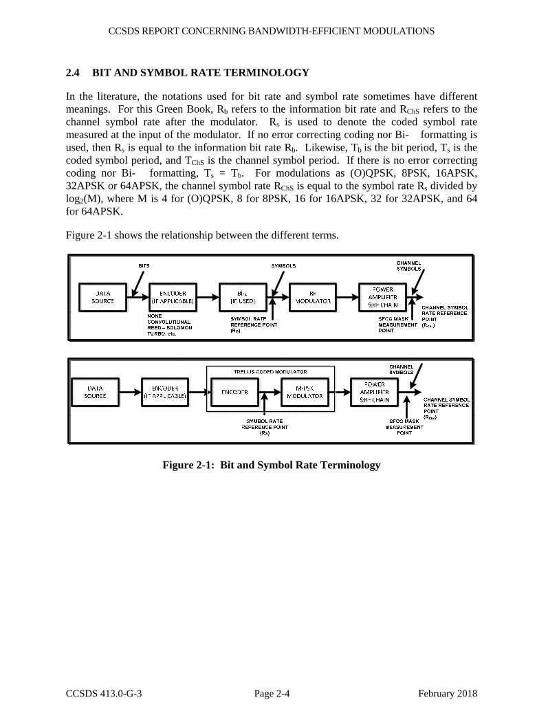
2.4 BIT AND SYMBOL RATE TERMINOLOGY
In the literature, the notations used for bit rate and symbol rate sometimes have different meanings. For this Green Book, Rb refers to the information bit rate and RChS refers to the channel symbol rate after the modulator. Rs is used to denote the coded symbol rate measured at the input of the modulator. If no error correcting coding nor Bi-� formatting is used, then Rs is equal to the information bit rate Rb. Likewise, Tb is the bit period, Ts is the coded symbol period, and TChS is the channel symbol period. If there is no error correcting coding nor Bi-� formatting, Ts = Tb. For modulations as (O)QPSK, 8PSK, 16APSK, 32APSK or 64APSK, the channel symbol rate RChS is equal to the symbol rate Rs divided by log2(M), where M is 4 for (O)QPSK, 8 for 8PSK, 16 for 16APSK, 32 for 32APSK, and 64 for 64APSK.
Figure 2-1 shows the relationship between the different terms.
Figure 2-1: Bit and Symbol Rate Terminology
CCSDS REPORT CONCERNING BANDWIDTH-EFFICIENT MODULATIONS
CCSDS 413.0-G-3 Page 3-1 February 2018
3 TECHNICAL DEFINITIONS
3.1 PRECODED GMSK
3.1.1 INTRODUCTION
Gaussian Minimum Shift Keying (GMSK) is a constant envelope, continuous phase modulation first introduced in 1981 by Murota and Hirade (reference [4]). It is derived from Minimum Shift Keying (MSK) with the addition of a baseband Gaussian filter that further reduces sidelobe levels and spectral bandwidth. The product of the Gaussian filter bandwidth and the coded symbol period at the input to the modulator, referred to as the BTs factor, is used to differentiate between GMSK modulations of varying bandwidth efficiencies. If there is no coding, BTs refers to the filter bandwidth times the bit period.4 In general, a smaller BTs factor results in less spectral bandwidth occupancy but greater intersymbol interference which can be compensated for using equalization or trellis demodulation. GMSK has a constant envelope which reduces spectral regrowth and signal distortion due to amplifier nonlinearity.
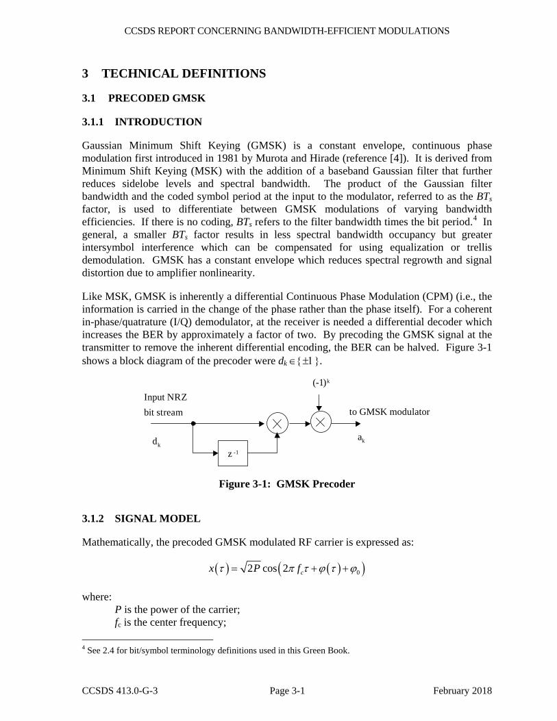
Like MSK, GMSK is inherently a differential Continuous Phase Modulation (CPM) (i.e., the information is carried in the change of the phase rather than the phase itself). For a coherent in-phase/quatrature (I/Q) demodulator, at the receiver is needed a differential decoder which increases the BER by approximately a factor of two. By precoding the GMSK signal at the transmitter to remove the inherent differential encoding, the BER can be halved. Figure 3-1 shows a block diagram of the precoder were dk ∈{±1}.
Input NRZbit stream
ak
z -1
dk
(-1)k
to GMSK modulator
Figure 3-1: GMSK Precoder
3.1.2 SIGNAL MODEL
Mathematically, the precoded GMSK modulated RF carrier is expressed as:
( ) ( )( )02 cos 2 cx P fτ π τ ϕ τ ϕ= + +
where: P is the power of the carrier; fc is the center frequency; 4 See 2.4 for bit/symbol terminology definitions used in this Green Book.
CCSDS REPORT CONCERNING BANDWIDTH-EFFICIENT MODULATIONS
CCSDS 413.0-G-3 Page 3-2 February 2018
φ(τ) is the phase of the modulated carrier; φ0 is a constant phase offset;
and
∑ ∫−
∞−
=k
kTt
k
s
dgat ))(2
()( ττπϕ
where ak = (−1)k dk dk−1 are the pre-coder output symbols and dk ∈{±1} is the k-th coded symbol to be transmitted.
The instantaneous frequency pulse g(τ) can be obtained through a linear filter with impulse response defined by:
g(τ) = h(τ) * rect (τ /Ts)
where * denotes convolution and rect(x) is the function:
rect (τ /Ts) = 1 / Ts for |τ | < Ts/2 rect (τ /Ts) = 0 otherwise
and h(t) is the Gaussian filter impulse response:
22
2
2
21)( sT
t
s
eT
th σ
πσ
−
=
where
sBTπσ
2)2ln(
=
and ln ( • ) is the natural logarithm (base = e) B = one-sided 3-dB bandwidth of the filter with impulse response h(t) Ts = the duration of a coded symbol at the input to the modulator
3.1.3 GMSK MODULATOR
3.1.3.1 General
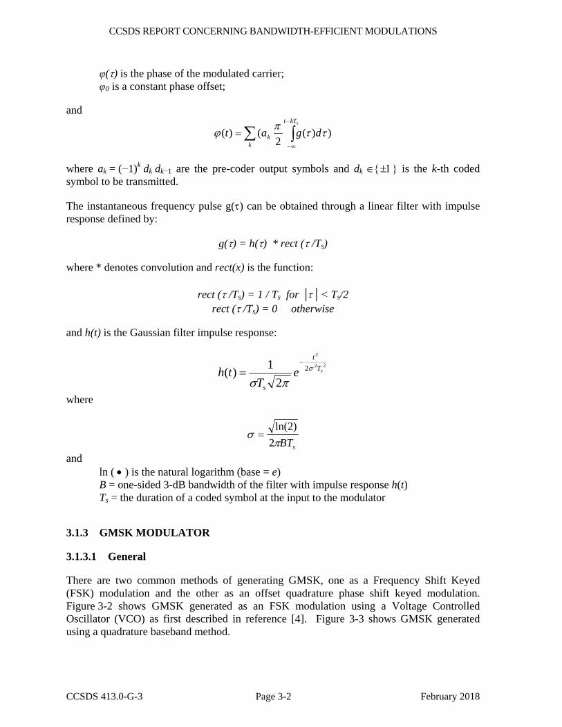
There are two common methods of generating GMSK, one as a Frequency Shift Keyed (FSK) modulation and the other as an offset quadrature phase shift keyed modulation. Figure 3-2 shows GMSK generated as an FSK modulation using a Voltage Controlled Oscillator (VCO) as first described in reference [4]. Figure 3-3 shows GMSK generated using a quadrature baseband method.
CCSDS REPORT CONCERNING BANDWIDTH-EFFICIENT MODULATIONS
CCSDS 413.0-G-3 Page 3-3 February 2018
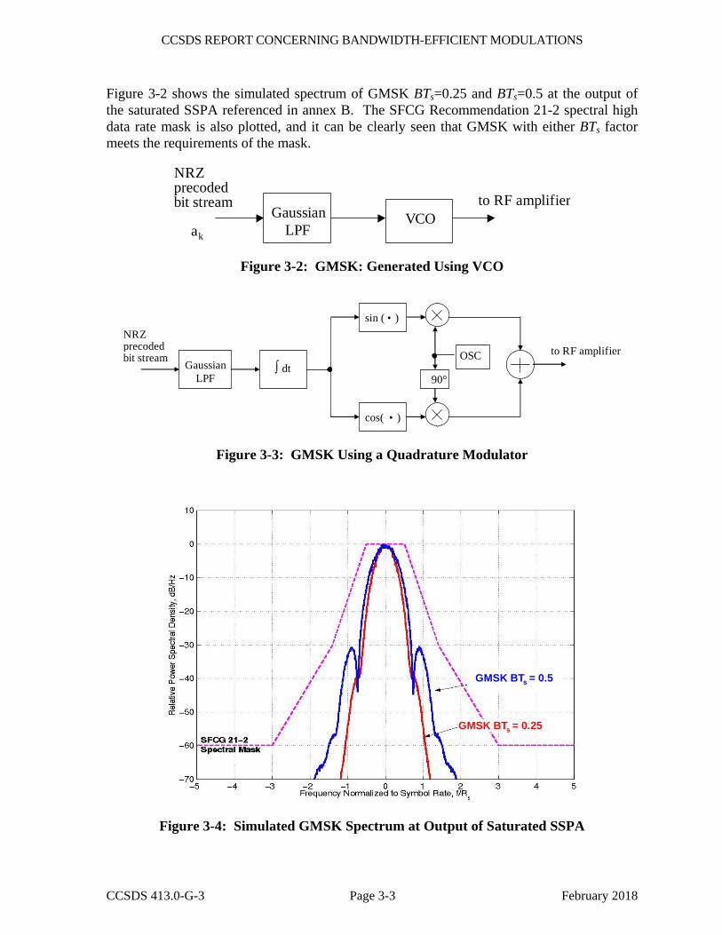
Figure 3-2 shows the simulated spectrum of GMSK BTs=0.25 and BTs=0.5 at the output of the saturated SSPA referenced in annex B. The SFCG Recommendation 21-2 spectral high data rate mask is also plotted, and it can be clearly seen that GMSK with either BTs factor meets the requirements of the mask.
NRZprecodedbit stream
ak
GaussianLPF
VCOto RF amplifier
Figure 3-2: GMSK: Generated Using VCO
NRZprecodedbit stream
GaussianLPF
to RF amplifier∫ dt
sin ( • )
cos( • )
90°
OSC
Figure 3-3: GMSK Using a Quadrature Modulator
GMSK BTs = 0.25
GMSK BTs = 0.5
GMSK BTs = 0.25
GMSK BTs = 0.5
Figure 3-4: Simulated GMSK Spectrum at Output of Saturated SSPA
CCSDS REPORT CONCERNING BANDWIDTH-EFFICIENT MODULATIONS
CCSDS 413.0-G-3 Page 3-4 February 2018
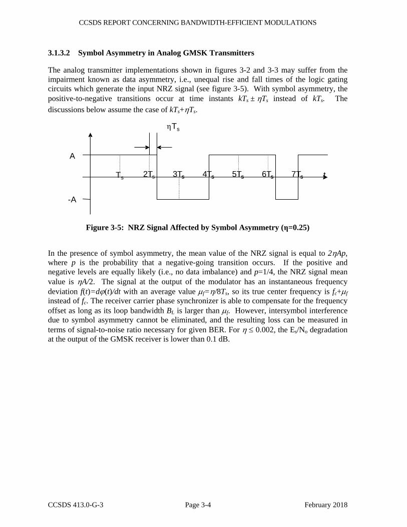
3.1.3.2 Symbol Asymmetry in Analog GMSK Transmitters
The analog transmitter implementations shown in figures 3-2 and 3-3 may suffer from the impairment known as data asymmetry, i.e., unequal rise and fall times of the logic gating circuits which generate the input NRZ signal (see figure 3-5). With symbol asymmetry, the positive-to-negative transitions occur at time instants kTs ± ηTs instead of kTs. The discussions below assume the case of kTs+ηTs.
T s s s s s
Ts
s 2Ts 3Ts 4Ts 5Ts s 7Ts t
A
-A
6T
η
Figure 3-5: NRZ Signal Affected by Symbol Asymmetry (η=0.25)
In the presence of symbol asymmetry, the mean value of the NRZ signal is equal to 2ηAp, where p is the probability that a negative-going transition occurs. If the positive and negative levels are equally likely (i.e., no data imbalance) and p=1/4, the NRZ signal mean value is ηA/2. The signal at the output of the modulator has an instantaneous frequency deviation f(t)=dϕ(t)/dt with an average value μf=η/8Ts, so its true center frequency is fc+μf instead of fc. The receiver carrier phase synchronizer is able to compensate for the frequency offset as long as its loop bandwidth BL is larger than μf. However, intersymbol interference due to symbol asymmetry cannot be eliminated, and the resulting loss can be measured in terms of signal-to-noise ratio necessary for given BER. For η ≤ 0.002, the Es/No degradation at the output of the GMSK receiver is lower than 0.1 dB.
CCSDS REPORT CONCERNING BANDWIDTH-EFFICIENT MODULATIONS
CCSDS 413.0-G-3 Page 3-5 February 2018
0.090
0.100
0.110
0.120
0.130
-1.6 -1.5 -1.4 -1.3 -1.2 -1.1 -1 -0.9 -0.8 -0.7 -0.6
Es/No (dB)
BE
R
BTs=0.5 ideal BTs=0.5 η=0.001 BTs=0.5 η=0.002
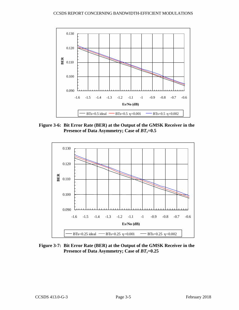
Figure 3-6: Bit Error Rate (BER) at the Output of the GMSK Receiver in the Presence of Data Asymmetry; Case of BTs=0.5
0.090
0.100
0.110
0.120
0.130
-1.6 -1.5 -1.4 -1.3 -1.2 -1.1 -1 -0.9 -0.8 -0.7 -0.6
Es/No (dB)
BE
R
BTs=0.25 ideal BTs=0.25 η=0.001 BTs=0.25 η=0.002
Figure 3-7: Bit Error Rate (BER) at the Output of the GMSK Receiver in the Presence of Data Asymmetry; Case of BTs=0.25

CCSDS REPORT CONCERNING BANDWIDTH-EFFICIENT MODULATIONS
CCSDS 413.0-G-3 Page 3-6 February 2018
3.1.3.3 Carrier Phase/Amplitude Imbalance in Quadrature GMSK Transmitters
In the quadrature GMSK modulator, two orthogonal sinusoidal signals are generated from one oscillator, using a π/2 phase shifter. The presence of carrier phase/amplitude imbalance due to implementation gives rise to spectral lines in the power spectrum of the transmitted signal and BER degradation at the receiver output. Simulations showed that the coherent receiver finds its stable phase reference at θ /2 and that the loss due to increased intersymbol interference is negligible as long as θ is less than 5° and the amplitude imbalance is lower than 0.5 dB (see figure 3-8).
BTsBTs
BTsBTs
Figure 3-8: Bit Error Rate (BER) at the Output of the GMSK Receiver in the Presence of Carrier Phase/Amplitude Imbalance
3.1.3.4 Parameters to be Used in Digital GMSK Transmitters
Full digital transmitters may be developed, based on the schemes of figures 3-2 and 3-3. The NRZ signal is sampled using Nb samples per coded symbol at the input to the modulator, and an FIR filter with impulse response h[n] is used instead of the analog Gaussian filter. This type of transmitter is denoted here as FM-2 if the VCO is present (figure 3-2) and IQ-2 if the IQ transmitter is present (figure 3-3). The value of Nb, the number of taps NT of the FIR filter, and the number of quantization bits Nq to be used in the FIR filter must be found so that the introduced approximations in the transmitted signal are negligible. Another possibility, which shall be called FM-1, is shown in figure 3-9. In this case, the NRZ input signal is sampled using one sample per bit. An oversampler introduces Nb-1 zeros between the two input samples and generates a train of discrete deltas which feed an FIR filter with impulse response g[n]. In figure 3-9 the digital-to-analog conversion is placed right after the

CCSDS REPORT CONCERNING BANDWIDTH-EFFICIENT MODULATIONS
CCSDS 413.0-G-3 Page 3-7 February 2018
FIR filter because an analog VCO is used, but a numerically controlled oscillator can be used instead. Moreover, a quadrature modulator may be used instead of the VCO, as in figure 3-3.
bn an
Nb
g[n]z[n]x(t) z(t)
nTb
bn an
z[n]D/AVCO
x(t) z(t)
bn
BitSource
Bit toLevel an
Z-1
(-1) n+1
bn an
Nb
g[n]z[n]x(t) z(t)
nTb
bn an
z[n]D/AVCO
x(t) z(t)
bn
BitSource
Bit toLevel an
Z-1
(-1) n+1
Figure 3-9: The FM-1 Implementation of the Precoded GMSK Transmitter
Another quadrature modulator (IQ-L1) can be designed, based on the Laurent decomposition of the GMSK signal complex envelope (see figure 3-11):
)]2()2([
)]2()2([)(~
122122012
11221202
snnnssn
nc
ssnnnsn
nc
nTtCbbbTnTtCbjA
TnTtCbbbnTtCbAtx
−−−−+
−−−−≈
−−
∞
−∞=+
−+
∞
−∞=
∑
∑
where C0(t) and C1(t) are shown in figure 3-10 for BTs=0.5 and BTs=0.25.
t/T s t/T s
Figure 3-10: Pulses C0(t) and C1(t) with BTs=0.25 (left) and BTs=0.5 (right)

CCSDS REPORT CONCERNING BANDWIDTH-EFFICIENT MODULATIONS
CCSDS 413.0-G-3 Page 3-8 February 2018
bitsource
bit tolevel
bn
nTb 2Nb
S/P
2Nb
z-1
z-1
MULTIPLY
S/P
2Nb
2Nb
gn
be[n]
bo[n]
ge[n]
go[n]
bo[n]C0[n] D/A
-Acsin(2πfct)
be[n]C0[n] D/A
Accos(2πfct)
ge[n]C1[n] D/A
-Accos(2πfct)
go[n]C1[n] D/A
Acsin(2πfct)
x(t)
Figure 3-11: IQ-L1 Implementation of the Transmitter
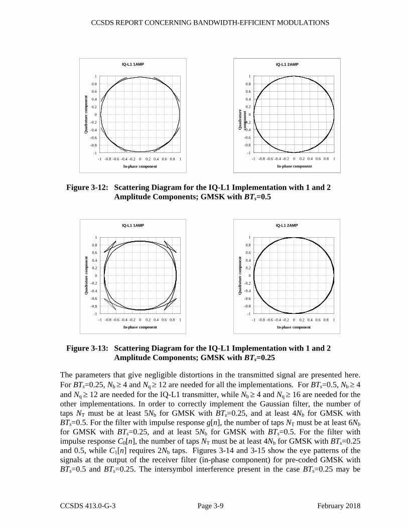
The complex envelopes of the signals generated with transmitter of figure 3-11 using only one amplitude (AMP) component (only C0(t)) or both components are shown in figures 3-12 and 3-13 for BTs=0.5 and BTs=0.25, respectively. The use of both components is needed for GMSK with BTs=0.25, while one component is sufficient for the generation of the GMSK signal with BTs=0.5.
CCSDS REPORT CONCERNING BANDWIDTH-EFFICIENT MODULATIONS
CCSDS 413.0-G-3 Page 3-9 February 2018
IQ-L1 1AMP
-1
-0.8
-0.6
-0.4
-0.2
0
0.2
0.4
0.6
0.8
1
-1 -0.8 -0.6 -0.4 -0.2 0 0.2 0.4 0.6 0.8 1
In-phase component
Qua
drat
ure
com
pone
nt
IQ-L1 2AMP
-1
-0.8
-0.6
-0.4
-0.2
0
0.2
0.4
0.6
0.8
1
-1 -0.8 -0.6 -0.4 -0.2 0 0.2 0.4 0.6 0.8 1
In-phase component
Qua
drat
ure
com
pone
nt
Figure 3-12: Scattering Diagram for the IQ-L1 Implementation with 1 and 2 Amplitude Components; GMSK with BTs=0.5
IQ-L1 1AMP
-1
-0.8
-0.6
-0.4
-0.2
0
0.2
0.4
0.6
0.8
1
-1 -0.8 -0.6 -0.4 -0.2 0 0.2 0.4 0.6 0.8 1
In-phase component
Qua
drat
ure
com
pone
nt
IQ-L1 2AMP
-1
-0.8
-0.6
-0.4
-0.2
0
0.2
0.4
0.6
0.8
1
-1 -0.8 -0.6 -0.4 -0.2 0 0.2 0.4 0.6 0.8 1
In-phase component
Qua
drat
ure
com
pone
nt
Figure 3-13: Scattering Diagram for the IQ-L1 Implementation with 1 and 2 Amplitude Components; GMSK with BTs=0.25
The parameters that give negligible distortions in the transmitted signal are presented here. For BTs=0.25, Nb ≥ 4 and Nq ≥ 12 are needed for all the implementations. For BTs=0.5, Nb ≥ 4 and Nq ≥ 12 are needed for the IQ-L1 transmitter, while Nb ≥ 4 and Nq ≥ 16 are needed for the other implementations. In order to correctly implement the Gaussian filter, the number of taps NT must be at least 5Nb for GMSK with BTs=0.25, and at least 4Nb for GMSK with BTs=0.5. For the filter with impulse response g[n], the number of taps NT must be at least 6Nb for GMSK with BTs=0.25, and at least 5Nb for GMSK with BTs=0.5. For the filter with impulse response C0[n], the number of taps NT must be at least 4Nb for GMSK with BTs=0.25 and 0.5, while C1[n] requires 2Nb taps. Figures 3-14 and 3-15 show the eye patterns of the signals at the output of the receiver filter (in-phase component) for pre-coded GMSK with BTs=0.5 and BTs=0.25. The intersymbol interference present in the case BTs=0.25 may be

CCSDS REPORT CONCERNING BANDWIDTH-EFFICIENT MODULATIONS
CCSDS 413.0-G-3 Page 3-10 February 2018
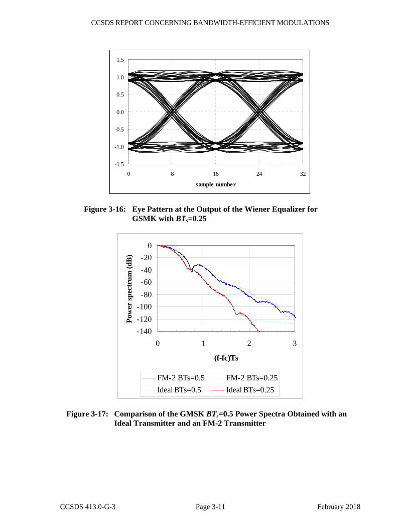
reduced by including a 3-tap equalizer (Wiener filter) with weights w0 = w2 = −0.0859984, w1 = 1.0116342, and delay equal to 2Ts between taps. The eye pattern at the output of the equalizer is shown in figure 3-16. The simulated power spectra obtained with an FM-2 implementation and with an IQ-L1 implementation with the above parameters are shown in figures 3-17 and 3-18.
-1.5
-1.0
-0.5
0.0
0.5
1.0
1.5
0 8 16 24 32
sample number
Figure 3-14: Eye Pattern at the Output of the Receiver Filter for GMSK with BTs=0.5
-1.5
-1.0
-0.5
0.0
0.5
1.0
1.5
0 8 16 24 32
sample number
Figure 3-15: Eye Pattern at the Output of the Receiver Filter for GMSK with BTs=0.25
CCSDS REPORT CONCERNING BANDWIDTH-EFFICIENT MODULATIONS
CCSDS 413.0-G-3 Page 3-11 February 2018
-1.5
-1.0
-0.5
0.0
0.5
1.0
1.5
0 8 16 24 32
sample number
Figure 3-16: Eye Pattern at the Output of the Wiener Equalizer for GSMK with BTs=0.25
-140-120-100-80-60-40-20
0
0 1 2 3
(f-fc)Ts
Pow
er sp
ectr
um (d
B)
FM-2 BTs=0.5 FM-2 BTs=0.25Ideal BTs=0.5 Ideal BTs=0.25
Figure 3-17: Comparison of the GMSK BTs=0.5 Power Spectra Obtained with an Ideal Transmitter and an FM-2 Transmitter
CCSDS REPORT CONCERNING BANDWIDTH-EFFICIENT MODULATIONS
CCSDS 413.0-G-3 Page 3-12 February 2018
-140-120-100-80-60-40-20
0
0 1 2 3
(f-fc)Ts
Pow
er sp
ectr
um (d
B)
IQ-L1 BTs=0.5 IQ-L1 BTs=0.25Ideal BTs=0.5 Ideal BTs=0.25
Figure 3-18: Comparison of the GMSK BTs=0.5 Power Spectra Obtained with an Ideal Transmitter and an IQ-L1 Transmitter
3.2 FILTERED OFFSET-QPSK
3.2.1 INTRODUCTION
Offset-QPSK (OQPSK) is a proven modulation technique which is robust and easily implemented. OQPSK receivers, typically employing integrate-and-dump type demodulators, are widely deployed by several international space agencies at ground stations operating downlinks in the S-band and X-band frequencies. With the use of proper filtering techniques, OQPSK modulation can meet the out-of-band emissions requirements of SFCG Recommendation 21-2R2 while still providing good BER performance with existing OQPSK receivers.
The majority of CCSDS studies performed on filtered OQPSK have examined baseband filtered implementations using Butterworth and Square Root Raised Cosine (SRRC) filters. These implementations avoid the additional cost, weight, and power loss (insertion loss plus filtering loss) associated with the use of RF filters, and have been shown to have good performance. However, filtered OQPSK with other filter types (including post-modulation filters) can also meet the high rate SFCG spectral mask requirements. This subsection details baseband filtered OQPSK implementations.
Two implementations of baseband filtered OQPSK modulation are described below: OQPSK with an I/Q modulator and OQPSK with a linear phase modulator, referred to as OQPSK/PM. Baseband filtered OQPSK with an I/Q modulator, filters the I and Q channel NRZ data signals and multiplies the filtered signals with in-phase and quadrature carrier
CCSDS REPORT CONCERNING BANDWIDTH-EFFICIENT MODULATIONS
CCSDS 413.0-G-3 Page 3-13 February 2018
signals. The baseband filtered OQPSK/PM signal is formed by mapping the I and Q NRZ data to a four-state phase signal, filtering the phase signal and then phase modulating a carrier with the filtered phase signal.
As with all modulations, the actual BER performance of filtered OQPSK is dependent on the receiver detection method used. An integrate-and-dump receiver with symbol-by-symbol detection is mathematically optimal for unfiltered OQPSK waveforms only. For filtered OQPSK, without the use of a complex maximum-likelihood receiver, the optimal receiver design would employ a receive filter precisely matched to the transmitter filter and an equalizer to remove intersymbol interference. For a modulation technique in which multiple alternative filter types have been recommended, this may seem to be a problem. Fortunately, in practice an integrate-and-dump filter receiver will provide good performance for most types of filtered OQPSK including those recommended.
Subsection 3.2.2 describes in detail the I/Q and linear phase modulator implementations of baseband filtered OQPSK. Subsection 3.3.3 presents various filtering options, including simulated power spectral density plots for three filter types.
3.2.2 MATHEMATICAL DEFINITION AND IMPLEMENTATION
Two modulator forms are commonly used for implementation of baseband filtered OQPSK (reference [5]). The linear phase modulator implementation is described in 3.2.2.1 and the I/Q modulator implementation is described in 3.2.2.2.5
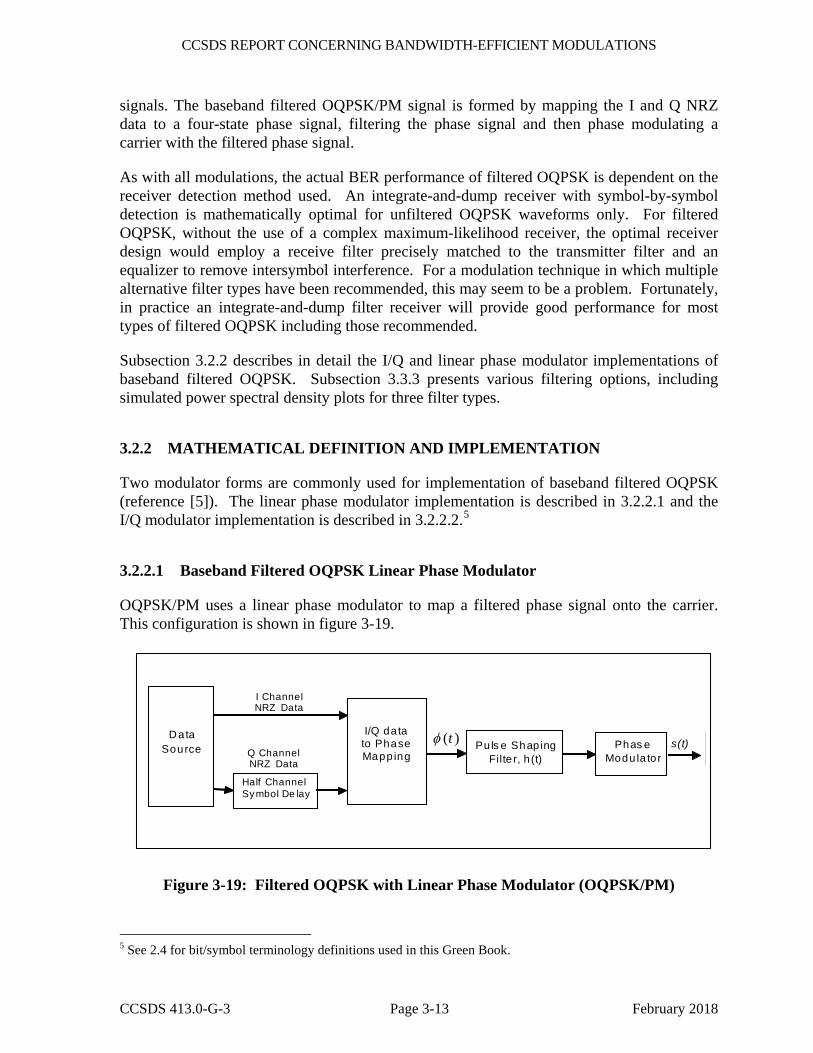
3.2.2.1 Baseband Filtered OQPSK Linear Phase Modulator
OQPSK/PM uses a linear phase modulator to map a filtered phase signal onto the carrier. This configuration is shown in figure 3-19.
s(t) )(tφ Phas e Modu la tor
Pu ls e Shap ingFilte r, h (t)
Half Channel Symbol De lay
D ata Source
I/Q data to Phase Mapp ing
I Channel NRZ Data
Q Channel NRZ Data
Figure 3-19: Filtered OQPSK with Linear Phase Modulator (OQPSK/PM)
5 See 2.4 for bit/symbol terminology definitions used in this Green Book.
CCSDS REPORT CONCERNING BANDWIDTH-EFFICIENT MODULATIONS
CCSDS 413.0-G-3 Page 3-14 February 2018
The input to the modulator is the in-phase (I) and Quadrature (Q) NRZ data streams. The Q-channel data stream is delayed by ½ symbol to create offset QPSK. The I and Q data is mapped to a phase signal which then goes through a pulse shaping filter.6 This is then used as an input to a linear phase modulator to produce the modulated output signal. The output of the modulator can be expressed as:
))(*)(2cos(2)( thttfPts c φπ +=
where
P = carrier power
fc = carrier frequency
�(t) is the phase output from the I-Q to phase mapping
h(t) is the impulse response of the pulse shaping filter
* denotes convolution
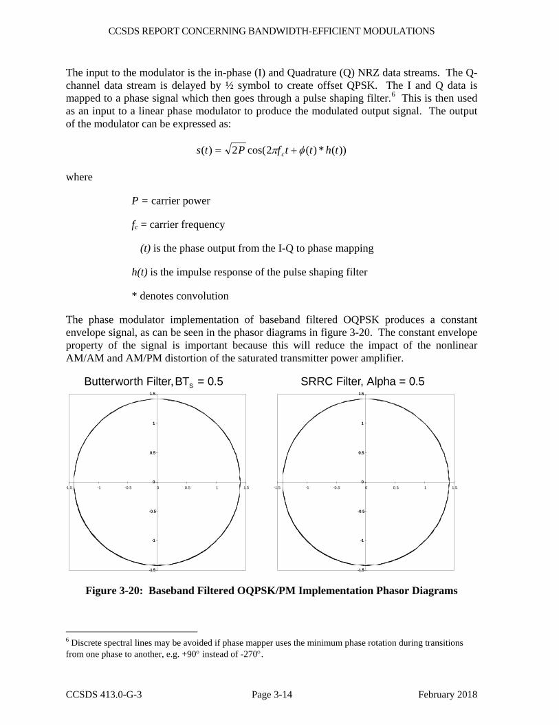
The phase modulator implementation of baseband filtered OQPSK produces a constant envelope signal, as can be seen in the phasor diagrams in figure 3-20. The constant envelope property of the signal is important because this will reduce the impact of the nonlinear AM/AM and AM/PM distortion of the saturated transmitter power amplifier.
-1.5
-1
-0.5
0
0.5
1
1.5
-1.5
-1
-0.5
0
0.5
1
1.5
-1.5
-1
-0.5
0
0.5
1
1.5
-1.5
-1
-0.5
0
0.5
1
1.5
-1.5 -1 -0.5 0 0.5 1 1.5 -1.5 -1 -0.5 0 0.5 1 1.5
Butterworth Filter, SRRC Filter, Alpha = 0.5BTs = 0.5
Figure 3-20: Baseband Filtered OQPSK/PM Implementation Phasor Diagrams
6 Discrete spectral lines may be avoided if phase mapper uses the minimum phase rotation during transitions from one phase to another, e.g. +90° instead of -270°.

CCSDS REPORT CONCERNING BANDWIDTH-EFFICIENT MODULATIONS
CCSDS 413.0-G-3 Page 3-15 February 2018
3.2.2.2 Baseband Filtered OQPSK I/Q Modulator
The second OQPSK implementation uses an I/Q modulator where the in-phase and quadrature carrier signals are amplitude modulated with a filtered NRZ data stream. This implementation is illustrated in figure 3-21.
yi(t)
yq(t)
+90°
I ChannelNRZ Data Pulse Shaping
Filter
DataSource
Half ChannelSymbol Delay
Pulse ShapingFilter
Q ChannelNRZ Data
s(t)+
90°
DataSource
Half ChannelSymbol Delay
Figure 3-21: Baseband Filtered OQPSK with I/Q Modulator
The input to the modulator is the I and Q NRZ data streams. The Q-channel data stream is delayed by half a channel symbol to create Offset QPSK. The output of the modulator can be expressed as:
s(t) = yi (t) sin(2πfct + φ) + yq (t) cos(2πfct + φ)
where yi(t) and yq(t) are filtered NRZ data and ϕ is the initial oscillator phase.
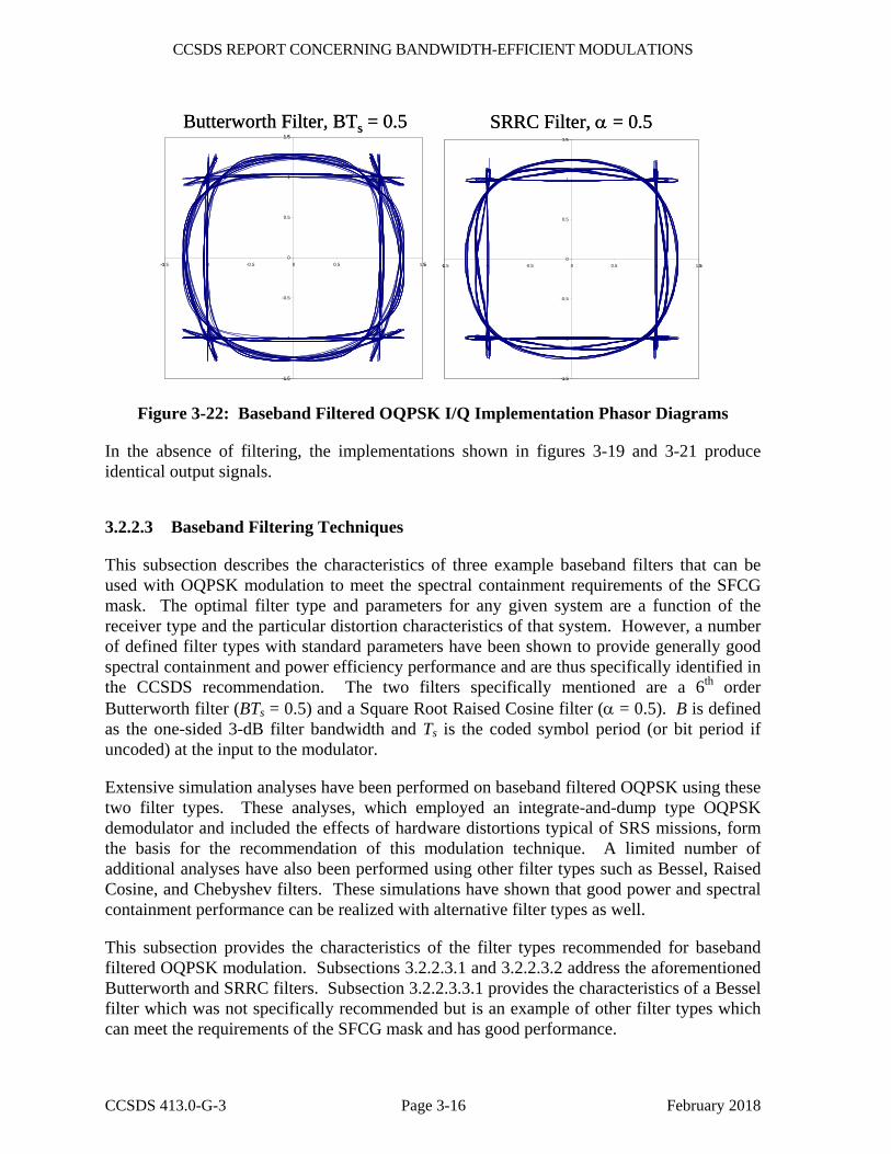
In this implementation, the magnitude variations due to filtering are present in the output signal and thus the output signal does not have a constant envelope. This is evident in the phasor diagrams in figure 3-22. As a result, this implementation will cause spectral re-growth and Inter-Symbol Interference (ISI) when used with a non-linear power amplifier.
CCSDS REPORT CONCERNING BANDWIDTH-EFFICIENT MODULATIONS
CCSDS 413.0-G-3 Page 3-16 February 2018
Butterworth Filter, BTs = 0.5 SRRC Filter, α = 0.5
-1.5
-1
-0.5
0
0.5
1
1.5
-1.5 -1 -0.5 0 0.5 1 1.5
-1.5
-1
-0.5
0
0.5
1
1.5
-1.5 -1 -0.5 0 0.5 1 1.5
Butterworth Filter, BTs = 0.5 SRRC Filter, α = 0.5
-1.5
-1
-0.5
0
0.5
1
1.5
-1.5 -1 -0.5 0 0.5 1 1.5
-1.5
-1
-0.5
0
0.5
1
1.5
-1.5 -1 -0.5 0 0.5 1 1.5
Figure 3-22: Baseband Filtered OQPSK I/Q Implementation Phasor Diagrams
In the absence of filtering, the implementations shown in figures 3-19 and 3-21 produce identical output signals.
3.2.2.3 Baseband Filtering Techniques
This subsection describes the characteristics of three example baseband filters that can be used with OQPSK modulation to meet the spectral containment requirements of the SFCG mask. The optimal filter type and parameters for any given system are a function of the receiver type and the particular distortion characteristics of that system. However, a number of defined filter types with standard parameters have been shown to provide generally good spectral containment and power efficiency performance and are thus specifically identified in the CCSDS recommendation. The two filters specifically mentioned are a 6th order Butterworth filter (BTs = 0.5) and a Square Root Raised Cosine filter (α = 0.5). B is defined as the one-sided 3-dB filter bandwidth and Ts is the coded symbol period (or bit period if uncoded) at the input to the modulator.
Extensive simulation analyses have been performed on baseband filtered OQPSK using these two filter types. These analyses, which employed an integrate-and-dump type OQPSK demodulator and included the effects of hardware distortions typical of SRS missions, form the basis for the recommendation of this modulation technique. A limited number of additional analyses have also been performed using other filter types such as Bessel, Raised Cosine, and Chebyshev filters. These simulations have shown that good power and spectral containment performance can be realized with alternative filter types as well.
This subsection provides the characteristics of the filter types recommended for baseband filtered OQPSK modulation. Subsections 3.2.2.3.1 and 3.2.2.3.2 address the aforementioned Butterworth and SRRC filters. Subsection 3.2.2.3.3.1 provides the characteristics of a Bessel filter which was not specifically recommended but is an example of other filter types which can meet the requirements of the SFCG mask and has good performance.
CCSDS REPORT CONCERNING BANDWIDTH-EFFICIENT MODULATIONS
CCSDS 413.0-G-3 Page 3-17 February 2018
The Butterworth and Bessel filters are implemented as Infinite Impulse Response (IIR) filters, while the SRRC filter is implemented as a transversal Finite Impulse Response (FIR) filter. The implementation fidelity of these filters depends on the length of the filter, the sampling rate, and the amplitude quantization. The characteristics and design details of these filters is well documented in reference [6] and other textbooks.
3.2.2.3.1 Baseband Filtered OQPSK with a Butterworth Filter
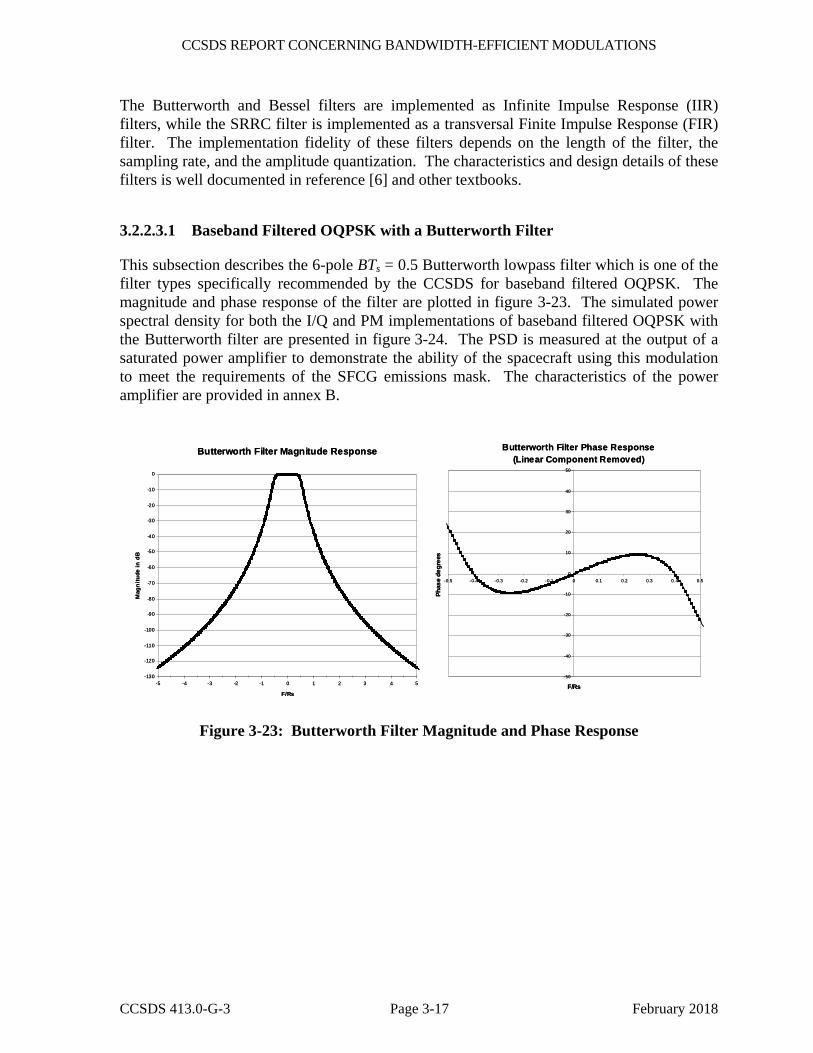
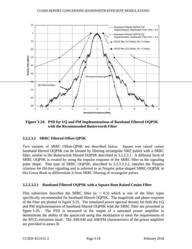
This subsection describes the 6-pole BTs = 0.5 Butterworth lowpass filter which is one of the filter types specifically recommended by the CCSDS for baseband filtered OQPSK. The magnitude and phase response of the filter are plotted in figure 3-23. The simulated power spectral density for both the I/Q and PM implementations of baseband filtered OQPSK with the Butterworth filter are presented in figure 3-24. The PSD is measured at the output of a saturated power amplifier to demonstrate the ability of the spacecraft using this modulation to meet the requirements of the SFCG emissions mask. The characteristics of the power amplifier are provided in annex B.
Butterworth Filter Magnitude Response
-130
-120
-110
-100
-90
-80
-70
-60
-50
-40
-30
-20
-10
0
-5 -4 -3 -2 -1 0 1 2 3 4 5
F/Rs
Mag
nitu
de in
dB
Butterworth Filter Phase Response (Linear Component Removed)
-50
-40
-30
-20
-10
0
10
20
30
40
50
-0.5 -0.4 -0.3 -0.2 -0.1 0 0.1 0.2 0.3 0. 4 0.5
F/Rs
Phas
e de
gree
s
Figure 3-23: Butterworth Filter Magnitude and Phase Response
CCSDS REPORT CONCERNING BANDWIDTH-EFFICIENT MODULATIONS
CCSDS 413.0-G-3 Page 3-18 February 2018
-90
-80
-70
-60
-50
-40
-30
-20
-10
0
10
-5 -4 -3 -2 -1 0 1 2 3 4 5
Normalized Frequency (F/Rs)
Rel
ativ
e PS
D (d
B/H
z)Baseband Filtered OQPSK PMImplementation, Butterworth Filter, BTs = 0.5
Baseband Filtered OQPSK I/QImplementation, Butterworth Filter, BTs = 0.5
SFCG Rec 21-2 Mask, Rs < 2 Msps
SFCG Rec 21-2 Mask, Rs > 2 Msps
I/Q Implementation
PM Implementation
Figure 3-24: PSD for I/Q and PM Implementations of Baseband Filtered OQPSK with the Recommended Butterworth Filter
3.2.2.3.2 SRRC Filtered Offset-QPSK
Two variants of SRRC Offset-QPSK are described below. Square root raised cosine baseband filtered OQPSK can be formed by filtering rectangular NRZ pulses with a SRRC filter, similar to the Butterworth filtered OQPSK described in 3.2.2.3.1. A different form of SRRC OQPSK is created by using the impulse response of the SRRC filter as the signaling pulse shape. This type of SRRC OQPSK, described in 3.2.2.3.2.2, satisfies the Nyquist criterion for ISI-free signaling and is referred to as Nyquist pulse-shaped SRRC OQPSK in this Green Book to differentiate it from SRRC filtering of rectangular pulses.
3.2.2.3.2.1 Baseband Filtered OQPSK with a Square Root Raised Cosine Filter
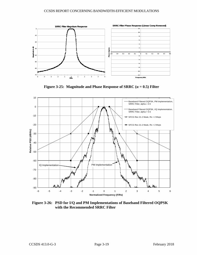
This subsection describes the SRRC filter (α = 0.5) which is one of the filter types specifically recommended for baseband filtered OQPSK. The magnitude and phase response of the filter are plotted in figure 3-25. The simulated power spectral density for both the I/Q and PM implementations of baseband filtered OQPSK with the SRRC filter are presented in figure 3-26. The PSD is measured at the output of a saturated power amplifier to demonstrate the ability of the spacecraft using this modulation to meet the requirements of the SFCG emissions mask. The AM/AM and AM/PM characteristics of the power amplifier are provided in annex B.
CCSDS REPORT CONCERNING BANDWIDTH-EFFICIENT MODULATIONS
CCSDS 413.0-G-3 Page 3-19 February 2018
SRRC Filter Magniture Response
-70
-60
-50
-40
-30
-20
-10
0
-5 -4 -3 -2 -1 0 1 2 3 4 5F/Rs
Mag
nitu
de in
dB
SRRC Filter Phase Response (Linear Comp Removed)
-12
-10
-8
-6
-4
-2
0
2
4
6
8
10
12
-0.5 -0.4 -0.3 -0.2 -0.1 0 0.1 0.2 0.3 0.4 0.5
Frequency MHz
Phas
e de
gree
s
SRRC Filter Magniture Response
-70
-60
-50
-40
-30
-20
-10
0
-5 -4 -3 -2 -1 0 1 2 3 4 5F/Rs
Mag
nitu
de in
dB
SRRC Filter Phase Response (Linear Comp Removed)
-12
-10
-8
-6
-4
-2
0
2
4
6
8
10
12
-0.5 -0.4 -0.3 -0.2 -0.1 0 0.1 0.2 0.3 0.4 0.5
Frequency MHz
Phas
e de
gree
s
Figure 3-25: Magnitude and Phase Response of SRRC (α = 0.5) Filter
-90
-80
-70
-60
-50
-40
-30
-20
-10
0
10
-6 -5 -4 -3 -2 -1 0 1 2 3 4 5 6Normalized Frequency (F/Rs)
Rel
ativ
ePS
D(d
B/H
z)
Baseband Filtered OQPSK, PM Implementation,SRRC Filter, alpha = 0.5
Baseband Filtered OQPSK, I/Q Implementation,SRRC Filter, alpha = 0.5
SFCG Rec 21-2 Mask, Rs < 2 Msps
SFCG Rec 21-2 Mask, Rs > 2 Msps
PM ImplementationIQ Implementation
Figure 3-26: PSD for I/Q and PM Implementations of Baseband Filtered OQPSK with the Recommended SRRC Filter
CCSDS REPORT CONCERNING BANDWIDTH-EFFICIENT MODULATIONS
CCSDS 413.0-G-3 Page 3-20 February 2018
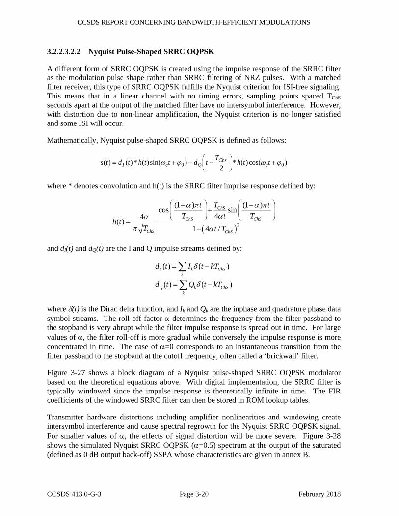
3.2.2.3.2.2 Nyquist Pulse-Shaped SRRC OQPSK
A different form of SRRC OQPSK is created using the impulse response of the SRRC filter as the modulation pulse shape rather than SRRC filtering of NRZ pulses. With a matched filter receiver, this type of SRRC OQPSK fulfills the Nyquist criterion for ISI-free signaling. This means that in a linear channel with no timing errors, sampling points spaced TChS seconds apart at the output of the matched filter have no intersymbol interference. However, with distortion due to non-linear amplification, the Nyquist criterion is no longer satisfied and some ISI will occur.
Mathematically, Nyquist pulse-shaped SRRC OQPSK is defined as follows:
)cos()(*2
)sin()(*)()( 00 ϕωϕω +⎟⎠⎞
⎜⎝⎛ −++= tthTtdtthtdts c
ChsQcI
where * denotes convolution and h(t) is the SRRC filter impulse response defined by:
( )2
(1 ) (1 )cos sin44( )
1 4 /
ChS
ChS ChS
ChS ChS
Tt tT t T
h tT t T
α π α παα
π α
⎛ ⎞ ⎛ ⎞+ −+⎜ ⎟ ⎜ ⎟⎝ ⎠ ⎝ ⎠=
−
and dI(t) and dQ(t) are the I and Q impulse streams defined by:
( ) ( )
( ) ( )
I k ChSk
Q k ChSk
d t I t kT
d t Q t kT
δ
δ
= −
= −
∑
∑
where δ(t) is the Dirac delta function, and Ik and Qk are the inphase and quadrature phase data symbol streams. The roll-off factor α determines the frequency from the filter passband to the stopband is very abrupt while the filter impulse response is spread out in time. For large values of α, the filter roll-off is more gradual while conversely the impulse response is more concentrated in time. The case of α=0 corresponds to an instantaneous transition from the filter passband to the stopband at the cutoff frequency, often called a ‘brickwall’ filter.
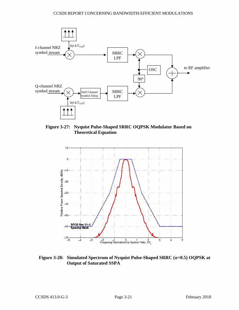
Figure 3-27 shows a block diagram of a Nyquist pulse-shaped SRRC OQPSK modulator based on the theoretical equations above. With digital implementation, the SRRC filter is typically windowed since the impulse response is theoretically infinite in time. The FIR coefficients of the windowed SRRC filter can then be stored in ROM lookup tables.
Transmitter hardware distortions including amplifier nonlinearities and windowing create intersymbol interference and cause spectral regrowth for the Nyquist SRRC OQPSK signal. For smaller values of α, the effects of signal distortion will be more severe. Figure 3-28 shows the simulated Nyquist SRRC OQPSK (α=0.5) spectrum at the output of the saturated (defined as 0 dB output back-off) SSPA whose characteristics are given in annex B.
CCSDS REPORT CONCERNING BANDWIDTH-EFFICIENT MODULATIONS
CCSDS 413.0-G-3 Page 3-21 February 2018
I-channel NRZsymbol stream SRRC
LPF
to RF amplifier
90°
OSC
SRRCLPF
Half ChannelSymbol Delay
Q-channel NRZsymbol stream
δ(t-kTChS)
δ(t-kTChS)
Figure 3-27: Nyquist Pulse-Shaped SRRC OQPSK Modulator Based on Theoretical Equation
Figure 3-28: Simulated Spectrum of Nyquist Pulse-Shaped SRRC (α=0.5) OQPSK at Output of Saturated SSPA
CCSDS REPORT CONCERNING BANDWIDTH-EFFICIENT MODULATIONS
CCSDS 413.0-G-3 Page 3-22 February 2018
3.2.2.3.3 Baseband Filtered OQPSK with Other Filter Types
As indicated above, Butterworth and/or SRRC filters are not necessarily optimum for use in baseband filtered OQPSK systems. While it would be impossible to document the performance of all possible filters, the performance of Bessel-filtered OQPSK is addressed in the following subsection as an example.
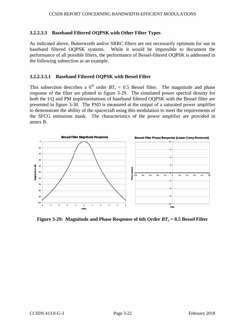
3.2.2.3.3.1 Baseband Filtered OQPSK with Bessel Filter
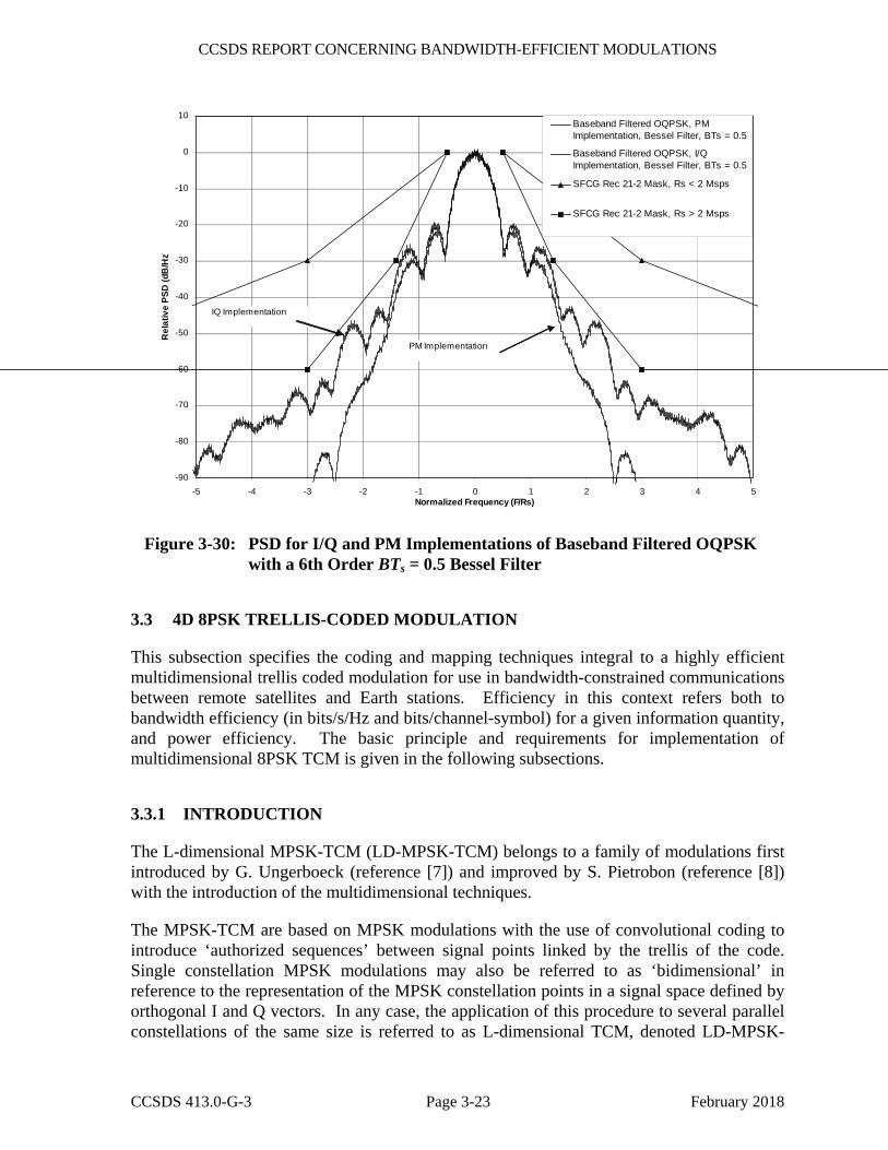
This subsection describes a 6th order BTs = 0.5 Bessel filter. The magnitude and phase response of the filter are plotted in figure 3-29. The simulated power spectral density for both the I/Q and PM implementations of baseband filtered OQPSK with the Bessel filter are presented in figure 3-30. The PSD is measured at the output of a saturated power amplifier to demonstrate the ability of the spacecraft using this modulation to meet the requirements of the SFCG emissions mask. The characteristics of the power amplifier are provided in annex B.
Bessel Filter Magnitude Response
-100
-90
-80
-70
-60
-50
-40
-30
-20
-10
0
-5 -4 -3 -2 -1 0 1 2 3 4 5
F/Rs
Mag
nitu
de in
dB
Bessel Filter Phase Response (Linear Comp Removed)
-12
-9
-6
-3
0
3
6
9
12
-0.5 -0.4 -0.3 -0.2 -0.1 0 0.1 0.2 0.3 0.4 0.5
F/Rs
Phas
e de
gree
s
Bessel Filter Magnitude Response
-100
-90
-80
-70
-60
-50
-40
-30
-20
-10
0
-5 -4 -3 -2 -1 0 1 2 3 4 5
F/Rs
Mag
nitu
de in
dB
Bessel Filter Phase Response (Linear Comp Removed)
-12
-9
-6
-3
0
3
6
9
12
-0.5 -0.4 -0.3 -0.2 -0.1 0 0.1 0.2 0.3 0.4 0.5
F/Rs
Phas
e de
gree
s
Figure 3-29: Magnitude and Phase Response of 6th Order BTs = 0.5 Bessel Filter
CCSDS REPORT CONCERNING BANDWIDTH-EFFICIENT MODULATIONS
CCSDS 413.0-G-3 Page 3-23 February 2018
-90
-80
-70
-60
-50
-40
-30
-20
-10
0
10
-5 -4 -3 -2 -1 0 1 2 3 4 5Normalized Frequency (F/Rs)
Rel
ativ
e PS
D (d
B/H
z)
Baseband Filtered OQPSK, PMImplementation, Bessel Filter, BTs = 0.5
Baseband Filtered OQPSK, I/QImplementation, Bessel Filter, BTs = 0.5
SFCG Rec 21-2 Mask, Rs < 2 Msps
SFCG Rec 21-2 Mask, Rs > 2 Msps
PM Implementation
IQ Implementation
Figure 3-30: PSD for I/Q and PM Implementations of Baseband Filtered OQPSK with a 6th Order BTs = 0.5 Bessel Filter
3.3 4D 8PSK TRELLIS-CODED MODULATION
This subsection specifies the coding and mapping techniques integral to a highly efficient multidimensional trellis coded modulation for use in bandwidth-constrained communications between remote satellites and Earth stations. Efficiency in this context refers both to bandwidth efficiency (in bits/s/Hz and bits/channel-symbol) for a given information quantity, and power efficiency. The basic principle and requirements for implementation of multidimensional 8PSK TCM is given in the following subsections.
3.3.1 INTRODUCTION
The L-dimensional MPSK-TCM (LD-MPSK-TCM) belongs to a family of modulations first introduced by G. Ungerboeck (reference [7]) and improved by S. Pietrobon (reference [8]) with the introduction of the multidimensional techniques.
The MPSK-TCM are based on MPSK modulations with the use of convolutional coding to introduce ‘authorized sequences’ between signal points linked by the trellis of the code. Single constellation MPSK modulations may also be referred to as ‘bidimensional’ in reference to the representation of the MPSK constellation points in a signal space defined by orthogonal I and Q vectors. In any case, the application of this procedure to several parallel constellations of the same size is referred to as L-dimensional TCM, denoted LD-MPSK-
CCSDS REPORT CONCERNING BANDWIDTH-EFFICIENT MODULATIONS
CCSDS 413.0-G-3 Page 3-24 February 2018
TCM (with L > 1 and M ≥ 8). The trellis is constructed to maximize the minimum Euclidian distance between different paths originating and merging to the same state. The construction of the optimum trellis code and partitioning for the M points in the constellation is based on heuristic rules proposed in references [7] and [8].
With 4D-8PSK-TCM, the combination of convolutional coding, multiphase modulation and multidimensional techniques offers a substantial power gain together with bandwidth conservation or reduction, in comparison to their separate utilization as it is done frequently with binary or quaternary modulations (i.e., sequential implementation of convolutional coding). The result is an improvement of the performances in terms of BER versus signal to noise ratio for the same or better bandwidth efficiency, compared with the uncoded OQPSK or QPSK modulations.
Example: Assuming the bit rate Rb of input data equal to 100 Mbps, the 4D-8PSK-TCM channel symbol rate is 50 Ms/s for 2 bits/channel-symbol or 40 Ms/s for 2.5 bits/channel-symbol.
3.3.2 4D-8PSK-TCM CODER
The 4D-8PSK trellis-coded modulator consists of a serial-to-parallel converter, a differential coder, a trellis encoder (convolutional coder), a constellation mapper, and an 8PSK modulator (see figure 3-31). In this figure, wi (with index i = 1, … , m) represent the uncoded bits and xj (with index j = 0, … , m) are the coded bits. The trellis encoder is based on a 64-state systematic convolutional coder and can be considered as the inner code if an outer block code is introduced. Carrier phase ambiguity is resolved by the use of a differential coder located prior to the trellis encoder. Spectral efficiencies of 2, 2.25, 2.5, and 2.75 bits/channel-symbol are achieved with four possible architectures of the constellation mapper. The output switch addresses successively one of the four symbols ( Z(0) – Z(3) ) from the constellation mapper to the 8PSK modulator.
The present standard is based on the use of a 4D-8PSK-TCM characterized by the following parameters:
– size of the constellation: M=8 phase states (8PSK);
– number of signal set constituents: L=4 (shown as Z(0) … Z(3) in figure 3-31);
– number of states for the trellis encoder: 64;
– rate of the convolutional coder used for the construction of the trellis: R=3/4;
– rate of the modulation: Rm=m/(m+1) selectable to 8/9, 9/10, 10/11, or 11/12;
– efficiency of the modulation:
• Reff=2 bits per channel-symbol (for Rm=8/9);
• Reff=2.25 bits per channel-symbol (for Rm=9/10);

CCSDS REPORT CONCERNING BANDWIDTH-EFFICIENT MODULATIONS
CCSDS 413.0-G-3 Page 3-25 February 2018
• Reff=2.5 bits per channel-symbol (for Rm=10/11);
• Reff=2.75 bits per channel-symbol (for Rm=11/12).
Seria
l to
Para
llel c
onve
rsio
n
Con
stel
latio
n m
appe
r
wi
ConvolutionalCoder R=3/4
xj (j above 3)
x3x2x1
x0 CarrierGenerator
ModulatedCarrier
Dat
a In
Diff
eren
tialc
oder
Z(0)
Z(1)
Z(2)
Z(3)
Seria
l to
Para
llel c
onve
rsio
n
Con
stel
latio
n m
appe
r
wi
ConvolutionalCoder R=3/4ConvolutionalCoder R=3/4
xj (j above 3)
x3x2x1
x0 CarrierGenerator
ModulatedCarrier
Dat
a In
Diff
eren
tialc
oder
Z(0)
Z(1)
Z(2)
Z(3)
Z(0)
Z(1)
Z(2)
Z(3)
Figure 3-31: Structure of the 4D 8PSK-TCM Coder/Mapper
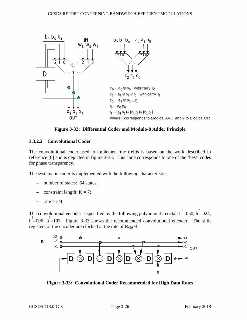
3.3.2.1 Differential Coder
The differential coder depicted in figure 3-32 is used to eliminate phase ambiguity on carrier synchronization for each modulation efficiency. Table 3-1 gives the bit reference at input and output of the differential coder in each case.
Table 3-1: Bit Mapping for Differential Coder
Efficiencies in bits /channel-symbol
2 2.25 2.5 2.75
bit IN bit OUT bit IN bit OUT bit IN bit OUT bit IN bit OUT
w1 x1 w2 x2 w3 x3 w4 x4
w5 x5 w6 x6 w7 x7 w8 x8
w8 x8 w9 x9 w10 x10 w11 x11
An example of differential encoder connections is given in figure 3-32 for the 2 bits/channel-symbol case. The structure of the modulo 8 adder is also shown; it is applicable to both the coder mapper and differential coder.
CCSDS REPORT CONCERNING BANDWIDTH-EFFICIENT MODULATIONS
CCSDS 413.0-G-3 Page 3-26 February 2018
++
2
22
1
11 0
0
0
w 8 w 5 w 1
x8 x5 x1
b8 b5 b1
D
IN
OUT
a2 a1 a0b2 b1 b0
c2 c1 c0
+
2 1 0 2 1 0
2 1 0
( ) ( ) ( )OR logical a to and AND,logical a to scorrespond . where
r.br.ab.arb.ar
rbacrcarry withrbac
rcarry withbac
0101111
000
1222
10111
0000
+
++=
=
⊕⊕=
⊕⊕=
⊕=
Figure 3-32: Differential Coder and Modulo-8 Adder Principle
3.3.2.2 Convolutional Coder
The convolutional coder used to implement the trellis is based on the work described in reference [8] and is depicted in figure 3-33. This code corresponds to one of the ‘best’ codes for phase transparency.
The systematic coder is implemented with the following characteristics:
– number of states: 64 states;
– constraint length: K = 7;
– rate = 3/4.
The convolutional encoder is specified by the following polynomial in octal: h3=050, h
2=024,
h1=006, h
0=103. Figure 3-33 shows the recommended convolutional encoder. The shift
registers of the encoder are clocked at the rate of RChS/4.
D
IN OUT
x0
x1 x2 x3
x1
x3 x2
D D D D D
Figure 3-33: Convolutional Coder Recommended for High Data Rates
CCSDS REPORT CONCERNING BANDWIDTH-EFFICIENT MODULATIONS
CCSDS 413.0-G-3 Page 3-27 February 2018
The number of coded bits is the same for the four modulation efficiencies (i.e., the same structure is used for 2, 2.25, 2.5, and 2.75 bits/channel-symbol), only the number of uncoded bits is changed. The advantage of this coder is its optimized performance and the reduced internal rate which is equal to 1/8, 1/9, 1/10, or 1/11 of the information rate.
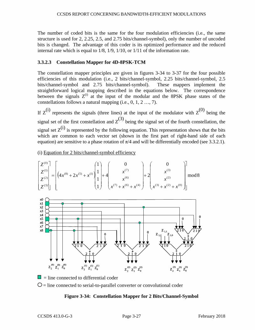
3.3.2.3 Constellation Mapper for 4D-8PSK-TCM
The constellation mapper principles are given in figures 3-34 to 3-37 for the four possible efficiencies of this modulation (i.e., 2 bits/channel-symbol, 2.25 bits/channel-symbol, 2.5 bits/channel-symbol and 2.75 bits/channel-symbol). These mappers implement the straightforward logical mapping described in the equations below. The correspondence between the signals Z(i) at the input of the modular and the 8PSK phase states of the constellations follows a natural mapping (i.e., 0, 1, 2 …, 7).
If Z(i) represents the signals (three lines) at the input of the modulator with Z(0) being the
signal set of the first constellation and Z(3) being the signal set of the fourth constellation, the
signal set Z(i) is represented by the following equation. This representation shows that the bits which are common to each vector set (shown in the first part of right-hand side of each equation) are sensitive to a phase rotation of π/4 and will be differentially encoded (see 3.3.2.1).
(i) Equation for 2 bits/channel-symbol efficiency
( ) 8mod
0
2
0
4
1111
24
)0()2()3(
)2(
)3(
)4()6()7(
)6(
)7()1()5()8(
)3(
)2(
)1(
)0(
⎥⎥⎥⎥⎥
⎦
⎤
⎢⎢⎢⎢⎢
⎣
⎡
⎟⎟⎟⎟⎟
⎠
⎞
⎜⎜⎜⎜⎜
⎝
⎛
++
+
⎟⎟⎟⎟⎟
⎠
⎞
⎜⎜⎜⎜⎜
⎝
⎛
++
+
⎟⎟⎟⎟⎟
⎠
⎞
⎜⎜⎜⎜⎜
⎝
⎛
++=
⎥⎥⎥⎥⎥
⎦
⎤
⎢⎢⎢⎢⎢
⎣
⎡
xxxxx
xxxxx
xxx
ZZZZ
x0x1x2x3x4x5x6x7x8
Z 1,2
Z 1,1Z 1,0
0
+
+
+ +
2 1 0
2 1 0 2 1 0 2 1 0 2 1 0 2 1 0 2 1 0
2 1 0
2 1 0
2 1 0 2 1 0 2 1 0
0 0
0
Z (1)
Z (1)
Z (1)
2 1 0 Z (2)
Z (2)
Z (2)
2 1 0Z
(0)Z
(0)Z
(0)
2 1 0 Z (3)
Z (3)
Z (3)
2 1 0
x0x1x2x3x4x5x6x7x8
Z 1,2
Z 1,1Z 1,0
0
+
+
+ +
2 1 0
2 1 0 2 1 0 2 1 0 2 1 0 2 1 0 2 1 0
2 1 0
2 1 0
2 1 0 2 1 0 2 1 0
0 0
0
Z (1)
Z (1)
Z (1)
2 1 0 Z (2)
Z (2)
Z (2)
2 1 0Z
(0)Z
(0)Z
(0)
2 1 0 Z (3)
Z (3)
Z (3)
2 1 0 = line connected to differential coder = line connected to serial-to-parallel converter or convolutional coder
Figure 3-34: Constellation Mapper for 2 Bits/Channel-Symbol
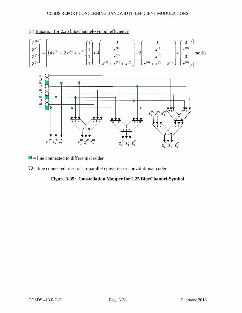
CCSDS REPORT CONCERNING BANDWIDTH-EFFICIENT MODULATIONS
CCSDS 413.0-G-3 Page 3-28 February 2018
(ii) Equation for 2.25 bits/channel-symbol efficiency
( ) 8mod0
00
2
0
4
1111
24
)0(
)0(
)1()3()4(
)3(
)4(
)5()7()8(
)7(
)8()2()6()9(
)3(
)2(
)1(
)0(
⎥⎥⎥⎥
⎦
⎤
⎢⎢⎢⎢
⎣
⎡
⎟⎟⎟⎟⎟
⎠
⎞
⎜⎜⎜⎜⎜
⎝
⎛
+
⎟⎟⎟⎟⎟
⎠
⎞
⎜⎜⎜⎜⎜
⎝
⎛
++
+
⎟⎟⎟⎟⎟
⎠
⎞
⎜⎜⎜⎜⎜
⎝
⎛
++
+
⎟⎟⎟⎟⎟
⎠
⎞
⎜⎜⎜⎜⎜
⎝
⎛
++=
⎥⎥⎥⎥
⎦
⎤
⎢⎢⎢⎢
⎣
⎡
x
x
xxxxx
xxxxx
xxx
ZZZZ
x0x1x2x3x4x5x6x7x8x9
0
+
+
2 1 0
2 1 0 2 1 0
2 1 0
2 1 0
+2 1 0 2 1 0
2 1 0 +2 1 0 2 1 0
2 1 02 1 0
0
0
Z (1)
Z (1)
Z (1)
2 1 0 Z (2)
Z (2)
Z (2)
2 1 0Z
(0)Z
(0)Z
(0)
2 1 0Z
(3)Z
(3)Z
(3)2 1 0
Z (1)
Z (1)
Z (1)
2 1 0
x0x1x2x3x4x5x6x7x8x9
0
+
+
2 1 0
2 1 0 2 1 0
2 1 0
2 1 0
+2 1 0 2 1 0
2 1 0 +2 1 0 2 1 0
2 1 02 1 0
0
0
Z (1)
Z (1)
Z (1)
2 1 0 Z (2)
Z (2)
Z (2)
2 1 0Z
(0)Z
(0)Z
(0)
2 1 0Z
(3)Z
(3)Z
(3)2 1 0
Z (1)
Z (1)
Z (1)
2 1 0
= line connected to differential coder
= line connected to serial-to-parallel converter or convolutional coder
Figure 3-35: Constellation Mapper for 2.25 Bits/Channel-Symbol
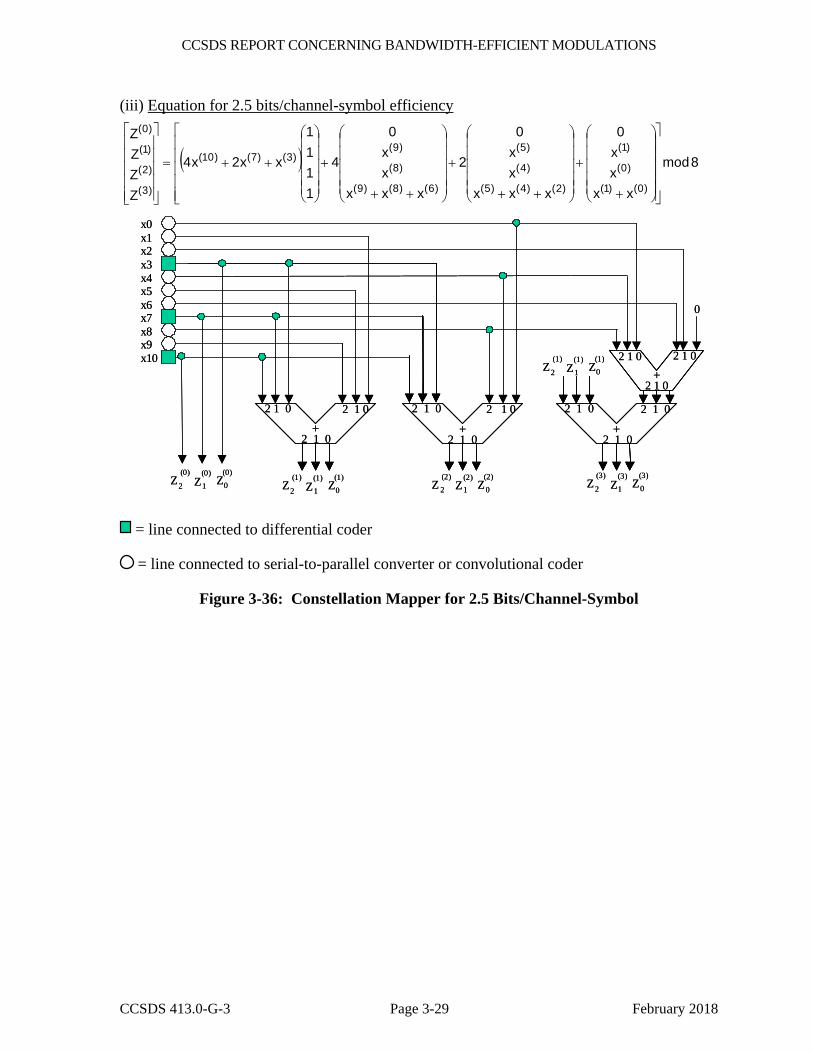
CCSDS REPORT CONCERNING BANDWIDTH-EFFICIENT MODULATIONS
CCSDS 413.0-G-3 Page 3-29 February 2018
(iii) Equation for 2.5 bits/channel-symbol efficiency
( ) 8mod
xxxx0
xxxxx0
2
xxxxx0
4
1111
xx2x4
ZZZZ
)0()1(
)0(
)1(
)2()4()5(
)4(
)5(
)6()8()9(
)8(
)9()3()7()10(
)3(
)2(
)1(
)0(
⎥⎥⎥⎥⎥
⎦
⎤
⎢⎢⎢⎢⎢
⎣
⎡
⎟⎟⎟⎟⎟
⎠
⎞
⎜⎜⎜⎜⎜
⎝
⎛
+
+
⎟⎟⎟⎟⎟
⎠
⎞
⎜⎜⎜⎜⎜
⎝
⎛
++
+
⎟⎟⎟⎟⎟
⎠
⎞
⎜⎜⎜⎜⎜
⎝
⎛
++
+
⎟⎟⎟⎟⎟
⎠
⎞
⎜⎜⎜⎜⎜
⎝
⎛
++=
⎥⎥⎥⎥⎥
⎦
⎤
⎢⎢⎢⎢⎢
⎣
⎡
x0x1x2x3x4x5x6x7x8x9x10
0
+
+
+ +
2 1 0
2 1 0 2 1 0 2 1 0 2 1 0 2 1 0 2 1 0
2 1 0
2 1 0
2 1 0 2 1 0 2 1 0
Z (0)
Z (0)
Z (0)
2 1 0 Z (1)
Z (1)
Z (1)
2 1 0 Z (2)
Z (2)
Z (2)
2 1 0 Z (3)
Z (3)
Z (3)
2 1 0
Z (1)
Z (1)
Z (1)
2 1 0
x0x1x2x3x4x5x6x7x8x9x10
0
+
+
+ +
2 1 0
2 1 0 2 1 0 2 1 0 2 1 0 2 1 0 2 1 0
2 1 0
2 1 0
2 1 0 2 1 0 2 1 0
Z (0)
Z (0)
Z (0)
2 1 0 Z (1)
Z (1)
Z (1)
2 1 0 Z (2)
Z (2)
Z (2)
2 1 0 Z (3)
Z (3)
Z (3)
2 1 0
Z (1)
Z (1)
Z (1)
2 1 0
= line connected to differential coder
= line connected to serial-to-parallel converter or convolutional coder
Figure 3-36: Constellation Mapper for 2.5 Bits/Channel-Symbol
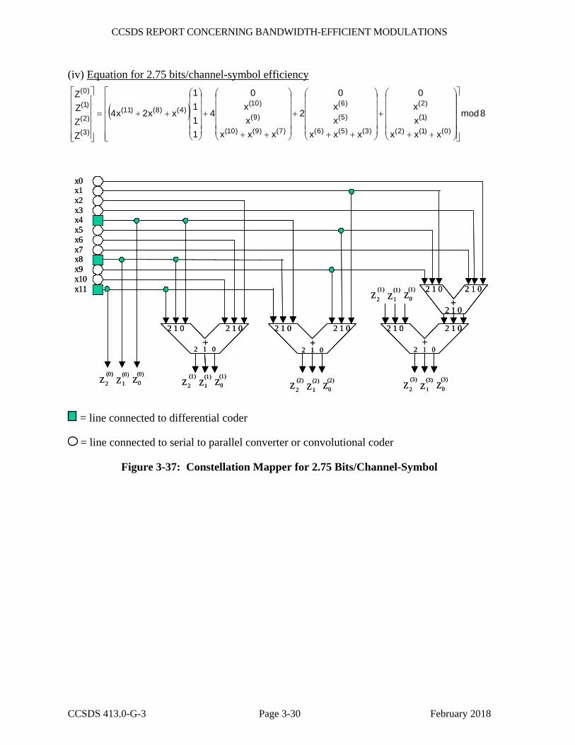
CCSDS REPORT CONCERNING BANDWIDTH-EFFICIENT MODULATIONS
CCSDS 413.0-G-3 Page 3-30 February 2018
(iv) Equation for 2.75 bits/channel-symbol efficiency
( ) 8mod
xxxxx0
xxxxx0
2
xxxxx
0
4
1111
xx2x4
ZZZZ
)0()1()2(
)1(
)2(
)3()5()6(
)5(
)6(
)7()9()10(
)9(
)10()4()8()11(
)3(
)2(
)1(
)0(
⎥⎥⎥⎥⎥
⎦
⎤
⎢⎢⎢⎢⎢
⎣
⎡
⎟⎟⎟⎟⎟
⎠
⎞
⎜⎜⎜⎜⎜
⎝
⎛
++
+
⎟⎟⎟⎟⎟
⎠
⎞
⎜⎜⎜⎜⎜
⎝
⎛
++
+
⎟⎟⎟⎟⎟
⎠
⎞
⎜⎜⎜⎜⎜
⎝
⎛
++
+
⎟⎟⎟⎟⎟
⎠
⎞
⎜⎜⎜⎜⎜
⎝
⎛
++=
⎥⎥⎥⎥⎥
⎦
⎤
⎢⎢⎢⎢⎢
⎣
⎡
x0x1x2x3x4x5x6x7x8x9x10x11
Z (1)
Z (1)
Z (1)
+
+ +
2 1 0
2 1 0 2 1 0 2 1 0 2 1 0 2 1 0 2 1 0
2 1 0
2 1 0
2 1 0
2 1 0 Z (2)
Z (2)
Z (2)
2 1 0Z
(0)Z
(0)Z
(0)2 1 0 Z
(3)Z
(3)Z
(3)
2 1 0
Z (1)
Z (1)
Z (1)
2 1 0
2 1 0+
2 1 0
x0x1x2x3x4x5x6x7x8x9x10x11
Z (1)
Z (1)
Z (1)
+
+ +
2 1 0
2 1 0 2 1 0 2 1 0 2 1 0 2 1 0 2 1 0
2 1 0
2 1 0
2 1 0
2 1 0 Z (2)
Z (2)
Z (2)
2 1 0Z
(0)Z
(0)Z
(0)2 1 0 Z
(3)Z
(3)Z
(3)
2 1 0
Z (1)
Z (1)
Z (1)
2 1 0
2 1 0+
2 1 0
= line connected to differential coder
= line connected to serial to parallel converter or convolutional coder
Figure 3-37: Constellation Mapper for 2.75 Bits/Channel-Symbol
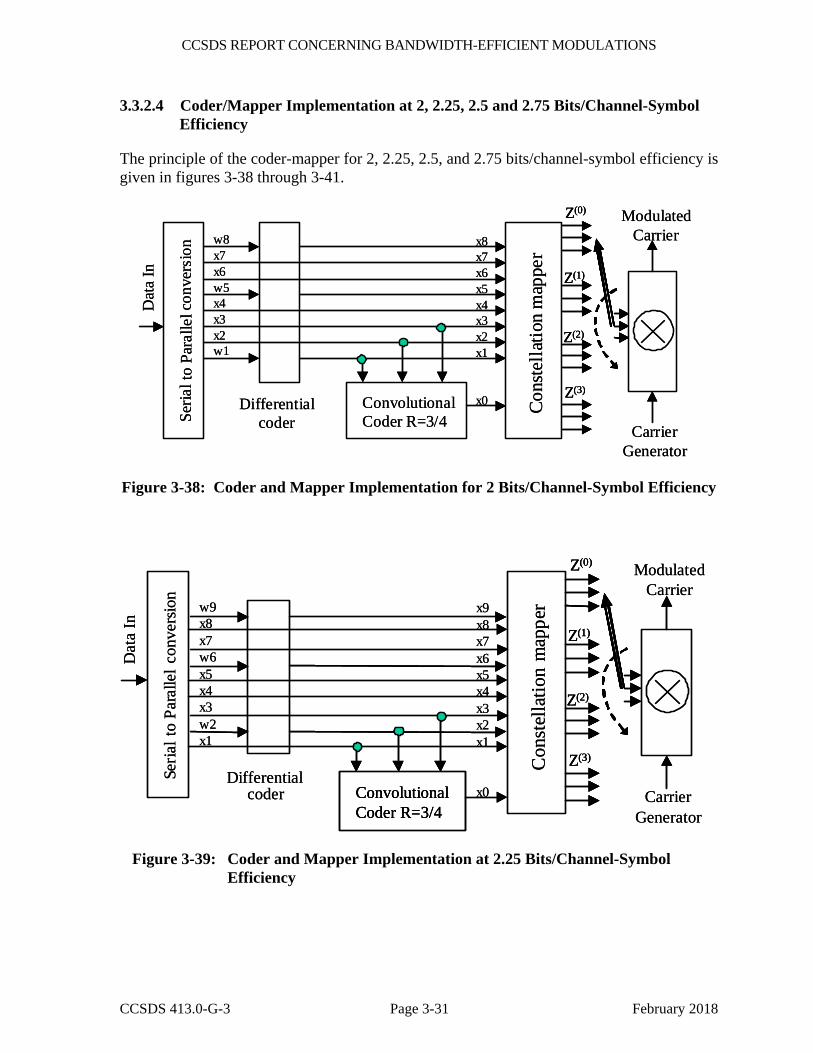
CCSDS REPORT CONCERNING BANDWIDTH-EFFICIENT MODULATIONS
CCSDS 413.0-G-3 Page 3-31 February 2018
3.3.2.4 Coder/Mapper Implementation at 2, 2.25, 2.5 and 2.75 Bits/Channel-Symbol Efficiency
The principle of the coder-mapper for 2, 2.25, 2.5, and 2.75 bits/channel-symbol efficiency is given in figures 3-38 through 3-41.
Seria
l to
Para
llel c
onve
rsio
n
Differentialcoder
Cons
tella
tion
map
per
w8x7x6w5x4x3x2w1
ConvolutionalCoder R=3/4
x8x7x6x5x4x3x2x1
x0
CarrierGenerator
ModulatedCarrier
Dat
a In
Z(0)
Z(1)
Z(2)
Z(3)
Seria
l to
Para
llel c
onve
rsio
n
Differentialcoder
Cons
tella
tion
map
per
w8x7x6w5x4x3x2w1
ConvolutionalCoder R=3/4
x8x7x6x5x4x3x2x1
x0
CarrierGenerator
ModulatedCarrier
Dat
a In
Z(0)
Z(1)
Z(2)
Z(3)
Z(0)
Z(1)
Z(2)
Z(3)
Figure 3-38: Coder and Mapper Implementation for 2 Bits/Channel-Symbol Efficiency
Seria
l to
Para
llel c
onve
rsio
n
Differentialcoder
Con
stel
latio
n m
appe
rw9x8x7w6x5x4x3w2x1
ConvolutionalCoder R=3/4
x9x8x7x6x5x4x3x2x1
x0 CarrierGenerator
ModulatedCarrier
Dat
a In
Z(0)
Z(1)
Z(2)
Z(3)
Seria
l to
Para
llel c
onve
rsio
n
Differentialcoder
Con
stel
latio
n m
appe
rw9x8x7w6x5x4x3w2x1
ConvolutionalCoder R=3/4ConvolutionalCoder R=3/4
x9x8x7x6x5x4x3x2x1
x0 CarrierGenerator
ModulatedCarrier
Dat
a In
Z(0)
Z(1)
Z(2)
Z(3)
Z(0)
Z(1)
Z(2)
Z(3)
Figure 3-39: Coder and Mapper Implementation at 2.25 Bits/Channel-Symbol Efficiency
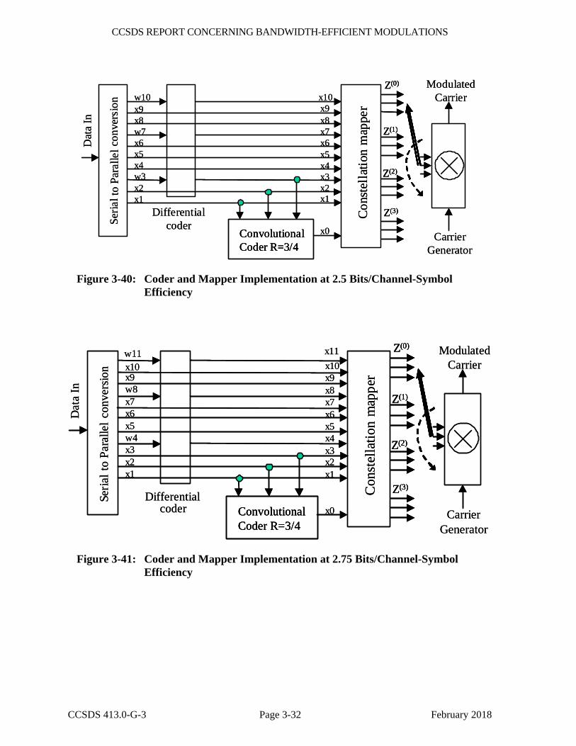
CCSDS REPORT CONCERNING BANDWIDTH-EFFICIENT MODULATIONS
CCSDS 413.0-G-3 Page 3-32 February 2018
Seria
l to
Para
llel c
onve
rsio
n
Differentialcoder
Cons
tella
tion
map
per
w10x9x8w7x6x5x4w3x2x1
ConvolutionalCoder R=3/4
x10x9x8x7x6x5x4x3x2x1
x0 CarrierGenerator
ModulatedCarrier
Dat
a In
Z(0)
Z(1)
Z(2)
Z(3)
Seria
l to
Para
llel c
onve
rsio
n
Differentialcoder
Cons
tella
tion
map
per
w10x9x8w7x6x5x4w3x2x1
ConvolutionalCoder R=3/4ConvolutionalCoder R=3/4
x10x9x8x7x6x5x4x3x2x1
x0 CarrierGenerator
ModulatedCarrier
Dat
a In
Z(0)
Z(1)
Z(2)
Z(3)
Z(0)
Z(1)
Z(2)
Z(3)
Figure 3-40: Coder and Mapper Implementation at 2.5 Bits/Channel-Symbol Efficiency
Seria
l to
Para
llel c
onve
rsio
n
Differentialcoder
Con
stel
latio
n m
appe
rx10x9w8x7x6x5w4x3x2x1
ConvolutionalCoder R=3/4
x10x9x8x7x6x5x4x3x2x1
x0 CarrierGenerator
ModulatedCarrier
Dat
a In
w11 x11 Z(0)
Z(1)
Z(2)
Z(3)
Seria
l to
Para
llel c
onve
rsio
n
Differentialcoder
Con
stel
latio
n m
appe
rx10x9w8x7x6x5w4x3x2x1
ConvolutionalCoder R=3/4ConvolutionalCoder R=3/4
x10x9x8x7x6x5x4x3x2x1
x0 CarrierGenerator
ModulatedCarrier
Dat
a In
w11 x11 Z(0)
Z(1)
Z(2)
Z(3)
Z(0)
Z(1)
Z(2)
Z(3)
Figure 3-41: Coder and Mapper Implementation at 2.75 Bits/Channel-Symbol Efficiency

CCSDS REPORT CONCERNING BANDWIDTH-EFFICIENT MODULATIONS
CCSDS 413.0-G-3 Page 3-33 February 2018
3.3.3 4D-8PSK-TCM PHASE NOISE RECOMMENDATION
It is recommended that the phase noise for all the oscillators of the 4D-8PSK-TCM communication chain be limited according to the mask given in figure 3-42 for channel symbol rates from 1 Ms/s up to 100 Ms/s. The figure shows the double-sided phase noise mask 2L(f) in dBc/Hz versus frequency in Hz.
‐130
‐120
‐110
‐100
‐90
‐80
‐70
‐60
‐50
‐40
‐30
‐20
1.00E+01 1.00E+02 1.00E+03 1.00E+04 1.00E+05 1.00E+06 1.00E+07 1.00E+08 1.00E+09
2L(f) in
dBc/H
z
f in Hz
Phase noise mask
Figure 3-42: 4D-8PSK-TCM Phase Noise Mask Recommendation
3.3.4 CHANNEL FILTERING
Channel filtering is to be obtained by one of the following methods:
– Square root raised cosine (SRRC) baseband shaping filter located prior to the modulator, with a channel roll-off factor α of 0.35 or 0.5. This waveform shaping is used in conjunction with a linear modulator and power amplifier.
– Post-amplifier shaping using a filter located at the output of a non-linear power amplifier. In this case, post-amplifier filtering of the NRZ 8-PSK signal is used in conjunction with a non-linear phase modulator or power amplifier.
In both cases, the pre-detection filter (matched filter) in the receiver shall be a SRRC filter with a roll-off factor α of 0.35 or 0.5.
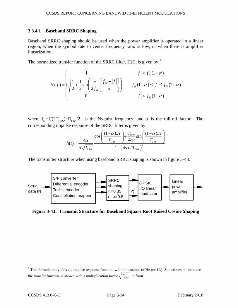
CCSDS REPORT CONCERNING BANDWIDTH-EFFICIENT MODULATIONS
CCSDS 413.0-G-3 Page 3-34 February 2018
3.3.4.1 Baseband SRRC Shaping
Baseband SRRC shaping should be used when the power amplifier is operated in a linear region, when the symbol rate to center frequency ratio is low, or when there is amplifier linearization.
The normalized transfer function of the SRRC filter, H(f), is given by:7
⎪⎪
⎩
⎪⎪
⎨
⎧
+>
+≤≤−⎟⎟⎠
⎞⎜⎜⎝
⎛⎥⎦
⎤⎢⎣
⎡ −+
−<
=
)1(0
)1()1(2
sin21
21
)1(1
)(
α
ααα
π
α
N
NNN
N
N
ff
fffff
f
ff
fH
where fN=1/(2TChS)=RChS/2 is the Nyquist frequency, and α is the roll-off factor. The corresponding impulse response of the SRRC filter is given by:
( )2
(1 ) (1 )cos sin44( )
1 4 /
ChS
ChS ChS
ChS ChS
Tt tT t T
h tT t T
α π α παα
π α
⎛ ⎞ ⎛ ⎞+ −+⎜ ⎟ ⎜ ⎟⎝ ⎠ ⎝ ⎠=
−
The transmitter structure when using baseband SRRC shaping is shown in figure 3-43.
I
Q
S/P converterDifferential encoderTrellis encoderConstellation mapper
SRRCshaping
=0.35or =0.5
8-PSKI/Q linearmodulator
Linearpoweramplifier
Serialdata IN
αα
Figure 3-43: Transmit Structure for Baseband Square Root Raised Cosine Shaping
7 This formulation yields an impulse response function with dimensions of Hz (or 1/s). Sometimes in literature, the transfer function is shown with a multiplication factor ChST in front..
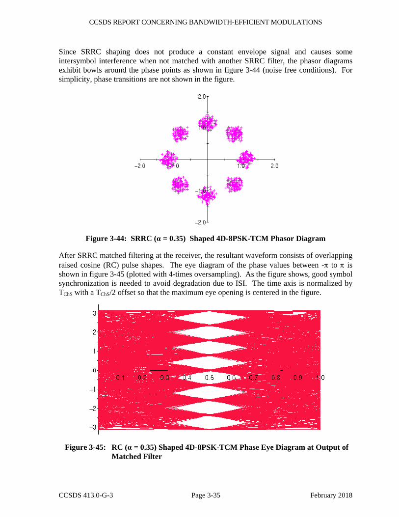
CCSDS REPORT CONCERNING BANDWIDTH-EFFICIENT MODULATIONS
CCSDS 413.0-G-3 Page 3-35 February 2018
Since SRRC shaping does not produce a constant envelope signal and causes some intersymbol interference when not matched with another SRRC filter, the phasor diagrams exhibit bowls around the phase points as shown in figure 3-44 (noise free conditions). For simplicity, phase transitions are not shown in the figure.
Figure 3-44: SRRC (α = 0.35) Shaped 4D-8PSK-TCM Phasor Diagram
After SRRC matched filtering at the receiver, the resultant waveform consists of overlapping raised cosine (RC) pulse shapes. The eye diagram of the phase values between -π to π is shown in figure 3-45 (plotted with 4-times oversampling). As the figure shows, good symbol synchronization is needed to avoid degradation due to ISI. The time axis is normalized by TChS with a TChS/2 offset so that the maximum eye opening is centered in the figure.
Figure 3-45: RC (α = 0.35) Shaped 4D-8PSK-TCM Phase Eye Diagram at Output of Matched Filter
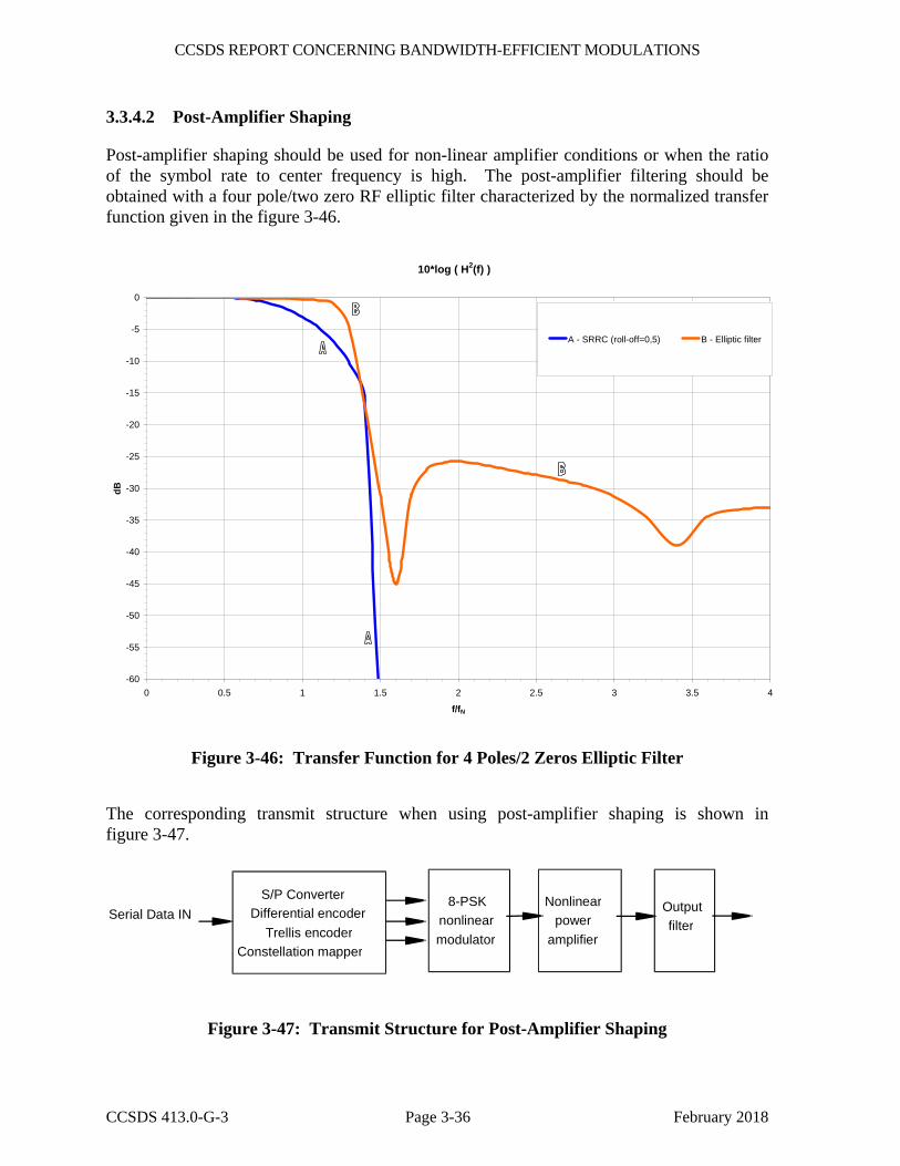
CCSDS REPORT CONCERNING BANDWIDTH-EFFICIENT MODULATIONS
CCSDS 413.0-G-3 Page 3-36 February 2018
3.3.4.2 Post-Amplifier Shaping
Post-amplifier shaping should be used for non-linear amplifier conditions or when the ratio of the symbol rate to center frequency is high. The post-amplifier filtering should be obtained with a four pole/two zero RF elliptic filter characterized by the normalized transfer function given in the figure 3-46.
10*log ( H2(f) )
-60
-55
-50
-45
-40
-35
-30
-25
-20
-15
-10
-5
0
0 0.5 1 1.5 2 2.5 3 3.5 4
f/fN
dB
A - SRRC (roll-off=0,5) B - Elliptic filter
Figure 3-46: Transfer Function for 4 Poles/2 Zeros Elliptic Filter
The corresponding transmit structure when using post-amplifier shaping is shown in figure 3-47.
S/P Converter Differential encoder
Trellis encoder Constellation mapper
8-PSK nonlinear modulator
Nonlinear power
amplifier
Output filter
Serial Data IN
Figure 3-47: Transmit Structure for Post-Amplifier Shaping
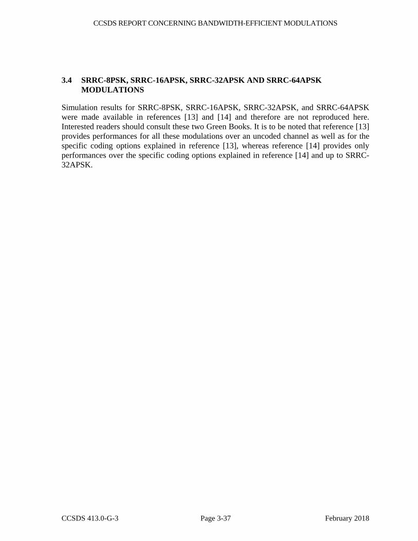
CCSDS REPORT CONCERNING BANDWIDTH-EFFICIENT MODULATIONS
CCSDS 413.0-G-3 Page 3-37 February 2018
3.4 SRRC-8PSK, SRRC-16APSK, SRRC-32APSK AND SRRC-64APSK MODULATIONS
Simulation results for SRRC-8PSK, SRRC-16APSK, SRRC-32APSK, and SRRC-64APSK were made available in references [13] and [14] and therefore are not reproduced here. Interested readers should consult these two Green Books. It is to be noted that reference [13] provides performances for all these modulations over an uncoded channel as well as for the specific coding options explained in reference [13], whereas reference [14] provides only performances over the specific coding options explained in reference [14] and up to SRRC-32APSK.
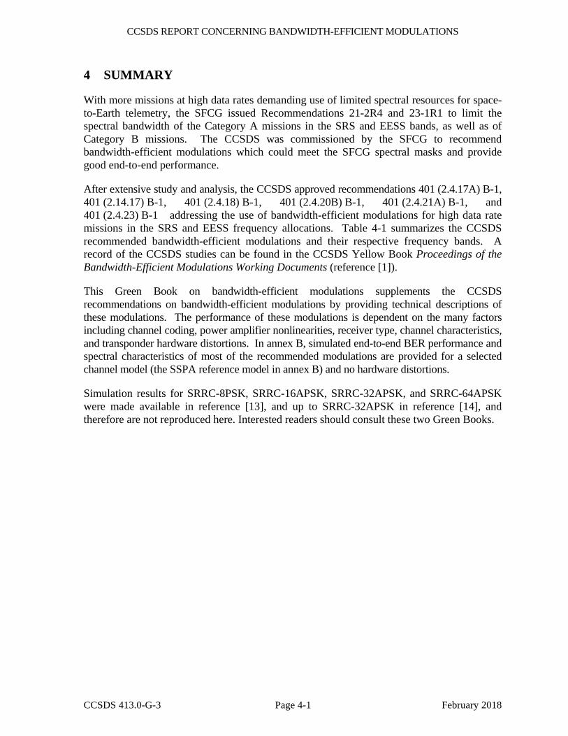
CCSDS REPORT CONCERNING BANDWIDTH-EFFICIENT MODULATIONS
CCSDS 413.0-G-3 Page 4-1 February 2018
4 SUMMARY
With more missions at high data rates demanding use of limited spectral resources for space-to-Earth telemetry, the SFCG issued Recommendations 21-2R4 and 23-1R1 to limit the spectral bandwidth of the Category A missions in the SRS and EESS bands, as well as of Category B missions. The CCSDS was commissioned by the SFCG to recommend bandwidth-efficient modulations which could meet the SFCG spectral masks and provide good end-to-end performance.
After extensive study and analysis, the CCSDS approved recommendations 401 (2.4.17A) B-1, 401 (2.14.17) B-1, 401 (2.4.18) B-1, 401 (2.4.20B) B-1, 401 (2.4.21A) B-1, and 401 (2.4.23) B-1 addressing the use of bandwidth-efficient modulations for high data rate missions in the SRS and EESS frequency allocations. Table 4-1 summarizes the CCSDS recommended bandwidth-efficient modulations and their respective frequency bands. A record of the CCSDS studies can be found in the CCSDS Yellow Book Proceedings of the Bandwidth-Efficient Modulations Working Documents (reference [1]).
This Green Book on bandwidth-efficient modulations supplements the CCSDS recommendations on bandwidth-efficient modulations by providing technical descriptions of these modulations. The performance of these modulations is dependent on the many factors including channel coding, power amplifier nonlinearities, receiver type, channel characteristics, and transponder hardware distortions. In annex B, simulated end-to-end BER performance and spectral characteristics of most of the recommended modulations are provided for a selected channel model (the SSPA reference model in annex B) and no hardware distortions.
Simulation results for SRRC-8PSK, SRRC-16APSK, SRRC-32APSK, and SRRC-64APSK were made available in reference [13], and up to SRRC-32APSK in reference [14], and therefore are not reproduced here. Interested readers should consult these two Green Books.

CCSDS REPORT CONCERNING BANDWIDTH-EFFICIENT MODULATIONS
CCSDS 413.0-G-3 Page 4-2 February 2018
Table 4-1: CCSDS Recommendations on Bandwidth-Efficient Modulations
Frequency Band Applicable CCSDS Recommendation(s) Recommended Modulations
2200-2290 MHz 8450-8500 MHz
401 (2.4.17A) B-1 – GMSK BTs=0.25 with precoding – Filtered OQPSK
2290-2300 MHz 8400-8450 MHz
401 (2.4.17B) B-1 – GMSK BTs=0.5 with precoding
8025-8400 MHz 401 (2.4.18) B-1 – 4D-8PSK-TCM – SRRC-QPSK, SRRC-OQPSK, SRRC-
8PSK, SRRC-16APSK, SRRC-32APSK and SRRC-64APSK
– Filtered OQPSK 31800-32300 MHz 401 (2.4.20B) B-1 – GMSK BTs=0.5 with precoding 25500-27000 MHz 401 (2.4.21A) B-1 – GMSK BTs=0.25 with precoding
– Filtered OQPSK 25500-27000 MHz 401 (2.4.23) B-1 – SRRC-QPSK, SRRC-OQPSK, SRRC-
8PSK, SRRC-16APSK, SRRC-32APSK and SRRC-64APSK

CCSDS REPORT CONCERNING BANDWIDTH-EFFICIENT MODULATIONS
CCSDS 413.0-G-3 Page A-1 February 2018
ANNEX A
GLOSSARY
ACM Adaptive Coding and Modulation
AM/AM Amplitude-dependent amplitude distortion
AM/PM Amplitude-dependent phase distortion
AGC Automatic Gain Control
BER Bit Error Rate
BPSK Binary Phase Shift Keying
Category A mission Missions whose altitude above Earth is less than 2×10⁶ km
Category B mission Missions whose altitude above Earth is greater than 2×10⁶ km
CCSDS Consultative Committee on Space Data Systems
CPM Continuous Phase Modulation
dB Decibel
Eb/No Energy per bit to Noise spectral density ratio
Es/No Energy per symbol to Noise spectral density ratio
EESS Earth Exploration Satellite Service
FSK Frequency Shift Keying
GHz Gigahertz
GMSK Gaussian Minimum Shift Keying
I&D Integrate-and-Dump
ISI Inter-Symbol Interference
ITU International Telecommunication Union
LPF Low Pass Filter
Ms/s Mega Symbols Per Second
CCSDS REPORT CONCERNING BANDWIDTH-EFFICIENT MODULATIONS
CCSDS 413.0-G-3 Page A-2 February 2018
NRZ Non-Return to Zero
OBO Output Back-off
OQPSK Offset Quadrature Phase Shift Keying
OQPSK I/Q I/Q Modulated Offset Quadrature Phase Shift Keying
OQPSK/PM Phase Modulated Offset Quadrature Phase Shift Keying
OSC Oscillator
PM Phase Modulated
PSD Power Spectral Density
Rs Coded symbol rate at input to modulator
Rb Information bit rate
RChS Channel symbol rate
RF Radio Frequency
SFCG Space Frequency Coordination Group
SRRC Square Root Raised Cosine
SRS Space Research Service
SSPA Solid State Power Amplifier
Ts Coded symbol period at input to modulator
Tb Bit period
TChS Channel symbol period
TCM Trellis Coded Modulation
TWTA Traveling Wave Tube Amplifier
VCM Variable Coding and Modulation
VCO Voltage Controlled Oscillator
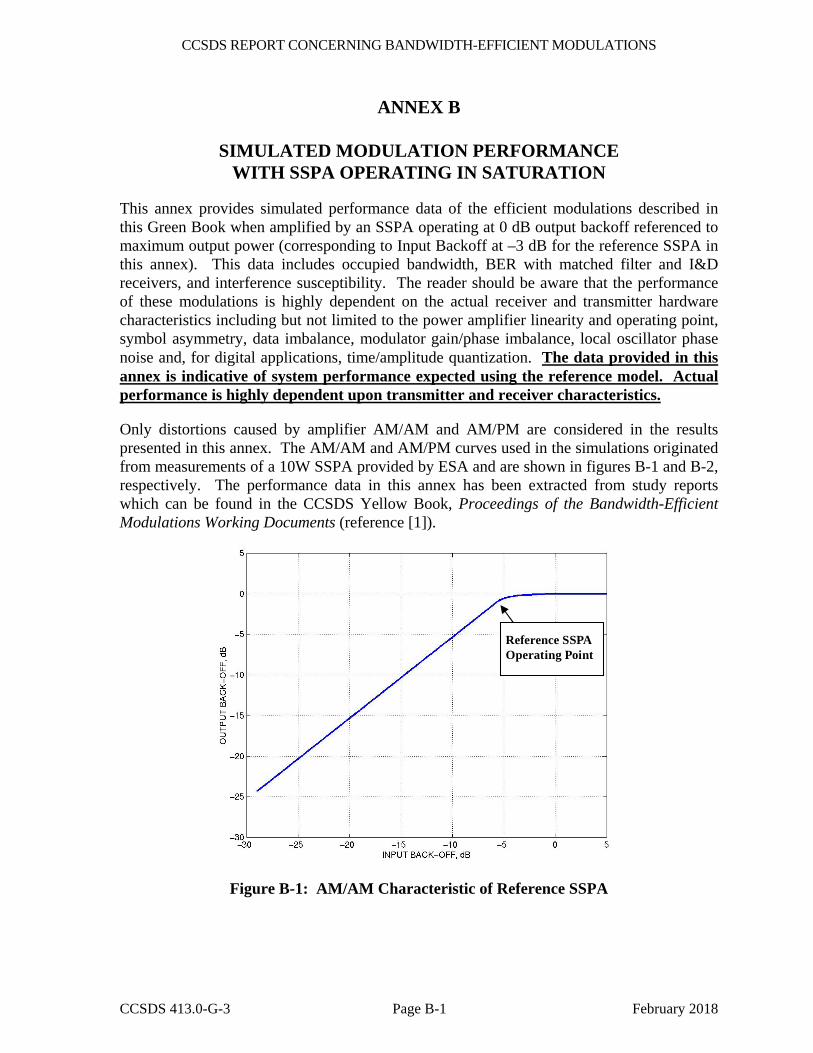
CCSDS REPORT CONCERNING BANDWIDTH-EFFICIENT MODULATIONS
CCSDS 413.0-G-3 Page B-1 February 2018
ANNEX B
SIMULATED MODULATION PERFORMANCE WITH SSPA OPERATING IN SATURATION
This annex provides simulated performance data of the efficient modulations described in this Green Book when amplified by an SSPA operating at 0 dB output backoff referenced to maximum output power (corresponding to Input Backoff at –3 dB for the reference SSPA in this annex). This data includes occupied bandwidth, BER with matched filter and I&D receivers, and interference susceptibility. The reader should be aware that the performance of these modulations is highly dependent on the actual receiver and transmitter hardware characteristics including but not limited to the power amplifier linearity and operating point, symbol asymmetry, data imbalance, modulator gain/phase imbalance, local oscillator phase noise and, for digital applications, time/amplitude quantization. The data provided in this annex is indicative of system performance expected using the reference model. Actual performance is highly dependent upon transmitter and receiver characteristics.
Only distortions caused by amplifier AM/AM and AM/PM are considered in the results presented in this annex. The AM/AM and AM/PM curves used in the simulations originated from measurements of a 10W SSPA provided by ESA and are shown in figures B-1 and B-2, respectively. The performance data in this annex has been extracted from study reports which can be found in the CCSDS Yellow Book, Proceedings of the Bandwidth-Efficient Modulations Working Documents (reference [1]).
Reference SSPAOperating Point
Figure B-1: AM/AM Characteristic of Reference SSPA
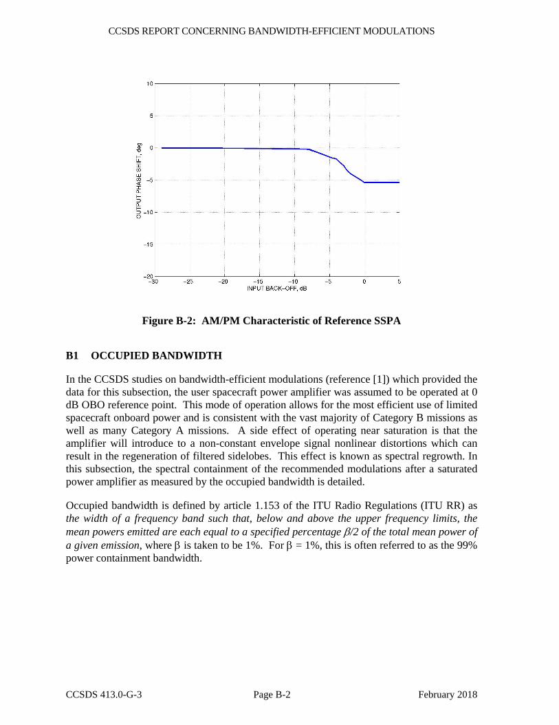
CCSDS REPORT CONCERNING BANDWIDTH-EFFICIENT MODULATIONS
CCSDS 413.0-G-3 Page B-2 February 2018
Figure B-2: AM/PM Characteristic of Reference SSPA
B1 OCCUPIED BANDWIDTH
In the CCSDS studies on bandwidth-efficient modulations (reference [1]) which provided the data for this subsection, the user spacecraft power amplifier was assumed to be operated at 0 dB OBO reference point. This mode of operation allows for the most efficient use of limited spacecraft onboard power and is consistent with the vast majority of Category B missions as well as many Category A missions. A side effect of operating near saturation is that the amplifier will introduce to a non-constant envelope signal nonlinear distortions which can result in the regeneration of filtered sidelobes. This effect is known as spectral regrowth. In this subsection, the spectral containment of the recommended modulations after a saturated power amplifier as measured by the occupied bandwidth is detailed.
Occupied bandwidth is defined by article 1.153 of the ITU Radio Regulations (ITU RR) as the width of a frequency band such that, below and above the upper frequency limits, the mean powers emitted are each equal to a specified percentage β/2 of the total mean power of a given emission, where β is taken to be 1%. For β = 1%, this is often referred to as the 99% power containment bandwidth.

CCSDS REPORT CONCERNING BANDWIDTH-EFFICIENT MODULATIONS
CCSDS 413.0-G-3 Page B-3 February 2018
Table B-1 shows the simulated occupied bandwidths normalized to the symbol rate8 at the input to the modulator of selected bandwidth-efficient modulations recommended for Category A space-to-Earth links at the output of a saturated SSPA. In addition, the normalized –60 dB bandwidths9 are given. Table B-2 shows the occupied bandwidths for Category B recommended efficient modulations.
Table B-1: Occupied Bandwidth of Category A Recommended Efficient Modulations after Spectral Regrowth Due to Saturated SSPA
Modulation Type Two Sided -60 dB
Bandwidth 9 Occupied BandwidthUnfiltered BPSK10 635 Rs 20.56 Rs Baseband Filtered OQPSK/PM
Butterworth 6th order BTs=0.5 SRRC (α=0.5) Bessel 6th order BTs=0.5
2.70 Rs 2.68 Rs 3.69 Rs
0.88 Rs 0.88 Rs 0.93 Rs
Baseband Filtered OQPSK I/Q Butterworth 6th order BTs=0.5 SRRC α=0.5 Bessel 6th order BTs=0.5
4.06 Rs 4.24 Rs 4.95 Rs
0.86 Rs 0.88 Rs 1.34 Rs
Precoded GMSK BTs = 0.25 2.14 Rs 0.86 Rs
Table B-2: Occupied Bandwidth of Category B Recommended Efficient Modulations after Spectral Regrowth Due to Saturated SSPA
Modulation Type -60 dB Bandwidth Occupied BandwidthPrecoded GMSK BTs=0.5 3.02 Rs 1.03 Rs
B2 SIMULATED END-TO-END BER PERFORMANCES
B2.1 UNCODED BIT ERROR RATE (BER) PERFORMANCE IN A NON-LINEAR CHANNEL
As a general matter, all of the bandwidth-efficient modulation techniques included in these recommendations provide acceptable BER performance for use in space data systems. However, for each of these modulations, the precise BER performance of any given system is dependent upon the detection algorithm used in the receiver. Accordingly, a meaningful characterization of the BER performance of each modulation type must include some insight into the performance of the modulation type with the receiver types likely to be used. 8 See 2.4 for bit/symbol terminology definitions used in this Green Book. 9 The –60 dB bandwidth is defined here as the frequency band such that, below the lower frequency limit and above the upper frequency limit, the continuous power spectral density does not exceed –60 dB/Hz below the peak PSD over any 1 Hz bandwidth. This level is chosen to coincide with the floor of the SFCG 21-2 spectral emissions mask. 10 For reference purposes only; not part of bandwidth-efficient modulation recommendation.
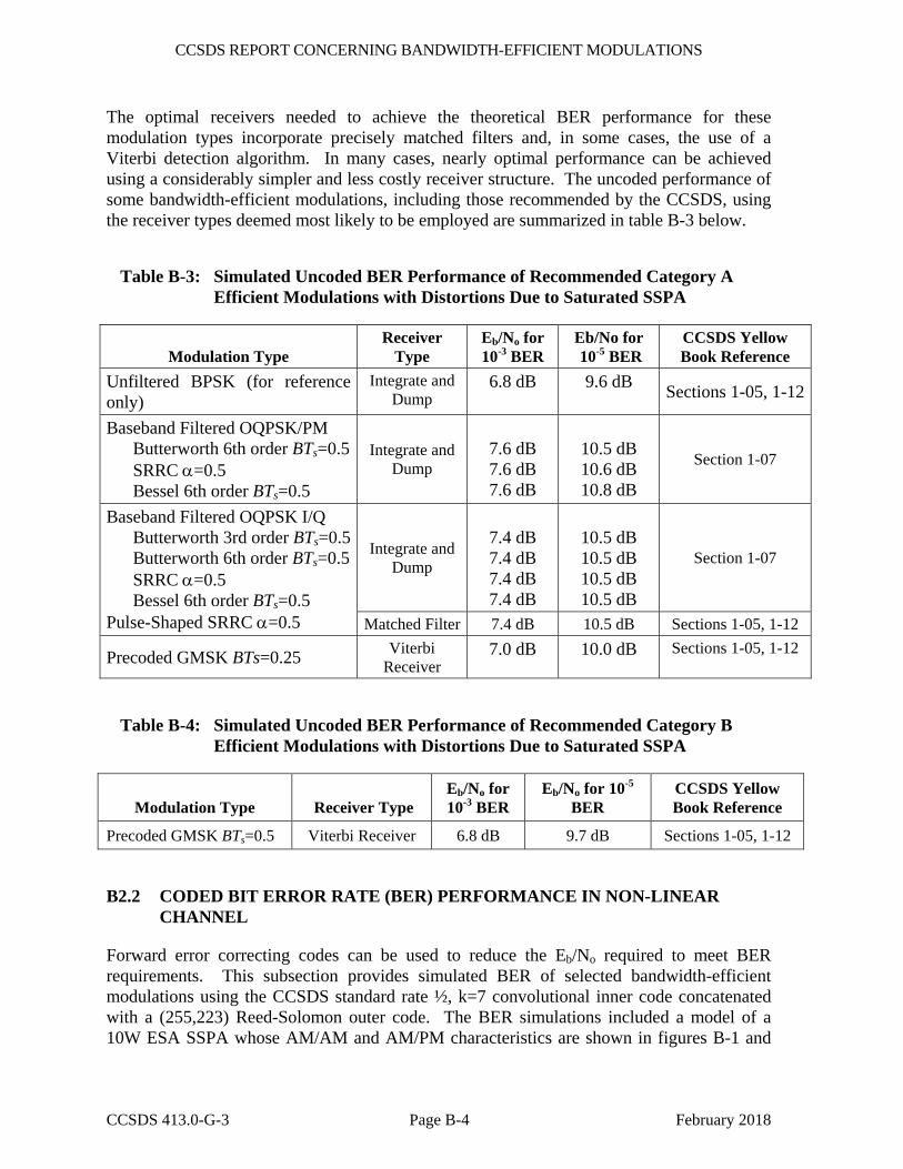
CCSDS REPORT CONCERNING BANDWIDTH-EFFICIENT MODULATIONS
CCSDS 413.0-G-3 Page B-4 February 2018
The optimal receivers needed to achieve the theoretical BER performance for these modulation types incorporate precisely matched filters and, in some cases, the use of a Viterbi detection algorithm. In many cases, nearly optimal performance can be achieved using a considerably simpler and less costly receiver structure. The uncoded performance of some bandwidth-efficient modulations, including those recommended by the CCSDS, using the receiver types deemed most likely to be employed are summarized in table B-3 below.
Table B-3: Simulated Uncoded BER Performance of Recommended Category A Efficient Modulations with Distortions Due to Saturated SSPA
Modulation Type Receiver
Type Eb/No for 10-3 BER
Eb/No for 10-5 BER
CCSDS Yellow Book Reference
Unfiltered BPSK (for reference only)
Integrate and Dump
6.8 dB 9.6 dB Sections 1-05, 1-12
Baseband Filtered OQPSK/PM Butterworth 6th order BTs=0.5 SRRC α=0.5 Bessel 6th order BTs=0.5
Integrate and Dump
7.6 dB 7.6 dB 7.6 dB
10.5 dB 10.6 dB 10.8 dB
Section 1-07
Baseband Filtered OQPSK I/Q Butterworth 3rd order BTs=0.5 Butterworth 6th order BTs=0.5 SRRC α=0.5 Bessel 6th order BTs=0.5
Pulse-Shaped SRRC α=0.5
Integrate and Dump
7.4 dB 7.4 dB 7.4 dB 7.4 dB
10.5 dB 10.5 dB 10.5 dB 10.5 dB
Section 1-07
Matched Filter 7.4 dB 10.5 dB Sections 1-05, 1-12
Precoded GMSK BTs=0.25 Viterbi Receiver
7.0 dB 10.0 dB Sections 1-05, 1-12
Table B-4: Simulated Uncoded BER Performance of Recommended Category B Efficient Modulations with Distortions Due to Saturated SSPA
Modulation Type Receiver Type Eb/No for 10-3 BER
Eb/No for 10-5 BER
CCSDS Yellow Book Reference
Precoded GMSK BTs=0.5 Viterbi Receiver 6.8 dB 9.7 dB Sections 1-05, 1-12
B2.2 CODED BIT ERROR RATE (BER) PERFORMANCE IN NON-LINEAR CHANNEL
Forward error correcting codes can be used to reduce the Eb/No required to meet BER requirements. This subsection provides simulated BER of selected bandwidth-efficient modulations using the CCSDS standard rate ½, k=7 convolutional inner code concatenated with a (255,223) Reed-Solomon outer code. The BER simulations included a model of a 10W ESA SSPA whose AM/AM and AM/PM characteristics are shown in figures B-1 and
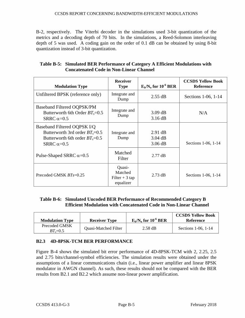
CCSDS REPORT CONCERNING BANDWIDTH-EFFICIENT MODULATIONS
CCSDS 413.0-G-3 Page B-5 February 2018
B-2, respectively. The Viterbi decoder in the simulations used 3-bit quantization of the metrics and a decoding depth of 70 bits. In the simulations, a Reed-Solomon interleaving depth of 5 was used. A coding gain on the order of 0.1 dB can be obtained by using 8-bit quantization instead of 3-bit quantization.
Table B-5: Simulated BER Performance of Category A Efficient Modulations with Concatenated Code in Non-Linear Channel
Modulation Type Receiver
Type Eb/No for 10-6 BER CCSDS Yellow Book
Reference
Unfiltered BPSK (reference only) Integrate and Dump 2.55 dB Sections 1-06, 1-14
Baseband Filtered OQPSK/PM Butterworth 6th Order BTs=0.5 SRRC α=0.5
Integrate and Dump
3.09 dB 3.16 dB
N/A
Baseband Filtered OQPSK I/Q Butterworth 3rd order BTs=0.5 Butterworth 6th order BTs=0.5 SRRC α=0.5
Pulse-Shaped SRRC α=0.5
Integrate and Dump
2.91 dB 3.04 dB 3.06 dB Sections 1-06, 1-14
Matched Filter 2.77 dB
Precoded GMSK BTs=0.25
Quasi-Matched
Filter + 3 tap equalizer
2.73 dB Sections 1-06, 1-14
Table B-6: Simulated Uncoded BER Performance of Recommended Category B Efficient Modulation with Concatenated Code in Non-Linear Channel
Modulation Type Receiver Type Eb/No for 10-6 BERCCSDS Yellow Book
ReferencePrecoded GMSK
BTs=0.5 Quasi-Matched Filter 2.58 dB Sections 1-06, 1-14
B2.3 4D-8PSK-TCM BER PERFORMANCE
Figure B-4 shows the simulated bit error performance of 4D-8PSK-TCM with 2, 2.25, 2.5 and 2.75 bits/channel-symbol efficiencies. The simulation results were obtained under the assumptions of a linear communications chain (i.e., linear power amplifier and linear 8PSK modulator in AWGN channel). As such, these results should not be compared with the BER results from B2.1 and B2.2 which assume non-linear power amplification.
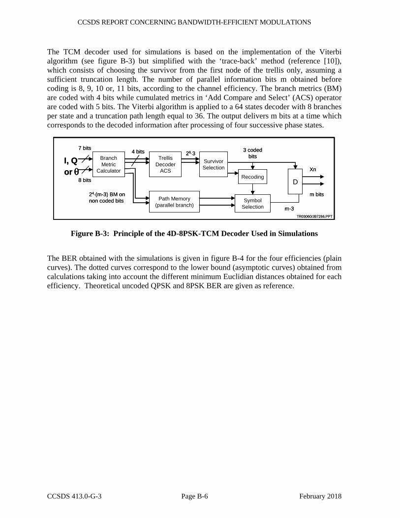
CCSDS REPORT CONCERNING BANDWIDTH-EFFICIENT MODULATIONS
CCSDS 413.0-G-3 Page B-6 February 2018
The TCM decoder used for simulations is based on the implementation of the Viterbi algorithm (see figure B-3) but simplified with the ‘trace-back’ method (reference [10]), which consists of choosing the survivor from the first node of the trellis only, assuming a sufficient truncation length. The number of parallel information bits m obtained before coding is 8, 9, 10 or, 11 bits, according to the channel efficiency. The branch metrics (BM) are coded with 4 bits while cumulated metrics in ‘Add Compare and Select’ (ACS) operator are coded with 5 bits. The Viterbi algorithm is applied to a 64 states decoder with 8 branches per state and a truncation path length equal to 36. The output delivers m bits at a time which corresponds to the decoded information after processing of four successive phase states.
I, Q or θ
m-3
Xn
7 bits4 bits
8 bits
Branch Metric
Calculator
24⋅(m-3) BM on non coded bits
Trellis Decoder
ACS
Path Memory (parallel branch)
Survivor Selection
Recoding
SymbolSelection
D
m bits
3 coded bits26⋅3
TR03060/JB7266.PPT
I, Q or θ
m-3
Xn
7 bits4 bits
8 bits
Branch Metric
Calculator
24⋅(m-3) BM on non coded bits
Trellis Decoder
ACS
Path Memory (parallel branch)
Survivor Selection
Recoding
SymbolSelection
D
m bits
3 coded bits26⋅3
TR03060/JB7266.PPT
Figure B-3: Principle of the 4D-8PSK-TCM Decoder Used in Simulations
The BER obtained with the simulations is given in figure B-4 for the four efficiencies (plain curves). The dotted curves correspond to the lower bound (asymptotic curves) obtained from calculations taking into account the different minimum Euclidian distances obtained for each efficiency. Theoretical uncoded QPSK and 8PSK BER are given as reference.
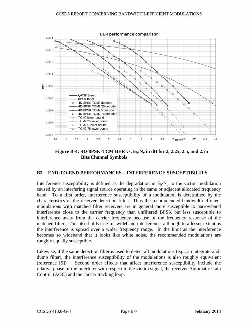
CCSDS REPORT CONCERNING BANDWIDTH-EFFICIENT MODULATIONS
CCSDS 413.0-G-3 Page B-7 February 2018
BER performance comparison
1.0E-9
1.0E-8
1.0E-7
1.0E-6
1.0E-5
1.0E-4
1.0E-3
1.0E-2
1.0E-1
3.5 4 4.5 5 5.5 6 6.5 7 7.5 8 8.5 9 9.5 10 10.5 11Eb/No
BER
QPSK theor.8PSK theor.4D-8PSK TCM2 decoder4D-8PSK TCM2.25 decoder4D-8PSK TCM2.5 decoder4D-8PSK TCM2.75 decoderTCM2 lower boundTCM2.25 lower boundTCM2.5 lower boundTCM2.75 lower bound
Figure B-4: 4D-8PSK-TCM BER vs. Eb/No in dB for 2, 2.25, 2.5, and 2.75 Bits/Channel Symbols
B3 END-TO-END PERFORMANCES – INTERFERENCE SUSCEPTIBILITY
Interference susceptibility is defined as the degradation in Eb/No to the victim modulation caused by an interfering signal source operating in the same or adjacent allocated frequency band. To a first order, interference susceptibility of a modulation is determined by the characteristics of the receiver detection filter. Thus the recommended bandwidth-efficient modulations with matched filter receivers are in general more susceptible to narrowband interference close to the carrier frequency than unfiltered BPSK but less susceptible to interference away from the carrier frequency because of the frequency response of the matched filter. This also holds true for wideband interference, although to a lesser extent as the interference is spread over a wider frequency range. In the limit as the interference becomes so wideband that it looks like white noise, the recommended modulations are roughly equally susceptible.
Likewise, if the same detection filter is used to detect all modulations (e.g., an integrate-and-dump filter), the interference susceptibility of the modulations is also roughly equivalent (reference [5]). Second order effects that affect interference susceptibility include the relative phase of the interferer with respect to the victim signal, the receiver Automatic Gain Control (AGC) and the carrier tracking loop.
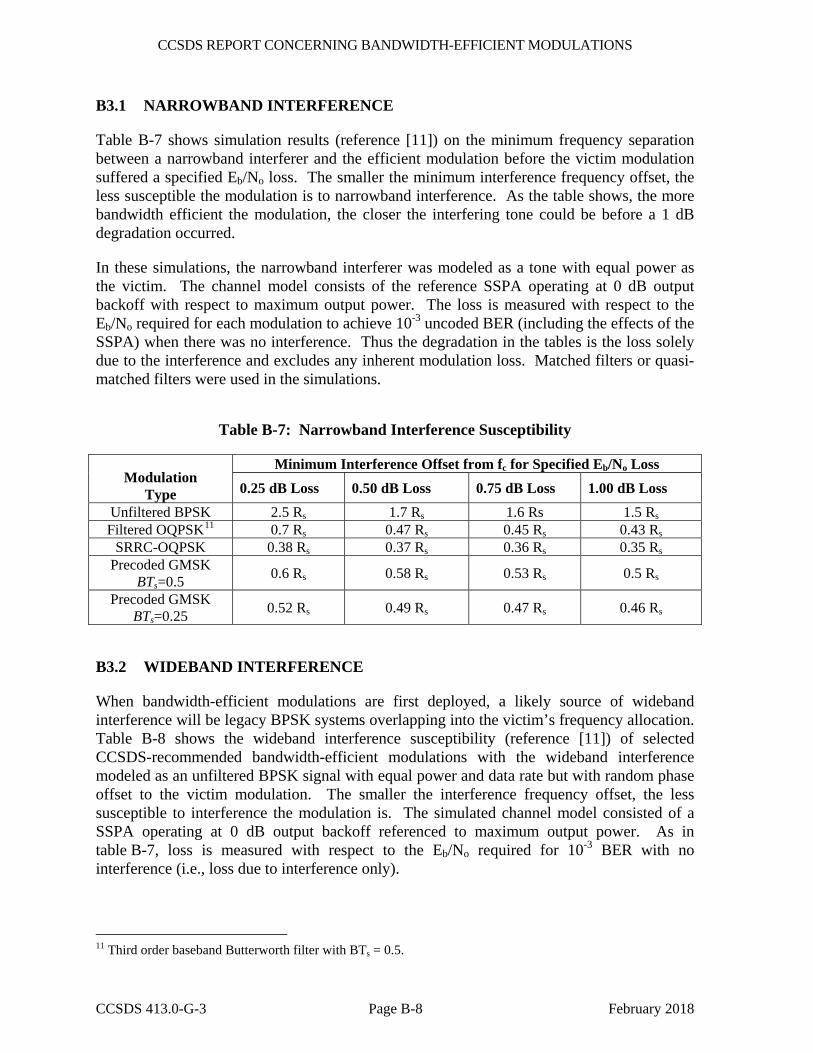
CCSDS REPORT CONCERNING BANDWIDTH-EFFICIENT MODULATIONS
CCSDS 413.0-G-3 Page B-8 February 2018
B3.1 NARROWBAND INTERFERENCE
Table B-7 shows simulation results (reference [11]) on the minimum frequency separation between a narrowband interferer and the efficient modulation before the victim modulation suffered a specified Eb/No loss. The smaller the minimum interference frequency offset, the less susceptible the modulation is to narrowband interference. As the table shows, the more bandwidth efficient the modulation, the closer the interfering tone could be before a 1 dB degradation occurred.
In these simulations, the narrowband interferer was modeled as a tone with equal power as the victim. The channel model consists of the reference SSPA operating at 0 dB output backoff with respect to maximum output power. The loss is measured with respect to the Eb/No required for each modulation to achieve 10-3 uncoded BER (including the effects of the SSPA) when there was no interference. Thus the degradation in the tables is the loss solely due to the interference and excludes any inherent modulation loss. Matched filters or quasi-matched filters were used in the simulations.
Table B-7: Narrowband Interference Susceptibility
Modulation Type
Minimum Interference Offset from fc for Specified Eb/No Loss
0.25 dB Loss 0.50 dB Loss 0.75 dB Loss 1.00 dB Loss Unfiltered BPSK 2.5 Rs 1.7 Rs 1.6 Rs 1.5 Rs Filtered OQPSK11 0.7 Rs 0.47 Rs 0.45 Rs 0.43 Rs
SRRC-OQPSK 0.38 Rs 0.37 Rs 0.36 Rs 0.35 Rs Precoded GMSK
BTs=0.5 0.6 Rs 0.58 Rs 0.53 Rs 0.5 Rs
Precoded GMSK BTs=0.25 0.52 Rs 0.49 Rs 0.47 Rs 0.46 Rs
B3.2 WIDEBAND INTERFERENCE
When bandwidth-efficient modulations are first deployed, a likely source of wideband interference will be legacy BPSK systems overlapping into the victim’s frequency allocation. Table B-8 shows the wideband interference susceptibility (reference [11]) of selected CCSDS-recommended bandwidth-efficient modulations with the wideband interference modeled as an unfiltered BPSK signal with equal power and data rate but with random phase offset to the victim modulation. The smaller the interference frequency offset, the less susceptible to interference the modulation is. The simulated channel model consisted of a SSPA operating at 0 dB output backoff referenced to maximum output power. As in table B-7, loss is measured with respect to the Eb/No required for 10-3 BER with no interference (i.e., loss due to interference only).
11 Third order baseband Butterworth filter with BTs = 0.5.

CCSDS REPORT CONCERNING BANDWIDTH-EFFICIENT MODULATIONS
CCSDS 413.0-G-3 Page B-9 February 2018
Table B-8: Wideband Interference Susceptibility
Modulation
Type
Minimum Interference Offset from fc for Specified Eb/No Loss
0.25 dB Loss 0.50 dB Loss 0.75 dB Loss 1.00 dB Loss
Unfiltered BPSK > 3 Rs 2.5 Rs 2.4 Rs 1.8 Rs Filtered OQPSK12 1.05 Rs 0.96 Rs 0.88 Rs 0.8 Rs
SRRC-OQPSK 1.3 Rs 1.0 Rs 0.93 Rs 0.9 Rs Precoded GMSK
BTs=0.5 1.3 Rs 1.18 Rs 1.12 Rs 1.09 Rs
Precoded GMSK BTs=0.25 1.06 Rs 0.98 Rs 0.90 Rs 0.85 Rs
B3.3 CO-CHANNEL INTERFERENCE
Table B-9 shows the interference susceptibility of the recommended modulations assuming that the interferer is of the same modulation type as the victim (reference [12]). Here, the interference susceptibility is measured by the required victim-power-to-interferer-power ratio, P_S/P_I, that caused a degradation of 1 dB with respect to ideal BPSK in AWGN at BER equal to 10-1, 10-2, and 10-3. The higher the value of P_S/P_I, the more susceptible to interference the modulation is. Table B-9 shows the values for P_S/P_I with the co-channel interferer centered at the victim carrier frequency, and at a frequency offset a quarter times the coded symbol rate at the input to the modulator. The simulated channel model consisted of the reference SSPA operating at 0 dB output backoff with respect to maximum output power. In the results in table B-9, the interferer is assumed to have a worst-case phase and timing offset that causes the largest amount of degradation.
Table B-9: Co-Channel Interference
Interference Frequency Offset Modulation Type P_S/P_I for
BER=10-1 P_S/P_I for BER=10-2
P_S/P_I for BER=10-3
0
Unfiltered BPSK 9.21 dB 13.69 dB 15.45 dB Filtered OQPSK12 9.69 dB 15.50 dB 18.81 dB SRRC OQPSK 9.39 dB 15.71 dB 19.84 dB Precoded GMSK BTs = 0.5 7.40 dB 12.24 dB 14.39 dB
1/(4Ts)
Unfiltered BPSK 5.20 dB 10.06 dB 12.19 dB Filtered OQPSK12 7.63 dB 13.39 dB 16.69 dB SRRC OQPSK 7.32 dB 13.63 dB 17.78 dB Precoded GMSK BTs = 0.5 5.55 dB 10.80 dB 13.21 dB
12 Third order baseband Butterworth filter with BTs = 0.5.
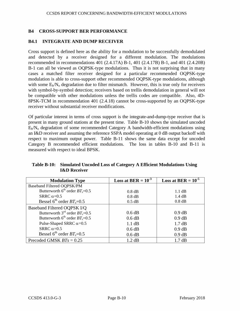
CCSDS REPORT CONCERNING BANDWIDTH-EFFICIENT MODULATIONS
CCSDS 413.0-G-3 Page B-10 February 2018
B4 CROSS-SUPPORT BER PERFORMANCE
B4.1 INTEGRATE AND DUMP RECEIVER
Cross support is defined here as the ability for a modulation to be successfully demodulated and detected by a receiver designed for a different modulation. The modulations recommended in recommendations 401 (2.4.17A) B-1, 401 (2.4.17B) B-1, and 401 (2.4.20B) B-1 can all be viewed as OQPSK-type modulations. Thus it is not surprising that in many cases a matched filter receiver designed for a particular recommended OQPSK-type modulation is able to cross-support other recommended OQPSK-type modulations, although with some Eb/No degradation due to filter mismatch. However, this is true only for receivers with symbol-by-symbol detection; receivers based on trellis demodulation in general will not be compatible with other modulations unless the trellis codes are compatible. Also, 4D-8PSK-TCM in recommendation 401 (2.4.18) cannot be cross-supported by an OQPSK-type receiver without substantial receiver modifications.
Of particular interest in terms of cross support is the integrate-and-dump-type receiver that is present in many ground stations at the present time. Table B-10 shows the simulated uncoded Eb/No degradation of some recommended Category A bandwidth-efficient modulations using an I&D receiver and assuming the reference SSPA model operating at 0 dB output backoff with respect to maximum output power. Table B-11 shows the same data except for uncoded Category B recommended efficient modulations. The loss in tables B-10 and B-11 is measured with respect to ideal BPSK.
Table B-10: Simulated Uncoded Loss of Category A Efficient Modulations Using I&D Receiver
Modulation Type Loss at BER = 10-3 Loss at BER = 10-5 Baseband Filtered OQPSK/PM
Butterworth 6th order BTs=0.5 SRRC α=0.5
Bessel 6th order BTs=0.5
0.8 dB 0.8 dB 0.5 dB
1.1 dB 1.4 dB 0.8 dB
Baseband Filtered OQPSK I/Q Butterworth 3rd order BTs=0.5 Butterworth 6th order BTs=0.5 Pulse-Shaped SRRC α=0.5 SRRC α=0.5
Bessel 6th order BTs=0.5
0.6 dB 0.6 dB 1.1 dB 0.6 dB 0.6 dB
0.9 dB 0.9 dB 1.7 dB 0.9 dB 0.9 dB
Precoded GMSK BTs = 0.25 1.2 dB 1.7 dB
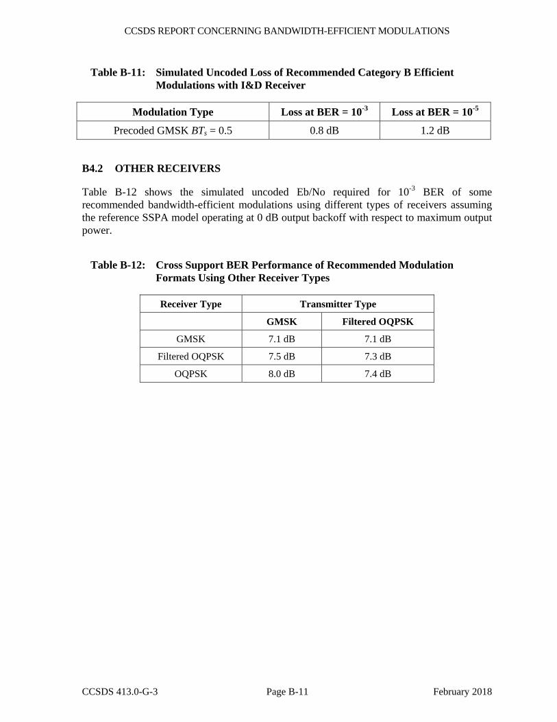
CCSDS REPORT CONCERNING BANDWIDTH-EFFICIENT MODULATIONS
CCSDS 413.0-G-3 Page B-11 February 2018
Table B-11: Simulated Uncoded Loss of Recommended Category B Efficient Modulations with I&D Receiver
Modulation Type Loss at BER = 10-3 Loss at BER = 10-5
Precoded GMSK BTs = 0.5 0.8 dB 1.2 dB
B4.2 OTHER RECEIVERS
Table B-12 shows the simulated uncoded Eb/No required for 10-3 BER of some recommended bandwidth-efficient modulations using different types of receivers assuming the reference SSPA model operating at 0 dB output backoff with respect to maximum output power.
Table B-12: Cross Support BER Performance of Recommended Modulation Formats Using Other Receiver Types
Receiver Type Transmitter Type
GMSK Filtered OQPSK
GMSK 7.1 dB 7.1 dB
Filtered OQPSK 7.5 dB 7.3 dB
OQPSK 8.0 dB 7.4 dB