barcos de concreto (inf)
TRANSCRIPT

_l I
SSC-321
This documen, has been approvedfor public release and sale; 8,s
distribution is unlimited
SHIP STRUCTURE COMMITTEE
1984

Member Agencies:
1UnitedStates Coast Guard
NavalSea Systems Command
$MaritimeAdministration
K1 AmericanBureauof Shipping
‘rMilitarySealiftCommand
PMineralsManagementService
*
& Address Correspondence-to:
Secretary,ShipStructureCommitteeU.S.Coast Guard Headquarters,(GLM/TP 13)
shipWashington,DC, 20593(202)426-2197
structureCommittee
v An InteragencyAdvisoryCommitteeDedicatedtothe Improvement of Marine Structures SR-1270
As the Ship Structure Committee has broadened its scope of projects in thepast decade, materials other than steel have been addressed. Of importance tothe marine community is the use of concrete for certain applications whereconcrete is determined to be cost effective.
This report reviews applications of marine concrete structures, research intoconcrete structures , inspection and repair of these structures and presents anextended bibliography on this topic.
Rear Admiral, U.S. Coast GuardChairman, Ship Structure Committee
486-328 Io @ E$L4MK
‘“’1..
,.,.

Technical Report Documentation Pane
1. Report No,
.—..
?. Government Accession N . 3. Rcc, p,ent’~ Cotalog No.
SSC–321
4. Title ovd iubt, tlcI
SURVEY Ol?EXPERIENCE USING REINFORCED CONCRETEIN FLOATING MARINE STRUCTURES
7- 6. ~crfarm(ng organization Code
06-5911
B.Pcr{orm, ng Organ, zatton Report No.7. Auther/t)
O. H. Burnside and D. J. Pomerening
7, Pcrforrntng Organ tizat, on Nome and Address 10. wtirk Un, f Mo. (T RAIs)
Southwest Research Institute6220 Culebra Road, P. O. Drawer 28510 ]1.CO” I,OCr O, Grant NO,
Sag Antonio, Texas 78284 DOT-CG-919837-A
IS.Type of Report and Peri~d Covered
‘“---v:::”arch”s’
12. 5ponsorinq Agency Name and Address
Commandant (G-FCP-2/TP64)U. S. Coast GuardWashington, D.C. 20590
I15. Supolemcntory Notes
The USCG a~ts as the contracting office for the Ship Structure Commit~ee
16. Abstract
*
II
This report traces the application of concrete in floating marine structures’”from its first use in the 1800’s to the present day. The various applicationswere discussed with respect ~o des~gn, construction, materials, and serviceexperience.
This report also reviews recent and current research programs, both in theUnited States and abroad, which address the use of concrete in fixed and.flrQa_tin~ma_r_ine_.s_trg.clures.
From the knowledge of applications and research activities, certain technologyareas are identified as requiring add~rional research if advances are to bemade in the use of concrete for floating marine structures. A plan is ouL–
lined for developing these identified needs into future Ship Structure Commit–tee programs.
I
17. Key Words lR. Distribution Statement
“Aconcrete (pretensioned, PosttensionedFerrocement
This document is available to the U.S.
Floating Concrete StructuresPublic through the National Technical
ShipsInformation Service, Springfield, VA
Barges Offshore Platforms22161
19. .5ecur, tY Classil, (ol this report) 20. security Clossil. , f this poge) 21. No. of Pages 22. Price
UNCLASSIFIED) UNCLASSIFIED 241
b 1 I I
Form DOT F 1700.7 (8-72) Reproduction of completed pugeouthorized

METRIC CONVERSION FACTORS
ApproxinwtmCosmrsiostsfrom Metric Msasurm
WhI you KnDw Mdticlv bf To Fid SlmbdSfmbolSrmbot Wbm YW Kasw Multipty b~
LEHGTif
LENGTHinclwm
mch~ s
Ieelyardsmiles
mil!imwra 0.04cm inwers 0.4muters 3.3mmt~rs 1.1hilmntars 0,6
m
cm
x~ mkm
incha8 “2.5faml 20
ymds 0.9
d 14a 1.6
in
rlydml
cmcm
m
km
m?~2
dkn?
hm
mkat
ml
mlmt
II
I
I~3
~3
“c
cmt itnmmrsnwtwski$omomrn
AREAAMA
in2
rl’ydamia
qwmm cwitimttmquml memln
Squm IIEdua
Squmrn kitawtwsh,ctwm
MASS [wsight]
Oums 20powd. 0,46shmt long 0.9
120M Ibl
VOLUME
~mris 0.035kil~mnn 2,2
Wlllmo {W3M kg} 1.1
02
lb.2wncm
P04n-ldsshort tms
01
rbgfmlshilotymtm
tOnn*s
VOLUME
milliliters mlllitilars 0.03 fluid ounrxs 1103
Iiwts 2.1 pints wliters 1.W quarts qt
liters 0.26 gilkms Ml
cubic memlrs 35 cubicIa*t fta
cubic nwtms 1.3 cubicyards yd3
tm2plxns 6
lnblsa PM, 15
fluid cuncos 10
Cw 0.24pinas 0.47
quarts 0,95
oalbllm 3.0cubic ket 0.03cubic yfirds 0.76
TEMPERATURE(exact)
ml
I
I
4Sp
TbspII cm
cplql
gal
flayd3
mil!ilit9r3mi14ititers
litersIlmlsliters
Iilers
cubic mewscubic meters TEMPERATURE[W4#Ct)
Celsius 9/5 I!hw+ Fahremh-i t “F
temporatur. w 32J wmF4 rature“c
“F Celsius
IempmatureFahranhmit 6/9 Iarrm
tmlmllatula subwact ing
321‘F
OF 32 96.6 Ztz
-40 0 40 aoL*lil Jlll,l~
120 160 203
l’:, ,
1 I I 1 r I
– 40 -20 0 20 40 60 ‘ 00 hOD
“c 37 Oc

TABLE OF CONTENTS
Section
LIST OF ILLUSTRATIONS
LIST OF TABLES
1.0
2.0
3.0
INTRODUCTION
1.1 Overview of Program1.2 Brief History of Reinforced Concrete
in Floating Marine Structures
REFERENCES
STATE-OF-THE-ART REvIEw.._.—__.—. .— .——
2.1 Overview2.2 Major Information Sources
REFERENCES
APPLICATIONS AND EXPERIENCE
3.1 Overview3.2 U.S. Concrete Ships Built During World War II
3.2.1 Background3.2.2 General Descriptions of Hulls3.2.3 Design Considerations3.2.4 Materials and Construction3.2.5 Proving the Designs3.2.6 Construction Costs3.2.7 Service And Experience
3.3 CONDEEP North Sea Platforms
3.3.1 Background3.3.2 Main Features of the CONDEEP Structures3.3.3 Design Considerations3.3.4 Construction Procedure3.3.5 Materials3.3.6 Experience
..f
3.4 Concrete Ships Built During World War I3.5 Other Fixed Structures
3.5.1 Ekofisk One3.5.2 Gulf of Mexico Gravity Structures3.5.3 Permanently Moored Barges
v ‘“-”
Page
vii
ix
1.1
1.1
1.2
1.6
2.1
2.12.4
2.12
3.1
3.13.1
3.13.33.83.123.163.183.18
3.21
3.213.213.253.313.353.40
3.423.44
3.443.483.48

TABLE OF CONTENTS (Cent’d.)
SectTon
3.5.3.1 ARCO LPG Floating Facility3 .5.3.2 Japanese Barge Programs
3.6 Harbor and Coastal Structures
3.6.1 Harbors and Docks3.6.2 Bridges
3.7 Barge Studies
3.7.1 Background3.7.2 Comparison of Design3.7.3 Comparison of Margins of Safety3.7.4 Fatigue Characteristics of Concrete Hulls3.7.5 Summary of Barge Designs
3.8 Floating Platform Studies
3.8.1 General3.8.2 Arctic Caisson Design
3.8.2.1 Overview3.8.2.2 Ice Forces3.8.2.3 Model Tests3.8.2.4 Arctic Caisson Results
REFERENCES
4.0 SUMMARY OF RESEARCH ACTIVITIES
4.1 Introduction4.2 United States
4.2.1 American Concrete Institute4.2.2 Portland Cement Association4.2.3 Concrete Laboratory, U.S. Army Engineer
Waterways Experiment Station (wES)
4.3 United Kingdom
4.3.1 United Kingdom’s Science Research CouncilMarine Technology Program [4.8]
4.3.2 Concrete in the Oceans Program4.3.3 Cement and Concrete Association
4.4 Netherlands Industrial Council for Oceanology(IRO) Program
Page
3.483.51
3.52
3.523.54
3.58
3.583.603.653.673.67
3.68
3.683.68
3.683.723.723.74
3.75
4.1
4.14.2
4.24.3
4.3
4.7
(SRC)4.74.104.10
4.17
vi
486-328@

TABLE Ol?CONTENTS (Cent’d.)
Section
4.5 Norway
4.5.1 Det norske Veritas (DnV)4.5.2 Norwegian Institute of Technology (NTH]/
The Foundation of Scientific and IndustrialResearch (SINTEF)
4.5.2.1 Norwegian Institute of Technology4.5.2.2 The Foundation of Scientific
and Industrial Research at theNorwegian Institute of Technology
4.5.3 Norwegian/German COSMAR Program
4.6 Treat Island, Maine, Concrete Exposure Station
4.6.1 Description of the Test Facility4.6.2 Past Research4.6.3 Study of Reinforced Beams at Treat Island4.6.4 Current Research at Treat Island
4.7 Civil Engineering Laboratory, Port Hueneme,California
4.7.1 Introduction4.7.2 Spherical Structure4.7.3 Cylindrical Structures
4.8 Fatigue
4.8.1 Introduction4.8.2 Research in the United States4.8.3 Research in the European Countries
4.9 Strength
4.9.1 Introduction4.9.2 Structural Lightweight Concrete4.9.3 Temperature Effects4.9.4 Impact Behavior
4.10 Durability of Reinforced Concrete
4.10.1 Introduction4.10.2 Permeability4.10.3 Corrosion
Page
4.21
4.21
4.31
4.31
4.35
4.36
4.37
4.374.404.414.44
4.46
4.464.464*49
4.55
4.554.554.59
4.61
4.614.644.684.69
4.69
4.694.734.74
vii
486-328 @)

TABLE OF CONTENTS (Cent’d.)
Section
4.11 Inspection and Repair
4 .11.1 Introduction4.11.2 Inspection4.11.3 Repair
REFERENCES
5.0 CONCLUSIONS AND RECOMMENDATIONS
5.15.2
APPENDIX A:
APPENDIX B:
APPENDIX C:
ConclusionsRecommendations
Definitions and Nomenclature
United Kingdom Science Research CouncilMarine Technology Program (From [4.8])
Bibliography
viii
486-328 @
Page
4.77
4*774.774.79
4.82
5.1
5.15.6

LIST OF ILLUSTRATIONS
Figure No. Page
1.1 Prestressed/Reinforced Concrete and l?errocement HullsConstructed Since 1950 (From [1.4])
2.1 Distribution of Work in the Area of Concrete in theMarine Environment
2.2 Type of Organization
2.3 Areas of Technical Involvement
2.4 Materials Research on Concrete and Reinforcements
2.5 Materials Research Reinforced, Pretensioned, andPosttensioned Concrete
2.6 Deadweight Capacity (Long Tons)
3.1 Isometric Longitudinal Section of Dry-Cargo HullsBuilt At San Francisco (From [3.6])
3.2 Comparison of Complicated and Simplified Design(From [3.2])
3.3 Hull Reinforcement Details (From [3.2])
3.4 Reinforcing Details - National City Hulls (From [3.2])
3.5 CONDEEP Platforms, Geometry and Location (From [3.10])
3.6 General Features of a 3-Tower CONDFJ3PPlatform
3*7 General Design Procedure (From [3.13])
3.8 Star Cell Geometries (From [3.14])
3.9 Slip-Forming of Cell Walls (From [3.16])
3.10 Vertical Cross-Section and Horizontal Half-Sectionof the Ekofisk One Facility
3.11 Ekofisk Oil Storage Caisson Under Construction(From [3.24])
3.12 Concrete Gravity Platform for Gulf of Mexico(From [3.26])
3.13 Midship Section, 65,000-Ton Concrete LPG Facility(From [3.28])
1.5
2.2
2.7
2.7
2.8
2.9
2.11
3.5
3.5
3.7
3.7
3.23
3.24
3.26
3.29
3.29
3.46
3.47
3.49
3.50
ix.—

LIST OF ILLUSTRATIONS (Cent’d.)
Figure No.
3.14
3.15
3.16
3.17
4.1
4.2
4.3
4.4
4.5
4.6
4.7
4.8
4.9
4.10
4.11
4.12
4.13
4.14
Hull Construction Scheme of Arco LPG Barge(From [3.28])
Longitudinal and Transverse Sections of Genoa’sFloating Dock (From [3.32])
Typical Pontoon Section (From [3.35])
Isometric View of Proposed Arctic Caisson(From [3.47])
Graphic Representation of Cracking and Corrosion--Beams 4 and 5 (From [4.31])
Strength Increase of Concrete in Spherical Structures(From [4.33])
In–Plane Cracking of Thick–Walled NegativelyBuoyant Spheres (From [4.33])
Compressive Strength Gain of Concrete in DifferentEnvironments (From [4.34])
Total Water Intake for Spheres in the Ocean For LongTime Periods (From [4.34])
Design Guide for Predicting Implosion of ConcreteCylinder (From [4.37])
Relationship Between E.= and f: (From [4.37])
Fatigue Endurance of Concrete in PrestressedConcrete Hull (From [4.42])
Fatigue Endurance of Reinforcement in PrestressedConcrete Hull (From [4.42])
Reinforcing Details of Tesf Beam (From [4.45])
Fatigue Tests Loading Arrangements (From [4.45])
Fatigue Test Results on Reinforced Concrete Beamin Sea Water (From [4.45])
Deterioration of a Concrete Structure In Sea Water(From [4.56])
Effect of Water-Cement Ratio on Permeability(From [4.62])
Page
3.50
3.53
3.56
3.70
4.43
4.48
4.48
4.50
4.50
4.52
4.52
4.57
4.57
4.62
4.62
4.63
4.70
4*75
x

LIST 0)?TABLES
Table No.
2.1
3.1
3.2
3*3
3.4
3.5
3.6
3.7
3.8
3.9
3.10
3.11
3.12
3.13
3.14
3.15
3.16
3.17
Survey of Fixed Offshore Concrete Platforms, EitherInstalled or Under Construction in the North Sea
Principal Features of the U.S. Concrete Ship Programof World War 11 (From [3.1])
Concrete Ship Program - World War II (From [3.4])
Design Bending(From [3.4])
Allowable Unit
Moments (BM) and Shearing Forces
Stresses, Psi (From [3.5])
Typical Physical Properties of Lightweight Aggregates
Used in U.S. Concrete Ships (From [3.16])
Typical Mix Design for Concrete Used In U.S. ConcreteShips (From [3.6])
Engineering Properties of Concrete Used in U.S.Concrete Ships (From [3.16])
Cost Summary - Construction and Facilities(From [3.4])
CONDEEP Structures (From [3.9, 3.12])
Main Figures on the Construction of the TCP2 Platform(From [3.11]]
Mix Particulars and Compressive Strengths forSeveral North Sea Concrete Platforms (From [3.17])
Typical Properties of Cements From Norcem(From [3.17])
Assumed Wave Heights and Stress Limits, ArcoFacility (From [3.28])
Plant Barges (From [3.31])
Comparison Between Concrete and Steel HullCharacteristics (From [3.42])
Summary of Allowable Stresses (From [3.42])
Static Balance Comparison of Concrete and SteelHulls (From [3.42])
Page
2.3
3.2
3.4
3.10
3.11
3.14
3.14
3.14
3.19
3.22
3*33
3.36
3.38
3.49
3.59
3.59
3.62
3.64
xi
486-3z$@
-1/, )’1
<;’”

LIST OF TABLES (Contrd.)
Table No.
3.18
3.19
3.20
3.21
4.1
4.2
4.3
4.4
4.5
4.6
4.7
4.8
4.9
4.10
4.11
4.12
4.13
4.14
Comparison Between Deterministic Factors of Safety -Concrete Versus Steel Hulls (From [3.42]}
Comparison of Probabilities of Failure and SafetyIndices (From [3.42])
Performance in Open Water for 200,000-TonDisplacement Caisson (From [3.47])
Performance in Ice-Covered Waters (From [3.47])
Research in Progress as Reported by ACI Committee 115
Research by Country as Reported by ACI Committee 115(From [4.2])
Research Projects Directly Applicable to MarineConcrete Structures as Reported by ACI Committee 115
Research Projects Directly Applicable to MarineConcrete Structures as Reported by Concrete Laboratory,U.S. Army Waterways Experiment Station (From [4.7])
Phase I of UK Concrete in the Oceans Program
Phase II of UK Concrete in the Oceans Program
Research Areas of the Cement and Concrete Association
Research Programs of the Cement and Concrete AssociationApplicable to Floating Marine Structures (From [4.11])
Past and Current Netherlands Marine TechnologicalResearch in Concrete (From [4.16])
Research Programs at Det Norske Veritas Applicable toFloating Marine Structures (From [4.18])
Norwegian/German COSMAR Program (From [4.18])
Ultlmate Load Properties of Beams Tested in Flexure(From [4.31])
Type of Concrete
Comparisons of Lightweight and Normal Weight Concrete(From [4.52])
Page
3.66
3.66
3.71
3.73
4.4
4.4
4.5
4.8
4.11
4.16
4.18
4.19
4.22
4.25
4.38
4.43
4.64
4.66
xii ...,,,. ,, ,.L,,
‘,-4-

1.0 IXTTRODUCTION
1.1 Overview of Prbgram
Since 1848, when the first concrete boat was built by J. L. Lambotin France, concrete has been used sporadically for floating marine
structures. Shortages of plate steel during World War I and World War 11led to the construction of concrete lighters and barges, although thetotal number of vessels and tonnage was very small compared with steelships. Since World War II, one primary use of concrete in the marineenvironment has been in the construction of oil drilling, production,and storage facilities in the North Sea area, and in LPG/LNG applications.The wide diversity in past and potential applications for both fixed andfloating structures has generated a large amount of research, design,and construction.
-1In this country, information on the use of concrete in floating
qstructures is scattered, and there exists no survey which gives a summaryof the state of technology. Consequently,
‘%those areas of research required.
!$! to extend current concrete technology to ship construction have not beenidentified. This report is to provide such a state-of-the-art survey so
t that these research areas can be identified. Current information on the
* use of concrete in the marine environment which is available in the openliterature was reviewed. This, in conjunction with information obtainedfrom design, construction, maintenance, certification, and researchagencies, was used to provide an information base for the entire study.These results are summarized in Chapter 2.0 of this report.
Chapter 3.0 reviews in detail the design, construction, and serviceexperience of two extensive programs on the marine use of concrete, namely,the World War II United States concrete ships and the North Sea CONDEEPplatforms. This chapter also discusses other current and future applicationssuch as ships, barges, harbor and coastal structures, and energy explorationfacilities. Experience with a number of concrete ships built in the WorldWar I and 11 periods is cited. It should be remembered that, because ofthe elapsed period and general unavailability of technical data, it isdifficult to correlate this experience with the design criteria,construction procedures, or service history of these ships.
Chapter 4.0 summarizes past and current research activities applicableto floating marine structures. This chapter, along with the informationgathered as part of the review of past, current, and future applications,forms the basis for recommending a research plan for future Ship StructureCommittee activity. These recommendations are given in Chapter 5.0.
Appendix A contains a list of technical terms and definitionsapplicable to this report, Appendix 13describes applicable research inconcrete being performed in the United Kingdom Science Research CouncilMarine Technology Program, and Appendix C is the bibliography compiledas part of the information survey.
my,$486 - ,30.-

Concrete is one of the oldest man-made building materials. Excavationsin the Mediterranean area indicate that concrete made from naturalpozzolanic cement has been used for over 2,000 years in structures, many.——--———— ——.--——. ............——of whi~h we?e exposed to seawater.
———.. ..The development of portland cement,
first patented in England in 1824, was essential for the continueddevelopment of concrete structures. The development of reinforced concrete
followed, with its invention generally attributed to Joseph Lambot, aFrenchman, who applied reinforced concrete to the fabrication of a smallferrocement boat. He built his first small rowboat in 1848 and later
: exhibited a similar boat at the Paris Exposition of 1855. Ferrocementwas also used by other builders In Europe and America during the late1800’s and early 1900’s. The sloop Zeemwuw, built in 1887 by Gabellini
and Boon, was finally taken out of service in 1968 [1.1].t The ConeFete,constructed in the early 1900’s, was the first ferrocement vessel usedby the United States government. The 5.5-m (18-ft) long boat had a hullthickness of 19 mm (3/4 in.) and was capable of 10 knots service on theGreat Lakes [1.2]. Since 1848, a large number of ferrocement vesselshave been constructed and have performed satisfactorily [1.3, 1.4].
The first examples of the use of the more conventional cast-in-place,bar-reinforced concrete were several barges built in Italy by Gabellini.A 50-ton lighter built in 1902 and the 150-ton L{gtw{d, which was in servicefrom 1905 to 1917, are typical. N. K. Foagne, of Norway, built the firstlarge seagoing vessel, the Nam6enfjbrd, a 25.5-m (84-ft) long ship launchedin 1917 [1.1]. Searle [1.5] refers to a number of concrete pontoons andbarges constructed during the period leading up to the first world war.
During World War I, the United States, the TJnitedKingdom, and the
Scandinavian countries built a number of reinforced concrete vessels.These vessels copied the traditional framing of steel ships of the periodand therefore were grossly overdesigned and overweight. The largest castreinforced ship, the Selma, was built in the United States in 1919. Afteronly a few years’ service, this 6340-ton, 130-m (434-ft) long ship wasscuttled in the shallow water of Galveston Bay. A study of her hull in1953 showed little deterioration of the concrete [1.1]. The majority ofships and barges built during this period survived well with one notableexception, the Awn~staee, built in Great Britain in 1919 [1.1]. Whensurveyed in 1968, the hull was found to be badly spalled and the internalframes almost completely devoid of concrete. The primary reason was thepoor quality of concrete used during the construction of this vessel.
Overall, about 85,000 tons of seagoing shipping were built duringWorld War I, not counting several hundred barges, lighters, pontoons,
tNumbers in brackets denote references listed at the end of each chapter.
1.2
48&328@
“-.,
,,’ ,“,:/,<.2

and a few floating docks. Various construction procedures were used forthese vessels, including guniting, slip-forming, and prefabrication.Concrete shipbuilding programs came to a halt following World War T becauseof a surplus of merchant ship tonnage. No new major construction wasundertaken until World War 11.
The second world war once again created a need for more shipping.To partially satisfy this need , concrete was again used because of thescarcity of steel plating. The majority of construction was performedin the United States, with efforts concentrated in the area of towedvessels , although 24 self-propelled cargo ships were constructed. Onehundred four seagoing vessels were constructed in the United States, witha total of 488,000 total deadweight tons. The first prestressed concretevessels built in the United States were a landing craft and a barge.Precast cells were laid in a checkerboard fashion with the prestressingsteel placed between the cells. After tensioning, the steel was coveredwith a layer of gunite concrete [1.6]. During the same period, Germanyconstructed several 500-ton prestressed barges. The flat portions ofthe bottom and sides were cast on the ground with pretensionedreinforcement. The sides were then bent up, and the joints, stem, andstern were cast in place. Construction of reinforced concrete vesselswas also carried out in Britain and the USSR.
Following World War 11, construction of concrete vessels againdeclined. Nervi, in Italy, constructed a number of ferrocement vesselsduring the period immediately following the war. The Nwwwlle, a 12.5-m(41-ft) long ketch, had a shell thickness of only 12 mm (1/2 in.). Thisketch, built in 1948, is still in excellent condition [1.1]. Since thattime, a large number of ferrocement boats have been built, mainly by do--it-yourself yachtsmen. Recently, ferrocement construction techniqueshave been used in underdeveloped countries for the production of barges,pontoons, boats, and buoys [1.7, 1.8].
Reinforced concrete, as distinct from ferrocement, has not been usedextensively since World War 11 [1.7]. Barges have been built for use inthe Gulf of Mexico, as well as pontoons and floating docks in other partsof the world. Reinforced concrete has been used only where the additionalweight over that of steel structures i-s-notimportant.
Since World War II, development has been primarily in the area ofprestressed concrete vessels. Early examples are the cellular pontoonsbuilt for Le Havre Harbor in 1951 and a posttensioned pontoon 55 m longby 24 m wide by 5.35 m deep (180 ft x 78 ft x 17 ft) constructed in Belgiumto carry a small oil refinery in Libya [1.1]. Alfred Yee designed, toAmerican Bureau of Shipping (ABS) standards, and patented a 2000-toncapacity barge to carry either dry cargo or petroleum products. Typicaldimensions are:
1.3
486-328 @

Length overall 60 m (198 ft)
Beam 17 m ( 57 ft)Depth 4m(13ft)
Nineteen of these barges were built between 1964 and 1966, and they hav,eprovided good se~vi9at__l.qy_zggual,_rnaZn!~nanc_e-c.oSt..-[l._9~+_AdditiOn&._=__ .... . .---- ———.-...prestressed concrete barges were built in New Zealand in 1969 f_o.rservice—..
Marine Concrete Structures, New Orleans~-”-h~s—”——’”—-—i~t””hk SoutFP~c~f–i–c”.––——Y–”’–—constructed over 400 concrete barges and platforms with a wide varietyof superstructure amounted plants. More recently, in 1976, a precast/prestressed concrete floating platform was constructed in Washington andtowed to the Java Sea [1.6]. The structure, 140 m long, 41.5 m wide, and17.1 m deep (461 ft x 136 ft x 57 ft), was designed by ABAM Engineers,Inc., and constructed by Concrete Technology Corporation. The vessel,designed as a permanently moored facility for storage and processing ofLPG, is posttensioned both transversely and longitudinally. Design andconstruction of the vessel were carried out under ABS rules. D
Figure 1.1 presents results from a recent survey by Barrington andHarrison [1.4] on barge and pontoon prestressed,hulls constructed since 1950.
reinforced, and ferrocementThe ferrocement hulls are small, usually
less than 27.5 m (90 ft) in length. For the remaining structures, theprestressed exceed the reinforced hulls by.a ratio of over two-to-one.The 137.5-142.5-m length class contains the prestressed floating LPGfacility for the Java Sea mentioned in the previous paragraph and twofloating reinforced concrete ship repair docks in the USSR.
Concrete floating bridges are another use of concrete in the marineenvironment. Three precast concrete multi-pontoon structures built in1939, 1955, and 1962 have been in service in the Seattle, Washington,area. The precast pontoons, 101 m long, 20 m wide, and 4.8 m deep (360ft x 66 ft x 15 ft 8 in.)dock.
, were launched following construction In a gravingAfter the superstructure was constructed, the pontoons were towed
to the bridge site and posttensioned together. The first two bridgesbuilt in 1939 and 1945 have provided good service, while the third bridge,built in 1962, failed in 1979 [1.10]. The finding of the survey teamwas that failure was produced by a combination of a very severe storm(producing dynamic response and movemen~ of the anchors, flooding of thepontoons), and deterioration of streng”thdue to corrosion.
More recent developments in the use of concrete in the marineenvironment have been primarily associated with fixed structures usedfor oil production and storage facilities. These fixed structures willbe discussed in more detail later in this report.
The purpose of this brief historical review has been to demonstratethe variety of applications for concrete in the marine environment overthe last 130 years. With few exceptions, the concrete structures haveperformed well under the loads of the marine environment. Durability,
..-,‘,g/:/
“’L._/’
.. ..—. —..—-.-

oi
!)0
au
70
60
50
40
30
20
10
2.5
U:::x
~.:.:FEH[{#CEMENr:::f.~.......
laPRESTRESSIiDCONCRHE
II REINFORCED CONCRETE
ROLL I,ENG’TR(M)
FIGURE 1.1 PRESTRESSED/REINFORCED CONCRETE AND FERROCEMENT HULLS
CONSTRUCTED SINCE 1950 (FROM [1.4])
.
[
‘)-’-..,,q.

watertightness , vibration control, seaworthiness, and material strengthsand weaknesses have been demonstrated. Future advances in the use of
concrete will require improvements in design and analysis methods, materialproperties, maintenance techniques, and construction procedures. These
technical advances are, of course, directly coupled to the economicfeasibility of using concrete in floating marine structures. Areasrequiring further study and research must be based on both past historyand expected future applications. The remainder of this report will lookat these areas in more detail.
REFERENCES
1.1
1.2
1.3
1.4
1.5
1.6
1.7
1.8
1.9
1.10
Morgan, R.G., “History of and Experience with Concrete Ships,”Comf@r-enc@ ah Cdtr&rete Shi”p% and T-To=tffigStrtitttires,pp 3-16,Berkeley, California, Sept. 1975.
T.iu, T.C., and McDonald, J.E., ‘*Concrete Ships and Vessels - Past,Present, and Future,” Concrete Laboratory, U.S. Army EngineersWaterways Experiment Station, Misc. Paper C-77-12, Vicksburg,Mississippi, Oct. 1977.
Morgan, R.G., “Development of the Concrete Hulls,” Cbntrete Afloat,The Concrete Society, London, 1977.
Barrington, K.E., and Harrison, R., *’Survey of the OperationalExperience Achieved with Prestressed Concrete/Reinforced Concreteand Ferrocement Barge and Pontoon Hulls Since 1950,” SunderlandPolytechnic, March 1981.
Searle, A.B., “Reinforced Concrete Ships, Barges and Pontoons,”
Concrete and Constrtictional Engltieertng, London, Supplement, Part1, Nov. 1918; Part II, Dec. 1918.
Anderson, A.R., “Prestressed Concrete Floating Structures (State-of-the-Art) ,“ SNAME Spring Meeting, pp 123-144, Vancouver, B.C.,May 1975.
Curry, R., “Concrete as a Ship and Boatbuilding Material,” Symposiumon Indian Shipbuilding, Calcutta, India, Feb. 1980.
Gopalaratram, V.S., Pama, R.P., and Vans, J., “A Review of MarineApplications of Ferrocement in Asia,” Concrete Ships and FloatingStructures Convention, Rotterdam, Nov. 1979.
Sare, P.M., and Yee, A.A., “Operational Experience with Prestressed __——--- ..-——.——.._. ... —..—-—-Concrete Barges,” Contret&’Aflbat, London, 1977.
.-.
“Hood Canal Floating Bridge, Phase 1 Report, Determination of theCause of Failure,” for State of Washington, Department ofTransportation, Tokola Offshore and Earl and Wright ConsultingEngineers, Aug. 1979.
1.6
486-328@

2.0 STATE-OF-THE-ART REVIEW
2.1 Overview
Developments in the use of concrete in the marine environment havebeen spread throughout the world. Figure 2.1 gives an indication of thediversity of countries and their areas of involvement in this technology.
Exploration of the North Sea oil reserves has prompted the designand installation of large-scale concrete structures to withstand severeenvironmental conditions. Table 2.1 shows the various structures installedor under construction. The severe environment and unique designrequirements of these structures have led to a large amount of researchin the use of concrete in the marine environment. Classification andregulatory agencies in Europe have anticipated and responded to the expandeduse of concrete in both fixed and floating structures by developing codesand regulations. Fo$ example, Det norske Veritas (DnV) [2.1, 2.2],Norwegian Standards Federation [2.3], United Kingdom Department of Energy(UKOOE) [2.4], l’e~e~ation International de 1< Pr;contrainte (FIl?) [2.5],and Bureau Veritas (BV) [2.6, 2.7] have rules concerning design,construction, and inspection of marine concrete structures.
As mentioned in the first chapter, during the two World Wars theUnited States constructed the largest number of oceangoing concretevessels. Construction of concrete marine structures after World War II
_... .———..——
has been limited. Exceptions are the concrete barges and platforms forthe Gulf of Mexico, the ARCO LPG processing plant, the floating bridgesin Washington State, and the barges designed for use in the Philippines.Recently the American Concrete Institute (ACI) has published guidelinesfor the design and construction of fixed offshore concrete structures[2.8]. Much of the information. was drawn from sources such as the AmericanPetroleum Institute’s (API) [2.9] recommended practice for fixed offshoresteel platforms> and.European. guidelin~~jD[~.Ll~,and r2.51. The_ACI docum~n~_____————.—con~ains chapt-ers—o=”-tia-terialsand durability, loads, design and analysis,foundations, construction and installation, inspection and repair, andappendices on environmental loads and design for earthquakes. The AmericanBureau of Shipping (ABS) has also been active In developing analysisprocedures [2.10] and rules for building and classifying concrete vessels.A draft of these rules is complete and is currently being reviewedinternally at ABS [2.11].
Since World War 11, the USSR has published little in the openliterature on the use of concrete for marine vessels. Work by Bezukladov[2.12] in the area of ship hull design and construction seems to be themost significant. Barrington and Harrison [2.13], in addition to thefloating reinforced concrete ship repair docks mentioned in Chapter 1.0,
2.1
4$6-328@

3g
IQ.
M
.i:1
_—J&z___
Design ?
Construct ion h
Research “+
Certification A
FIGURE 2.1 DISTRIBUTION OF WORK IN THE AREA OF CONCRETEIN THE MARINE ENVIRONMENT

TABLE 2.1 SURVEY OF FIXED OFFSHORE CONCRETE PLATFORMS,EITHER INSTALLED OR UNDER CONSTRUCTION IN THE NORTH SEA
TypeofDesignLocation
1 DORISEXOF18R1 (N)
2 CONDEEPBERYLA(UK)
3 CONDEEPBRENTB (UR)
4 DORISFRIGGCDP1(UK)
5 SEA TANK
BRENT C (UK)
6 SEATANKFRIGGTP1(UK)
7 SEATANKCORMORANTA(UK)
8 CONDEEPBRENTD (UK)
9 ANDOCDUNLINA (UK)
10 CONDEEP
STATFJORDA(N)
11 CON’DEEPFRIGGTCP2(N)
12 DORISFRIGGMP2(UK)
13 DORISMINIAN(UK)
14 PUB3PETROBRAS
15 PUB2pETRoB~S
16 PAG2PETROBRAS
17 CONDEEPSTATFJORDB(N)
N . NorwayUK = UnitedKingdom...
MainFunction
..... .,,.
Storage
Drilling,pro-duction,storage
Drilling,pro-duction,storage
Drilling,Com~+zmession, product.
Drilling,pro-duction,storage
Production
Drilling,pro-duction,stor’-
age.;
Drilling,Pro-duction,storage
Drilling,Pro-duction,storage
Drilling,pro-duction,storage
Treatment,com-pression,pro-
duction
Compressionstation
Drillingandproduction
Drilling,pro-duction,storage
Drilling,pro-duction,storage
Drilling,pro-duction,storage
Drilling,pro-duction,storage
DesignWaveHeight(m)
24.0
29.5
30.5
29.0
30.5
29.0
30.5
30.5
30.5
30.5
29.0
29.0
31.2
11.0
11.0
11.0
32.0.;.
mDepth(m)-.
70
120
142
96
142
104
152
142
152
149
104
94
139
15
1$
15
149
Approx.ConcreteVolume(m3)
90,000
55,000
65,oOO
60,000
105,000
70,000
115,000
65,000
89,000
88,oOO
50,000
60,000
142,000
15,000
15,000
15,000
135,000
Base)iameter
(m)
92
100
100
101
100
72
100
100
104
110
100
101
140
50
50
50
169
StorageCapacity(mill.barr.)
1.0
0.93
1.0
0.65
1.0
1.0
0.85
1.3
0.125
0.125
0.125
2.0
[instal-lationYear
1973
1975
1975
1975
1978
1976
1978
1976
1977
1977
1977
1976
1978
1977
1978
1978
1981
2.3

list six reinforced concrete, permanently moored floating hulls between20 m (65 ft) and 77 m (250 ft) lon~ and four free-floating prestressedconcrete hulls in the 23-m (75-ft) to 65-m (210-ft) length class builtin the USSR after 1950.
In Asia the primary work has been in the development of ferrocementpontoons, buoys, and boats. For the underdeveloped countries in thisregion, the low-technology, labor-intensive techniques of ferrocementconstruction are very applicable.
Japan is also Involved in the development of ferrocement techniquesfor small craft. They have also built several experimental prestressedconcrete barges 10 m (33 ft) to 24 m (78 ft) in length, of which at leasttwo have been classified by the Japanese ship classification society,Nippon Kaiji Kyokai [2.14, 2.15]. In addition, the design and constructionof several harbor and coastal structures have been undertaken in prestressedconcrete. An example is the Tomakomai industrial development project inJapan [2.16].
The offshore coal-loading terminal completed in 1975 at Hay Point,Queensland, Australia, is an example of a major floating concrete structurethe Australians have designed and constructed [2.17]. The terminal,constructed 2000 m (6500 ft) from shore, using 10 prestressed concretecaissons, provides a berth for 120,000 dwt ships. A large number offerrocement sailing vessels have been constructed in Australia, and ideashave been developed for large floating plant facilities [2.18].
Thfs section and Chapter 1.0 give an indication of the range ofinterest and experience in both fixed and floating concrete structuresthroughout the world. Since this study is primarily a state-of-the-artreview, it is necessary for the information to be as up-to-date as possible,and several types of sources were used. The first was the open literature,including reports, papers, and proceedings of conferences concerned withuse of concrete in the marine environment. Inquiries were made toorganizations and individuals currently involved with this technology toobtain the most recent or unpublished information. In addition, personalcontact with a number of individuals in the United States and Europe wasestablished. The following sections in this chapter describe theinformation sources and discuss the findings from this review.
2.2 Major Iiiform~tiOn SourC@s
The first attempt to categorize the current literature was acomputerized literature review of the Lockheed Information System DIALOGdata base. In this data base, the Computerized Engineering Index, theInformation Service in Mechanical Engineering, and the Government ReportsAnnouncement were searched. In addition, the Maritime Research InformationService data base was automatically scanned. Concurrent with the automatedliterature search, a search of the SWRI llbrary was made of the proceedingsand journals of various technical societies such as the American Society
2.4

of Civil Engineers (ASCE), American Concrete Institute (,ACI),and the
Society of Naval Architects and 14arineEngineers (SNAME). From this search,technical conferences directly applicable to floating concrete structureswere identified. These included:
Offshore Technology Conference● 1969-1981 (Yearly)
Houston, Texas
F~d6ration International de l; Pre’contrainte (FIP) Congress● 6th, 1970
Prague, Czechoslovakia● 7th, 1974
New York, New York● 8th, 1978
London, England
Gastech - The International LNG/LPG Conference and Exhibition● 1974-1981 (Yearly)
Conference on Concrete Ships and Floating StructuresContinuing Education in Engineering,University of California Extension
. September 15-19, 1975Berkeley, California
Design and Construction of Offshore StructuresConference of Institution of Civil Engineers
. October 27-28, 1976London, England
Conference on Behavior of Offshore Structures (BOSS)● BOSS ’76
August 2-5, 1976Trondheim, Norway
● BOSS ’79August 28-31, 1979London, England
Concrete Afloat● March 3-4, 1977
London, England
Brasil Offshore ’799 October 8-12, 1979
Rio de Janeiro, Brasil
Concrete Ships and Floating Structures Convention. November 12-14, 1979
Rotterdam, Holland
International Conference on Performance of Concretein Marine Environment
● August 17-22, 1980New Brunswick, Canada
2.5
486-328 @

International Colloquium on the Strengthof Concrete in the Ocean
o October 8-10, 1980Brest, France
Floating Plants, 1st International Conferenceo October 13-15, 1980
Paris, France
l?rom this literature review, organizations and individuals workingin the areas of concrete applications, design, materials research,construction inspection, and maintenance were identified. To obtain themost current state-of-the-art information, over 160 individuals werecontacted by mail in the following countries: Australia, Belgium, Canada,Denmark, Finland, France, West Germany, Italy, Japan, Netherlands, NorwaY~Sweden, Venezuela, Yugoslavia, the United Kingdom, and the United States.Forty-one percent of those contacted responded; an additional 19 percentof the individuals contacted indicated they were no longer active in theconcrete technology field or were unable to respond because of theproprietary nature of their work.
A summary of the findings from this survey is presented in Figures2.2 tO 2.5. The ordinate of each graph shows the percentage oforganizations* which indicated involvement or interest in a given area.Responses could have been given in more than one category, so that thetotal does not necessarily equal 100 percent. Only trends, and not absolutequantities, should be interpreted from these results due to the limitednumber (67) of responses.
In Figure 2.2 the responding organizations were divided into threemajor geographical groupings according to their area of technicalinvolvement. The first, including the USA and Canada, accounted for 46percent of the responses. Thirty-seven percent were from the West Europeancommunity. The third group, with 17 percent of the responses, representedAustralia and Japan.
Of the individuals responding, Figures 2.2 and 2.3 indicate thegreatest number are associated with research type organizations involvedin materials research and testing. The second largest group consists ofthose involved in design , consulting, and construction. Individuals activein certification, operation, inspection, maintenance, and repair of thesestructures form the majority of the remaining responses. This distributionis consistent with the open literature where the majority of articlesare concerned with materials research, testing, and design.
Only a limited number of papers are available in the area ofconstruction and maintenance. This is not to say that the state~of--theart in these areas is not as developed as in the material and design areas,
*In this section the terms organization and individual are synonymous.
.—26.............

80 II Total
n USA, Canada70
60
50
40
30
20
10
0
BGreatBritain,Norway,Sweden,....
... Netherlands,Denmark,Belgium,France, West Gecmany,ItiL:/
El Australia,Japan
ill:::::::.:;‘.:.:.:::~
.
So..
E.9
-— u
FIGUW 2.2 TYPE Ol?ORGANIZATION
II Past
i P~esent
U:.... Future
501
Lo
::::!.y:::::::.:.:.::::::::::::::::.:,:.:::...~.:.::::::...
40
30
20
10
0 I:>:k.y:::y:.:.:.:.:.:+:.::;:::....+.::::::L:.:.:.::::::::.>;
$:..:.:.:::~:::J:
., ..—
FIGURE 2.3 AREAS OF TECHNICAL INVOLVEMENT
---2..7
486”328 @

80
70
60
50
40
30
20
10
0
Past Research
CurrentResearch
FutureResearch(Firm)
Identifiedas Reauirin=AdditionalResearch
IldIL.:::..r...,..:< ;::: !::
:.: /.
Concrete
—.., ..
1111:::::::::::::::...+;!:
Past Reeesrch
CurrentResearch
FutureResearch(Firm)
Identifiedas RequiringAdditionalResearch
m
(b) Reinforcements—
FIGURE 2.4 MATERIALS RESEARCH ON CONCRETE AND REINFORCEMENTS
2.8

Fasc Rweurch
Cutrent Rnsaarch
Future Research (Fi~)
Idmnrified as Requiting
Additionn.1Resaarch
(a) Reinforced Concret.
u Pa8ERasearch
~ F.ture M.eat.h (Firm)
ElIdencificd as E-quiringadditional Research
(b) PrI-_h_IsionedCmcrem
Paint Research
Cu=e!lc Research
Future Research (Firm)
Identified as ?.equiri”g
Additional Rceenrch
(c) ?osc-Tensianed COncret*—-— . .-.. . ._
FIGURE 2.5 MATERIALS RESEARCH ON REINFORCED, PRETENSIONED,
AND POSTTENSIONED CONCRETE
2.9
486 -328 @

but that publications are limited. In fact, current practices in slip-forming and precast construction are extremely sophisticated and efficient.
It is interesting to note from Figure 2.3 that while the fields ofmaterials, consulting} design, and construction show the largest activity,present and future interest in these areas is declining. On the otherhand, the other fields, such as maintenance, repair, and inspection, showthe opposite trend -- low starting base, but increasing interest.
Figure 2.4 summarizes the responses for the individual materialsconstituting a concrete structural system, namely, plain concrete andreinforcements. Certainly concrete has received the greatest amount ofattention, and interest in most technical fields is remaining level ordeclining, probably because of the great amount of past work. The exceptionfs in the area of repair, where actfvlty and interest are increasing.
Figure 2.5 is revealing in that it gives the respondeest views ofmaterials research in the areas of reinforced, pretensioned, andposttensioned concrete. Certainly the greatest activity has been inreinforced concrete. Temperature effects include both high and lowtemperature characteristics. Interest in cracking, corrosion, andpermeability has been significant because of the requirement to providea permanent barrier both for internal storage and to keep sea water out.Interest in fatigue has been stimulated by the repeated loadings encounteredunder wave action, and the long service life requirements have dictatedthe use of design procedures incorporating fatigue procedures.
However, research interest in reinforced concrete for floating marinestructures (Figure 2.5(a)) seems to be declining, with the exception of
cracking~ permeability, and repair, which are remaining about level. Sincemore and more concrete structures are being built, the interest in repairtechniques should continue.
Pre and posttensioned concrete, on the other hand (Figure 2.5(a &b)), show less past and current research activity, but a projected increaseof interest in almost all fields. This trend probably reflects therealization that if concrete is to be used in ships or barges for materialtransport, then the total hull weight must be reduced. This would increasethe deadweight/displacement ratio towards that of an all-steel vessel.Since the deadweight/displacement ratio Is a measure of how efficientlya ship can transport cargo, the problem of hull weight must be overcomeif concrete Is to compete successfully with steel. For example, thereinforced concrete hulls built during both World Wars have a legacy ofbeing overweight. No improvements were made in this area during the 20-year period between World Wars I and 11 despite experience with land-based structures, higher allowable concrete and steel stresses, andconstruction techniques. The weight problem is clearly illustrated inFigure 2.6, where the deadweight/displacement ratio is plotted againstdeadweight capacity for several classes of steel vessels and the WorldWar I and 11 concrete ships. Although the ARCO prestressed concrete bargeis not used for LPG transport, it is shown for comparison purposes.
2.10

I I 1 I 1 I I I I I 1I
1 I 1
-.
.
.
.
A
o
1
A ‘O
h1 I I I I I
ships
A WWII- Tanker
O WWII - LibertyShip
❑ C2-TypeCargoVessel(1940’s)
~ C3-Type Cargo Vessel (1940’s)
6 First ContainerShips (1970’s)
h RO/ROShip (1970’s),
A LNG Carrier(1970’s)
ConcreteShipsand Plants
~ IiTJI- ‘CapeFear”
. WWI - Selma
■ WWII - Average of Self-Propell(and Towed Vessels
h ARCO LPG Facility
I I 1 I I I b
4,00!38,OOO 16,000 24,OOO 32,000 40,000 48,000 56,000——...-.—.—...... . . . .. ..-—.
FIGURE 2.6 DEADWEIGHT CAPACITY (LONG TONS)
2.11

Prestressing and posttensioning are certainly techniques of utilizingconcrete and reinforcements more efficiently by introducing initialcompressive loads so that the net working stresses remain essentially incompression. Hence, the tensile loads which cause cracks are avoided.
In addition to the responses received by mail, the projectinvestigators had the opportunity to make followup Inquiries by telephoneand personal visits. For example, organizations involved in materialsresearch, design, testing, and certification were visited in the-Netherlands, France, Norway, Scotland, and England. These visits providedthe opportunity for direct dialogue with the European researchers concerningthe use of concrete in floating marine structures and a chance to learnfirsthand about many ongoing projects. This research work, as well asactivities conducted in the United States , will be reviewed in Chapter4.0.
REFERENCES
2.1
2.2
2.3
2.4
2.5
2.6
2.7
2.8
2.9
“Rules for the Design, Construction and Inspection of OffshoreStructures,” Det norske Veritas, H&ik, Norway, 1977.
“Guidelines for the Design, Construction and Classification ofFloating Concrete Structures,” Det norske Veritas, I@vik, Norway,1978.
‘“Norwegian Code of Practice for Concrete Structures, Computationand Design,” Norwegian Standards Federation, NS3473, Norway, 1978.
“Offshore Installation: Guidance on Design and Construction,” U.K.Department of Energy, 1977.
“Recommendation for the Design and Construction of Concrete SeaStructures,” FIP, 3rd Edition, FIP/6/1, Cement and ConcreteAssociation, Wexham Springs, Slough, England, .Tuly1977.
“Rules and Regulations for the Construction and Classification ofOffshore Platforms,” Bureau Veritas, Paris, France, 1975.
“Classification and Survey of Concrete Ships and Pontoons,” BureauVeritas, Guidance Note NI 175 CfiT4,Paris, France, 1!379.
“Guide for the Design and Construction of Fixed Offshore ConcreteStructures,” ACI Report of Committee 357, ACI Journal, Dec. 1978.
“API Recommended Practice for Planning, Designing, and ConstructingFixed Offshore Platforms,” API IU?2A, 9th Edition, American PetroleumInstitute, 1977.

2.10 Curry, R., “Proposed Method of Analysfs of Prestressed ConcreteVessels (Pretensioned Strands),” American Bureau of Shippfng, 1967;RevTsed, 1975, 1977, and 1979.
2.11 Private Communications with Mr. Robert Curry, American Bureau ofShipping, New York, November 1981.
2.12 Bezukladov, V.F., Amelyanovich, K.K., Verbitulcy, V.D., andBogoyavlenski, L.P., “Reinforced Concrete Ship Hulls: Design, Strengthand Construction Technology, ” Shipbuilding Publishing House,
Leningrad, 1968, hJTISDefense Document Center AD0680042.
2.13 Barrington, K.E., and Harrison, R., “Survey of the OperationalExperience Achieved with Prestressed Concrete/Reinforced Concreteand Ferrocement Barge and Pontoon Hull Since 1950,” SunderlandPolytechnic, March 1981.
2.14 “Provisional Rules for Prestressed Concrete Barges,” Niypon KaijiKyokai, Japan.
2.15 Emi, H., Kobayashi, R., and,Noguchi, K., “Study of the StructuralDesign Method of Concrete Barge,” International Symposium on OffshoreStructures, Brasil Offshore, Rio de Janeiro, October 1’379.
2.16 Oda, T., “Outline of the East Tomakomai Industrial DevelopmentProject,” Civil Engineering’in Japan, Circa 1979.
2.17 Eddie, A.G.F., “Lessons Learned From Two Major Floating ConcreteStructures Projects in Australia,** Concrete Ships and FloatingStructures Convention, Rotterdam, Nov. 1979.
2.18 Eddie, A.G.F., Shin, D-S., Sanders, T.G., and Hawrych, J.R., “Proposalfor the Construction of Prestressed Concrete Super-Barge for ProcessPlants,” Concrete Ships and Floating Structures Convention, Rotterdam,Nov. 1979.
2.13

3.0 APPLICATIONS AND EXPERIENCE
Current and historical examples ofenvironment can be divided into several
Ship StructuresFixed Offshore StructuresBarge StructuresHarbor and Coastal StructuresOther Structures
concrete structures in the marinemajor categories= These include
This chapter* will examine representative examples in each of thesecategories. The description presented of the World War 11 U.S. concreteship program and the CONDEEP North Sea platforms contains detailedinformation concerning design considerations, materials, construction,and service experience. The construction effort during World War 11 waschosen because it is directly applicable to floating vessels, even thoughthe data are 40 years old. The CONDEEP platforms are not floatingstructures, but do represent current technology in concrete design andconstruction in the marine environment. The state-of-the-art surveydescribed in Chapter 2.0 also revealed more published information on thesetwoare
3.2
examples. For the remaining applications, more general descriptionsprovided, along with service experience where possible.
U.S. Cbncrete Shlbs Built Dtirifi&Wbtld War TT
3.2.1 Backgrtiiind
During 1941, when demand for tonnage began to increase,consideration was given by the U.S. Maritime Commission to the use ofmaterials other than steel plate for ship construction. As a result, itwas decided , after considerable investigation, to inaugurate a programof reinforced lightweight-concrete vessels.
Construction of facilities and hulls began during 1942, anddeliveries of concrete vessels started in 1943. In all, some 104 vesselswere built at five concrete shipyards with five different types of design.Outline details are given in Table 3.1. All vessels constructed duringthis program except those built at Tampa were barges or lighters with no
propulsion machinery. At Tampa, 24 self-propelled, dry-cargo vesselswere built. The Savannah, Houston, and first National City vessels carriedoil, and the San Francisco and second National City barges transporteddry cargo [3.2].
*Some info?&ation in this chapter is quoted directly from publisheddocuments. In such cases, the appropriate reference will be noted atthe end of each paragraph.
3.1
486-328 @

TABLE 3.1 PRTNCIPAL FEATURES Ol?SHIP PROGRAM OF WORLD
(FROM [3.1])
THE U.S. CONCRETEWAR 11
Savannah National San NationalYaYds & Hou$tdfi Ctty (1) Tampa FranciAco City (2)
Design Type
Cargo
Length O.A., ft
Molded Depth, ft
Molded Beam, ft
Maximum Draft, ft
Displacement, tons
Longitudinal Bulkheads
Transverse Bulkheads
Transverse BulkheadSpacing, ft
Transverse FrameSpacing
Bulkhead Thickness, in.
Bale Capacity, cf.
Deck Thickness, in.
Side Thickness, in.
Bottom Thickness,
Framing System
Block Coefficient
Deadweight to
in.
D~splacernentRatio
Power
Reinforcing Steel, long tons
Concretes cu yd
Number Built
B7Al
oil
366
35
54
26.25
10,940
2
10
32
10’-8”
4
325,000
4
4.25
5
Long’1.
0.77
0.53
None
1,360
2,940
11
B7A2
Oil
375
38
56
28.50
12,890
1
10
32.75
5t-5-112°
4.5
354,000
4.75
4.5/5
5
Trans.
0.79
0.50
None
1,520
3,200
22”
(XSD1
Dry
366
35
54
27.25
11,370
None
10
32
101-8”
4
282,000
5.50
6.5
6.5
Long’1.
0.77
0.47
1300 HIPat 80 RPM
1,120
2,890
24
B7D1
Dry
366
35
54
26.25
10,970
None
10
32
6’-5”
4.25 tO 7
292,000
5/6.25
6
7
Trans.
0.77
0.53
None
1,004
2,440
20
B5BJ
Dry
265
17*5
48
12.75
4,000
2
5
48
None
6
183,000
7
8
8
None
0.86
0.42
None
430
1,500
27
.. .....
.._3_.2

The 24 self-propelled vessels (design CISD1) were classed byA13Sas -l-Al(full ocean service); the 11 Savannah and Houston barges (designB7A1) were classed as +Al Fuel Oil Barge; the 27 second National Citybarges (design B5BJ) were classed as +Al Barge, River and Harbor Service;the remaining 42 oil and dry-cargo barges were built under &he supervisionof A$S, but were not classed since they went directly into Armed Forcesservice [3.3].
Table 3.2 Indicates that of the original 142 concrete vesselscontracted for, 38 were cancelled. Vasta [3.4] attributed the cancellationof the 32 oil barges at the Savannah and Houston shipyards to productiondelays together with (1) a decrease in the urgent demand for oil bargesbecause of completion of a gasoline pipeline, (2) the overcoming of thesubmarine menace, and (3) the breaking of all production records by thesteel shipbuilding program. Six dry-cargo barges were cancelled at theSan Francisco yard, not because of production reasons, but because ofthe lack of need for this type of vessel.
These 104 seagoing concrete vessels entered service with atotal deadweight capacity (dwt) of 488,000 tons. While this was animpressive tonnage, the concrete fleet was dwarfed by the production of2,800 Liberty ships made from steel, whose total capacity was 28,000,000dwt [3.5].
3.2.2 General ’Descriptions of Hulls
The concrete ships constructed during 1!342 to 1945 wereessentially copies of those built between 1918 and 1920. That is, theyimitated the traditional ship hull with transverse frames and bulkheads,and with longitudinal stiffeners. Figure 3.1 is an isometric view ofthe typical dry-cargo barge built by the Maritime Administration startingin 1942. It is evident that the lessons learned from the World War Ishipbuilding program had been forgotten, and again a complex hull formfeaturing considerable transverse and longitudinal framing was used. Atthe expense of speed, simplicity, and economy of construction, emphasiswas placed on the highest deadweight capacity or the lightest possiblehull structure consistent with the required strength. Thus, the practicalproblems of construction were subordinated to the goal of a maximumdeadweight-to-displacement-ratio ship [3.5].
The dry-cargo barges constructed at San Francisco (Figure3.1) were probably the easiest hulls to build in the initial program.They had no horizontal beams in the bulkheads or shell except oppositethe fenders, and the slab of tapering thickness was supported directlyon ribs at 6-ft 4-in. centers. There were no longitudinal bulkheads.Transverse bulkheads were spaced at 32 ft. Slab thicknesses were 7 to 4-1/2 in. bottom to top in the transverse bulkheads, 7 to 6 in. bottom totop in the shell, 7 in. in the bottom, and 5 to 6-1/4 in. in the deck.
3.3

TABLE 3.2 CONCRETE SHIP PROGRAM - WORLD WAR 11
u:.$-
‘(i)
(FROM [3.4])
Number DeadweightContracted Contracted Number Total Tons
Desi~ Type l?o.r C~~ceJ~ed .Bu.ilt ,Bu.i.l.t. gperaced By
B7A1
B7A2
B7D1
CISD1
B5BJ1
B5BJ2
B5BJ3
Oil Barge
Oil Barge
Dry-CargoBarge
(Converted)
Dry-CargoSteamer
Dry StoresLighter
Reefer StoresLighter
Repair ShipLighter
TOTALS:
43
22
26
24
22
3
2
142
32
.-
6
--
---
38
11
22
20
24
22
3
2
59,730
140,250
114,600
130,320
35,200
4,800
3.20Q
Navy
Navy
Navy--l8Army-- 2
17-convertedfor Army
2-deliveredto Navy in
United Kingdom,5-in use by
Army as train-ing ships.
Amy
h-my
ihny
104 488,100 Navy--53Army--5l

—,—— —
FIGURE 3.1 ISOMETRIC LONGITUDINAL SECTION OF DRY–CARGO HULLSBUILT AT SAN FM.NCISCO (FROM [3.6])
—
1 “---5”BO1T0M SHELL [~------ . . . . . . ..--- . . ..-__ .54.. o------- ------- .——. -——.— -—*,
MIDSHIP SECTION
SAVANNAH AND HOUSTON 67-AI BARGES
7. DECK----1----
1
1\ / \
-.--S-SHELLs; ‘+~ B“SHELL-..A
?- 0uLKHEbD5,, Ii ,5
. --------- 19’-o~-- ---- : --- 10’-Q:-.. : .I
-–--- lg~o”. ----. –+ “
.L;p /< >X /,
“--9-BOTTOM SHELLI
k---------------------- 40”.0” ----------------------- ..4.
MIDSHIP SE”CTION
NATIONAL CITY B5-J2 LIGHTERs
FIGURE 3.2 COMPARISON OF COMPLICATED AND SIMPLIFIED DESIGN(FROM [3.2])
3.5.—,....—--
486-328 @

The dry-cargo, self-propelled ship built at Tampa had transversebulkheads at 32-ft centers with no longitudinal bulkheads except in onebay where there were two. These bulkheads form two 17-ft 5-1/2 in. by32-ft wing ballast tanks with a 19-ft l-in. by 32-ft void space betweenthem. In these hulls, ribs on the shell and bulkheads were spaced on 10-ft 8-in. centers and carried horizontal beams at about 4-ft centers, whichsupported the 6-1/2-in. shell and 4-in. bulkhead slabs. Bottom slabswere 6-1/2 in. thick and the decks 5-1/2 in. thick.
The oil barges built at Savannah and Houston were identicalin design. These hulls had two longitudinal bulkheads and ten transversebulkheads. These transverse bulkheads, on 32-ft centers, formed the midshipor parallel body section center tanks, 18 ft 4-1/2 in. by 32 ft, and wingtanks, 17 ft 9-3/4 In. by 32 ft. Transverse rib framing was spaced at10-ft 8-in. centers, and it supported a system of horizontal beams atapproximately 4-ft centers. These in turn supported the 4-1/2 in. shelland 4-in. bulkhead slabs, as shown in Figure 3.2. The bottom slab was 5in. thick, the deck 4 in;
The oil barges (B7A2) built at National City, California,had only one longitudinal bulkhead at the centerline. This fact and theuse of rib frames at 5-ft 5-1/2-in. centers, without horizontal beamsfor the side shell (except behind fenders), resulted in an appreciablysimpler structure, easier to construct than the other oil barges of theprogram. Transverse bulkheads were spaced at 27-ft 2-1/2-in. centersand were carried on a system of vertical ribs held by tie beams or strutsat midheight. Bulkhead and sideshell slabs were 4-1/2 to 5 in. thick,bottoms were 5 in., and decks, 4-3/4 in,.
In frames and beams for all four of these hulls, bars up to1-1/4 in. square were used in various amounts and patterns with closelyspaced stirrups. The general detail of steel in the shell, bulkhead,and deck slabs for all hulls is shown in Figures 3.3 and 3.4. It wasnecessary to embed about one-half ton of steel in each cubic yard ofconcrete.
Of entirely different design were the 27 lighters built atthe National City yard in 1944. Two longitudinal bulkheads 10 ft apartprovided void spaces on the centerline, as shown in Figure 3.2. Sixtransverse bulkheads separated the remaining space into 12 cargo holds,approximately 19 by 48 ft, and the void space at the fore peak. Thishull was unencumbered with ribs, beams, frames, columns, pilasters, orstruts (as shown in Figure 3.2). Shell sides, bottom, deck, and bulkheadswere flat slabs completely unrelieved except for haunches at the connectionsand corners. Bulkhead slabs were 6-1/2 in. thick. The transverse bulkheadswere precast in one piece, and the longitudinal precast in lengths betweentransverse bulkheads. In some hulls all 20 pieces, most of them weighing22 to 24 tons each, were set in less than three hours. There was no weldingof bottom and side connections , as protruding bar details were shaped to
3.6

k....”-......,
+!!p.e -.,
II:.......-. I
.Qw
.
,,.- —-
‘.. k.. .,m.”
Lx.!_— .— - .—-—
3.7

become interlocked with steel in the bottom, side shell, and deck.Longitudinal steel, 5/8 in. round at 6-in. centers, protruded from bothends of the precast lengths of longitudinal bulkhead and was welded tosimilar bars which pierced the transverse bulkhead at the intersections.The 15-in. slots where this welding was done were concreted separatelybefore setting the deck forms. The bottom slab was 7-1/2 to 9 in. thick,the sides 8 in., and the deck7 in. [3.2].
With straight slab construction of these thicknesses, absenceof ribs and beams, and with the reinforcing steel spaced to allow generalaccess for the internal vibrators, these hulls were designed for efficientconcrete construction. One of them was actually built and launched in 6-1/2 days. Because of the thicker walls and surer placing of the 2- to 3-in. slump concrete, no cracks or leaks developed in the shells duringhydrostatic testing. This radically new design was far better suited toreinforced concrete than any of the earlier designs, which consisted largelyof the substitution of a reinforced concrete member for the correspondingmember of a steel ship, and it eliminated almost entirely the complicationsin steel setting, form construction , and concrete placing which causedrelatively slow construction and high costs in the earlier vessels.
The structural design of the World War II concrete ship wasbased on the following loading assumptions [3.1]:
1. The midship strength should extend over the middle half lengthof the ship.
2. Structural members should be designed to carry their own weightplus loading as follows:
a. An external hydraulic head of 6 ft on the main deck andno other loads.
b. An external hydraulic head extending to 2 ft above edgeof deck with no load on deck or other local loads.
c. An external hydraulic head of 10 ft above the bottomplus an internal hydraulic head of 20 ft above the bottomand no other local loads.
d. An external hydraulic head extending 2 ft above the deckedge plus an internal hydraulic head of equal amount inany compartment.
3. The loading condition for transverse bulkheads is given undercondition 2.d above.
4. Tanks of reinforced concrete, made a part of the hull structure,were designed for an internal head extending to the top ofthe tank.
3.8
4$6-s2$ @

5. Flats and space not otherwise designed for definite loadswere designed for a live load of 200 psf. Supporting membersfor heavy equipment or other concentrations of load weredesigned to carry such a load (whenever it exceeded 200 psf).
6. All decks above the main deck and the main deck within thehouse were designed for a live load of 75 psf and all topsof houses for a live load of 50 psf. Supporting members forheavy equipment or other load concentrations were designedfor such loads whenever they exceeded the specified live loadfor that space.
7. The hull as a girder in bending was designed to have sufficientlongitudinal strength to satisfy the two following conditions:
a. A bending moment in foot-tons equal to:
0,?5 L2 Ed>
(35)2
in which L is the length between perpendiculars, B themolded beam, and d t-he full-lea-d draft, with acorres ending stress in the steel of not more than 15,000
E‘lb/in. ,as determined by dividing the above bending momen~by the appropriate section modulus of the hull as a girder.The stresses induced by local loading need not beconsidered in investigation under condition a.
b. Hull bending moment stresses determined by detailedcomputations based on the final hull form lines, whencombined with local stresses, shall not exceed the valuesgiven in the specifications. The hull shall be consideredas a girder supported on a “standard” trochoidal ship-length wave (the length of which is 20 times its heightfrom trough to crest) in both “hogging” and “sagging”conditions. Deep loading conditions only need beinvestigated for obtaining the stresses which must beso combined. Table 3.3 gives the design bending momentsand shearing forces for the various hull designs.
Various other requirements were specified in making the designanalysis. The ratio of the modulus of elasticity of steel to the modulus
of elasticity of concrete, commonly known as ‘*N,”was assumed equal to12. The various allowable unit stresses were specified as shown in Table3.4. The stresses shown in this table were the maximum permitted. Combinedstresses occurring simultaneously were not permitted to exceed these values.In order to keep tension cracks in the concrete under flexure and/or directtension to a minimum, the maximum allowable unit stresses in the steelwere held relatively low in the bottom and sideshell.

TABLE 3.3 DESIGN 13END1NGMOMENTS (BM) AND SHEARING FoRCES (l?ROM [3.4])
Calculated Bending Design BendingMoments3 Design Moments4 Reinforcing
Construction (Ft.-Tons) Shear (Ft.-Tons) Steel Cubic YardsDeslgll Type saggi.ng~ Iiogging.2 T.o.ns_3 sagging Hogging L.clllg.To.ms* Cqn_c.re.t.e*
B7A1 Lo~gigudi~Bz 92000 9400g-. 854 106200 106200 136.0 2940
7AZ Tran5yerse 6.1.,2.00 76.2.00 931 126600 126600 1.5.2Q 3200
clSDI Longitudinal 49.5.5.0 91500, l18fl 106200 91500 mm 2890
~7D~ Transverse 5?.7.OQ f!oooo , 913 l@j200 80000 LO04 2440
B5BJ1 Slab:RibleSS ?8000 .2.8.000 365 19300 L9300 -4.3.0. 1500
B5BJ2 Slab-Ribless 34000 34000 450 19300 19300 430 1500B513J3:,
Notes:
* - Average values per vessel
1 - Full load condition
2- Light ship condition
3- Derived from standard strength calculations
4- Design BM required by regulatory bodies

TABLE 3.4 ALLOWABLE UNIT STRESSES, PSI(FROM [3.5])
Concrete - based on5,000 psi=f~
Compression inconcrete
Shear, hullgirder (withno steelreinforcementfor shear)
Shear, hullgirder(withsteelreinforcementforexcess ofshear over 100 psi)
Shear, hullgirder (withsteelreinforcementforentireshear)
Shear, beams and frames and slabs(withoutsteelreinforcementforshear)
Shear, beams and frames (withsteelreinforcingfor shearover 150 psi)
Shear, beams and frames (withsteelreinforcingforentireshear)
Bond, forplainbars
Bond, fordeformed bars
Tension inconcrete..
Compression in steel
Tension in steelbe,meen the innerand outerfac& of shellsidesbelow loadwater lineand bottom slab
Tension in steelindeck slab .
Tension ii stirrupsteelinbeams and frames
Tension, elsewhere
3.11
2,250
100
200
500
150
300
500
160
200
None
16,000
12,000
16,000
16,000
20,000
4$6-328@

At the very beginning of the program, consideration was given
to the use of lightweight aggregates instead of natural sand and gravelfor the concrete. Preliminary weight estimates dictated the necessityfor this action, for it was essential to lighten the hull structure ifthe barges were to be of much value for carrying cargo [3.4].
Concrete made of natural sand and gravel weighs about 150 lb
per cubic foot. A high-strength, lightweight concrete, however, can bemade to weigh about 110 lb per cubic foot. Concrete having approximatelythis density was successfully used in the program. To develop thislightweight concrete, an investigation was undertaken of all availabletypes of lightweight aggregates, both natural and manufactured. It wasfound that the only material actually available in dependable quantitywhich would produce concrete of the required 5000-psi compressive strengthwas a manufactured product known as Haydite. Haydite was very similarto the artifical lightweight aggregate used with apparent success in theWorld War I program. The investigation brought out the fact thatconsiderable difficulty would be experienced in handling, mixing, andcontrolling the concrete mixes using light aggregates. Segregation ofthe aggregates in the mix during placing was a serious problem withlightweight concrete. High slumps aggravated this condition, permittingthe coarse material to come to the top of a lift under vibration. Curingwas also of special importance with these lightweight materials becauseof the high water absorption. If the interior of the concrete retaineda large amount of absorbed water, surface drying aggravated the tendencyof the concrete to shrink and craze [3.4].
In spite of all these difficulties, the decision was made touse a lightweight concrete. This material was more costly than that madeof natural sand and gravel, but the monetary disadvantage had to be acceptedin the program in order to achieve a reasonable deadweight cargo efficiency[3.4].
Haydite, a manufactured lightweight fine and coarse aggregate,constituted the largest volume of lightweight material, although Rockliteand Nodulite were also used. At one time or another, Haydite was usedin all yards and came from three plants–– San Rafael, California; KansasCity, Missouri; and East St. Louis, Illinois. Haydite is rough, sharp,and angular and is made by crushing and screening the clinkered productof suitable shale burned in a rotary kiln at a temperature of about 2000°to 21OO”F until the degree of vesiculation necessary to produce materialof the desired unit weight and strength is obtained.
Rocklite was manufactured in a small new plant at Ventura,California, and the entire output was used at the National City yard.It was produced as an individual , nearly spherical, particle with a thinshell and vesiculated interior in coarse sizes only. It was made bycrushing, screening, and burning appropriate sizes in a rotary kiln at atemperature of about 2170”F. Despite the irregular shape of the particles
486-328@
3.12

as they enter the kiln, the processing and expansion during burning resultedin a well-rounded material [3.2].
Nodulite was made in a large new plant at Ellenton, Florida,and was used only at the Tampa yard. It was a coated, veslculated,spherical particle produced by burning in a rotary kiln at about 2050”F.The nodules were prepared for kiln feed by a “nodulizing” process in whichpulverized and dried Fuller~s earth was fed into a large revolving drumcontaining adjustable water sprays and came out as rather hard, damp ballsranging in size from 1/16 to 1 in., which shrank considerably fn burning.The nodules were dusted with fine silica sand to prevent them from stickingtogether when burning. After burning, all oversizes and some excessintermediate sizes were crushed , rolled, and blended in screening withthe kiln-run fine nodulite aggregate [3.2]. Typical average physicalproperties of the various aggregates used are shown in Table 3.5.
Type 11 modified portland cement was selected for the hullconcrete because of its moderate heat of hydration (important because ofthe massive ribs and beams in relation to thin shell structure), itsexpected durabi13.ty, and its better resistance to sulfate waters. Forthese reasons, the manufacturers were encouraged to supply cements thatwere as far toward low heat and sulfate-resisting compositions aspracticable and yet gave adequate strength at 10 and 28 days. Table 3.6lists the general properties of cements used in the various yards.Moderately high fineness was considered desirable because of the importanceof reducing bleeding for the enhancement of water tightness and the benefitof workability [3.2].
Table 3.7 lists the engineering properties for the concretemixtures. To secure an ample margin of strength over the required 5 ksiat 28 da s and high values of tensile strength and watertightnes”s, about
533 lb/ft of cement was used in most mixes.
The first concreting operation of the program was begun atNational City, California, where a mix was used having a slump of about2-1/2 inches. Because of the relatively high stiffness of this mix, whichmade placing of concrete a difficult operation, means were explored toincrease the fluidity of the concrete without adding more water. Thisconsideration led to the use of admixtures. The ideal admixture is onewhich increases slump without requiring increases in the water content,reduces bleeding and segregation, does not adversely affect the strength,and results in no volumetric changes. One such admixture which accomplishedthe desired purpose was commercially available and was specified as arequirement to the various building yards. Amounts used varied from 3/8to 1/2 pound per sack of cement , equivalent to 4 to 5 pounds per cubicyard of concrete. The admixture cost was about 11 cents per pound, ahigh price to pay, but a necessary one in order to facilitate and ensurea satisfactory concrete operation [3.4].
3.13
486-328 (@
-\<
~“:’/:,:,“c-+’

TABLE 3.5 TYPICAL PHYSICAL PROPERTIES OF LIGHTWEIGHTAGGFUZGATES USED IN U.S. CONCRETE SHIPS
(FROM [3.6])
Tyue Size of Densi~ Bulk S~CifiC
of agy~$te (d~g\@&l gmviry Absorpdon
aggregste (ally) IYo)
E. St Louis12 640 1.09 23
Haydi~e9 656 1.14 21
No, 8 800 , 1.24 20
12 ‘ 1.29 8Nodulhe 9 ~6 1.42
No, 4 976 1.86 ;
20 ‘ 592 1.19 16Rocklite 12 672 1.21 19
9 704 1.25 19
——
TABLE 3.6 TYPIcAL MIX DESIGN FOR CONCRETE USEDTN U.S. CONCRETE SHIPS (FROM [3.6])
hlix proportions(% by soiid volume)
Lightweight Admixture=ggregate Lightweight (%byweight
Natural aggregates ofcementl
“Kfie I Coarse ‘d \ Fines I % in. \ ?4 m. I X-in. ‘
Noduiite I Nodulke 1151351201301 I 05
- I ‘ock”eI 48 I - I 16 I 36 I I ‘“375—— .—-—— —.—— -. .-
Cementcontent(k@rP)
560
WO
550
Waterlcememratio
by weigti,
CylinderLightweghl compressive Unitaggregate strength weight of
(N/mmZ) fresh
Modulus ofelasuciry
at28 days,
(kN/mmaJ
E. St LouisHayd!te
;a;i::~ 3a-5 EJJ I 1740I 16.6
Noddi:e lNoduiite I 39.0 I 49 I 1855 I 167
NaturalRockiite
sand43.5 53 2000 23.0
....
0.47
0.50
0.45
TABLE 3.7 ENGINEERING PROPERTIES OF CONCRETEUSED IN U.S. CONCRETE SHIPS
(FROM [3.6])
Slump(mm}
135
115
90
3.14
4ti 6-328@

After extensive investigations and consultations with a numberof authorities, the following basic mix was developed. The maximum sizeof the coarse aggregate was not to exceed 1/2 inch. This was dictatedby the very narrow clearances between reinforcing bars. The ratio ofcoarse to fine aggregates was maintained at one. A cement content of 9sacks per cubic yard was specified in order to obtain the 5000-psicompressive strength. A water-cement ratio of about 5-1/4 gallons persack of cement was fixed in order to achieve a slump of 2-1/2 in., whichwas believed placeable [3.4].
One of the major problems in the construction of the concretehulls was the fabrication and erection of forms. For each hull, whichrequired between 2500 and 3000 cubic yards of concrete, about 250,000square feet of form surface was needed. Oil-treated or lacquered plywood,3/4 in. thick, was used exclusively. Solid, heavy scaffoldings were builtto hold the exterior forms rigidly in place. Inside forms were built insmall, panel sections, to be set quickly and tightly in place as theconcreting operation progressed [3.4].
The close tolerances and precision required in this form work
were difficult to realize. A large portion of the shell area was notflat but shaped. The shell, which ranged from 4-1/4 to 6 in. thick,contained three or more layers of steel reinforcing bars. The outer layerof steel had to have a minimum concrete coverage of 3/4 in. for thoseportions of the shell in contact with the water and l/2-in. coverageelsewhere. This coverage had to be maintained within extremely closetolerances to prevent possible penetration of sea water to the steel orsignificant increases in the weight of the hull structure. The accuracyrequired Sn placing concrete, the necessity for providing rigid support,the unavoidable cramped spaces in the interior, and the heavy bracingnecessary for the small segments of the interior form were all contributingfactors in making the form work a job of unusual difficulty and high cost[3.4].
A very high percentage of steel was used in the constructionprogram. This varied from 6 to 8-1/2 percent by volume and averaged roughly800 to 1000 pounds of steel per cubic yard of concrete. Nearly 500,000pieces of reinforcing bars were used in the fabrication of each oil barge;a lesser quantity was required in the dry-cargo vessels. This steel hadto he placed with great accuracy since the space tolerances had to bemaintained to within a very small fraction of an inch. To a large extentthe bars were placed piece by piece in the hull. Prefabrication, however,was enployed where economical. For example, in the B7Dl design it waspossible to preassemble a large portion of the reinforcing steel tofacilitate installation in the hull. In this case about 400 tons of steelframing per ship was built on jigs and welded into rigid skeleton units.The grids of longitudinal and transverse bars were welded at theirintersection. With the 135J3Jllighters, all transverse and longitudinalbulkheads were precast [3.4].
.--%
3.15
.,.

The first step in steel erection after the outer forms werein place was to place the outboard layer of steel bars in position. Thesebars were supported and spaced from the forms by means of small concretespacer blocks about 2 in. square with a thickness corresponding to therequired coverage. The other layers of steel were then added to the firstlayer and the process repeated until the required amount was properlyplaced. The various layers were tied together or tack welded at theirintersections, through short spacer bars, to form a rigid self-supportingsteel skeleton [3.4].
As the steel erection progressed, it was necessary to locateand secure the various inserts, such as sea chests, fender bolts, hatches,bases, and anchorages for various items of deck equipment. These insertshad to be placed accurately and held rigidly in position during theconcreting operations [3.4].
An effort was made to use interlocking spiral or helicalreinforcing” in the sideshell OF the self--propelled ships built at Tampa.
This type of reinforcing greatly increased the resistance of the concreteto impact and added significantly to the shear resistance of the panel.Not much progress was made with this scheme, however, until the B5BJ1concrete lighters were designed. In these barges, an interwoven type ofreinforcing steel believed to accomplish results similar to the spiralwas used in the sideshell. This, probably:r could have eliminated thenecessity for providing wood fenders to increase the impact resistance[3.4].
3.2.5
Since the structural design of the concrete vessels had tobe developed with assumptions governing the intensity of loads, theirdistribution, and the interaction of the structural elements, it becameincreasingly important that efforts be made to study the structuralperformance of the hull under full-scale testing, mainly to verify theassumptions that governed the design. Accordingly, a program for testinga number of hulls was agreed to. Plans were made to check the hull girderstrength, to study the strength of the framing system, to evaluate thestrength of large unstiffened panels under hydrostatic loads, and toascertain the stress concentrations in the way of the main deck hatchcorners for the dry-cargo vessels [3.4].
These tests were carried out at the construction yards withthe hulls structurally complete. Six concrete vessels were tested, coveringfour of the five designs. The J37D1dry-cargo barge design was the onlyone not tested because sufficient reliable information had already beencollected from previous work to indicate that this design would bestructurally sound. In most cases, the applied loading was obtained byfilling certain designated spaces with water. With the oil barges, thisoperation was a simple matter because the vessels were designed for liquidcargo. In the tests of the dry-cargo ships, attention had to be given
3.16
,. ,.,“,,. ‘

to the stability of the vessels due to the large free surfaces resultingfrom filling the cargo spaces with water. In the case of the CISD1 builtat Tampa, advantage was taken of the launching of the vessel to measurethe stress field around a cargo hatch by the change in bending momentinduced on the structure as the vessel became waterborne. Two tests weremade on the oil barges to determine the strength of a typical midshiptransverse frame when loaded with an internal head of water 8 ft abovethe main deck while the hull was supported on docking blocks. Twoadditional tests were made to determine the hull girder strengthconcurrently with the local behavior of a few specific structural members[3.4].
The first tests were conducted on the West Coast oil bargedesign B7A2. The results from these tests were most encouraging and createdconsiderable confidence in the analytical methods used in the structuraldesign. The distribute.on of stresses followed the predicted pattern.
The measured steel stresses, however, were about 50 percent smaller thanthose predicted from calculations based on the conventional design practiceof neglecting the tensile value of the concrete. Although the appliedloads approached closely the design values, they did not produce any tensioncracks in the concrete. Yet, concrete stresses of the order of 700 psiwere measured. Presumably, concrete and steel were acting as a homogeneousmaterial in resisting both tension as well as compression [3.4].
In general, the results of these structural tests confirmedthe behavior predicted by theory on the assumption of a homogeneousstructure. This means that the structure behaved as an “untracked” girderwith steel tensile stresses not exceeding 8000 psi. The latter value isconsiderably below the design stress of either 12,000 or 16,000 psi andreflects the significant contribution provided by the concrete proper[3.4].
The monolithic action of the hull structure -under high appliedloads that approach design values .wdoubtedly gives a margin of strengthover that considered in the design. However, the ability of the concreteto take tensile stresses, though encouraging, could not be utilized insubsequent designs. To rely on concrete to resist tensile forcesconsistently would have meant departing radically from accepted standardsin reinforced concrete design. It is suspected that after concrete reachesa certain age, shrinkage cracks may develop which will destroy thehomogeneity of the structure. It is at this stage that the tensile loadon the structure is resisted by steel only. Although ordinary shoreconcrete structures generally develop such cracks, it is not definitelyestablished that similar behavior is experienced by a floating hull
structure, which has a much larger percentage of reinforcing steel (6 to8-1/2 percent by volume) than most land installations, and which has abetter opportunity to remain moist most of the time [3.4].
/.,, ,..,
3.17

3.2.6 Cbtistmetfbh C@sts
The construction cost of the reinforced concrete ship programwas higher than had been estimated at the beginning of the program. Therewere many factors contributing to this high cost. The work was new, withno background of knowledge and experience to indicate proper procedurethat might serve as a guide. The early efforts to save weight in orderto improve the deadweight efficiency led to the adoption of a designfeaturing a thin shell reinforced with many closely spaced longitudinalstiffeners. The design was found to be difficult to form and presentedmany concrete pouring problems aggravated by the highly congested sections.The use of lightweight aggregates introduced problems which affected thehandling of the material and the curing of the concrete. Moreover, sincethe program started as an experimental venture, the facilities and equipmentin the initial yards were inadequate. Labor costs ran higher thananticipated. The oil barges had to be relined with expensive protectivecoating in order to make them suitable for carrying high octane aviationgasoline. The tank testing procedure as a requirement for classificationwas too rigorous and severe. The crews’ quarters requirements wereexpanded, and additional equipment became necessary over and above theamounts specified in the original contract. Conversion of nearly completedvessels to special uses for the Armed Forces involved additional costs.This affected most of the San Francisco dry-cargo barges and most of theTampa self-propelled vessels [3.4].
Table 3.8 shows the cost breakdown for these World War 11concrete ships. In the Savannah and Houston yards, where only 11 of theoriginal 43 contracted barges were completed, the vesselton was $550.
The more efficiently managed yards, however,not only a lower unit cost, but a schedule of productionsatisfactory. At National City, where almost 50 percent
cost per deadweight
demonstratedconsidered highlyof the ships
were built, modern methods of construction were adopted which cut thecosts to a value that compares favorably with the more efficient yardsengaged in production of steel ships [3.4].
All vessels constructed under the Maritime Commission programwere in service to some extent. They carried a variety of cargos, includingsugar, wheat, coffee, diesel oil, and avtation gasoline. Some of thesmall 4000-ton displacement lighters were provided with refrigerationand carried perishable cargo [3.4].
The 24 self-propelled dry-cargo vessels, intended originallyfor the sugar trade between Cuba and the Atlantic seaboard, were delayedin completion and only four of them were used fn this trade. The firsttwo, after operation for a short period , were withdrawn from commercialservice and delivered to the Navy at English Channel ports. They werelater sunk as part of the Normandy Beach breakwater. Five more were removedfrom private operation and delivered to the Army, which used them fortraining ships. The remaining 17 were later converted into floatingstorehouses for small stores and were operated by the Army [3.4].
3.18
.-, ..”

TABLE 3.8 COST SUMMARY - comTRucTIoN AND FAcILITIES (FROM 13.4])
‘,,y
‘.+“m
o(JJ
Shipyard Savapna~ Houston NaEionalCity Saq ~rancisco Tampa Natiogalcity, National._c_ltY NationalCity,, --2 —
Design B7A1 B7AI 37A2 137D1 c1SDI B5BJ1 135BJ2 B5BJ3
NumberOf ShipsBuilt 7 4, 22 20 24 22 3 2
No. OfBuildingways 6 end - 2 side 4 basins 6 basins 3 basins
Size OfwaysLength xwidthIn Feet 373375 783za7 425x76 1195X60 405x82
AverageI Cost I?er~ vessel $3,250,000 $2,529,000 $1,326,0?0 $1*234.Cm $2,099,000 $ 403,000 $1,084,000 $1,268,000
, TotalcostYardFacilities
1$1,794,000 $2,5b7,000 $2.,672,000 $2,964,000 $5,515,000 -
TotalDeadweightTons Built 59,730 140,250 114,600 130,320 43,200
~Vessel Costf per ~wt $550 $208 $?15 $3,87 $339 ------- --- . –-

These ships suffered no catastrophic failures due to hullbending despite the fact that the self-propelled vessels experienced roughseas. It should be remembered that these were reinforced concrete hullsand no prestressing was used. For example, the S.S. Azpdin experienceda hurricane off Cape Hatteras in 1944. The wind was estimated at 193km/hr (120 miles/hr) and the waves from 15.25 to 30 m (50 to 100 ft).The captain reported the ship pitched somewhat, but there was no rolling,panting, weaving, or pounding, nor any injuries to the crew [3.7].
All of the 80 barges went into government service and werenot kept in class. The Navy operated the 33 oil barges (B7A1 and B7A2]in the South Pacific area and used them as floating oil storage tanks atadvanced bases. Reports from the llth Naval District indicated that thesebarges performed in a very satisfactory manner, showing themselvesespecially resistant to fire, bomb hits, and near misses [3.4].
Of the 20 dry-cargo barges (B7D1) initially designed as bulkcarrfers, 18 were converted into floating storehouses for dry-cargo stores.These vessels were operated by the Navy in the Southwest Pacific area atadvanced bases as mobile storehouses. The remaining two barges were takenover by the Army, which operated them also at advanced bases in the SouthPacific. The 27 lighters (B5BJ), two of which were equipped as machineshops and three as refrigerator ships, were operated by the Army at thesame theater of war [3.4].
A dramatic demonstration of the durability of these WorldWar II concrete barges was reported in U.S. papers in descriptions ofthe 1946 Bikini Atoll nuclear bomb tests [3.8]:
“In the Bikini test two concrete fuel barges and a concretedrydock survived the blast, which sank five ships and damagedat least three score. One barge, No. 2160, was badly charredwhen the bomb ignfted cargo fuel oil stored on her, butshe was apparently in good shape otherwise with her deckswell above the water line. The remaining yard oiler andthe drydock, both farther removed from the blast center,suffered no apparent damage. Oiler 2160 was moored only ahundred yards from the Iev&a, the bullseye for the test.Today the oilers were being towed in for a closeup inspectionby naval construction men. In this same target area thecarrfer Independence was all but destroyed by the blastand subsequent fires, the cruisers Pmwaeola and Salt LakeC<ty emerged with smashed stacks and superstructure, andthe battleships Pennwj~vania and AWan~a8 were so wreckedabove the waterline they would have been useless In a navalengagement .“
In its report on these lightweight concrete ships, the U.S.Maritime Commission noted that the hulls appeared to be completelywatertight, with good riding qualities and little vibration. In addition,
3.20
,.

the Interiors were cooler and more comfortable. The report concluded bysaying:
“There is ample evidence that concrete hulls are dependable,seaworthy and structurally as sound as hulls of any othermaterial used for seagoing vessels. Concrete hulls havebeen put to as severe tests as have been given any othervessels and it has been shown conclusively that when properlydesigned, properly built and well equipped, they will performon an equal basis with comparable steel vessels.” [3.6]
3.3 CONDFJ3PNorth Sea Platforms
3.3.1 Background
Of the 17 large concrete structures, either under constructionor installed in the North Sea, six have been of the CONDEEP type,(Table3.;9).All of the platforms, except the Frigg TCP2, are involved in drilling,production, and storage of oil from the North Sea fields. Storage
capacities vary from 0.93 to 2.0 million barrels. The Frigg TCP2 isdesigned for treatment, compression, and production in an already producingfield and has no storage capacity. Design water depths for the six CONDEEPplatforms range from 104 m to 149 m (340 ft to 490 ft).
A graphical representation of the overall geometry and locationsof these structures is given in Figure 3.5. The CONDEEP concept wasdeveloped by A/S HfiyerEllefsen and the Aker Group [3.10]. The designsof all six structures are similar , with changes made to account forvariations in water depth, design wave height, soil condition, andfunctional requirements. The Norwegian Contractors were the generalcontractors for the civil engineering work on all platforms. Their dutiesincluded construction of the concrete structure, some mechanical designand installation, deck mating to the structure, towing to the site, andoffshore installation. The first five CONDEEP platforms were concretegravity structures consisting of a base of 19 cylindrical cells and threeconcrete shafts supporting a steel deck [3.9]. The sixth, Statfjord B,has 24 cells and four concrete shafts. This increased base diameter,from 100 m (330 ft) to 169 m (555 ft), was due primarily to the reducedsoil capacity at the Statfjord B site.
3.3.2 Main Features of the CONDEEP Structures
The general features of a three–tower CONDEEP structure aregiven in Figure 3.6.
0 Foundation
The foundation of the platform consists of a lower dome ofstar cells and a cantilevered slab which extends outside the external
486-328 @
3.21“7
‘\,,,,,,$--A
/

TDLE 3.9 CONDEEP STRUCTURES (FROM [3.9, 3.12])
LJ
m“m
Type of Design Main Function Design Water Approx. Base Storage Deck Size Area Self- MaximumLocation Wave Depth Concrete
Install-Dia- Capacizy LxBxH* (m2) Weight Weight ation
Height (m) volume meter (Hill. (m) (tons) (tons) Year.(m) (m3) (q) bbl)
i
2
3
4
5
6
CONDEEP Drilling,Production, 29.5 120 55,000 100 0.93 72x7OX1OBERYLA (UK) Storage
CONDEEP Drilling,Production, 30.5 142 65,000 100 1.0 72x70x6BRENTB (m) Storage
CONDEEP Drilling, Production, 30.5 142 65,000BRENT D (UK) storage
CONDEEP Drilling, Production, 30.5 149 88,000STATFJORDA (N) Storage
00 1.0 ..
10 1.3 86 X83X1O
CONDEEP Treatment, Compression 29.0 104 50,000 100FRIGGTCP2 (N)
84x63x1OProduction
CONDEEP Drilling, Production, 32.0 149 135,000 169 2.0 116 x 88 X 28STATFJO~ 8 (~) . storage
3,650
3,650
5,000
.4,500
6,500 32,000 1975
4,200 26,000 1975
1
1976
7,000 42,000 1977
3,500 1977
50,000 i981
UK = UnitedKingdom
N = Norway
* = Lengthx Breadthx Height

talled: 1977
STATFJORO lA,
I
&/.—..,‘!4!
KW.tm.d.ptb, lZO ●
Installed: L975
. . . RERYL ‘Av
‘w.4
G..........,..Mat.,d.pth, 1,, .
II II Installation:1901
STATFJOBJ ‘Br
+
\+’-’--’
Ar.d.l. m...,
76
NORTH” ‘ SEAI \
FIGURE 3.5 CONDEEP
-=i2
Wa**r dmwha 70 w
Installed: 1973
\
‘%.,.,...917
..—
PLATFORMS, GEOMETRY AND LOCATION(FROM [3.10])
/’#- -’”--27: ‘“/k j
‘4’3.23
0486-3z8 55

.,
0\PJ(’V
HELICOPTER PAD
7., -.,. .-:..”-i.+sat?.,’-’”-. . .,
..
OIL STORAGE IN :
FIGURE 3.6
,,, ,.!,, , ,., ..,- . .—
.:, ,..-.,....: .,.,:.”s,...~= j+~..-,
.=.’,--.7:
.,-.!.
. . ,, ..
,.
,. . .,,::.,’,:’... .. .. ... .. . ....-.,1 :.
,“---- .-.. .-:+-:
~{.p.,=..p-,.:-.. ....:-__-_-:,,.r_Fia==- :’%..@g5?5%==&5z’F=y;,,, ,,+,y.,,.. . ..-.coNc-~TE SHAFTS
GENERkL FEATURES OFCONDEEP PLATFO~
A 3-TOWER
3.24
-,-(’”?“a

cells. The slab size and reinforcing details were adjusted to meet thesoil conditions and seab”e-dunevenness. Cell walls go somewhat belowthe lower domes to form a concrete skirt.
..—The cen~ral cell, 12 outer
cells, and cantilevered slabs were provided with a steel skirt. The skirts
increase the connection between the structure and the ground on which itis laid and prevent the platform from sliding during the installationphase [3.11].
o Caisson
The caisson consists of 19 or 24 cylindrical cells with adiameter of 20 m or 23 m and a cell wall thickness of 0.60 m. The cellsare constructed of reinforced concrete and are capped with hemisphericaldomes. These cells provide ballast during the towing stage, and oil storagefacilities during production.
._ .—.-— ——-—-—
o Columns
The three or four columns are extensions of the caissoncells and are designed to support the deck. They are constructed ofreinforced concrete with longitudinal prestressing. The columns have a
conical shape with typical dimensions of 20 m to 10.4 m for the outsidediameter and 0.85 m to 0.50 m for the wall thickness [3.11].
0 Deck
All the concrete gravity platfoms constructed to date havesteel decks to minimize topside structural weight [3.12]. Some of thetypical dimensions of these decks are given in Table 3.9.
3.3.3 Design” Consid&tatiofis
Design of a structure as complex as the CONDEEP concrete gravityplatforms is extremely complicated. The variety of functional requirements,environmental loads, site geology, and structural systems accounts forthis complexity. A flow chart of the design procedure is shown in Figure3.7 [3.13].
The functional requirements as defined in Table 3.9 are drilling,production, treatment, compression, and storage. Each of these has slightlydifferent requirements. For drilling, one must be able to provide a drillstring from the surface, i.e.; steel deck, to the field below the platform.In all CONDEIH? designs, the drill string is located in one of the majorsupport columns. Production, treatment, and compression require largeamounts of machinery. These are located on the decks, in the columns,and in the caisson. The CONDEEP platforms use the cylindrical cells inthe caisson for oil storage.
Environmental data are required to determine the loads thatthe structure must be designed to withstand. The ocean waves and currents
“.>
3.25

2. ENVIRONMENTAL DATA 1 3. GE OTECHNICAL OATA II
I 4. SYSTEM SELECTION
Ln
x 5. ESTIMATE MA,N II,MENS,ONS M-
I I~ 6. CHECK HYDROSTATIC STABILITY
I 17. CALCULATE ENVIRONMENTAL FORCES I
8. CHECK FOUNDATION l--I I
I
9. CHECK STRUCTURAL STRENGTH
10. FURTHER REFINI-O ANALYSISOETAI IED DESIGN
— .—. .,”. ,.
FIGURE 3.7 GENERAL DESIGN PROCEDURJZ
(FROM [3.13])
3.26

act as dynamic pressures on the submerged members of the structure, whilethe wind acts on the equipment and modules of the deck. These environmentalloads make up the major contributions to the total overturning momentand transverse shear at the mudline of an offshore platform. The designvalues of the extreme loads are generally based on statistical data takinga recurrence period of 100 years for the ultimate limit state. The 100–year design waves for the CONDEEP platforms ranged from 29 to 32 meters,which is representative of the extreme weather in the North Sea region[3.9].
Geotechnical data are required to design the foundations ofthese gravity structures. The soil structure and strength were determinedthrough site investigation. The site investigations may include a surveyof the sea bottom topography, site geology, geophysical investigation;in situ determination of soil parameters by means of sounding, vane shear,and cone penetration tests; and sampling in bore holes with laboratoryinvestigation of these samples [3.12]. Since this report deals primarilywith floating structures, no details will be given concerning the requiredsoil structure and strengths.
The design of a concrete gravity structure must incorporatethe above requirements and information into a realistic and cost effectivedesign. Duringof requirements
1.
2.
3.
preliminary design of a concrete platform, three types
should be satisfied. They relate to [3.14]
the construction of the platform;
the platform as a floating body during installation;
the platform as a part of the production unit for oiland gas;
and are addressed below.
1. Temporary load conditions during construction have more influenceon the dimensions of an offshore concrete structure than for an onshorestructure. During the dry dock phase of construction, one must considerdead loads of partially completed structural elements, prestressing forces,and construction equipment loads. These loads are generally not criticalfor main dimensions, but may govern for certain local areas, for example,construction crane support pads [3.13].
Depending on the ballasting program, loads introduced can be governingfor certain wall thicknesses. If an air cushion is applied to reducethe draft during flotation , the skfrts will be exposed to lateral forceswhich may be larger than those experienced during service [3.13]. Theweight of the structure may also be unevenly distributed, and the bottomsection will be subjected to moments due to its own self-weight. Thesebending moments are generally large and should not be neglected duringdesign of the bottom section [3.14].
3.27
486-3z8@

Immersion for deck installation produces the maximum externalcompression on the columns, roof, and walls of the caisson. This meansthat the inner walls should be checked for compression to ensure thatlocal stresses do not overload the concrete [3.13].
2. The requirements of the platform as a floating body were very importantin the design and were critical to the concrete volume and price of theplatform. A brief look at the CONDEEP platforms CFigure 3.6), indicatesthat large deck loads must be balanced by balla”st near the bottom tomaintain overall equilibrium. Otherwise, the platform would not be stablewhile floating. The CONDEEI?design uses the large caisson as ballast
during towing as well as storage during the production lifetime. Thisdual purpose design helps reduce the overall cost of the structures.Allowable draft during tow-out is also an important factor influencing
the size of the caisson. The depth of water at the construction siteand any shallow water through which the platform must travel have to beconsidered, as well as the shape of the caisson. A high caisson givesgood stability and therefore a smaller volume. On the other hand, thewave forces may be high, requiring a larger foundation. The CONDEEP designwith cell heights varying from 45 to 65 m attempted to optimize thesevarious parameters.
The primary load on the floating platform is due to hydrostaticpressure. With concrete as the building material, it is sensible to utilizestructural shapes which mainly give membrane compression. The cylindricalshape of the cells does this naturally and is also well suited for..slip-forming. Domes at the upper and lower ends are also well suited for.....—. ..__. .__—carrying distributed loads.
___ ———However, edge stress discont.inuities at the
junction between the cells and domes are unavoidable. The resulting tensileforce in the edge member is accounted for by prestressing the area. Itis, however, far too expensive to prestress to achieve the membrane stressin the entire edge member. For this reason, moments and shears in thecylinder and dome near the edge must be accounted for. The shear inparticular represents a problem. According to the contract, the designmust satisfy the Norwegian Code NS 3473 [2.3] for concrete structures,which defines this shear force as a tensile stress problem. Therefore,the members had to be designed to have tensile strengths greater thanthe applied loads.
For a caisson of finite length, the displacement in the end capsunder hydrostatic pressure will be less than that in the walls. Sincethe cells are connected, there must necessarily be tensile forces betweenthe.c”a~l.s~asa result of the hydrostatic pressure. These tenstlk forceswere the cause of the cracks developed on Statfjord A [3.15]. This andearlier platforms had cylinders tangent to each other at the outside ofthe wall, as shown in Figure 3.8, and the star cells contained water underfull external pressure. The caisson forces between the cells must haveresultants directed from solid to solid. Since the wall between two solids
3.28
486-328@

LI-L
fig. 1 fig. 2
1 : 200—.———— .. —.. ——.. _ .—
FIGUIIE 3.8 STAR CELL GeOmetrieS (FROM [3.14])
rWORKIUG PLATFORM
1
GUIDE Fan6EBaRS
—..- _
/ ,,:.-. , , .....F . . .
—. .— -.._.——’—_”_
CLIMBING nOOS
----+ H’DRAUL’CJACKr-l-”””’zo”r’”o”
EFRESHCONCRETE
VERTIC4L YOKE
WOODEN SLIPFOUMH.1,2M
r-tHAMGINGPLATFORM
LJlFIGUFLE 3.9 SLIP FORMING OF CELL WALLS (FROM [3.16])
3.29 ( /- j
“W486 JH?$ @

is curved, the linear caisson force causes moments on the solid and atthe middle of the wall. The caisson forces are larger for short cellsthan for long ones, and larger for many cells than for few. An alternativesolution was chosen for Statfjord B, where the insides of the walls aretangent to each other, as shown in Figure 3.8. The walls in the triangularcell are kept empty. The total caisson force is somewhat larger for thisgeometry, but the directions of the caisson force and the normal resultantdue to hydrostatic pressure coincide. The result is that the normalcompressive resultant is reduced, but never becomes tensile, and the moment
is almost zero. This wall configuration increases the volume of theconcrete walls by 0.5 percent, but the displacing volume is also increasedby approximately 7.5 percent. AS for previous CONDEEPS, the walls ofthis configuration have the advantage of being able to carry the hydrostaticload even if one cell is damaged by an accident [3.14].
3* Among the requirements of the platform as a part of the productionunit, the most important is to have a strong foundation able to resistforces from wind and waves during the lifetime of the structure, preferablywithout the need for maintenance. There are other functional requirementsas well, such as housing of pumps, tubes and pipes, protecting risersand conductors , and storing of oil. The requirements to the platform asa foundation are:
a. The soil pressure must not be excessive.b. Tension between the seabed and the platform is undesirable.c. The foundation must be big enough to transfer shear
forces from waves without sliding, i.e., the shear stressmust not exceed the shear capacity of the soil.
For good seabed conditions, requirement a:.isgove~ing; for poorconditions, requirement-b is go.vgrnjmg [3.14]. For bottom-supported
structures, foundation considerations influence the dimensions of thecaisson and the skirt depth, and they are also decisive for the totalweight (amount of ballast). The designer probably had to face the factthat very limited soil information was available at the stage of preliminarydesign. This means that conservative assumptions had been taken in thechoice of design soil data. The base diameters of the CONDEEE’platformshave ranged from 100 to 169 m (330 to 555 ft). The steel skirts penetrateinto the soil between 1 and 2 m (3.3 and 6.6 ft).
fl~h~..c.aissg~dimensions are influenced by oil storage requirements.It is common practice to establish a prestressing of the caisson wallsby keeping a lower pressure inside than outside the caisson. This procedureis especially favorable fouroil storage caissons where the overpressure— —...— -reduces th-edanger of leakage through the walls. The leakage will befurther reduced by using the inner cells only for oil storage, thus
_———.——.
establishing a barrier between the oil and sea water -[3.13]..... ,...— .-
The in-service conditions are the controlling factors on the designof deck support towers. The lower tower diameter is governed by strength
3.30
4&6-3z8@

and stiffness requirements. The main factors in the determination ofthe diameter are the wave height, the height of the tower, and the weightof the deck with equipment. The towers are tapered to reduce weight andto match the required strength. In addition to strength, fatigue mustbe considered in the design of the towers due to the dynamic wave loading.The towers must be designed for zero or negligible tension stresses, duetO the combined effect of membrane stresses and local moments. This isespecially important in the region near the connection between the towerand the deck. So far the oil companies have not been in favor of conceptswith less than three towers, and some companies require four towers [3.13].
The dynamic response of the structure is one of the main featuresto be checked to evaluate the concept feasibility. Dynamic effects thatmay exclude a design are excessive movements or excessive dynamicmagnification of the quasistatic forces and moments. Furthermore, fatigue,especially of the deck structure, should be checked with special view tothe dynamic amplification of the numerous waves of moderate height, upto 65 percent of a 100-year wave. These sea states will have a peakfrequency on the order of 0.05-0.20 Hz. Thus , the natural frequency ofthe structure should not be within this range [3.13]. For the CONDEEI?platform, the first natural frequencies range from 0.25 to 0.50 Hz [3.12].
A CONDEEP-type platform is a large structure consisting ofmany structural elements. The only realistic approach to analyzing thestructure is the use of a finite element model (FEM). The results areoften verified ‘byscale model tests of the entire structure as well aslocal regions of concern. Several models are used to obtain the requiredresults. A coarse global model is used to obtain the basic strengthrequirement of the major structural elements. Resultant forces anddisplacement are taken from the global analysis and applied at theboundaries of local, fine-mesh models. The fine-mesh models are developedfor regions of high stress gradients such as the upper and lower cornersof the caisson cells, at the base of the main support column, at theconnection between the columns and caisson, and at the connection between
the columns and the deck [3.14].
All of the CONDEEP structures followed similar procedures inconstruction [3.10]. The lower portions of the structure--steel skirt,concrete skirt, lower domes, base slab, and first portion of the cellwal 1s--were built in a dry dock. Mechanical installation in the baseraft was performed while still in dry dock. The dock was then flooded,and with the aid of an air cushion the base raft was floated out and mooredat a deep-water construction site. There the following main activitieswere carried out: slip–forming of cells, Figure 3.9; casting of upperdomes; sliptiorming of the towers; casting of transition ring beams at
3.31
.. ,486-328 @

the top of the towers; and ballast filling in the base raft. Mechanicaloutfitting in the shafts and cells was performed at the deep-water siteafter completion of the cell wall slip forming.
The steel decking, which was under concurrent construction ina dry dock, was installed by ballasting the structure so that only a smallportion of the columns remained above the water. The deck was floatedon barges and attached to the columns. The structure was then allowedto rise to towing depth. The final phase of the construction processwas towing to the site and installation.
Table 3.10 shows the construction figures of the CONDEEP TCP2platform. Each of the six platforms has slightly different design andconstruction features, depending on the location and site conditions ofoperation.
During construction of the Statfjord A CONDEEP platform, aproblem was encountered with leakage in two of the storage cells. OnSeptember 10, 1976, two days after the maximum load was imposed on thecell walls due to installation of the steel deck, water leakage wasdiscovered-in cell no. 6 and subsequently in cell no. 2. Upon inspection,the damage in cell no. 6 was found to consist of a spalled areaapproximately 50 cm wide, 25 cm high, and 2 cm deep near the center ofthe juncture of cell no. 6 to cell no. 3. Two horizontal cracks ran acrossthe lower part of the spalled area. The cracks, which appeared to dipsteeply down into the wall, yielded a flow of some 15 m3/hr. In cellno. 2, a spalled area approximately 40 cm wide and 10 cm high was foundnear the center of the juncture of cell no. 2 to cell no. 1 . One crackrunning across the area, again dipping steeply down into the wall, wasestimated to yield 5-10 m3/hr of water [3.15].
Although the total leakage of approximately 25 m3/hr was verysmall compared to the available pumping capacity of 1,200 m3/hr, it wasdecided at this stage to regard the damage as potentially serious untilfurther knowledge had been gained [3.15].
To obtain the required information, the following procedureswere used [3.15].
1. Carry out a survey by underwater TV camera of all starcells adjoining cells no. 6 and no. 2.
2. Study the flow pattern by means of dye in the star cellsadjoining the two leakages.
Extensive finite element analysis and model testing were alsoperformed in an attempt to determine the source of the problem.
The conclusions of the structural investigations were [3.15]:
1. Cracking of the solid sections occurred due to a very localtensile stress zone which developed under the increased water pressure
3..32
/- .“

id.uLo
TABLE 3.10 MAIN FIGURES ON THE CONSTRUCTION OF THE TCP2 PLATFORM(FROM [3.11])
Form works S1ipforming Reinforcement Prestressing Concrete TotalWeight
(II?) (n? ) (tons) (tons) (n13) (tons)
Steel Skirts—.— —.———_
776
Concrete Skirts 4,350 730 1,230 3,805.
Lower Domes and Starcells 6,000 3,250 11,250 31,375
Cantilever Slab and Riser Supports 3,070 2,150 85 5,700 16,485
Cell Walls 2,200 4,400 28,300 75,150
Upper Domes 7,000 1,000 100 3,900 10,850
Columns.,,
r, 376 1,700 335 7,400 20,535
Ballast Cylinder 1,600 4,000
Condensate Tank 400 1,000 1
TOTAL STRUCTURE ‘- 20,420 2,576 13,230 520 “-- 59,780 163,976
during deck mating. Even a substantial increase of transverse reinforcementcould not have prevented cracking of the concrete, but would have preventedcrack propagation into the solid.
2. At deck mating, the main concrete membrane stresses inthe cell walls are compressive both vertically and horizontally. Tensilestresses due to local moments and temperature differentials during curingor prestressing are of minor magnitude and do not fully explain why thecrack deviated into the storage cell.
Based on the observations and the results from the analyses,a repair program was proposed which consisted of [3.15]:
o Reducing the leakage by pumping a mixture of cement,—.. .... ..— — _ _ _asbestos fibers, aid cinders into--the-star =ells adjo”iti-ing”the cracked junctures, gradually clogging the entry intothe cracks.
o Sealing the cracks by injecting a low viscosity two-componentepoxy.
o Corrosion–protecting_of any transverse ~eba~s exposed bythe cracks by filling the adjacent star cells with a gell “’consisting of fresh water, waterglass, and sodium bicarbonate.
The repair work had to be carried out under difficult
conditions. The main problems were: the acting head of water (initiallyin excess of 125 m), the volume of the leakage (some 20-25 m3/hr), thelack of access to the star cells, and the difficult access inside themain cells [3.15].
After completion of the investigations, structural documentation,concrete repair program, and corrosion protection of any exposedreinforcement, the decision was taken to deeply submerge the platform asecond time in order to mount the 800-ton living quarter modules on topof the deck by means of crane barges. Although the leakage had beencompletely stopped and full structural integrity had been documented bystructural calculations, it was decided to perform the additional precautionof applying compressed air in the caisson cells [3.15].
In April 1977, the platform was submerged to a draft of 161 mwith 4.2 atmospheres air pressure in the cells. No indications of anyreopening of leakages were observed during this or any other subsequentoperation, such as towing, installation, and offshore outfitting. Sincethe repair, the platform has been subjected to a number of heavy stormswith wave heights approaching the design wave. These observations, togetherwith the conclusions from the theoretical evaluations, support theconclusion that the structural integrity and serviceability of the platformhave been effectively and permanently restored [3.15]. This problem wasnot observed in any of the other CONDEEP platforms.
3.34
486-3z8@

3.3.5 Mate’rfals
It is generally accepted that good concrete is well suited toresist the severe exposure conditions of a marine environment. Adequatedurability, however, can only be ensured through careful selection ofmaterials, proper attention to a number of design aspects, and satisfactoryworkmanship [3.16].
In general terms, there is little controversy regarding the
minimum requirements that must be satisfied for materials and workmanshipto ensure adequate strength and durability for concrete in a marineenvironment.
o
0
0
0
0
0
These are [3.17]:
constituent materials that satisfy chemical and physicalrequirements and are mutually compatible;
a minimum cube strength of 40 MPa;
a water/cement ratio less than 0.45 or 0.40;
adequate workability for proper placing and compacting togive high density and low permeability;
adequate cover to the steel and freedom from cracks, coldjoints, and other imperfections;
adequate freeze-thaw resistance in the splash zone.
The strength requirements have varied from Grade C45* to C55(characteristic 28-day cube strength of 45 to 55 MPa, respectively). Therequired and obtained strengths for several platforms are given in Table3.11, together with the corresponding standard deviations. Tn all cases,the test results show a near_normal’distribution, with standard deviationsranging from 2.8 to 4.2 MPa.”” The latter values suggest very uniformproduction, bearing in mind that they cover periods of up to 2 years andinclude a number of variables brought about by adjustments to the mixdesign [3.17].
The main factor affecting the durability of the concrete is
the quality and composition of the cement, assuming that any clearlyundesirable materials such as alkaline-reactive-aggregate or chloride–contaminated materials are eliminated by standard control proceduresaccording to general Codes of Practice. On the CONDEEP projects, ordinaryportland cement (SF’30) from Norcem, Dalen, had been used up to 1978,when a special type of OPC (SP 30-4A) was developed, primarily for the
* C45, for example denotes a cube strength of 45 MPa.
3.35
486-328@

L.J
wm
i
!
1
I1
!
I
PLATFORM
BERYL A
BRENT B
iRENT II
STATFJORD A
STATFJORD B
FRIGG TCP2
TABLE 3.11 MIX PARTICULARS AND COMPRESSIVE STRENGTHSFOR SEVERAL NORTH SEA CONCRETE PLATFORMS
(FROM [3,17])
‘MIXPARTICULARS
CementType/Typical Dosage
Norcem SP 30/430
Norcem 5P 30/420
Norcem SP 30/420
Norcem SP 30/440
Norcem SP 30/420
Norcem 5P 30/440 “
5P 30 - 4A/360
SP 30/420
or .480
Admixtures
Cletokem LP
Betokem LP
Betokem LP
Betokem LP
Betokem LP
Betokem PA(I3
+R
Betokem LP+R
Betokem LP
?8 day COMPR. STRENGTH* (Mpa) I—..
Specified
45
45
45
50
45
50
50
55
I~~100–mm Cubes, Unless Marked
(1)150-mm Cubes
— ..——.——
Obtained St. Dev.
56
54
53
55
55
55
65-70
---
~~(1)
(4.1)
(3.9)
(2.8)
{2.9)
(4.2)
(3.2)
(3.8)
. ...
(6\,..
“-\

specified high strength (C55) and low curing temperatures for StatfjordB. The data show that the SP 30-4A cement has low heat and sulphate-resistant properties which, in addition to its improved strength, makesit well suited for platform construction. The main characteristics forthe Norcem cements are given in Table 3.12.
From a mix design point of view, the main objective is to producehigh strength and high workability at low water/cement (w/c) ratio andlow cement content. Water-reducing admixtures are essential aids to achievethis and are also required to retard the setting time of the concreteand to entrain air in the splash zone. From Table 3.11 it can be seenthat the obtained strengths were close to the specified minimum, andconsequently a high dosage of admixture had to be maintained for strengthreasons. The resulting retarding effect was at times undesirable forproduction, particularly for the slip-forming of the shafts, where acompromise solution consisted of partly offsetting the retardation byheating the mixing water to 60°C [3.17].
The available results from Statfjord B show that for cementcontents (SP 30-4A) of 360 kg per m3, the given admixtures, a w/c ratioof 0.42/0.43, and high workabilities (slump 15O-1OO mm), 28-day cubestrengths of 65-70 MF’a are obtained. The aggregates used are sand, 0-10mm (mainly quartz), and coarse aggregate, 10-25 mm (mainly of graniticorigin), from a large glaciofluvial deposit in Totlandsvik, Norway [3.17].
The specified minimum concrete cover of the principalreinforcement is generally 50-60 mm in the submerged zone and 60-70 mm
in the splash zone. This cover is obtained by means of concrete spacerblocks and steel spacer guides on the slip–form. The main problems occurwith splicing bars at construction joints, particularly the starter barsfor vertical glip–fo~ed walls. Due..to overriding geometrical tolerance
requirements, little or no--al-lowancecan be made for misaligned bars duringthe erection of the slip–forms. Consequently, areas of inadequate cover
may occur. Any such deficient cover has been remedied by means of guniteor epoxy coatings. Tests on applied gunite have shown cube strengths of50-60 MPa and bond strengths (direct tension) of 1-2 MPa at 28 days [3.17].
The corrosion hazards are particularly severe in the splash-zone~ and some platforms have received an additional protective coatingon the upper part of the shafts. This has consisted of a sprayed-on epoxymembrane in one or two layers of 0.3 mm or a 3-mm-thick coating of athixotropic solvent free epoxy applied by trowel. The latter, which alsohas a certain impact strength, has been found to give bond strengths tothe concrete of 1.6 to 2.5 MPa. The long-term performance remains to beseen, but visual observations have not yet revealed any bond failure orflaking [3.17].
The quality of the construction joints is a principal durabilityfactor which received considerable attention during construction. Opinions
3.37
-.

u.wcm
TABLE 3.12 TYPICAL PROPERTIES OF CEMENTS FROM NORCEM
(FROM [3.17])
PROPERTY NORCEM CEMENT
SR SP 30 SP 30 - 4A.,
Fineness (Blaine) 3200 3000 3100
Setting Time (Initial) Min. 220 120 140
(Final) Min. “, 250 180 200
Compr. Strength Ml’s 7 Days 36 37 35
28 Days 46 46 54
Mineral Composition % C2S 19 18 28
C3S 57 55 50
!,...— C3A 1’ 8 5,5
C4AF 16 9 9

and test results differ regarding the best procedures for obtaining maximumbond. For horizontal joints, the procedure generally consists of laitanceremoval by means of high–pressure water jetting or sand blasting, sometimesin combination with a surface retarder sprayed on the joint immediatelyupon completion of concreting. Care is required not to cut too deeplyinto the hard concrete and dislodge or disturb the aggregate particles.The quality of the concrete being placed against the joint is important,and the tendency is to use an “overhanded” mix with a high workabilityin a thickness of 250 mm minimum to achieve efficient compaction withthe poker vibrators. For vertical joints the emphasis is placed on removingany loose or porous concrete and shaping the joint so as to obtain agood mechanical key and easy acc<ss’”with~he poker vibrator in–the adjoiningpour. Bonding agents are only used for special applications, such asanchor boxes, and need careful supervision with regard to surfacepreparation [3.17].
Protection of the prestressing cables and the anchorages wasanother paramount durability factor. The tall vertical cables with lengthsup to 130 m required special grouting techniques to ensure complete fillingof the entire length of the ducts. The chosen solution has consisted ofa two-stage method with initial grouting from the bottom. Subsequentregrouping or topping-up was eliminated by a small stand pipe extensionof the ducts. Careful mix design for high fluidity and pumpability atlow w/c-ratios is essential for a good result, together with detailedprocedures for workmanship [3.17].
The main parameters governing the long-term performance ofconcrete in a marine environment are today well understood and definedin terms of requirements on material and workmanship. Experience hasshown that the concrete required can be produced on site in large volumesand over long periods to exceptionally high and uniform standards, meetingthe demands of stringent specifications and critical time schedules [3.17].
A range of tests have been carried out to determine severalbasic properties of a typical mix, and some of the results are given below[3.16]:
0.18 - 0.24
creep’: At a 25-MPa stress and 10 percent relative humidity(RH), 150–day creep strain was 1.2 percent. At 100 percent RH and 15-MPa stresses, the 150-day creep strain was 0.6 percent. Estimated ultimatecreeps for the two above cases were 1.4 percent and 0.8 percent.
Shrinkage’: Specimens were dried at 50 percent R’dafter 3 and7 days of water curing. After 49 days of drying out, the shrinkage observedwas 0.41 percent for the 3-day water cured specimens and 0.34 percentfor the 7-da,ywater cured specimens.
3.39
4$6-328@
.-\,-, ,,,.,,,.,‘c-~

.Mr-toid content: Air-entrained concrete , containing 200 milper m3. Total air content 4-6 percent. Tests according to ASTM C 457(modified point count method):
Spacing Factor: 0.24 mmSpecific Surface: 25 mm-l
All concrete was vibrated by means of high frequency (12,000revs/rein) poker vibrators. Generally, 70-mm-diameter vibrators were used,but occasionally 40-mm pokers were requfred in the most congested areas.Particular emphasis has been placed on proper use of the vibrators andthorough revibratio~ of each lift in conjunction with the placing of thesubsequent layer [3,16].
Curing o: the concrete was done by water spray (fresh water)or the application >f a curing compound. Water curing was inconvenientin certain sections as the work progresses, due to other activities suchas posttensioning ald grouting taking place below
3.3.6 Ex~&r&n!@—
The size of concrete gravity platforms
the spray [3.16].
immediately imposespractical restrictims on the se-lection- of areas and elements- to beinspected on the st :ucture. As an example, the CONDEEP Statfjord A-platformhas an external sur!ace area on the concrete substructure of approximately50,000 m2. Inspection is typically carried out by the following means[3.18]:
Atmospheric Zone:
o visua . inspection from removable working platforms, cages,boats etc.
Submerged Zone:
o visua inspection by means of
1. ‘emote controlled television equipment2. (livers3. ~!ubmarine
o instr~mmntation
It seem: fair to assume that all major damage to concretestructures will be ~’isible before it reaches an extent jeopardizing theintegrity of the st!’ucture. Examples are [3.18]:
o overloading - results in excessive cracking
o rebar corrosion - surface staining, cracking and spalling
3.40
486-328 @

0 deterioration - loose concrete vulnerable to scraping, etc.
o sulphate attack - crumbling of the surface.
Actual inspections revealed the following [3.18]:
o Inspection of the caisson roof and inside of drilling shaftshas been hampered by debris and drilling mud.
O The splash zone and upper part of the shafts have been coveredby soft marine growth.
0 Embedded steel plate inserts and appurtenances are corroded,but seemingly not seriously impaired.
O Steel appurtenances are in certain cases incomplete.
o The concrete surfaces showed an excellent condition without
any harmful cracks or defects.
~ Possible cracks have a tendency to heal by sedimentationof magnesium and chalk compounds.
Minor damage has been observed on several platforms, mainlycaused by external impact. Examples of such cases are [3.18]:
o In one case a 36-in. drain caisson was dropped on the concretecell roof and locally spalled off the concrete to a maximumdepth of about 10 cm.
o A riser, improperly fixed , rubbed the shaft wall and caused
minor abrasion.
o On several occasions, accidental ship impacts have resultedin score marks of a few cm depth.
o In one case the formwork, which was made of plain concreteand which was not removed, eventually spalled off after afew years of splash-zone exposure. This .spalling had nostructural significance and did not reduce the quality of
the structure,
o In one case, 1-2 cm of concrete spalled off during a fire
inside one of the shafts.
The majority of these cases have been repaired, even If a studyof their possible consequences might have concluded them to be completelyharmless. In general, the influence of minor defects seems to beoverestimated by personnel not skilled in concrete structural design.In certain cases, large volumes of reports and investigations have beenprepared to study defects obviously lacking any practical significance[3.18].
3.41
.--.
-%,.,-”-. :
,,,’-“’ {“’-i-k’

To obtain an understanding of the performance of the offshoreconcrete structures, a full-scale measurement project;w~s carried out to—.— _monitor their behavior in service. The principal purpose of th~s——— .—— —.. ___project was to collect data fr”omthe-~rent B COl@EEP ~latforn””which couldbe used [3.18]:
o to verify the soundness of the design principles currentlyin use for concrete gravity structures In the North Sea;
o to improve the quality and accuracy of the design methodsused for such structures;
o to predict possible damages of this and other platformssimilar design.
The design of the shafts on the platform was based onconsiderations of the ultimate strength, fatigue strength, and
of
serviceability requirements. As it turned out, the serviceabilityrequirements had the most significant influence on the design. The bendingmoments at the bases of the shafts were estimated for a 100-year designcondition, based on moments calculated from observed strains and onextrapolation of the wave condition. Bearing in mind the uncertaintiesin this procedure, it was concluded that the measurements showed that atthe design sea state the shafts are expected to experience load effectsof the same or slightly smaller magnitude than assumed in the design.The design capacity, however, is more than twice the assumed load effect.Hence, the safety of these concrete sections is considerably higher thanrequired by the design code. The measurements indicated that the shaftswill experience only compressive stresses, except for possible smallstresses in tension due to local bending at the base of the shafts. Thecyclic stress variation in the reinforcement will, therefore, be limitedand well below the fatigue stress endurance [3.18].
A general conclusion of the project is that there is noindication in the measurements or the analyses that the platform willperform less satisfactorily than anticipated at the design stage. Thisconclusion is valid for the foundation soil, as well as for the structureitself. There are strong indications that the design to ensure thedurability, e.g., related to rebar corrosion, is a conservative one. Recentresearch has confirmed that the ldads experienced during the phases of_—construction and installation exceed service load condi~ions or the desi-gn –has considerable reserve strength. For this reason, it is likely thatin the future the amount of in-service inspection of concrete structuresmay be reduced, that maintenance will be found unnecessary, and that repairswill be restricted to accidental damage such as that associated with ship impacts[3.18] . --———.
3.4
Warand
Concrete Ships Built During Wdrld War I
This section briefly describes the shipbuilding program of WorldI and the experience of four of the vessels constructed in the U.S.Great Britain.
3.42
48fL328@

Major losses in allied merchant shipping due to submarine actionand the resultant increased demand for replacement ships caused a shortageof steel plate for military use. Great Britain and the U.S. turned toreinforced concrete as an alternative hull material, and emergencyshipbuilding programs were established [3.7]. The development, design,construction, and operation qualities of many large vessels built in severalcountries during the war are described iti.references3.19-3,22. Mostof the big ships came from the United States, including the biggest builtup to that time, the 6340-ton Selma. In Great Britain a few oceangoing
vessels were built, and the 1150-ton Armist<ce was afloat un~~l-’-l~.—””—––Shipyards were set up in many parts of the United Kingdom to build 1000-ton capacity barges, and one such barge, the Creterav~ne, built in 1919in Gloucester, is reported still afloat in a Norwegian fjord.
About 85,000 tons of ships were built”in t-hisperiod, ~~not counting several hundred barges, lighters, pontoons, and a few floatingdocks . Reference 3.2 reports- Chat ab-o”tit69,000 tons was constructedin the U.S., with the remaining 15,000 tons built in Great Britain andthe Scandinavian countries. A glut of merchant shipping followed theend of hostilities, and the concrete shipbuilding program eventuallystopped. No new concrete vessels were built between 1922 and World WarIT..
A brief description of four of the vessels follows:
Name: Selma
Country: United StatesBuilt: 1919Size: 6340 ton, 130 m (434 ft) longMaterial: Cast, reinforced concreteDisposition: Scuttled in shallow water in Galveston Bay after a
few years of service.Experience: The expanded shale aggregate concrete in the 100-mm (4-in.) hull was examined in 1953. From reference3.23:-..—. .—
Specimens were taken in the band, which was alternatelyexposed to seawater and salt air by action of windand tides. Specimens from the compartment ribs hadbeen exposed to salt air only. The concrete was inexcellent condition in both of these areas. The report[3.23] further states that some of the hull concretewas chipped out to a depth of 1/4 in., and at thisdepth the concrete appeared to be dry and there wasno discoloration from absorbed water. An examinationof the interior of the hull showed that the concretewas in very good condition, and no cracks were visible.The report finds the reinforcing steel in excellentcondition, with no pitting of the bars, and concludesthat the slight coating of rust could well have been
3.43

on the bars when they were placed. The report alsopoints out that in many places there was only 5/8in. of concrete over the reinforcing steel.
Name: ArmiztieeCountry: Great BritainBuilt: 1919Size: 1150 ton, 62.5 m (205 ft] long
Material: Reinforced concreteDisposition: Operated for many years and scuttled in 1969.Experience: A~<%-he was surveyed in 1968; reported were a badlyspalled outer hull and internal frames almost devoid of concrete,with the steel corroded [3.7]. Fougner [3.19] was critical ofthe A~i~ti~~ and said: “The concrete used was not rich enough. ..theadditional cost of cement is a trifling matter compared with thetotal cost of a seagoing ship.” Fougner suggested a mix no leanerthan 1:2-1/2, using well-graded aggregates up to l/2-in. maximum.Morgan [3.7] reports that the plasticity and watertightness necessaryin concrete ships can be assured only by reducing the amount ofaggregate, especially the coarse type, considerably beyond whatlaboratory investigation may often indicate. Some of these concreteships built during World War I with Fougner guidance are still afloat,whereas the concrete in A~isLice had severly deteriorated, bothinside and outside.
Name: PeraltaCountry: United StatesBuilt : 1921Size: 6380 ton
Material: Reinforced concreteDisposition: Serving, along with other ships of the World War I
and II periods, as part of the Powell River breakwaterin British Columbia.
Experience: Reported in good condition.
Name : Cap@ FearCountry: United StatesBuilt: 1919Size: 2795 tonMaterial: Reinforced concreteExperience: Sank in 1920 after a collision at sea. A survivorreported, “She shattered like a teacup when hit.” [3.7, 3.22]
3.5 Other Fixed Strtittures
This oil storage facility was the first fixed-gravity structuredesigned and constructed for the North Sea environment. It was installedin June 1973 at a 70-m water depth and provided the impetus for the
subsequent structures listed in Table 2.1.
3.44
486-328@

The original concept was to develop an oil storage andproduction facility to allow for continued production during periods ofsevere weather when tankers could not be moored. Because of the severeweather conditions and the location, 270 km (170 miles) from Stavanger,Norway, in situ construction was ruled out. Following competitive design,in which both steel and concrete structures were proposed, a posttensionedconcrete structure, built inland, was selected on cost and operationalgrounds [3.24].
The tank was designed by a French company, C. G. Doris, and
has the shape of a square with rounded corners, Figure 3.10. The crudeoil, stored in nine compartments in the center of the tank, is surroundedby a perforated breakwater designed to reduce the wave loading on theinterior storage compartments. The base of the structure consists of aconcrete mat with a skirt and ribs designed to penetrate the sandy soilupon installation. The structure consists of a combination of precastand cast-in-place concrete with standard and posttensioned reinforcement.Reference 3.24 gives a good description of the construction proceduresused.
The unique feature of this design is the perforated breakwater.The 100-year design wave, a 24-m (79–ft) high wave, will result in apressure of 60 tons/m2 (12,300 psf). The breakwater is designed suchthat a portion of the wavels energy is reflected and the remainder goesthrough the perforations. A large portion of the remaining energy isdissipated in the large fluid mass located between the breakwater andthe reservoir wall. The breakwater consists of a series of precast concretespools . To withstand the constant water movement and potential cavitation
;~~~”erosion problems~ the spools were precast in steel forms to obtain a ....___.,— .Wi~h the low wateE:E_~_e~.~._ra~~~._aud.._richconcretesmooth. dense fi.@s!~..–-–
mix, strengths of 6.2 .!.o.69 WR. (9,000 t.Q__l.o~ooo~~).,..w$.!,h.,.~e__de_s.i.red.........—erosion resistance were obtained. The spools were then placed oncircumferential rings and cast in place , with concrete used to tie thesystem together. Both passive and posttensioned reinforcements were used
in the breakwater. Figure 3.11 shows the structure during the constructionphase. The breakwater and oil storage systems can be easily recognized.
Extensive instrumentation was installed during constructionto determine the response of the structure due to environmental loads[3.25]. The instrumentation was designed to measure the oceanographicand meteorologic data as well as the load and response data. In November1973, six months after installation, Ekofisk One survived a major stormwith waves up to 90 percent of the 100–year design wave. The measuredresponse of structure was well within the design limits. The analyticalresults and actual measurements compare favorably throughout the entireinstallation and operational phases of the structure. The overallperformance of Ekofisk One indicated that the use of reinforced concrete
structures in the severe North Sea environment is very practical.
3.4.5
486-328 @

I
~ Sea water loadingtank
T-y—._—.
1: ~gz.oo
+20.00
+#o
u
LID 1.35
IOU
-70.00,.,,..,.!~.,,
,;,..,..-.,,...
i
8~.m
IHalf-section A-A
-— .
FIGURE 3.10 VERTICAL CROSS-SECTION AND HORIZONTALHALF-SECTION OF THE EKOFISK ONE FACILITY
(FROM [3.24])
3.46
486-328 @

-----
,.
—..—
3.47
486-328(9
ml.m
w

3.5.2 Gulf of Mexico Gravity Structures
Reference 1.4 reports that Belden Concrete Products and
firfne Concrete Structures? New Orlea& , and Ingraham Concrete Structures,Slidell, Louisiana, have built over 500 reinforced concrete hulls of varioussizes for use in the Gulf of Mexico since 1955. These barges serve asbases for a variety of uses such as compressor stations, productionfacilities, and oil separation and storage. However, in the United States,
particularly in the Gulf, the use of concrete gravity offshore structuresis limited because the preference is for regular pile-driven steelplatforms. Marine Concrete Structures In Louisiana has been active inthe design and construction of a number of gravity type Installationsfor use in coastal areas and inland waters of the Gulf.
‘-One ‘structure that has been installed is the ARCO oil productionplatform, the first concrete gravity structure ‘in U.S. offsho”rewaters. “-”Figure 3.12 shows an elevation view of this platform, and the design dataare given below.
Base Structure:Deck Elevation:Deck Area:Design Wave:Live Load Design:
Oil Storage Capacity:Production Capacity Oil:
Natural Gas:
23.5 mx34.2 m (77 ft x 112 ft)11.9 m (39 ft)24.4 m x24.4m (80 ft x80 ft)100-year storm1000 psf for deck area500 psf for beams and columns7800 bbl5,200 BPD10,OOO MCFD
of the GulfSea.
3.5.3
These platforms are designed for the relatively shallow depthsof Mexico as compared with the much deeper waters of the North
Permanently Moored Barpes
3.5.3.1 ARCO LPG Floating Facility
Designed by ABAM Engineers, Inc., and constructed byConcrete Technology Corporation of Tacoma, Washington, this moored barge
structure was the first large prestressed concrete offshore facility forliquefied petroleum gas (LPG). Overall dimensions are:
Length overall - 140.5 m (461 ft)Beam - 41.5 m (136 ft)Depth - 17.2 m (56.5 ft)
,3.48
486-328@

1 I—— -.. .
FIGURE 3.12 CONCRETE GRAVITY PLATFORM FOR GULF OF MEXICO(FROM [3.26])
—. ....
References 3.27 and 3.28 contain detailed descriptions of the design..-and construction of this moored facility. Design criteria weke”based onrequirements established by the American Bureau of Shipping. The designwas based on maximum allowable stress and load factors for the deliveryvoyage (U.S. West Coast to the Java Sea), normal service, and 100-yearstorm conditions given in Table 3.13. Construction loads were also analyzedto ensure hull integrity during all phases of the construction.
TABLE 3.13 ASSUMED WAVE HEIGHTS AND STRESS LIMITS, ARCO FACILITY
Sea Conditions
Wave heightMaximum allowed
stress
Cracking load factorUltimate load
factors:RequiredActual
(FROM [3.28])
Delivery Normal 100-YearVoyage Service storm
23 ft (7m) 11 ft (3.3 m) 27 ft (8.2 m)zero tension zero tension
0.45 f’= 0.45 f’=compression compression
1.65 2.00
2.0 2.6 1.32.1 3.5 2.0
symbol for cylinder compression strength in psi.
A cross section of the hull is shown in Figure 3.13.The bottom consists of three cylindrical barrel shells designed to resistthe 14.6-ton/m2 (3,000-psf) hydrostatic pressure. The 375,000-barrelsLOrage capacity is supplied by 12 cylindrical steel tanks, 11.6 m (38ft) in ‘.diarnet~rand 51.2 m (168 ft) long, with hemispherical ends. Sixtanks are located below and six tanks above deck.
3.49
~&@2$ @)
1,
!%’‘w---”

1 136.0’ II. ,. __. __.. . “—. ,___ .,__ —
FIGURE 3.13 MIDSHIP SECTION, 65,000-TON CONCRETELPG FACILITY (FROM [3.28])
m’a. Plmina Hdl Ttnks
f. In.olm Camlnqd -A- p!,,,,ard Omk
d. liustkimqSma9 g. Plan,,Omk ranh ad %,1Ouztikrlfla
FIGURE 3.14 HULL CONSTRUCTION SCHEME OF ARCO LPG BARGE
(FROM [3.28])
3.50

The general hull construction procedure is shown inFigure 3.14. The hull bottom is made of precast concrete shells which
The shells have standard reinforcementweie match-cast in steel forms la). -as well as ducts for longitudinal and transverse tendons.
—— .-. .—.“~poxy adhesive
._.,,.?ollowin~ass.emb.ly..of ... .was used on all joints to ensure waterrightness.the bottom shells in the graving dock (b), the longitudinal bulkheadsand vertical sides were castin place (c). The hull was then launched(d), and the lower six tanks installed (e). The upper portion of thehull was constructed using cast-in–place concrete with movable steel forms(f). Finally, the upper tanks and mechanical equipment were installed
(g)* Quality control during the entire construction phase was rigorous.The average 28-day compressive strength of 66 MPa (9800 psi) was obtained.Performance of the LPG facility during towing and operational conditionshas proved satisfactory to date [3.28].
Anderson [3.28] cites the following advantages forusing prestressed concrete for barges and floating structures:
o
0
0
0
0
0
0
0
Lower initial construction cost;
Superior durability in sea water environment;
Ductile behavior when severely overloaded;
Freedom from damage under fatigue-type loads;
Excellent properties at extremely low (cryogenic)temperatures;
Superfor behavior when exposed to fire;
Ease of repair when damaged by collision, etc.;
Dry-docking at regular intervals for inspection,repair, and maintenance not necessary.
3.5.3.2 Japanese Barge Programs
Several organizations in Japan are involved in thedevelopment of barges for a variety of applications. Mitsui Engineeringand Shipbuilding Co., Ltd. (MES), and Taisei Corporation have performedextensive analytical studies as well as model and prototype testing.
The MES design is a hybrid-steel prestressed concretedesign [3.29]. The bottom and side plates are prestressed concrete. Theinternal stiffeners and upper deck plate are constructed of steel, whichhas the advantage of reducing hull weight. Testing was performed on acomposite prestressed concrete and steel beam as well as a prototype bargedesigned to Nippon Kaiji Kjokai specifications [2.14], and results indicateresponses within design limits [3.30].
3.51
,!
486-328 @. . . .

The Taisei concrete barge is similar in design to
the MES system, consisting of concrete bottom and sides with a steel upperdeck [3.31]. Three different barges have been developed to date:
(1) C-Boat 500 - 37mx9mx3.lm(121ft x30ft x 10 ft). A 500 deadweight ton prestressedconcrete barge used as a floating berth at Honshu-Shikoku Bridge construction site.
{2) JSF-01 -24mx6mx3m(79ft x20 ftx10ft). Prestressed concrete floating berth at
the Japanese Oceanic Science and TechnologyCenter.
(3) Tokyo University of Fisheriesl Pontoon - 10 mx3mxl.7m(33ftx 10ftx6ft).
3.6 Harbor” and Coastal Strtittures
In sheer numbers” HSC type of structure represents the largesr useof concrete in the marine environment. Application-includes buoys, caissonsfor floating bridges, docks, ship locks, production facilities, andbreakwaters. In the vast majority of these structures, the additionalweight involved in the use of concrete as the primary construction materialis an advantage rather than a hindrance, as is the case for concrete ships.Low maintenance cost is a primary consideration in the decision to buildthese types of concrete facilities.
3.6.1 Harbors and Docks
A number of concrete docks and harbor facilities have beendesigned and constructed. One recent example is a prestressed concretefloating dock for the harbor of Genoa, Italy. The main geometriccharacteristics are [3.32]:
Length overall 350.5 m (1,150 ft)Width overall 79.3 m (260 ft)Width internal 65.7 m (216 ft)Lifting capacity 100,000 metric tons
The structure consists of concrete slabs separated by steel tubes in atetrahedral arrangement (Figure 3.15). The upper nodes of the tubes are
connected by steel girde”rs,.——..
while the lowe~ node-s are”””connected byprestressed concrete beams.. The prestressing tendons are evenly distributedinside the slabs in both orthogonal directions. A finite element analysisof the dock was performed for a wide variety of loading conditions, andReference 3.2 contains a detailed description of the analysis procedure--and results. ‘-
A second example is the East Tomakomai Industrial DevelopmentProject where construction began in 1976. The project consists of a publicwharf, a berthing facility for large petroleum tankers, a breakwater andwaterway, and a mooring basin [3.33]. The breakwater consists of a series
3.52

LONGITUDINAL SECTIONJ.2Et 5.19m L
1 ~
TRANSVERSE SECTIONL 6.82m
-1 I
I b-l L--l I.—— ,. J.— ---— -.—
FIGURE 3.15 LONGITUl)INAL AN!)TRANSVERSE SECTIONSOF GENOA’S FI,OATING DOCK (FROM [3.32])
3.53
0486=-328 5

of concrete caissons 26 m long, 21 m wide , and 18 m high resting on asteel H-beam mattress and rubblestone. After being filled with sand,the caissons were capped with concrete to form an integral unit. Thetotal breakwater length was 9,930 m, which represented a significant portionof the construction. The precast caissons, weighing up to 3,000 tons,are examples of the large units which can be built for either harbor orbarge structures.
The offshore coal loading terminal for 120,000-dwt.ships atHay Point, Australia, used similar construction techniques [3.34]. Theten prestressed concrete caissons used were constructed using precastwall panels with in situ joints, floors, and roofs. Three large, 37.5-mx 46-m x 8.5-m, caissons were used to support the steel deck of the berth,and seven smaller, 17.5-m x 17.5-m x 8.5-m , caissons were used to supporta conveyor roadway and two mooring dolphins. An average prestressing of5 MPa was used throughout the structure , with the ducts running alongthe centerline of the slabs. Several minor problems were encounteredduring construction of the caissons that resulted from cracking alongthe lines of the cable ducts. They were repaired using thin coats ofepoxy resin. After the caissons were completed, the cast-in-placereinforced concrete columns, 12 m square by 18.5 m high, were constructedby slip–forming. The steel deck structure was then installed , and theassemblies were ready for towing to the site [3.34].
3.6.2 Br$dges
Floating concrete bridges are representative of the type ofstructure required to withstand dynamic wave loading conditions and resistlong-term corrosion problems. Three examples are multi-pontoon bridgesconstructed in 1939, 1955, and 1962 for the state of Washington. Theservice record of the first two bridges was good, while the third, theHood Canal Bridge, failed during a storm in 1979. The following discussionaddresses several points in the failed bridge’s design, construction,and service history.
The bridge was 2,396 m (7,860 ft] long, which included about253 m (830 ft) of fixed approach spans, a 1,972-m (6,470-ft) floatingportion, and 171 m (560 ft} of transition spans between the fixed andfloating portions. The floating portion of the Hood Canal Bridge consistedof 25 reinforced, prestressed concrete pontoons supporting a reinforcedconcrete roadway viaduct. The pontoons were connected rigidly togetherto form a continuous floating hull with a gap at the navigation channel.The train of concrete pontoons was linked with steel truss transitionspans. The 25
2-
2-
concrete pontoons include: [3.35]
Auxiliary pontoons for anchoring prestressing tendons
Cross pontoons (transverse to roadway) which support thecanal end of the transition spans
3.54
,-- 436-328 (@

11 - Standard 110-m (360-ft) long pontoons
2 - Flare pontoons (transition pontoons between standardand flanking pontoons)
4 - Flanking pontoons at the navigation channel
4 - Draw pontoons at the navigation channel
A standard 110-m (360-ft) long pontoon is 15.0 m (50 ft) wide; it is 4.34m (14 ft 3 in.) deep along the longitudinal centerline and slopes downwardin each direction to 4.27 m (14 ft) deep along the exterior faces. Thetop slab of the pontoon is 18 mm (7 in.) thick while the bottom slab andexterior walls are 23 mm (9 in.) thick. The pontoons are cellular inconstruction, with three longitudinal interior walls about 3.65 m (12ft) apart and transverse walls every 4.57 m (15 ft). Every secondtransverse wall is a solid wall; intermediate transverse walls and alllongitudinal interior walls have access openings. The wall arrangementthus produces watertight cells which measure the full 15-m (50-ft) widthof the pontoon by 9.1 m (30 ft) longitudinally. AO.61 m (2 ft) by 1.22m (4 ft) manhole, or hatch, in the top slab is provided for access intoeach watertight cell. Hinged steel covers are provided for each hatch.The pontoon walls and top and bottom slabs are reinforced with conventionaldeformed bars. Each pontoon is also prestressed internally wfth 43longitudinal tendons, each consisting of eight 3/8-in.-diameter strands.Of the 43 tendons, five are located in each of the exterior walls, threein each of the three interior longitudinal walls, and 24 in the bottomslab. The designed prestress force provided by the 43 tendons totaled4,403 kips [3.35].
A major modification was made during construction to strengthenthe complete bridge, including the addition of 24 longitudinal prestressingtendons running full length (in segments) through the floating sectionsof the bridge, Figure 3.16. The purpose of these added tendons was toincrease the longitudinal bending capacity of the full floating sections.Twelve of the added prestressing tendons were installed just under thetop slab, and the other twelve tendons, just above the bottom slab. Eachof the tendons consisted of forty l/4-in.-diameter wires. Specialanchorages for these tendons were constructed inside the pontoons. Theseadded tendons were exposed within the pontoon cells over much of theirlength [3.35].
Each butt joint between two pontoons was bolted together witheighty l-1/2-in.-diameter bolts. The original design specified that thebolts conform to ASTM Designation A-325-53T. The later design reviewresulted in changing 34 of these bolts at each joint to alloy steel boltsconforming to ASTM Designation A-192-58T, Grade B7. In addition to changingthese bolts, the design modification further required that the boltedjoints be grouted with an epoxy grout [3.35].
The pontoons were anchored transversely by 42 steel cablesrunning to concrete gravity anchors resting on the canal bottom in waterdepths up to 104 m (340 feet) [3.35].
3.55
,-.’-’--.,

.0m
,?,%,P
450’W
*
~ PONTOON
i 7“ TOP SLABI
I
1
‘il-PAFIAPET
[12 1*
PPARAPET
9“ EXT.WALL 1
/ \{ q \/ ) b
‘ :4:3
\
:2:1 :2 :1 ‘ T; T“l T:.T: :2:1 ~ “
n Flow @ “ Flow @ now @ “ ROT @j ‘ “- ~E:,~N~TloN
D6“ INTWALL
g,, . FOR EXPOSEDUOTT SLABb 4
TENDONS,
~
.
84 B3 82 Ell “ B2 B1 ● 32 BI ● B4 B3 B2 01 ~m\
● * ● * ● ● ● ● ● ● * ● * ●
. J*I+~. .e. . . ...*. ● *.*.. “*. 8***
fEXPOSED 40 WIRE EMBEDDED 8-STRANDTENDON TYP (24TOTAL) TENDON TYP (43TOTAL)
NORTH >t,,
FIGURE 3.16 TYPICAL PONTOON SECTION (FROM [3.35])

Each anchor is a hollow concrete box, 12.2 x 5.8 x 4.8 m (40
x 19 x 15.75 ft), high with an immersed weight, when ballasted, ofapproximately 530 tons. The anchor cables are l-3/4-in.-diameter bridgestrand. The center point of each cable passed around a cable yolceatthe anchor with both ends socketed and connected to anchorage units inthe pontoons. Cable tension could be adjusted at these anchorages witha design pretension of 60 kips per cable [3.35].
After construction of the Hood Canal Bridge, a research programon the response of floating bridges was carried out from 1966 to 1972 bythe University of Washington [3.36]. Problems with the maintenance ofthe prestressing tendons were noted. Since these tendons were open tothe air over the majority of their length, they were susceptible tocorrosion. Twenty of the tendons had been replaced, while individualwires on the other tendons had been mechanically spliced together. Atthe time of the bridge failure, February 13, 1979, records show that threetendons were missing, two in the west section and one in the east section.In addition to the three missing tendons, two tendons had been slackedto approximately 50 percent of their design load due to problems withthe sockets. The three missing tendons were to have been replaced soon[3.35].
The anchors and anchor cables were reported to be in goodcondition before the failure. The cables were protected against corrosionby an impressed-current cathodic protection system, which appears to haveperformed satisfactorily [3.35].
Each standard pontoon had 13 access hatches. The covers forthese hatches were not watertight. On the west section of the bridge,12 of the 13 covers were located on the south side of the bridge and werehinged to open from the south. Only one of the 13 covers on the eastsection of the bridge was hinged to open from the south. This is importantbecause the direction of the wind during the failure was from the south.The hatch covers were not provided with any positive hold-down devices[3.35]. Thus, water could enter the pontoons easily.
During the severe storm on February 13, 1979, the entire westerlysection of the floating portion of the bridge sank. The sunken section,1,151 m (3,775 ft) long from the center of the cross pontoon to the endof the draw pontoon in the extended position, included all 14 pontoonsfrom the west end to the navigation channel. As identified on the Statetsdrawings, these consist of [3.35]:
1 - Auxiliary Pontoon
1 - Cross Pontoon A
7 - Standard 110-m (360-ft) long Pontoons B through H
-.,- ,,
486”328 @
1 - Flare Pontoon I
3.57

2 - Flanking Pontoons J and K
2- Draw Pontoons L and LL
In addition to the loss of the westerly floating bridge section, the canalend of-the westerly transition truss span came off the supporting tower
on the cross pontoon and fell into the canal. The landward end of thetruss was still supported by the fixed pier until the truss was laterremoved by the State [3.35]. After failure of the Hood Canal Bridge,the cause of the failure was investigated by two groups [3.35, 3.37].Results indicate that the failure was the possible result of a combination
of poor maintenance, severe weather conditions, dynamic bridge response,and anchor movement. Recommendations have been made to rebuild the bridgeusing a floating concrete design, although the level of analysis requiredis still debated [3.38, 3.39].
A second study on the performance of a concrete bridge wasperformed at the Civil Engineering Research Institute in Japan [3.40].A test program, performed during demolition of the bridge, was designedto determine the (1) material properties of the concrete, grout,prestressing tendons, and reinforcing bars, (2) the accuracy of thearrangement of the tendons, and (3) ultimate load of the beams. The resultsindicated a good comparison between calculated and test loads. The primaryproblem observed was corrosion of the prestressing tendons due to poorquality grout.
3.7 Barge Sttidies
3.7.1 Background
From the literature, it appears that increasing attention isbeing given to plant barges. For example, the first International
Conference on Floating Plants was held in Paris, France, in October 1980,and the second Conference is scheduled for late 1982. This report has
already mentioned several exam@es of the use of concrete such as in thelIxxon Oil Refinery in Libya (Section 1.2), The Gulf of Mexico barges(Section 3.5.2) , and the ARCO LPG Facility (Section 3.5.1). However, as
Table 3.14 indicates, most of the recent.process plant barges appear tobe fabricated from steel rather than concrete.
Reference 3.41 presents some conceptual designs for large barges
to be used for processing plants, and Eeference 3.42 discusses the resultsof a detailed comparative study of 300-m-long concrete and steel bargesdesigned to carry LPG. The tasks involved were:
(a) Design a prestressecl concrete [2.10~ and a steel [3.43]barge according to current ABS rules for unrestrictedservice as LPG storage vessels.
(1)) Compare the strength and safetyof the steel andthe concrete hulls, including all likely modes of failureunder a variety of loading conditions.
3.58
486-3z8 @

TM3LE 3.14 PLANT 13ARGES (FROM [3.31])
PLANT DIMENSIONS (ml MATERIAL INSTALLATlON COMP. DATE FABRICATION OPERATIONSITE
Poww 115MW GaB Turbine) s2xl5~- s!ed H&ing 19W/lWl Creole PewoL3um Maracail Lake(V.nez”,la)
011Rdina~(10.033bMs) 55X24.5X5.35 Concrete Gf.a..ded Nov. lW Exxon I E+imnl Mar= El BrqsI Libval
Fcwwr {!55MW GamTurbmel 66*24 x3.7 sled Flrmting 1971 Msrine Industrim BrooklynsorelNWnNmsfC8nflda/UsA-l (U. S. A.)
Pewet(121MWGa$Tutbinel @x24x 3,7 S[ml Fleming 1974 Bath Iron Works (USA) Brmil
Flwmd Fmmtv 57.18X8 steel Floatlnq Feb. 1>7S Alpi- Cam [Italy) Canmroo.
Reh+germiw b Stomge———
160,0MmJLPG)ldI15Y41 .5x17.2 Concrete .%ating Sept. 1976 Concrete Technology Corp. IL!. S.A ) Java Sea
!Indonc$,al
PulpPlant(SW tonldl HX4SX14.S sled Grmmdti 1973 I,H, I, [Jam”) Orazil
Pomf (75MW Oie$dl 4s.24% Std Floatirwg 197s Asdllerm E.mrmlen (Spain)
MOr!al Plant 126mn]/hl .WXZX?,5 steel Fbating 197s Mitmi lJaPml Japan
D~llnmlon IW ton/d x31 5a.MvO
—
sled F!uating 197s K,H, I, [Jaoanl Sam A,abia
Bagoiog b $tomge (Cmmntl12.X13 Sags/h x21
102,5 =21.10.7 Stml Floating W79 A,G, Weset (W. Gernmnyl
Ddi.olion (20,iX13m” /d) 70X60X 12,5 SWl Flmting lml Hitachi lJapanl Sau6 Arabia
Pc+whylmw Plant fflxZ15X6 Swel Fleming lW1 I.H.I. !Jegml ,%ge”tma
Liquilamion G $tomoe11,070, LC12m)NG/d)
1=.6=S5. ! x2S steel FltaIiw lml Mesa. R~a,g (N,mwwl —
-.. . . . .
TABLE 3.15 COMPARISON BETWEEN CONCRETE ANl) STEELHULL CHARACTERISTICS (FROM [3.42])
MainDimensions
Length Overall m (ft)
Length B.P m (ft)
Breadth m (ft)
Depth m (ft)
Draft(fullload) m (ft)
Block CoefficientatMean Water Line
Total Displacement(metric tons)
Deadweight(metric tons)
Deadweight-Displacementratio
Natural Frequencies
Heave frequency, Hz
Pitch frequency, EZ
Two-node frequency,Hz
.—. -- ..———-.
Concrete
296.8
292.0
54.0
21.3
16.8
0.966
261,660
90,230
0.34
0.095
0.087
0.478
(974)
(958)
(177)
(70)
(55)
Steel
296.8 (974)
283.3 (930)
54.0 (177)
21.3 (70)
8.8 (29)
0.966
134,830
90,230
0.67
0.097
0.089
0.313
3.59

The remainder of this section will present and discuss results from thiscomparative study.
Gerwick [3.42] indicates the following advantages of usingprestressed concrete in these facilities:
“The use of prestressed concrete for constructingstorage-processing vessels and oceangoing liquefiedgas carriers may show certain advantages. Althoughconcrete vessels have a lower deadweightldisplacementratio than a comparable-size steel ship, it is notnecessarily a disadvantage for gas storage vessels.Because liquefied gas has such a low specific gravity(approximately 0.5), the cargo capacity of a steelship is limited by volume rather than by weight. Aheavier concrete hull of the same dimensions may stillcarry the same cargo volume, although at a greaterdraft. Thus a concrete vessel loaded with liquefiedgas is not necessarily limited in cargo capacity byits own weight.
Since an offshore storage vessel will most likely bepermanently moored at a single production site, it
will make very few voyages in its lifetime. Theadditional expense of towing a heavier concrete hullon a limited number of voyages will be of littleconsequence in comparison to the total life cyclecost.
The brittleness of conventional shipbuilding steelsat the extremely low temperatures necessary to mafntainliquefied gas [-250 F (-157 C) for liquefied naturalgas (LNG) and -45 F (-43 C) for liquefied petroleumgas (LPG)] raises difficult problems in the use ofsteel ships for transporting and storing liquefiedgas. In contrast, prestressed concrete has good fatigueand brittleness properties at cryogenic temperatures.In addition, the greatest advantages of a concretehull are its inherent durability, low maintenancecost, and safety under accident conditions. A concretevessel could remain in service for 20 years or morewithout needing to be dry docked for painting, whichis particularly beneficial in remote locations. Undermaximum credible accidents, such as collision andfire, a properly designed and constructed prestressedconcrete vessel has a better inherent safety than acomparable steel vessel.”
Table 3.15 gives a comparison between the concrete and steelhull characteristics. The overall length, breadth, and draft were kept
3.:.$0.
,,,-

constant for comparison purposes. The major difference is associatedwith the extra weight of the concrete structure, resulting in the largedraft and displacement.
“The Proposed Method for Analyses of Prestressed Concrete
Vessels,” as given by AM (1967) [2.10], was used.as a guide for designingthe concrete barge. The hull is designed to be classified for unrestrictedservice, that is, any ocean, any season. Factors of safety againstlongitudinal bending failure under design conditions were:
(a) Concrete crushing 2.22(b) Concrete cracking 2.0, subsequently reduced to 1.5(c) Ultimate tension l.95 = (1.3 x1.5)
These factors of safety are with respect to the maximum stresses encounteredin operational life. The load criterion used in the provisional rulesis the quasistatic bending moment , with the vessel poised on a wave withan ABS effective height. A summary of the allowable stresses for theconcrete and the prestressing steel is given in Table 3.16 [3.42].
members
1.
2.
3.
4.
5.
6.
7.
The following iterative procedure was used in sizing the concrete[3.42]:
All joints were assumed fixed against rotation, and thecorresponding fixed-end moments (FEM) were calculated.
Each member was initially sized to carry, at the appropriatestress level, the largest FEM, or the largest moment expected.
From the initial member sizes, stiffnesses and joint-momentdistribution factors were determined.
Actual moments were found by the moment distribution method.
Actual end and midspan moments were summarized for the six
loading conditions, governing values were determined, and themembers were resized accord.ing.ly,....-.—.———
The actual member sizes and corresponding moment distributionfactors were compared with those initially estimated, oradjustments made until satisfactory agreement was obtained.
Shear stresses were examined in all the loading conditions inorder to ensure that the allowable shear stress is not exceeded.
After the members were sized, a strength analysis wasconducted on the complete concrete hull. Both conventional quasistaticanalysis and more sophisticated calculations for the dynamic loads andthermal stresses were undertaken.
3.61
,.

‘TABLE 3,16 SUMMARY OF ALLOWABLE STRESSES (FROM [3.42])
——,. --__.——-.—...-..— .
., ““-mNCR13mT —
f: =
‘cr =
T=
Ec =
8,100 pai
7.5 /f; = 675 ~Si
10 /f: = 900 psi
5.13 x 156 psi reduced to
.,ACI 318-71 Sec.9.5.2.2
ACI318-71 Sec.11.16.5
ACT318-71 Sec.8.3.13.6x iOO psi forcyclic loading
Allowable-stresses
-fc~= 0.45f; = 3,545psi —= 545psi‘v = 1.:5
+fc~= 3.75/f:= 337psi fpt= 220psi
Coefficlent%fThermal’Expaiw,lon
Yc = 4.26x 10⁻⁶in/in- ‘F...,.
“-PREmmsmmK~ “.”” ““
GlventDeflned-Strefigchs
fu = 250,000p$i ‘ES= 30 x 106psi
‘Y = 200,000psi
Allowable
PI~o.8 fu = 200,000psi f~~o.6 fu = 150,000or or?e~ 0.6fu = 150,000PS~ fs~o.g fy- 160,000
Coefficient’ofThermal-Exnanslan
YS = 6.30x IO-6in/in- “F“,
E: - - ““f-cr‘c
Ec -
-fcJ -
fc1 -fv -
f-Ptf-
f; -
Es -
‘I -Fe -
f~ -—- ——
ultimatecompressivestrengthof concreteultimaterensilestrengthof concrete
ultimateshear strengthof concrete
modulusof elasticityof concrete
allowablecompressivestressunder designload
allowabletensilestressunder transverseloads
allowableshearstress
allowabletensilestressunder principaltension
ultimatestrengthof steel
yield strengthof steel
modulusof elasticityof steel
allowableinitialprestress
allowableeffectiveprestress
allowablestressdue to flexureand prestress
—.—
3>62

The static balance calculations consisted of balancing the
vessels on a wave of an “effective wave height” specified by the 1977ABS Rules for the Classification of Steel Vessels [3.43]. Loads, shearforces, and bending moments were computed for the still–water, hogging,and sagging wave profiles with the .still–waner draft correspofiding to thefollowing conditions:
(a) Full load, 16.8-m (55-ft) draft(b) Empty, 10.7-m (35.03-ft) draft(c) Half-loaded, 13.8-m (45.33-ft) draft
The ABS effective wave height used in the calculations was 26.36 ft(8 m). The results of the computation are given in Table 3.17.
Analyses of the wave bending moments and shear forces werecarried out. The calculations were done for the fully loaded draft usingthe SPRINGSEA II program [3.44]. The program uses structural elasticityand strip-theory results for the case of a steady wave excitation andthe normal mode approach to determine the major vertical displacements.The computed natural frequencies are given in Table 3.15.
The analysis of the steel hull was made to compare certainaspects of the strength of the steel design with the concrete barge. Theform and dimensions used were the same as for the concrete barge. Itwas also assumed that the general arrangement was the same [3.42].
The standard static balance calculations were carried out forthe steel barge, with the results given in Table 3.17 for the fully loadedcondition. These results can be used for comparison with the correspondingconcrete version values. Although the calculations were not repeatedfor the A13Seffective wave height, estimates were made and the resultsgiven in Table 3.17. They are well within the values implied in theA13S-required section modulus [3.42].
The program SPRINGSEA II, used for the dynamic analysis ofthe concrete hull, was also used for the steel hull. The inertia andshear area distribution were assumed similar in form to the concreteversion. Calculations were conducted for both a towing speed of 4 knotsand a stationary service speed of zero knots. The free vibrationfrequencies and mode shapes were computed with the frequencies listed inTable 3.15 [3.42].
The primary difference in the two resulting desfgns is theweight of the structures (Table 3.15),.The concrete hull is 6.42 timesheavier per unit length than the steel hull at midship. Table 3.15indicates that the total displacement ratio between the concrete and steelhulls is 1.94. As noted earlier, this is not a great disadvantage whenconsidering the weight of the cargo. There is no significant differencein the maximum bending moment and shear forces for both designs (.Table3.17) [3.42].
3.63

TABLE 3.17 STATIC BALANCE COMPARISON OF CONCRETEAND STEEL HULLS (FROM [3.42])
,“---
Cm’lcretc? Steel
‘Bs ‘eff , IIw=o .6L0“6 ABS Heff HW=O .6L0‘6
(26.36 fr) “’(36.9 ft) ~26.36 ft) (36.9 ft’)
Stillwater
Bending 1.355 x 10⁶ 0.446 X 10⁶ 1.671 X 10⁶ 1.061 X 10⁶Moment, (hog) (hog) (hog) (hog)Ft-ton
ShearForce, 10,992 7,336 9,988 8,405Tons
Sagging Wave
Bending 1.528 X 10⁶ 3.98 X 10⁶ 4.22 X 10⁶ 2.833 X 10⁶Moment, (3.2 X10⁶)*
Ft-ton
Shear 14,178 20,048 16,126 16,750
Force, (18,372)*Tons
Hogging Wave
Bending 4.253 X 10⁶ 4.66 X 10⁶ 4.22 X 10⁶ 4.953 x 10⁶
Ft-ton
ShearForce, 17,915 18,090 16,126 19,900Tons
*Denotes the half-load condition. All other figures are for the full-load case.
3;.6.4.-

From the results of the dynamic analyses, it is noted thatthe stiffness/mass ratio, EI/A, in the case of the concrete hull isapproximately 22 x 106 and that for the steel, 1.45 x 10⁶. This iSreflected in the natural frequencies of the two hulls, namely, 0.48 Hzfor the two-noded mode of the concrete versus 0.31 Hz for the steel. Thismeans that the steel vessel is likely to experience more dynamic effectsthan its concrete counterpart. In addition to the difference in thestiffness/mass ratio, the structural damping in the case of the steelhull is much less than in the concrete hull. This results in dynamicload factors for the concrete hull which are smaller than those for thesteel hull [3.42].
3.7.3 Comparison bf Margins of’Safety
The first phase of the comparison was a study of the marginsof safety for the concrete and steel destgns. Two types of failure wereconsidered
safety arefactors ofassociated
[3.42]:
Servi.?e~ailute occurs when the structure is damaged so thatits long-term strength is impaired, but the hull is still ableto function in normal service and the ultimate strength isnot reduced. Service failure is defined for:
1. Concrete hull - cracking due to flexure or shear.
2. Steel hull - yielding of local structural elements.
Cbllapse or’fratture fallur~ occurs when the structure is damagedso that it can no longer serve its intended function and couldbe called the “ultimate condition.” It is defined for:
1. Concrete hull - concrete crushes, steel tendons break,fails in shear.
2. Steel hull - steel fractures or progressive inelasticbuckling occurs.
The results of a deterministic calculation of the factors ofgiven in Table 3.18. It can be seen from the table that thesafety associated with the concrete hull are larger than thosewith the steel version.
In addition, a long-term probabilistic and semiprobabilisticsafety analysis was performed. The results are given in Table 3.19Although each safety method may have its own approximation, they were
. *—.. _.._
equally applied to the concrete and steel versions. The table shows thatin all cases the concrete design has a higher safety margin than the ABSsteel design.
3.65

TABLE 3.18 COMPARISON BETWEEN DETERMINISTIC FACTORSOF SAFETY - CONCRETE VERSUS STEEL HULLS
(FROM [3.42])
Concrete Steel
Crushing of concreteversus yielding of steel 1.78 1.42
..
Ultimate concrete versus 2.0 (ultimate) 1.70ultimate steel 4.48 (crushing)
TABLE 3.19 COMPARISON OF PROBABILITIES OF FAILUREAND SAFETY INOICES (FROM [3.42])
a.
b.
c.
Most probable 21-year 1.430 x 10⁶ 1.817 X 10⁶bending moment (ft-tons) (70.8%) (70.8%)
St~ll-water bending morqent 4.408 X 10⁶ 5.280 X 10⁶
(SWBM) + the average~highest wave bendingmoment
Risk of tensile crack ofthe concrete hull versusyield of the steel hull
a. Concrete cracking versussteel yielding
b. Ultimate concrete andsteel
2.71 X 10⁻⁷ 7.51 x 10⁻⁷
7.13
7.56
6.90
7.51
Note: Figures In parentheses indicate the probabilities of exceedingthe given statistic.
3.66
486-3z,8@

The two barge designs were also evaluated for their long-termbehavior under cyclic loading. For the concrete barge, the cyclic loadingimposes stress ranges in axial (membrane) stress, shear, and bond whichmay result in cracking of the concrete. Provisions must be incorporatedin the design to prevent deterioration due to this cracking and theresulting possibility of reinforcement corrosion. A prestressed concretehull has extremely favorable behavior under long-term cyclic loading typicalof the sea state history. In some cases the cracks tend to heal themselves.High-cycle fatigue does not appear to be a problem for untracked concrete,nor for concrete with very small cracks (0.2 mm or less). Cracking shouldbe restricted by using proper construction procedures and by using adequatedegrees of prestress. Reference 3.42 indicates tha~ p~oviding up toone percent ordinary reinforcement in addition to the p~estressin~ steel ‘“will give adequate resistance to crack propagation and hence prevent low-cycle fatigue of concrete and steel.
3.7.5
the loads,compared.
In summary, the concrete and steel barges were analyzed., andstresses, strength, and safety margins were determined andThe loads and stresses were examined using the traditional
static balance procedure with a variety of wave heights as well as themore advanced quasistatic and dynamic procedures, which are based on shipmotion computation , with consideration given to the hullst flexibilities.Thermal stresses were also determined for a range of air and watertemperatures with radiant sun heat on the deck, as well as the coolingeffect of storm winds and rain [3.42].
A variety of failure modes was considered in the comparativestudy, and the corresponding margins of safety were determined. The failuremodes included cracking, crushing, or shearing and rupture of the steeltendons of the prestressed concrete hull as well as yielding and ultimatestrength of the steel hull. Failure modes under repeated loading conditionswere also evaluated for the concrete vessel , assuming a long-term historyof sea states and the application of the consequent stress ranges to thedetermination of cumulative fatigue according to the Miner-Palmgrensummation [3.42].
The safety margins were then computed for both hulls usingthree different approaches. The first was based on the static balanceloads and deterministic factors of safety. The second approach was basedon the quasistatlc and dynamic loads and probabilities of failure computedfrom pure probabilistic procedures. The third approach was also basedon the quasistatic and dynamic loads, but with safety indices computedfrom semiprobabilistic analysis. Each approach to the margin of safetyhas its own approximations, but reference 3.42 indicates since eachwas applied equally to both hulls,- the approximatio$k are not very “-’important. The different approaches are used as a measure for showingthe relative degree of safety.
3.67 ,p ;“.— ‘7,,,/ .,“<dL-L’

Reference “3.42 concludes that once_._Ehe.e_c_m_o_mi~._p.roblem.— .— .— _____associated with the low deadwel~ht/displacement ratfo of a concrete hullis overcome by carrying a low-density cargo such as LPG, the prestressedconcrete hull was found to have adequate strength and safety to justifyits use for vessels in hazardous cargo service.
3.8 Floatfng Platform Stlidi@6
3.8.1 General
The use of a permanently moored floating concrete platformfor drilling, production, and storage of oil in deep water locations hasbeen studied by several groups [3.45-3.47]. CONPROD [3.45] is based onthe CONDEEP gravity platform design for use in the North Sea in waterdepths of 150 to 1000 m. It is a production platform with up to 800,000barrels of storage capability. The F51 Platform [3.46] has similar designand service requirements as the CONPROD platform. A detailed design ofthe F51 platform was performed for a 200-rn-deep site with the followingenvironmental conditions:
100-year wave - height: 32 m- period: 14 sec to 18 sec
Maximum wind - 50 m/see at 10 m above sea levelCurrent - 1 m/see uniformly
Extensive design, analysis, and model testing have been performed on thesetwo platforms. The third platform concept, the Arctic Caisson [3.47],is designed to function under ice loads of the low Arctic and will bediscussed in some detail.
3.8.2
The Arctic Caisson is designed for drilling, production,and storage of oil in the moderate ice conditions of the low Arctic. Theplatform was to be capable of carrying out developmental drilling andsubsequent production of 100,000 barrels of oil per day. Storage of upto 500,000 barrels of oil was required for periods when ships are unableto reach the platform. The following environmental design criteria wereassumed:
Water DepthOperational Sea States
Extreme Sea StateSurface CurrentTidal RangeMaximum Wind SpeedBedrock AccelerationAnnual Ice ThicknessMultiyear Ice ThicknessUnconsolidated Ridge HeightConsolidated Ridge Height
300-1000 mwave height 6 m, period 12 secondswave hefght 4 m, period 7 secondswave height 30 m, period 16.5 seconds0.6 m/see1-5 m40 m/see0.25 g’s1.5m3m30 m16 m
3.68 ,< .@.,?‘, 1’ !, -J
‘L-. .“4~&3~$@

Under these conditions, performance requirements of the platform wereestablished. Pitch, roll, and heave were limited to the following valuesto permit drilling and processing to be carried out: roll and pitch to7 degrees; heave to 1.5 m (single amplitude); and surge to 6 percent ofthe water depth (single amplitude). For extreme conditions , roll andpitch are limited to 12 degrees. Using these environmental and operationalconditions, the platform was designed [3.47] based on the Det norske Veritas“Rules for Design, Construction and Inspection of Offshore Structures”[2.1] and the American Bureau of Shipping “Rules for Building and ClassingOffshore Mobile Drilling Units’r [3.48].
Figure 3.17 shows the general characteristics of the
Arctic Caisson. The large base counteracts the wind and wave forces onthe deck and column, reducing dynamic response as well as providing the-’oil storage area. Storage and some heavy equipment will be located inthe lower portion of the shaft in an attempt to lower the center of gravity.Production equipment is located in the upper portion of the shaft atidthe drilling equipment and crew quarters are located on the upper deck.The unique design feature is the hourglass portion of the shaft at thewaterline. This design was adopted to act as an icebreaker. High-strengthconcrete with either a steel plating or a polymer-impregnated concretesurface is used in this region to reduce ice abrasion. The small diameterat the throat, 15 m, will also reduce ‘theloads due to ice passage. Thestructure is moored with a spread mooring consisting of sixteen 114-mm(4-1/2-in.) lines with clump weights, the latter serving to preventoverstress of any one line and progressive failure of the mooring system[3.47].
The seas under consideration are seasonal in character:ice covered in the winter and spring, open water in summer and fall. Thus
the platform must be able to resist storm wave conditions as well as seaice. The response of the structure to waves is determined to a largeextent by the relationships between draft, base diameter, and shaftdiameter. An optimum can be found for a specific configuration whichwill reduce the response to within acceptable limits during both service
and extreme conditions. The responses to waves were calculated by a programwhich had been correlated with previous preliminary model tests on afloating caisson vessel system [3.47].
Open-water response characteristics for an intermediatesize (200,000 tons) icebreaking caisson similar to the configurationshown in Figure 3.17 are given in Table 3.20. Further calculations showedthat these responses, particularly heave response, could be further reduced,if desired, by ballasting down to a slightly deeper draft during a severestorm, although adequate freeboard must be maintained. These responsedata give a general indication for the motion characteristics of caissonvessels of the type under consideration. Detailed testing of accuratelyscaled models, both in open and ice-covered water, is required to obtainmore definitive data on each spec~fic caisson configuration and itsassociated mooring system [3.47].
3.69\

—.-’
“~-
i
.
\ \
1
!.I
.--y
I ,’
‘-+TJ --->70 ;’ ,
,..,
,—
FIGURE 3.17 ISOMETRIC VIEW OF PROl?OSEl)ARCTIC CAISSON
(FR0M [3.47])
3.”70_,.
-,,

TABLE 3.20 PERFORMANCE IN OPEN WATERFOR 200,000-TON I)ISPLACEMENT CAISSON
(FROM [3.47])
Horizontal MaximumRoll + Deck Mooring
Heave Pitch Surge Motion LinePeriod 2 x Amp.* 2 x Amp. 2xAmp. 2 x Amp. Tension(seE.) “(merers-] ~ .’@egr#ei2) (Meters) (Meters)
~KN.) “
A. Operating ConditionMaxim~m Wave Height,-12 m, Hs = 6 m
I 8 0.3 2 1
9 0.5 2.5 1
~ 12 1 3 2
: 14 2 3.5 3
16 4 4 4
Bj Survival (Extreme Design) ConditionMaximum Wave Heightj 30,m~” HA = 16 m
15
16
17
Note:
*
5
6
9
11
13
900
910
920
940
960
6 7.7 7 22 1,030
7.5 7.9 8 24 1,040
9 8.1 9 25 1,060
The above calculations are for an intermediate vers%on with adisplacement of approximately 200,000 tons, a GM of 6 m, and amooring system having sixteen 114–mm lines, in 500-M water dep-th.
2 x Amp. = Double AmplitudeGM = Metacentric Height
Hs = Significant Wave Height
3.71

3.8.2.2 Ice’Forces
For a structure that is either fixed or moored to thebottom, ice moving past the structure exerts substantial forces on thestructure. The reaction of the structure on the ice causes the ice sheetto fracture in compression, shear, or tension. Cracks are propagated,and the broken ice is deflected upward or downward and also sideways fromthe structure. Finally, the broken ice fragments must be cleared pastthe structure. With the hourglass design the structure will operate asan icebreaker in both the upward and downward breaking modes. While theadopted configuration appears efficient in breaking the ice sheet, pressureridges within the ice may offer large resistance (Table 3.21) which mayrequire dynamic breaking, using the heave mode and the mass of thestructure. To augment the dynamic capability of the structure, heavecan be induced by setting up a resonant action at the natural period ofthe structure. To induce heave, several mechanisms may be feasible. Oneis a periodic pull-down on taut tension-leg mooring lines, using long-stroke hydraulic jacks such as the Lucker Intermittent Pulling Machines
with a 1–2 m stroke. Preliminary calculations indicate that about 1200
horsepower, applied in proper cyclic sequence, would be able to inducethe resonant heave response of the caisson [3.47].
A study of the various means of avoiding collisionwith icebergs led to the conclusion that, while tugs might be used formoderate-sized icebergs in the open-water season, lateral movementcapabilities should be provided to take care of the exceptional icebergand the case of icebergs embedded in annual ice. This movement could beimparted by use of the mooring system , augmented by the tugs and/or built-in thrusters. If necessary, the active heaving system may be used toreduce towing resistance in ice. However, as long as there is a possibilityof collision with a large iceberg, provisions will have to be made topermit quick disconnect from the mooring system. Obviously, the moored-caisson concept is applicable only in those areas where the frequency oflarge icebergs is sufficiently low that the need to disconnect would ariseonly on rare occasions [3.47].
3.8.2.3 Model Tests
In addition to the design and analysfs, a series ofmodel tests was performed. Preliminary tests were carried out in theARCTIC model basin at Columbia, Maryland, for a simplified caisson-vesselof the same general configuration, but substantially smaller in mass(170,000 tons versus 270,000 tons displacement for the caisson vesselshown in Figure 3.17]. The 1:75 scale model permitted tests of eitherupward or downward icebreaking. The caisson was moored with two linearsprings in a manner simulating a spread mooring system in 500-m waterdepth with a spring constant of about 200 KN/m. Provisions were installedfor pneumatic and mechanical variations in ballasting in order to simulatethe effect of actively induced heaving [3.47].
486-328@)
3.72

TAELE 3.21 PERFORMANCE IN ICE-COVERED WATERS(FROM [3.47])
Pitch Degree
Passive ActiveHeave Heave
I
i Mode IG.M.I Ice Characteristics I Surge Meters I Heave Meters
Thick- Strength
M nessand Velocity Passive Active Passive Active
MetersModulus M/S Heave Heave Heave Heave
Mpa
l)own-breaking 6.1 2.5
0.01 37
22
la
13 1.2
11 1.4
6 1.3
2.1
2.1
2.1
6.5 3.2.
4.4 2.1
3.3 2.2
4.8 0
4.9 2.7,
4.3 2.5
4.0 2.7
1.10.05
0.11
up-breaking 6.1 2.3
0.010.8
0.05
0.11
35
33
26
16 2.5
21 2.8
18 3.0
3.0
3.3
3.3
LA.
‘--Ju
0.8 ,. ,
140 0.11tlp- 2.3breaking 6.1 plus
14MRidgel
3.336 22 2.8
130wn- 2.5breaking 6.1 plus
37MRidgel
1.10.11 1.42 7.52 8.92582 652 0
Notes: ~Ridges are unconsolidated ridges embedded in ice sheet.
2Test terminated when surge stops were reached. Values are limiting valuesat end of run.
.‘The above values are full-scale values asdetermined by tests with a model
simulating a 170,000-ton caisson.

Results indicate that the downward-breaking mode wasclearly superior to the upward-breaking mode, and active heaving was foundto be beneficial in both cases, particularly at low ice sheet velocities.Vessels’ motions in both heave and pitch were within allowable limits.With actively induced heave, the maximum heave amplitudes were 3.5 m inthe upward-breaking mode and 2 m in the downward-breaking mode; theseheave amplitudes proved adequate to break the ice continuously. Also ,with active heaving, pitch amplitudes were in the range from 2 to 3 degreesfor both configurations. In general, the downward-breaking mode effectivelyreduced the structure’s response by a factor of 1.5 to 3 [3.47].
A few model tests were conducted to study the effectof unconsolidated pressure ridges on a moored caisson. Ridges wereconstructed by piling broken ice both on top and below the solid ice sheet.The ridge sail and keel had triangular profiles of the same width, butof different angles of repose: 4 degrees and 32 degrees, respectively.The heaving system was again found to be very effective. The downward-breaking version broke through a 14-m-thick ridge with 22-m excursion.The upward-breaking version was tested only with a 37-m-thick ridge, whichit could not penetrate without exceeding the allowable excursion. Table3.21 summarizes the results of the model tests. These data were utilizedin the design of the mooring system for the structure shown in Figure3.17 and for environmental conditions given previously. This requiredsome extrapolation of the model results for (1) from 2.5- to 3-m sheetice thickness, (2) from 14- to 30-m ridge thickness, and (3) for an increasein the caisson size. Extrapolated values for the maximum tension in theproposed 16-line mooring system with 114-mm (4-1/2-in.) lines were withinallowable limits [3.47].
3.8.2.4 Arct3c CaissbfiResults
The conclusions of thebelow [3.47]:
Arctic Caisson study are listed
1. A moored, floating cafsson is a practical productionconcept for deep water in subarctic environments, havingmoderate ice conditions in winter and extreme stemsduring the open-water summer season.
The model tests indicate that a caisson can be designedto have satisfactory performance and safety under theoperating and extreme environmental conditions consideredin this study.
2. The hourglass, or double-cone, configuration forcesthe ice to break in tension and shear, and thus reducestotal forces. Both upward-breaking and downward-breakingmodes can be adopted, the latter being the more effectivein reducing mooring–line tensions and increasing
3.74

stability. An alternative configuration, with downward-breaking cone only and with a straight shaft, may alsobe attractive.
3. Actively induced heaving is an effective means ofbreaking the ice sheet and ridges and reduces theresponses in surge, pitch, and mooring-line tensions
significantly. This heaving will be at the naturalperiod of the structure and can be induced by hydraulicpull-down on vertical mooring lines or by periodicrelease of compressed air or gases.
4. The structure should be constructed of reinforced andprestressed concrete. Particular attention needs tobe devoted to providing sufficient shear resistancein the throat region, which can be accomplished byuse of very high-strength concrete, axial post-tensioning, and cross-wall stirrups. Abrasion resistanceand a low-friction surface can be best provided byuse of an armor of polymer-impregnated concrete.
5. A study of construction methods and costs showed thatthe structure is practicable and is within currentstate-of-the-art capabilities.
6. It appears that the basic concept can be extended,with appropriate modifications, to heavier (Arctic)ice conditions.
REFERENCES
3.1
3.2
3*3
3.4
3.5
3.6
Anderson, Arthur R., “Prestressed Concrete Floating Structures (Stateof the Art),” paper presented at SNAME Spring Meeting, Vancouver,British Columbia, May 1975.
Tuthill, Lewis H., “Concrete Operations in the Concrete Ship Program,”Jotirnal of the American” Ctmcrete Institute, Vol. 16, No. 3, Jan.1945.
Campbell, R. A., Chang, K. T., and Stiansen, S. G., “Classificationof Concrete Ships: Historical Background and Current Practice,”Con6rete Afloat, The Concrete Society, London, 1977.
Vasta, John, “The Concrete Ship Program of World War II,” Paperpresented before the Chesapeake Section of SNAME on May 8, 1952.
Anderson, Arthur R., “The Development of Concrete Ships and Vessels,”Conference on Concrete Ships and Floating Structures, Universityof California, Berkeley, Sept. 1975.
Structural”Lightweight-Aggregate Concrete fdr Marine and OffshoreApplications, Concrete Society Technical Report No. 16, London,May 1978.
“Y3.75 ,r.,/,+,,- j
‘“0
486-328 @

3.7 Morgan, R. G., “History of and Experience with Concrete Ships,”Cofiferenee’on Cbfm2r@te ShlpS afidFloating Structures, Universityof California, Berkeley, Sept. 1975.
3.8 “Concrete Ships May be Safe Against Atom Bomb,” Scripps-Howard Press,July 3, 1946.
3.9 Fumes, Olav, and Loset, Oystein, “Shell Structures in Offshore
Platforms, Application and Design,” IASS-20th Anniversary World
Congress, Madrid, September 1979.
3.10 “Statfjord B CONDEEI?,” Brochure from Norwegian Contractors.
3.11 Norge, Elf, “Frigg Field Treatment and Compression TCI?2Platform,”
Jan. 1976.
3.12 Graff, William J., and Chen, Wai F., “Bottom-Supported Concrete
Platform: Overview”, ASCE”Journal of the Strtictural DivlsIon, vol.107, No. ST 6, June 1981.
3.13 I?jeld, Svein, “Concrete Structures,” Publication of Det norskeVeritas.
3.14 Olsen, olav, *’Design of CONDEEP Concrete Structure,” Symposium at
Norwegian Institute of Technology, Trondheim, Oct. 1978.
3.15 Naesje, K., Dahl, P.C., and Moksnes, J., “Structural Damage in anOffshore Concrete Platform, the Cause and the Cure,” 8th FIP Congress,London, May 1978.
3.16 Moksnes, J., “CONDEEP Platform for the North Sea - Some Aspects of
Concrete Technology,” OTC Paper No. 2369, Houston, Texas.
3.17 Moksnes, J., “Concrete in Offshore Structures,” Concrete Structures,Symposium at Norwegian Institute of Technology, Trondheim, Oct.1978.
3.18 Fjeld, Svein, “Experience from In-Service Inspection and Monitoring
of 11 North Sea Structures,” Colloque, A.F.P.C. - A.R.B.E.M., Brent,Oct. 1980.
3.19 Fougner, N. K., “Seagoing and Other Concrete Ships,”’Frowde andHodder and Stoughton, Oxford Technical Publications, London, 1922.
3.20 Hdjgaard, K., “The Development of Reinforced Concrete ShipbuildingDuring the War,” Paper read to Danish Society of Engineers, Feb.1920.
3.21 Thurston, T. G., Owens, “On the Design and Construction of a Self-Propelled Reinforced Concrete Seagoing Cargo Steamer Now Buildingin Great Britain,” Tran~aetioti&“Ti’k.tlttitlmof Naval Arehiterts>Vol. 60, Pp 154, 1918.
3.76
.-~
3.22 Haviland, Jean, “American Concrete Steamers of the First and SecondWorld Wars,” American” Neptune MagaAfne, Vol. 22, No. 3, pp 157’-183, 1962.
3.23 “A Report of an Investigation on the Condition of Physical Propertiesof Expanded Shale Reinforced Concrete after 34 years Exposure toSea Water,” Expanded Shale, Clay and Slate Institute, Washington,D.C., Nov. 1953 (2nd Edition 1960).
3.24 Gerwick, R. C., Jr., and Hognestad, E., “concrete oil storage ~a~kPlaced on North Sea Floor,” Ctvil Engi~eering, ASCE, Aug. 1973.
3.25 Clausen, C. J. l?.,Dibiagio, E., Duncan, J. M., and Andersen, K.H “Observed Behavior of the Ekofisk Oil Storage Tank Foundation,”O~~shore Technology Conference, OTC Paper 2373, May 1975.
3.26 “Concrete GravJty Structures,’r Technical Brochure, Marine ConcreteStructures, Inc., New Orleans, Louisiana.
3.27 Anderson, A. R., “World’s Largest Prestressed LPG Vessel, Design-Construction-Marketing, ” Journal of Prestressed Concrete Ihstitute,Vol. 22, No. 1, Jan.-Feb. 1977.
3.28 Anderson, A. R., “A 65,000 Ton Prestressed Concrete Floating FacilityfOr Offshore Storage of LPG,” Marine Technology, SNAME, Vol. 15,No. 1, Jan. 1978, pp 14-26.
3.29 “Technical Brochure for MARS (MES Assembled Plant System) and Concrete/Steel Hybrid Marine Structure,” Mitsui Engineering & ShipbuildingCo., Ltd., Tokyo, Japan, July 1979.
3.30 Emi, H., Kobayashi, R., and Noguchi, K., “study of the structuralDesign Method of Concrete Barge,”’ International Symposium on OffshoreStructures, Brazil Offshore ’79, Oct. 1979.
3.31 7’Taisel Concrete Barge System,”’Technical Brochure Taisei Corporation,Tokyo, Japan.
3.32 Giuffre, A., and Pinto, P. E., “Genoa’s Floating Prestressed ConcreteI)ock, Computer Aided Design Analysis of Creep and Shrinkage Effects,”Sogene, Rome, 1974.
3.33 C)da,T., “outline of the East Tomakomai Industrial Development
Project,” Civil”Engineering in J~pZin, circa 197’9.
3.34 Eddie, A. G. F., “Lesson learned from two major floating concretestructures projects in Australia,” Concrete Ships and Floating
Structures Convention, Rotterdam, Nov. 1979.
3.35 “Hood Canal Floating Bridge, Phase I, Report on Determination ofthe Cause of Failure,r’ for State of Washington I)ept. ofTransportation, Tokola Offshore and Earl and Wright ConsultingEngineers, Aug. 1979.
‘\\
3.77(-;,,@’
486-328@)

3.36
3.37
3.38
3.39
3.40
3.41
3.42
3*43
3*44
3.45
3.46
3.47
3.48
Hartz, B. J., “Summary Report on Structural Behavior of FloatingBridges,” University of Washington, Department of Civil Engineeringfor the Washington State Department of Highways, Contract ~-gog,June 1972.
Hartz, B. J., “The Hood Canal Bridge Failure, A Report of anIndependent Investigation,” private communication, Sept. 1979.
“Hood Canal Floating Bridge Study, Phase II, Report on Recommendationsfor Replacement Structure,” for State of Washington Ilepartment ofTransportation, Tokola Offshore and Earl and Wright ConsultingEngineers, Oct. 1979.
Hartz, B. J., “Hood Canal Bridge Failure and Replacement,” privatecommunication, Nov. 1979.
Kakuta, K., and Ohta, T., “Investigation on the Prestressed ConcreteHighway Bridge Which Stood 20 Years Under Traffic,” FIP 8th Congress,1978.
Eddie, A. G. F., Shin, D. S., Sanders, T. G., and Hawrych, J. R.,“Proposal for the Construction of Prestressed Concrete Super-Bargesfor Process Plants,” Concrete Ships and Floating StructuresConvention, Rotterdam, Nov. 1979.
Gerwick, B. C., Jr., Mansour, A. E., Price, E., and Thayanballi,A “Feasibility and Comparative Studies for the Use of PrestressedC~~crete in Large Storage/Processing Vessels,” Transactiofi$ SNAME,Vol. 86, 1978.
“Rules for Building and Classing Steel Vessels,” American Bureauof Shipping, New York, 1977.
Stiansen, S. G., Mansour, A., and Chen, Y. N., “Dynamic Responseof Large Great Lakes Bulk Carriers to Wave-Excited Loads,”Transactions, SNAME, Vol. 85, 1977.
Iture,G., “CONPROD, a floating concrete oil production platform,”Concrete Ships and Floating Structures Convention, Rotterdam, Nov.1977.
“Introducing F51 Concrete Floating Platform,’* SeaBrochure, Paris.
Gerwick, Il.C., Jr. and Johns, H. O., “Conceptual
Tank Co, Technical
Design of FloatingDrilling Production and Storage Caisson for Arctic Waters,” Portand Ocean Engineering Under Arctic Conditions, Norwegian Instituteof Technology, 1979.
“Rules for Building and Classing Offshore Mobile Drilling Units,r’American Bureau of Shipping, New York, 1973.
3.78
.—.486.3~@)

4.0 SUMMARY OF RESEARCH ACTIVITIES
4.1 Introduction
The state–of–the-art review conducted as part of this program revealedsignificant research activities, both in the U.S. and abroad, dealingwith concrete for marine applications. While the majority of the researchdoes not specifically address floating concrete structures, the resultsare applicable to this technology.
Sections 4.2 - 4.5 of this chapter* describe several of the large,coordinated research programs in the United States, the United Kingdom,the Netherlands, and Norway. Only research programs which the investigatorsfeel are directly applicable to floating concrete structures are included.Further information concerning this research can be obtained from theappropriate sources given below:
American Concrete InstituteI?.o. BOX 19150I)etroit, Michigan 48219
Portland Cement AssociationResearch and Development LaboratoriesOld Orchard RoadSkokie, Illinois 60076
Concrete LaboratoryU.S. Army Engineer Waterways Experiment StationP.O. BOX 631Vicksburg, Mississippi 39180
Science Research CouncilMarine TechnologyGarrick House3–5 Charing CrossLondon WC2H OHWUnited Kingdom
Directorate
Road
UK Concrete in the Oceans ProgramMarine Technology Support UnitAERE. Harwell. Oxen OX11ORA -:.. ,United Kingdom
or
ConstructIon Industry Research andInformation Association (CIRIA)
6 Storey’s GateWest-minister, London SWIP 3AUUnited Kingdom
*Some information in this chapter is quoted directly from publisheddocuments. In such cases, the appropriate reference will be noted atthe end of each paragraph.
>},{ , ‘,”
..’
‘2’4.1

Sectionsprograms
Cement and Concrete AssociationThe Director of Research and DevelopmentWexham SpringsSlough, SL3 6PLUnited Kingdom
Netherlands Industrial Councilfor Oceanology (IRO)
P.O. Box 2152600 AlDelft, The Netherlands
I)etnorske VeritasP.O. Box 300N–1322 F@vikOslo, Norway
The University of Trondheim/The Foundation of Scientific and Industrial Research atThe Norwegian Institute of TechnologyN 7034 Trondheim - NTHNorway
4.6 - 4.11 describe the research efforts and results of severalwhich are particularly applicable to floating concrete technology.
This chapter, along with Chapters 1.0 - 3.0, will serve as the basisfor the recommendations presented in Chapter 5.0.
4.2 United States
4.2.1 American Concrete Institute
A research report form developed by American Concrete Institute(ACI) Committee 115, Current Research, was published in issues of the
1978 and 1979 ACI JOURNAL. The form was developed because the committeebelieved that an annual listing of active research projects in concretematerials, structures, and construction would make an important contributionto healthy growth and innovation in the concrete industry. The purposeof the form was to collect data on current research projects, publish acompilation of the data, and make copies of the original report forms(abstracts) available to interested individuals and institutions at anominal charge.
The research report forms asked for information on the projecttitle, principal investigator(s), reporting institutions, sponsors, andthe current status of the project. The form contained an index list whichdivided the many areas of concrete research into categories; reportingagencies were asked to select a category for their project, and also tooutline the objectives, scope, and potential applications of the project.Each report form was assigned a code number and sorted into the assignedcategory. Many projects, of course, could not be neatly categorized intoa single area. For this compilation, the most appropriate category wasselected.
4.2
4!36-3z8 @,,’ , ,, -$.
“>

The two ACI committees on research, 114 and 115, have beenrecently merged into a single unit, Committee 123, to consolidate theresearch activities.
The August 1978 [4.1] and December 1979 [4.2] issues of theACI Journal list research projects by (1) project category, (2) projecttitle, and (3) principal investigator and application. In these two years,
some 533 projects were reported in 17 countries accordTng to Tables 4.1and 4.2. Collecting data on worldwide concrete research activity hasbeen suspended by AZI; reference 4.2 contains the latest information— . -=-- .--.-,-.-.-—----.-—-.—--—-published.
The 533 projects reported in ‘~fe~ences 4_.1ar@ 4.2 werereviewed, and Table 4.3 lists those most directly applicable to marineconcrete structures.
4.2.2 Portland Cement Association
The Research and Development Laboratories of the portland CementAssociation (PCA) over the years has sponsored a large number of research” ‘“-’”-programs. PCA is an organization of cement manufacturers whose objectiveis to improve and extend the use of portland cement and concrete throughscientific research, engineering field work, and market development.Reference 4.3 contains a list with abstracts of the PCA ResearchDepartment lhlletiris 1–227”;which cover 227 projects ii””the“perio-d1939– ““”1968. Abstracts of the 49 projects from 1968–1978 (Bulletins RDOOI –RD049) are reported in ~eference 4.4. While the main thrust of the
PCA activities is not specifically directed at the use of concrete in ‘-floating marine structures, many of the programs concerned with materialproperties and the effect of the ocean environment are applicable.
One project, an “Inspection Guide for Reinforced ConcreteVessels” [4.5], was completed for the U.S. Coast Guard in October 1981.Part 1 contains a checklist for inspectors and covers such topics as (1)preliminary inspection, (2) materials, (3) batching and mixing concrete,(4) inspection before concreting, (5) inspection during concreting, (6)inspection after concreting (7) in–service inspection, (8) in situ testingof hardened concrete, and (9) repairs. The appendices contain a list ofapplicable standards, guides, and recommended practices. Part 2 containsthe technical commentary on the above listed topics as well as a historicalbackground of concrete vessels and design and construction considerations.In many areas, teference 4.5 and this report overlap. However, this
reportts emphasis is on experience, design,””and a~plicable research, whilereference 4.5 is directed towards-construction.
4.2.3 Concrete Laboratory, U.S. Army Engineer Waterways ExperimentStation (WES)
For a number of years the Concrete Laboratory has been activein research programs to meet the needs of the Corps of Engineers. Thescope of such studies includes concrete materials, methods, and equipment;laboratory and field investigations of concrete control; and concrete,grouts, and grouting. Reference 4-.6indicates that the Corps has beenvery interested in research and technolo”gy”””trans~er.Much ti~e and effor~”
486J3~$ @), ,,,-.,
L.
.-’’.,,‘\--.— ~
4.3

TABLE 4.2 RESEARCH BY COUNTRY AS REPORTED
(“
.._-=.
,... -
@
\ ,,i
TABLE_4.1 RESEARCH IN PROGRESS AS REPORTEDBY ACI COMMITTEE 115
! 3978 L979 I
BY ACI COMMITTEE 115(FR0M [4.2])
Number of Reports,count ry 1
1978 1979 ;
Canada 32 2
England 15 37
Germany 16 15
Israel 18
Italy 2
Japan 3 86
Nexico 1
flet~erlands 29
flevZealand 29
NorthIreland 2 2
~ozway 1
southAfrica 18
Spain 1
Sweden 8 12
Switzerland 1
UnitedStatesof America 123 79
Venezuela 1 1
24g 284

TABLE 4.3 RESEARCH PROJECTS DIRECTLY APPLICABLE TO MARINE CONCRETE
Proiect No.
STRUCTURES AS REPORTED BY ACI COMMITTEE 115
Title
1.3 Cements
1.3-170-78
2.1 Ctirlng
2kl-053-79
1-- Materials” for Concrete
“Cement Based Systems for Repair,”of Canada (Canada).
National Research Council
“Properties of Structural Concrete in Cold Weather,”Technical Research Tnstitute, Ohbayashi-Gumi Ltd.(Japan).
3’A Properties of Plain Cbncrete
3.3 Mechanical
3.3-100-78 “Investigation on the Strength of Lightweight Concretewith Very Low Density tJnder-High Sustained Load - F98,”
Institut fur Bauforschung (Germany).
31
3<
3-114-78 “Tensile Impact Strength of Concrete,” Delft Universityof Technology, Stevin Laboratory (The Netherlands).
3-187-79 “Behavior of Concrete Under Single and Repeated Impact
Loads,” Department of Architecture, Kyushu. tiniversi~y(Japan).
4 = Reitfforcing Materials and Their Properties
4.1 Fibers
4.1-212-78 “Static and Fatigue Properties of Ferrocement,” Universityof Illinois at Chicago Circle (USA).
4.2 Reinforcing Steel
4.!2-269-79 “Long-Term Fatigue of High-Strength Reinforcing Steel,”’Portland Cement Association (USA).
5 + Structural Concrete - Behavior, Analysls, D@sigh
5.8 Off~hore Structures
5.8-161-78 “AnalysisLoading,”(USA).
of Concrete Cylinder Structures Under HydrostaticSchool of Civil Engineering, Purdue University

TABLE 4.3 RESEARCH PROJECTS DIRECTLY APPLICABLE TO MARINE CONCRETESTRUCTURES AS REPORTED BY ACI COMMITTEE 115 (Cent’d)
5.8-248-78 “Stability of Concrete Shells,” Institute TNO for BuildingMaterials and Building Structures (IE13C - TNO) (TheNetherlands).
5.8-252-79
5.8-289-79
5.8-290-79
“Analysis of Concrete Cylindrical Hulls with Actual End
Conditions,” School of Engineering, Purdue University
(USA) .
“Concrete Cylindrical Structures Under Hydrostatic Loading,”Civil Engineering Laboratory, Naval Construction BattalionCenter, Port Hueneme, California (USA).
“Concrete Spherical Structures in the Deep OceanEnvironment ,“ Civil Engineering Laboratory, NavalConstruction Battalion Center, Port Hueneme, California(USA) .
5.8-035-79 “Temperature Gradients,’r Cement and Concrete Association
(England).
5.12 Reinforced Concrete
5.12-291-78 “Development of Reinforcing 13arSplice Details,” PortlandCement Association (USA).
6“-”Concrete Ctnistrtitrion
6.5 Special-’Techniques
6.5-082-79 “Development of New Placing Method of Underwater Concrete,”Research Laboratory, Shimizu Construction Company (Japan).
7.1-201-78 “’Effectsof Low Temperatures on Concrete,” Canada Centrefor Mining and Energy Technology, Departmmt of En@rgY,Mines and Resources (Canada).
7.1-051-79 “Long Term Performance of Concrete in Structures,” Cementand Concrete Association (England).
4.6 -Y,.!
[[’{14,;
.Q _ ____
“’<ti/4~~m32g lib—. --- .——.

is spent keeping abreast of concrete research beingso that duplicate programs will not be funded. Thepublishes a number of documents which iriclude:
Bulletins and HandbooksMiscellaneous PapersTechnical MemorandaTechnical ReportsConcrete Technology Information Analysis
Center ReportsContracts Reports
performed by othersConcrete Laboratory
Reference 4.7’lists the publications of the ConcreteLaboratory, and Table 4.4 contains those which are most applicable tothe use of concrete in floating marine structures. The reports can beobtained, using the given AD number, from the National Technical InformationService, U.S. Department of Commerce, Springfield, Virginia.
The Corps of Engineers also operates a facilityMaine, for natural weathering of concrete materials. Pastresearch activities are described in Section 4.6.
4.3 United Kingdom
4.3.1 United Kingdom’s Science Research Council (SRC}
at Treat Island,and present
Marine Technolo~vProgram [4.8]
The Science Research Council was set up in 1965. It was chargedto support research in science and technology at universities and to makegrants for postgraduate education and training in relevant fields. Partof SRC’S function is to consider important, topical fields of activityand determine the need for the Council to take specific action which willencourage academic interest and develop academic expertise as an investmenton behalf of the United Kingdom.
The importance of the oceans as a natural resource was apparentlong before North Sea oil production began. For some years, beginningin 1970, the SRC undertook investigations of the potential role of academicinstitutions in marine technology. Following the report of a Task Force,the Council made special arrangements to develop academic involvement inthe area and set up a Marine Technology Directorate in May 1977.
The main part of the present program comprises awards to sixmajor Centers which have enabled a start to be made towards the developmentof wide-ranging multidisciplinary research programs and expertise thatwill attract the continuing interest and involvement of industry.
The total Marine Technology Program is divided into the followingareas:
A Structures (i): Materials, Fabrication, and RepairB Structures (ii): Performance and ResponseC Surface and Underwater SystemsD Electronics and Instrumentation
4.7 ;,-.>“
‘/~>...._ ,

TABLE 4.4 RESEARCH PROJECTS DIRECTLY APPLICABLETO MARINE CONCRETE STRUCTURES AS REPORTED BY
CONCRETE LABORATORY, U.S. ARMY WATERWAYS EXPERIMENT STATION
C-70-3
c-75-4
c-77-12
6-782
C-72-2
c-74-3
C-76-3
C-78-4
CTIAC-9
CTIAC-10
(FROM [4.7])
.Date Tftl@
Mlsbellafieous Pa~@rs
Jan 1970 Behavior of Concrete Exposed to the Sea,by Bryant Mather
Jun 1975 Use of Fiber-Reinforced Concrete inHydraulic Structures and MarineEnvironments, by G.C. Hoff
Ott 1977 Concrete Ships and Vessels - Past,Present , and Future, by T. C. Liu andJ. E. McDonald
Technical’ Reports
Jun 1967 Freezing-and-Thawing Tests of Concreteof Various Strengths and Air Contents,by E. C. Roshore
Aug 1972 Cement Durability Program, Long-TermField Exposure of Concrete Columns,by E. C. Roshore
Jul 1974 Laboratory Investigation of SlipformConstruction for Use in Mass ConcreteStructures, by K. L. Saucier
Sep 1976 Evaluation of Admixtures for Use InConcrete to be Placed Underwater, byW. 0. Tynes
AD Nlmber
AD A029 801
AD AO1O 640
AD A045 706
AD 654 800
AD 747 355
AD 784 094
AD A031 002
Sep 1978 Maintenance and Preservation of Concrete AD A062 694Structures, Report 1, Annotated Bibliography1927-1977, by T. C. Liu, E. F. OrNeil,and J. E. McDonald
Concrete Techfiology Iiifotiatibn Analysis Center Reports
Dec 1972 Use of Recycled Concrete as Aggregate, M3 A029 832by A. D. Buck
Feb 1974 Research and Development of Fiber- AD A029 823Reinforced Concrete in North America,byG. C. Hoff
4.8

TABLE 4.4 RESEARCH PROJECTS DIRECTLY APPLICABLETO MARINE CONCRETE STRUCTURES AS REPORTED BY
CONCRETE LABORATORY, U.S. ARMY WATERWAYS EXPERIMENT STATION(FROM [4.7]) (Continued)
Nlimbr Dat@
CTIAC-11 Dec 1972
CTIAC-16 May 1975
CTIAC-21 Jun 1976
CTIAC-24 May 1977
CTIAC-26 Aug 1977
CTIAC-35 Jan 1979
CTIAC-36 Jan 1979
CTIAC-37 May 1979
CTIAC-40 Jun 1979
AD Number
Concrete Techology Information AnalysisCenter (CTIAC), Evaluation of PilotStudy, by Bryant Mather
Use of Regulated-Set Cement in ColdWeather Environments, by G. C. Hoff,B. J. Houston, and F. H. Sayles
Selected Bibliography on Fiber-Reinforced Cement and Concrete,by G. C. Hoff, C. M. Fontenot, andJ. G. Tom
Creep of Concrete Under VariousTemperature, Moisture, and LoadingConditions, by J. E. McDonald
The Effect of Alkalies on the Propertiesof Concrete, edi~gd_by A. B. Poole
US-USSR Scientific Exchange Program inthe Field of Polymer Concrete,by J. M. Scanlon
Quality Control During Hot and ColdWeather Concreting, by J. M. Scanlon
High-Strength Concrete, Past, Present,Future, by K. L. Saucier
Repair of Concrete Surfaces Subjectedto Abrasion and Erosion Damage, byJ. E. Mcr)onald and T. C. Liu
AD 755 837
AD AO1l 265
AD A032 082
AD A040 655
AD A044 565
AD A065 318
AD A066 989
AD A069 881
AD A073 085
4.9
. .- .—

E Fluid MechanicsF Sea–bed Studies/Soil MechanicsG Petroleum EngineeringH Environmental SciencesJ Other (currently comprising: Economics and Management,
Marine Engineering, Diving, Training and Ocean Mining)
Appendix B summarizes, as of September 1979, the objectivesand status of research programs which are relevant to the use of concretein marine structures.
4.3.2 Concrete in the Oceans Program
In March 1976 the UK Government Department of Energy and twenty-four industrial firms through the Construction Industry Research andInformation Association (CIRIA) jointly funded a program of seven projects.Their purpose was to provide additional knowledge to improve the design,construction, and long-term performance of concrete oil production platformsand other marine structures. Participation in the program is open toall international oil companies and to certifying authorities approvedby the UK Department of Energy, as well as to all UK industrial,professional, and research organizations.
The program is managed by a three-man committee which representsthe sponsors. Each sponsoring organization also has a representative onone of three technical steering groups which advise on the work on thevarious projects.
The projects are undertaken by research design or constructionorganizations under contract to CIRIA and cover the following topics:(1) the fundamental mechanisms of the corrosion of reinforcement in concretein seawater, (2) the relationship between crack width and corrosion, (3)corrosion and fatigue of precracked reinforced concrete beams at 150–mdepth in seawater and at the surface, (4) surveys of the condition ofreinforced concrete in existing maritime structures, (5) the effect oftemperature gradients on the walls of oil storage structures, (6) thestrength of large prestressed members in shear, and (7) a study of themodes of failure of concrete platforms [4.9].
Table 4.5 summarizes the projects in Phase I and indicatesthat a number of confidential reports have been issued to the programparticipants. The five non–confidential reports, which are availablethe general public, are descrfbed in Table 4.5.
to
The program was extended to Phase 11 in late 1979. The sevencurrent projects and their scope are listed in Table 4.6.
4.3.3 Cement and Concrete Association
The Cement and Concrete Association is financed by the UnitedKingdom’s six portland cement manufacturing companies. It is organizedinto six dlvislons: Research and Development, Advisory, Training,Information, Publishing, and Administrative Services.
4.10

TA13L134.5 PHASE I OF UK CONCRETEIN THE OCEANS PROGRAM
Project No. :Title:
Contractor:Scope:
Reports:Part 1:Part 2:Part 3:
Project No. :Title:Part 1:
Contractor:Part 2:
Contractor:Scope:
Reports:o
0
Summary:
.1
FUNDAMENTAL MECHANISMS OF CORROSION OF STEELIN CONCRETE IMMERSED IN SEAWATER.Harwell Corrosion CenterPotential/time behavior, anodic and cathodic
REINFORCEMENT
polarizationand corrosion currents are investigated under differentexposure conditions, including deep water (350m).Confidential - Available Only to SponsorsTheoretical and experimental approachExperimental results and their significanceThe effects of concrete quality and of cracks in the concreteon electro-chemical behavior
2DESIGNING AGAINST CORROSION IN OFFSHORE CONCRETE STRUCTURESEvaluating methods for design against excessive crackingand examination of the relationship between corrosion anddesign crack width.Cement and Concrete AssociationInfluence of environment, stress, and materials on corrosionof reinforcement in concrete.Wimpey LaboratoriesExposure tests to provide bases for improved design methodsagainst corrosion in concrete structures, and for theinspection and maintenance of existing installations in theNorth Sea.Confidential - Available Only to SponsorsInterim Report to experimental workNon-Confidential - Available from Cement and ConcreteAssociation“Cracking and Corrosion” by A. W. J3eebyThis report summarizes the current state of knowledge oncrack control and the relation of cracking to corrosion inorder to provide information which may help in defining thecorrect procedures for the control of corrosion in offshoreconcrete gravity structures.
The various methods of controlling crack widths that havebeen, or are likely to be, employed in the design of offshoregravity structures are considered, and it is shown that theinfluence on design of these various methods is very different.Two basic approaches to crack control have been discerned.The first of these, characterized by the “CEB Recommendations,”is to require that cracks be controlled only at points onthe member surface directly over a main bar. The secondapproach, characterized by the British. CP11O:1972 method,requires that crack widths be limited at all points on the
4:11
486-3z8 @

TABLE 4.5 PHASE I OF UK CONCRETEIN THE OCEANS PROGRAM (Continued)
Project No. :
Title:
Contractor:Scope:
Reports:o0
0
Summary:
surface of a member. Comparison of the various methods withtest data suggests that the CP11O formula and the proposednew CEB formula give reasonable predictions of what theyset out to predict but that the approach given in the 1970“CEB R~commendations” is largely valueless.
An attempt has been made to gather together the existingdata from exposure tests on cracked concrete members. IrItotal, the six investigations described in the report giveresults from close to 500 specimens exposed for periods rangingfrom 2 to 15 years [4.10].
3
EXPERIMENTAL INVESTIGATION OF THE EFFECTS OF TEMPERATUREGRADIENTS ON THE WALLS OF OIL STORAGE STRUCTURESCement and Concrete AssociationSeveral tests on 2-m deep portions of a wall 0.6 IIIthicksubjected to cyclical temperature differences of up to 45°C.Confidential - Available Only to SponsorsInterim Reports 1, 2, and 3Deformation Properties of an Oil Storage Vessel: ConcreteSubjected to Fluctuating Stresses and TemperaturesNbti-Cdnfitlential- Available from Cement and ConcreteAssociation“Effects of Temperature Gradients on Walls of Oil StorageStructures” by J. L. Clarke and R. M. SymmonsThe walls of undersea storage vessels are subjected totemperature differences across the faces of the order of45”C, caused by cold sea water on one face and hot oil onthe other. When the walls are restrained, this temperaturedifference may cause cracking. This report gives detailsof a test program carried out on seven specimens in a speciallyconstructed test rig erected at the Cement and ConcreteAssociationrs research laboratories. The following variableswere considered: steel percentage, level of prestress,temperature gradientj and cycle time. In parallel with themain investigation, an analytical method was developed andcreep tests were carried out.
The report includes detailed results from all the specimenstested, results from the analytical work which are comparedwith the measured values, details of the creep data obtained,and limited information on relevant work carried out elsewhere.The work has shown that cracking due to local temperatureeffects is unlikely to be a problem under current operatingconditions with a realistic level of draw down. It is
,’
4.12.

TABLE 4.5 PHASE I OF UK CONCRETEIN THE OCEANS PROGRAM (Continued)
suggested that it may be possible to increase operatingtemperatures in future designs [4.10].
Project No.: 4Title:Contractor:Scope:
Reports:o0
0
0
0
Summary:
o0
0
0
Project No.:Title:Contractor:Scope:
SURVEY OF EXISTING REINFORCED CONCRETE MARINE STRUCTURESTaylor Woodrow Research LaboratoriesSurvey of a 35-year-old concrete fort to investigatedegradation above and below the waterline, the penetrationof chlorides, and the corrosion of the steel reinforcement.
Confidential - Available Only to SponsorsGeneral Report for Phase ITongue Sands Tower-Preliminary Study of the Pundit as a SurfaceSurvey InstrumentInvestigation of Electrolytic Potential Techniques in DetectingCorrosion of Steel in Concrete StructuresMarine Durability Survey of the Tongue Sands Tower-AnEvaluation of Survey ProceduresNo&ConfidentiaI - Available from Cement and ConcreteAssociation“Marine Durability Survey of the Tongue Sands Tower,” byR. l).BrowneThese reports present a detailed analysis of the non-destructive test measurements made and the results obtainedfrom IsO-mm-diameter cores and drillings taken from the 34-year–old Tongue Sands Tower , one of four old Naval Fortslocated at the mouth of the Thames estuary.
The analysis is presented in four sections:
Assessment of deterioration from visual survey recordsAssessment of deterioration from the analysis of in situnondestructive test results to determine concrete qualityand extent of reinforcement corrosionAssessment of deterioration from laboratory analysis ofretrieved samplesAssessment of structural performance
The report also contains a detailed description of theinspection techniques developed and relates the importanceof the findings to current offshore design and inspection[4.10].
5STRENGTH OF LARGE PRESTRESSED CONCRETEPolytechnic of Central LondonA series of tests on model elements of
MEMBERS IN SHEAR
towers and caissonwalls of offshore concrete structures containing realisticdistributions of steel and prestress.
4.13

TABLE 4.5 PHASE I Ol?UK CONCRETEIN THE OCEANS PROGRAM (Continued)
Reports: Cmifident$al - Available Only to Sponsorso Axial Tensile Tests of Reinforced Concrete0 Reinforced Concrete Deep Beams With Thin Webso Hollow Cylindrical Members in Combined Shear and Bending
Non=Conffd~~ti~~ - Available from Cement and ConcreteAssociation
o “Behavior of Concrete Caisson and Tower Members,” by P. E.Regan and Y. D. Harnadi
Summary: This report is divided into three parts and relates to thestructural behaviour of two of the major elements of concretegravity platforms - the walls of the caissons which rest onthe sea bed and the towers which rise above them to supportthe production platforms.
Part 1 deals with ‘“Reinforced concrete deep beams with thinwebs” and concentrates on questions arising particularly indeep beams with flanges and stiffeners. There is littlepublished information on this type of member. Part 2 on“Axial tensile tests of reinforced concrete” reports on testsdesigned to investigate the cracking of the tensile zonesof large concrete members such as the towers of North Seaoil production platforms, while Part 3 on “HO11OW cylindricalmembers in combined shear and bending” describes tests whichwere designed to provide information on such members andcontains secondary information obtained on resistance topunching and on flexural behaviour at large rotations [4.10].
Project No.:Title:
Part 1:Scope:Contractor:Part 2:Contractor:Scope:
Reports:o
0
6FATIGUE STRENGTH OF REINFORCED AND PRESTFJ3SSED CONCRETE INSEAWATERCorrosion fatigue of reinforcing steel in offshore structuresA review of existing informationCranfield Institute of TechnologyExperimental programJohn Laing Research and Development LimitedThirty reinforced beams tested to failure under a range ofcyclic loading conditions at seawave frequency with someunder hydrostatic pressure.Cc)nfidential - Available Only to SponsorsCorrosion Fatigue of Reinforcing Steel in Offshore Structures -A Review of Existing InformationFatigue Strength of Reinforced Concrete in Seawater - Part1, Research Programme and Test Equipment
4.14\
4$6-328 @ ‘ ‘

TABLE 4.5 PHASE I OF UK CONCRETEIN THE OCEANS PROGRAM (Continued)
Project No. :Title:Contractor:Scope:
Reports:
o
Summary:
7MODES OF FAILUR13OF CONCRETE PLATFOKMSOve Arup and PartnersA study of possible causes and modes of failure, includingfire, impact; and-foundation failure.Non-Con’ftdential - Available from Cement and Concrete
Association“Modes of Failure of Concrete Platforms” by D. J. DowrickThe report is essentially a state-of-the-art review in whichan attempt has been made to identify those failure modeswhich were not well understood, or areas where previouslyunrecognized failure modes may exist. A definition of modesof failure is given, and failure risks are reviewed in relationto availability of data and probabilistic analysis.
Failure modes and effects were studied for a number of failureconsiderations including fire, ship impact, dropped objects,foundation displacements, earthquakes, gas explosions, andvarious stress states in the shafts and caissons of concreteplatfoms. Recommendations are made for research and designprocedures for improving safety and serviceability [4.10].

TABLE 4.6 PHASE 11 OF UK CONCRETEIN THE OCEANS PROGRAM
Project No. : 1Title: CRACK AND CORROSION CRITERIAScope: To identify the fundamental conditions causing corrosion of
steel reinforcement in concrete immersed in sea water byinvestigating the electrochemical behavior of the materials.The rate of penetration through concrete of the materials causingcorrosion will be investigated, and the location of corrosioncells in marine structures will be identified so that moredurable and economic structures can be designed. Exposuretests at Portland and Loch Linnhe will be continued to giveexperimental verification of the fundamental theories ofcorrosion.
Project No: 2Title: IMPLOSION STRENGTHScope: To back up, with experimental evidence, the theoretical methods
of designing concrete shell elements to resist combined loadingsincluding high hydrostatic pressure.
PrOject No.: 3Title: PUNCHING SHEAR AND IMPACT RESISTANCEscope : To extend and consolidate existing knowledge to promote the
design of marine structures that are more resistent to accidentaldamage.
Project No.: 4Title: TEMPERATURE GRADIENTSScope: To investigate the effects of temperature gradients on curved
shell elements with various percentages of reinforcement.
Project No.: 5Title: FATIGUE AND CORROSION FATIGUEScope: To extend the original Concrete in the Oceans corrosion fatigue
investigation by further experimental and theoretical studies.
Project No.: 6Title: SURVEY OF EXISTING STRUCTURESScope: To survey additional maritime concrete structures to provide
long-term performance data.
Project No.: 7Title: COORDINATING REPORTScope: To bring together the results of both Phase I and Phase 11
and to present them in a form which can be readily used bythe designers and constructors of marine structures.
4.16 :’\

The Research and Development Division has five departments: ““Materials Research, Design Research, Construction Research, OperationalResearch, and the Development Unit. The research program is drawn upwith the advice of three committees - Materials, Structures, andConstruction - composed of leading engineers, architects, contractorsand representatives of other research organizations, universities andclosely allied industries. These committees also ensure liaison withall other organizations concerned with concrete research in Britain.Through its membership of international organizations concerned withconcrete materials and construction, the Association maintains closecontacts with those carrying out research in other countries. Table 4.7shows the research areas of the Association.
Table 4.8 lists several specific research projects,ongoing in1980 at the Cement and Concrete Associa~ioD, Which’are most a@~@~5”_,__. ...................——.to floating marine structures. “-
——---- .“.—....
The Publishing Division is responsible for three of the
Association’s journals. The monthly Concrete has a wide-ranging contentcovering the subject in all its aspects and includes a rich cross-sectionof authors and contributors. It is the official journal of the ConcreteSociety. Precast Concrete, also monthly, provides up-to-date informationon all aspects of precast concrete: materials, plant, manufacturingmethods, and products. World Cement Technology, published eight times ayear, is an international journal covering all aspects of portland cementmanufacture from the quarrying of raw materials to the transporting ofthe finished product. The Division also publishes The Concrete Year Book,an annual reference guide to suppliers of concrete materials, services,equipment, and products available in the United Kingdom. The PublishingDivision is responsible for the Viewpoint series of publications,established in 1976 as an imprint for~,w,orksmainly by outside authors,and,also acts as publisher for the Federation International de la’Precontrainte and for many of the Concrete Society’s publications. Severalreferences directly applicable to floating structures are Concrete Afloat[4.12], Prestressed Concrete Ships First Report - Considerations for Design[4.13], Structural Lightweight - Aggregate Concrete for Marine and OffshoreApplications [4.14], Recommendations for the Design and Construction onConcrete Sea Structures [4.15], and FIP State of the Art Report:Lightweight Aggregate Concrete for Marine Structures [4.16].
4.4 Netherlands Industrial Council for Oceanology (IRo) Program
The Netherlands Industrial Council for Oceanology, better known asIRO (Industriele Raad voor de Oceanologies), was formed as a foundationin May 1971 and is financially supported by industries whose interest isin offshore activities. IRO’S primary task is to guide researchcollectively carried out by its members and others. Research funds areprovided by the Ministry of Economic Affairs, but the study proposalsgenerally come from within the industry. A Ministry representative sitsin as a member of each study committee.
4.1.7-+.,
G-2486-3z$ @

TABLE 4.7 RESEARCH AREAS OF THE CEMENT AND CONCRETE ASSOCIATION
1.
2.
3.
4.
5.
6.
7.
8.
9.
Basic MaterialsFresh Concrete and Mortar
2.1 Rheology of cement pastes, mortars, and concretes2.2 Constitution of fresh concrete
Properties of Hardened Concrete
3.1 Early age properties3.2 Strength measurements and testing3.3 Dimensional change and movement3.4 Thermal properties
Construction Methods
4.1 Formwork
Codes, Standards, Design Methods, and Management
Behavior of Concrete Elements
Concrete Block Masonry
Buildings
8.1 Housing8.2 Floors8.3 General
Bridges10. Pavements11. Durability12. Structures in Service
4.18,/’ ‘.:;,..+,-,!.
‘>-’486-328@ “kL-
-..
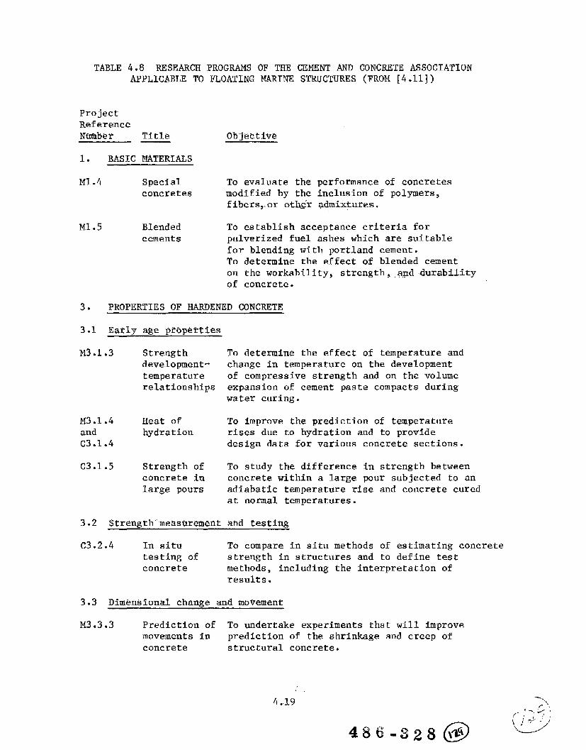
TABLE 4.8 RESEARCH PROGRAMS OF THE CEMENT AND CONCRETE ASSOCIATIONAPPLICABLE TO FLOATING MARINE STRUCTURES (FROM [4.11])
ProjectReferenceNtlmber Title
1. BASIC MATERTALS
M1.4 Special To evaluate the performance of concretesconcretes modified by the inclusion of polymers,
fibers,or othtiradmixtures.
M1.5 Blended To establish acceptance criteria forcements pulverized fuel ashes which are suitable
for blending wfth portland cement.To determine the effect of blended cementon the workability, strength, .agd durabilityof concrete.
3. PROPERTIES OF HARDENED CONCRETE
3.1 Early age prbpenles
M3.1.3 Strength To determine the effect of temperature anddevelopment- change in temperature on the developmenttemperature of compressive strength and on the volumerelationships expansion of cement paste compacts during
water curing.
M3.1.4 Heat of To improve the prediction of temperatureand hydration rises due to hydration and to provideC3.1.4 design data for various concrete sections.
C3.1.5 Strength of To study the difference in strength betweenconcrete in concrete within a large pour subjected to anlarge pours adiabatic temperature rise and concrete cured
at normal temperatures.
C3.2.4 In situ To compare in situ methods of estimating concretetesting of strength in structures and to define testconcrete methods, including the interpretation of
results.
3.3 Dimensional change and movement
M3.3.3 Prediction of To undertake experiments that will improvemovements in prediction of the shrinkage and creep ofconcrete structural concrete.
486-32$@
.- ..,.>F “-
:“;>-j;
U-L-’-’
4..19

TABLE 4.8 RESEARCH l?ROGMMS OF THE CEMENT AND CONCRETE ASSOCIATIONAPPLICABLE TO FLOATING MARINE STRUCTURES (FROM [4.11]) (Continued)
ProjectReferenceNumber Title Objective
4.
4.1
C4.1
5.
rJ5.1
6.
D6.3
D6.6
D6.8
CONSTRUCTION-METHODS
Formwork
.2 Fo1311w0rk To understand the mechanisms which determinepressures the maximum concrete pressure on formwork.
CODES, STANDARDS, “DESIGN METHODS-AND”MANAGEMENT
Probability To survey and evaluate current developmentsstudies in the field of probabilistic design.
BEHAVIOR OF CONCRETE ELEMENTS
Impact
Cracking intension
Temperaturegradients
D6.11 Tunnellinings
11. DURM31L1TY
M1l.1 Durabilityof concrete
Mll .2
D1l.5 Corrosion
To establish limits within which conventionalstatic design methods can be used for impactloading on structural members, initially tostudy rate of loading on failure modes ofbeams.
To improve our knowledge of cracking and henceto rationalize its treatment in design. Inparticular, to provide information on crackingin large tension members with relativelywidely spaced bars.
To determine the effect of temperaturegradients and to investigate the crackingmechanisms involved in concrete cylinders.
To develop design methods for reinforcementin precast elements, adjacent to the dryknuckle joints.
(i) To study the dependence of durab~lltyon strength or cement content.
(ii) To examine the durability of concretecontaining cement ground with grindingaids.
To improve understanding of the corrosion ofsteel in concrete and, in particular, of itsrelation to cracking.
4,20

In 1974 the IRO, together with the underwater technology divisionof the Royal Institution of Engineers and the Economic Affairs Ministry,set up the steering committee on problems associated with offshore
structures known as Stul?OC [4.17]. About 11 projects were conductedconcerning the design, construction, and installation of jacket–type andgravity structures. Table 4.9 lists two StuPOC studies that were directlyrelated to the use of concrete in the marine environment.
StuPOC proved the value of this type of research and led to thelaunching of the second program, Netherlands Marine Technological Research(MaTS). The MaTS programs , whose first phase began in 1978, gathersindustry support, both technical and financial. So far, the MaTS programhas initiated studies on 35 different subjects. The programs which dealwith concrete in the ocean are listed in Table 4.9.
Although the IRO gets cooperation from other organizations concernedwith concrete, welding, and materials , about 95 percent of the researchwork is performed at the TNO institutes in The Netherlands. flso involvedare such organizations as the Delft Soil Mechanics Laboratory, the DelftHydraulics Laboratory, and the Netherlands Ship Model Basin in Wageningen.
The MaTS programs are in various stages of completion, and the finalreports will be published by The Netherlands Industrial Council forOceanology. An increasing number of the reports will be available inthe English language.
4.5 Norway
4.5.1 Det Norske Veritas (DnV)
The rapid development ofto a variety of different designs.in the North Sea, DnV has served asfor 14.
offshore concrete structures has ledOf the 17 concrete gravity platformscertifying authority or as consultants
In the United Kingdom Sector, DnV, engaged as the certifyingauthority, has issued certificates of fitness (valid for five years) toseven of the ten platforms on behalf of the UK Department of Energy. Inthe Norwegian Sector, the detailed evaluation and control of the offshorestructures have been delegated by the Norwegian Petroleum Directorate(NDP), and DnV is active in this capacity. However, the formal approvalsare issued by NDP.
Det norske Veritas is active both as a certifying and researchorganization in fixed and floating concrete structures. References 2.1and 2.2 contain rules and guidelines for design, construction, and.—. .— ___classification. DnV is a participant in the UK Concrete in the Oceans
..—
Program described in Section 4.3.2 and in the Norwegian/German COSMAReffort discussed in Section 4.5.3. In addition, DnV conducts a number
of internally and externally sponsored confidential research projectswhich are briefly described in Table 4.10.
4.21

TABLE 4.9 PAST AND CURRENT NETHERLANDS MARINE TECHNOLOGICAL
Project No.
StuPOC–111-3
StuPOC-111–3–1
BK-1
BK–2
BK–3
BK–4
RESEARCH IN CONCRETE (FROM [4.16])
Descri~tion
StuPOC Projects
Fatigue of concreteTO obtain a better understanding of the behavior of plainconcrete in compression under varying repeated stresses,constant-amplitude tests and programmed-stress tests weredone to verify the Palmgren-Miner rule. Applicability of
this rule for concrete gives the possibility of makingreliable estimates of the lifetime of concrete loaded withirregularly varying compressive stresses.
Fatigue of concrete, safety considerationsThe main intention for the safety considerations associatedwith fatigue is to indicate a direction which theinvestigations should follow to set up a reliableprobabilistic calculation of fatigue. These considerationsare based on the experience and insight gained from theinvestigation of fatigue of concrete (StuPOC-111-3).
MATS Projects
Fatigue of concrete structuresTo obtain a better insight in the deterioration of reinforcedconcrete in a marine environment, preparations are madefor research into
- stationary and nonstationary random stresses undercompression
– stationary and nonstationary random stresses undertension and bending forces.
Inspection and monitoring methodsMethods will be investigated by which it will be possibleto detect cracks in concrete and corrosion or fracture ofsteel reinforcement bars at inaccessible parts of offshorestructures.
Repair and protection of concreteA state-of–the–art report on underwater repair and protectionof concrete will be prepared indicating those techniqueswhich merit further research and development.
Influence of oil on concreteBased on a literature review and interviews with industry,
a proposal will be prepared for further investigation intopossible harmful effects of oil and oil/seawater onreinforced concrete.
4.22
486-328 @
, “... ‘“”/.,.-< LJ ,,
“’,-.—-.<,

TABLE 4.9 PAST AND CURRENT NETHERLANDS MARINE TECHNOLOGICALRESEARCH IN CONCRETE (FROM [4.16]) (Contfd.)
BK-5 Influefice”of’temperature ‘rhangeson concreteAn inventory of available research in this field will beprepared. There is some question regarding the conclusionsof French and British research on the magnitude of observedcracks.
BK-6
BK-7
BK-8
ST-1
ST-2
ST-3
New materials for concreteA state-of-the-art report will indicate the applicability
of new materials t-oconcrete structures.
Cbtidrete in the deep k~a efivlrbfimentApplication of reinforced and prestressed concrete at depthsgreater than 100 m requires investigation of the behavio~of concrete at such depths. A proposal for further researchwill be prepared.
Stress-corrosion of prestressing steel WfresThere is insufficient knowledge on this phenomenon, and aproposal for further research will be prepared.
Dynarnic-behavtor of offshore stricturesBased on a review of available information, a proposalwill be prepared for further research into:
- Definition of actual loads on offshore structures- Relative importance of loads caused by different
phenomena- Influence of damping effects on the dynamic behavior
of offshore structures.
!%fdelities for’iletidfng’otithe bptimum cofiflgtiratfonof astrticttire’tifiderprwktermified CondltitmBased on existing configurations and their environmentalconditions, an optimization procedure for configurationsat future locations with knowo environmental conditionswill be developed.
Probabfli~tic safety analy~fs for off~h~r~ structuresDeveloping and testing of a probabilistic safety analysisprocedure for gravity and jacket structures, taking intoaccount wave loads, own weight and deck loading, andfoundation characteristics.
ST-4/5/6 Biickling”and tbllapse calttilatiorm on fldaring; fixed,andgravfty-:’gtrtictiirtsState-of-the-art reports will be prepared on buckling andcollapse research into steel and concrete shell structures.As a result, proposals for further research may be expected.
4.23 . ‘.,/=
“.&:

\ -. —
TABLE 4.9 PAST AND CURRENT NETHERLANDS MARINE TECHNOLOGICALRESEARCH IN CONCRETE (FR0M [4.16]) (cOnt’d.)
ST-18 Nondestrtictivefinspe~tfofi-Jbf‘offshore striicttire~Development of NDT techniques for inspection duringconstruction and monitoring of installed structures.
VM-2 Mathern~tl&al<Sttiulatidfi’methods’ for flbating ”strticturesThe various phenomena will be listed, and the possibilityof describing their effects in mathematical terms will beanalyzed. Treatment of these aspects in existing simulationtechniques will be reviewed, including restrictions.

TABLE 4.10 RESEARCH PROGRAMS AT DET NORSKE VERITASAPPLICABLE TO FLOATING MARINE STRUCTURES
TITLE :
OBJECTIVE :
TASKS :
APPLICATION:
STATUS :
REPORTS :
SPONSORS :
CONFIDENTIALITY :
TITLE :
OBJECTIVE:
APPLICATION:
STATUS :
REPORTS :
Develop a computer program (NLCON) for reinforcedconcrete based on the nonlinear behavior of the concretein service and ultimate limit conditions. The programwill be based on already existing nonlinear programsfor reinforced concrete available within DnV.
Theoretical evaluation, programming, testing, andreporting.
Offshore
Started in 1978 and planned to terminate In 1981. Usertsmanual for NLCON is written. At present an extensionof NLCON is being planned.
User’s manual for NLCON.
Det norske Veritas
No distribution without permission from the responsibledepartment at Det norske Veritas.
Shear Test”on CofieswtePlates
Analyze the effect of water pressure in cracks on theshear capacity of concrete.
The permanent high hydrostatic pressure acting on theoffshore concrete structures will force fluid intocracks as soon as they start to develop. Togetherwith combined loadings from moments, axial forces,and shear forces, the presence of high water pressurein cracks may significantly influence the ultimateshear capacity. Present designs do not adequatelyconsider this. The present experimental work willsupplement the current research work on ultimate shearcapacity in offshore concrete structures.
Test results are being reported.
Not yet published.
4.25
...-.——. . .—.—— ---

TABLE 4.10 RESEARCH PROGRAMS AT DET NORSKE VERITASAPPLICABLE TO FLOATING MARINE STRUCTURES
(FROM [4.18]) (Cent;d.)
SPONSORS : Det norske Veritas.
CONFIDENTIALITY : No distribution without permission from the responsibledepartment at DnV.
TITLE :
OBJECTIVE: Define relevant data on the behavior of reinforcedconcrete in the marine environment with respect tocorrosion, i.e.,
- define the need for protection and the criteria forworkmanship and design
- describe the material behavior of corrosion with respectto electrochemistry
obtain a basis for inspection and methods of recording.
TASKS : (1) Field experiments(2) Laboratory experiments(3) Field exposure
APPLICATION: Defining the serviceability requirements and thecorrosion hazards on offshore structures will resultin final recommendations and criteria for various methodsof protection systems. This will give a higher levelof confidence in the safety of the offshore structuresand reduce the maintenance cost.
STATUS : Seventy reinforced concrete specimens have been submergedin a fjord near Bergen, Norway. Precracks in thespecimens vary from O to 0.5 mm, with covers of 20 mmand 50 mm.
Measurements recorded after one year of exposure insea water indicate that the reinforced concrete specimensbecome nearly “passive,”’ possibly due to:
- precipitation of CaCo3 and Mg(OH)2 from the alkalineenvironment into the concrete
an organic layer covering the concrete surface
eventual end of hydration
4.26

TITLE :
OBJECTIVE:
TABLE 4.10 RESEARCH PROGRAMS AT DET NORSKE VERITASAPPLICABLE TO FLOATING MARINE STRUCTURES
(FROM [4.18]) (Conttd. )
TASKS :
Damagp”of Offshore’’Platfd~s’ ”-”:Afialysis-””and”Repair
The primary objective is to classify types of damageto offshore concrete and steel platforms. Establishment
of criteria concerning the necessity and quality ofrepair work is required to prevent progressive expansionof various types of damage. Further development ofuniform methods for a systematic analysis of varioustypes of damage and the study of the reliability ofpresent repair work is necessary. Repaired damage onpresent platforms will be followed up in addition tomodel testing of simulated damage and repair work.
(1) Study and pursue records of damage and repair onoffshore concrete and steel platforms. Structuresunder similar environment and loading conditions will
be examined so findings can be extrapolated to offshoreconditions.
(2) Develop methods for systematic and uniform analysisof present damage and associated consequences. in order
to classify damage and repair.
(3) Study present methods of repair of offshorestructures below the waterline.—.—,. ... .....——
(4) Test quality and reliability of alternative methods
of repair under simulated damage conditions on testmodels.
(5) Establish a system of classification forregistration of platform damage for future reference.
(6) Establish criteria for acceptable size and typeof damage and the resulting need for repair and control.
APPLICATION: Various types of damage have already occurred and moreare likely to happen in the future. To have requirementsfor reliable repair and control, it is necessary toestablish uniform methods of classification and analysesof damage. The choice of repairing damage may influencethe future safety of the platform and prevent unnecessarybreaks in production or inefficient methods of repair.
STATUS :
SPONSORS:
Due to start in 1979 and terminate at the end of 1981.
Royal Norwegian Council for Scientific and TechnicalResearch (NTNF) and Det norske Veritas.
4.27

TABLE 4.10 RESEARCH PROGRAMS AT DET NORSKE VERITASAPPLICABLE TO FLOATING MARINE STRUCTURES
TITLE :
OBJECTIVE :(i)
(ii)(iii)
TASKS :
1.
2.
3.
4.
5.
6.
7.
(FROM [4.18]) (Cent’d.)
T~Dacts ~fid”Collfsibns” Offshore
To obtain knowledge about:The probability of impacts and collisions between fixed
offshore structures and mobile vessels.The capacity of offshore structures against ship impacts.Design criteria for impact loads on steel andconcrete offshore structures.
Study of literature, with an overall survey of theavailable theory and experiments.
The probability of collision -Apply various statistical methods to obtain theprobability of collisions between an offshore structureand ship. The probability level will be related tovarious offshore structures, ships, offshore fieldlocations, relative velocities, and various impactmechanisms. The statistical distributions will berelated to existing data from the North Sea.
Energy absorption/deformability of ships -Classify various types of impact mechanisms relatedto damage and consequences. Establish the energyabsorption/deformation characteristics of the shipsmost likely to operate offshore. If necessary, performstatic/dynamic testing.
Impact capacity of concrete platforms -Theoretical investigation supported with model testingto obtain the capacity against impacts under serviceand ultimate conditions.
Impact capacity of steel platforms -Theoretical investigation supported with experimentalwork to establish the serviceability and ultimateconditions against impact loads.
Frequency of collisions and damage -A systematic recording of data from collisions anddamages in the North Sea.
Design criteria -Estabish recommendations and design criteria againstimpact loads on offshore structures including variousmethods of protections.
4.28-—..

TM!LE 4.10 RESEARCH PROGRAMS AT DET NORSKE VERITASAPPLICABLE TO FLOATING MARINE STRUCTURES
STATUS :
REPORTS : 1.
2.
3.
4*
5.
(FROM [4.18]) (Cent’d.)
A study of offshore fender systems investigated thelikelihood and nature of offshore collisions, theirprobability, and fendering efficiency. The work ispresented in a report which gives recommendations forthe protection of offshore structures, covering bothdesign criteria and possible fender systems. See (1)below.
Alternative statistical methods of obtaining reliableprobabilities for offshore collisions between platform/ship have been studied. For future work, a simulationtechnique will be preferred. See (2) below.
A pilot impact test on concrete cylinders has beenperformed, giving new and useful information for thebenefit of further studies of the physical phenomenaoccurring during impact. Prior to the impact tests,the models had been used in another project at DnV,where they were tested to failure under hydrostaticpressure. See (,3)below.
An antilysis of the structural ship behavior underpossible collisions with various types of offshoreinstallations in the North Sea has been reported,including also the effect of eccentric impact againsta ship’s side and its superstructure. See (4) below.
Offshore Fendersystems.Collisions and Fendering Offshore, DnV Report No. 77-156
Impacts and Collisions Offshore.Simulation Applied to Analysis of the Probability ofCollision Between Ships and Offshore Structures.Progress Report No. 1, DnV Report No. 78-037.
Impacts and Collisions Offshore.Pilot Tests with Pendulum Impacts on Fendered/UnfenderedConcrete Cylinders.
Progress Report No. 2. DnV Report No. 7-106.
Impacts and Collisions Offshore.Impact and Energy Absorption of Ships (only inNorwegian).Progress Report No. 4, DnV Report No. 78-433.
Impacts and Collisions Offshore.Analysis of Penetration of Hulls.Progress Report No. 4, DnV Report No. 78-433.
4.29

TABLE 4.10 RESEARCH PROGRAMS AT DET NORSKE VERITASAPPLICABLE TO FLOATING MARINE STRUCTURES
6.
7.
SPONSORS :
CONFIDENTIALITY :
TITLE :
OBJECTIVE :
TASK : (1)
(2)
(3)
(4)
(5)
APPLICATIONS:
STATUS :
REPORTS:
SPONSORS:
CONFIDENTI~ITY :
(FROM [4.18]) (Contrd.)
Impacts and Collisions Offshore.Computer Simulation Analysis of the Collision ProbabilityOffshore.Progress Report No. 5, DnV Report No. 78-624.
Impacts and Collisions Offshore.Computer Simulation Study of the Collision ProbabilityBetween Tanker/Platform.Progress Report No. 6, DnV Report No. 79-0192
Royal Norwegian Council for Scientific and TechnicalResearch (NTNF) and Det norske Veritas.
No distribution without permission from the responsibledepartment at Det norske Veritas.
RelfabilitV --Offshore Structures
To assess available tools and data in order to recommendprocedures for calibration of the rules for offshoreconcrete and steel structures.
Establishment of a data bank on accidents and failuresof offshore structures.
A study of failure modes of offshore structures.
Development of a computer program to calculatethereliability of a system with multiple variables.
Calibration of the performance of a limited number offailure modes in order to evaluate the proposed process.Studies of the most suitable rule format for aprobabilistic base.
Summary and recommendations.
Development of codes and rules for offshore concreteand steel structures.
Completed in 1979.
Five reports have been completed and further reportsare in progress.
Part of the project sponsored by the Norwegian ScientificResearch Council.
Unrestricted distribution.
4&30

4.5.2 Norwegian Institute of Technology (NTH)/The Foundation ofScientific and Industrial Research (SINTEF)
4.5.2.1 Norwegian Institute of Technology
Over the years, the technical divisions at NTH havebeen active in research dealing with both steel and concrete structures.Much of the involvement is naturally directed offshore because of Norwaytsinvolvement in the North Sea oil exploration and production. Both theinternational conference on the Behavior of Offshore Structures (BOSS
’76) [4.19].in 1S76 and th”esyrnposiufi’”Cofi&ete.Strudtur@s [4,20~.in-—...—. ..-—..1978were held at NTH. ““
-——.-.., ,---- ..-—-—..—----- _____–-’ -—-
The Division of Structural Mechanics at NTH is involvedin the development of the theory and computer codes for nonlinear analysisof structures-including concrete. Examples of such published research
::--a-~~Tgivenin references 4.21 – 4.24..-,.—-.-. -— .———— -.-_ —.
A joint effort is being conducted by Det norske Veritasand NTH to develop a finite element code called FENRIS (Finite Elementof Nonlinear Reinforced Integrated Structures), which will supplementthe DnV program SESAM. FENRTS will include both nonlinearities in geometryand material constitutive relationships. It will also consider staticand dynamic loading and response.
NTH and SINTEF already have several programs for thelinear and nonlinear analysis of concrete structures such as the NorthSea platforms. Two codes CYLSHELL and CONSYM3 are briefly described below:
CYLSHELL [4.25] – A program for the static analysisof structures composed of an arbitrary system of cylindrical shells. Theshells are assumed to be simply supported along the curved edges. Alongthe straight edge , which may have arbitrary boundary conditions, aparticular shell may be connected to other shells, directly or via anedge beam.
The program can handle several kinds of loading:gravity load, loads parallel to local shell axes, temperature loads, andloads arising from prestressing. The loads may vary both in the axialand circumferential directions (described by Fourier expansions).
CONSYM3 [4.26] – For nonlinear analysis of axisymmetricconcrete structures loaded axisymmetrically, structures may be modeledby both shell elements and solid elements. In the coupling of the twoelement types, the master-slave technique is used. Both cracking of theconcrete and nonlinear stress-strain relations are included. Creep ofconcrete can also be taken into account. Prestressing is included andmay be analyzed in several steps. The load history can be simulated byusing load increments and independent load vectors.
“4*31

NTH is not only active in structural analysis, butalso conducts experimental programs in concrete material properties,corrosion of imbedded steels. and field surveys, [4.27-4.29]. Reference4.27 is particularly Interesting because it gives the results of a 5–year program to survey and report the durability of reinforced concretewharves in Norwegian waters. Information on some 716 structures, somedating to 1910, was collected; 429 of these were slender-pillar quays.One–hundred seventy structures were selected for direct inspection. Theobjectives and main results are quoted below from reference 4.27:
In lorwegian harbou~s, particularly in thoze of middle size,a zteadily inewusing popo~tion of d-za~vezand pier~ dur<ngth~ la~t half centu~y have bean con~trueted as eo-called“sbzde~-pilla~trreinfowed compete gtwctuve~. Tlrb W@due to the praetiieeof concreting such pillars under watievby the zpeeial t?emie method int~odueed in Norway about1310 by MF. Auguzt Gundevwn of the firm A/S Hdyer-ELlefsen,06-LO. Combined with a ~imple sy~tem of p~ejea,b~ieatingtheuooden form. on dzorieand placing them uith the reinforeemaata~ complete units on foutitions p~epaved in the zea bed,the m~thod made such ~truetuw~ le~~ costly than mo~t othe~type~ of quays fop wlutivaly heavy t~affie, provided thegoil conditions Mew not too unfavouvable. A p~tieularadvantage, especially in the older dayz, and al~o duringthe reconstwction after 1945, wuE that heavy equipment,like la~ga hzrge~, craneg and pile drivers could, if notpeadily avai~abla, be di~penzed uith.
Nany engineers zwre doubtful about kha pouring of concreteunder water. Although apparently sati~faetory performanceof mi~tiing struetums created inewasing confidence, stillone did not know uhat the real-htie economic life =pectancyfor these quay strueturez ~ould be.
The Concrete Committee of the florzmgian Society ofP?ofessionul Engineww, appointed in 1926, p?<matily toinvestigate the eoncwte in hm~ and ~imila~ ~tm.mhwez,therefore aftav 1930 extad~d itz IWrk to ma~itima structu~as,ineludi~ algo some slander-pi~la~wharvez and piaw. !4P ●
K~isten FviiG, membep of the p~esent committee, mz theseereta?y of the comm-ittee of 1926, uho conducted theinv~~tigation and wrote the ~epo@.* Due to lack of fundsthe scope of the investigation had to b vather restricted.Only a couple of stn..ctumz were inspected undw watw.l’hegeneral conclusions stated on pzge 30 of the r~portMare neve?the~ese very interesting. All concrete uhiekhad been permanently submerged kept ueZZ. Damage oeeur~p?imarily in the tidal ,zone,~vtieula~ly on lean eoncwta
‘Den flomke Ing&ni~ owni?ags Betongkomite’,Meddelelse HP. 3: “Batong i Sj@ann, t’Oslo 1936.
4.32
486-3z8(@
~.‘,,
,,,.,,’ ,
. . . . . ‘j‘,,,‘cl’

and at eon~twetion joints. Leaving the uooden form~ inplace on pillarg a~ Mall az on mor~ mussy strue-turw mzfound to be advantageous. The bwm and stab type~ of quuydeekg in mung ca~e~ dzoued damage due to rushing ofreinfo~cement, attributed to the concr~te eove~ing overthe ztaeZ being too shallou. The u~e of mhmtural steelframe ag reinforcement and at the sam time a~ zupport fovthe form had proved -huztW%able.
Altogether the investigation in the early 1930’E gave thezlende~-pills? ~einforeed eonc~ete quay~ only a ~omeuhatqualified bi~l of health, except as Pegavds the permanentlyGubmePgad part of -thepillaw. Ieoe~theless the use ofGuch st?ueturez continued to inerwase, as may be sewz fromFig. 16 of the ~epo~t~ ofMr. Gi~rv, attached heveto.
outeida of flOWUy, houever, thig type of quay stmetu?ez[m%] has hmdly been ueed at all, and the method ofconcreting umal in NoPuzy ~eemz to be vieved with littleconfidence in other eountr+es, as fa~ as it i~ beingeonzidered at all.
Alv’eadyin the middle of the 1950’s the ~tate of affaimdezeribed above made flo~vegianenginee?z feel the need ofa na.?investigation of ou~ Pm+ieulap type of quay ztpuetupes.If ue had fop some 50 yearn bean using this type, it zeemedto be high time that Me aseeptain beyond doubt @hat theresult of such p?aetiee hud been. The Io?die initiativementioned above p?ovided the incitement to get on tiiththejob.
Main Results of the Investigation
The autho~ of the p~ezent book haz, in the opinion of theCommittee, adequately and co??eetly stated the Pesults ofhi~ investigation and the eonclusiong they ju~tify.
fleverthele~z,the Committee feel~ it expedient to emphasizeb?iefly in this PepoPt ~ome points which seem to be of specialpvaetieal impo?tanee.
l%e purpose of the investigationms to detect and describeany &zmage inflicted until nou on floruegian PeinfoPeedcone~ete uharves and pievs. Coneequantly the ~epo?t inthis book must dwell ~omeuhati on such damage as has beenfound. ~i~ should not, hotieve?,obscu~e the moGtiimpo~tantove?all ?ew~t of the investigation,mmely that on the@hole the reinforced concrete uhar=-vesand piem have ztoodthe te~t of time ~ema~kably uall, a~ zeen from the diagvamsof Fig. 170 a and b.
‘~See refe~g”nge 4.27.. .
.*,/ (, ,;’,,+’..’ _
:>
4.33
Rema~kabZe i~ a~~o [ziel the agreement between the eonclu~ion~dram in the 1930’s, wnuned up above, and those nm awiv~dat: BelozJLou tide level thew is vwy little damage. Inthe tidal zone d.wte~iorationtakez place, at a mte tihichis highly dependent on the quality of the concrete. Leavingthe forms in p2aee on pilla~s and mllz gives effectivep~oteetion. Cor~osion of zte~l in the ztructu~e above highmzte~ level Ls a seriouz cuuse of hmage, but even the oldestand the mo~t seriously attaelwd stmwtuwz ar~ still inSwviee, partly after Gome repaivs.
T@ fact that the ove~all picture of the structures builtbefore 1930 changed so little during the thirty-odd yea~sfrom the firgt to the second -bzvectigat-ionindieata thateven where ~erious deterioration occurs, the p~oce~z appear~to be quite Glou. me same eonelu~ion is indicated by theappa?etitlymall effect ofFig. 170 a and b.*
The results of the pvasentsett2e any doubt about the
age of structures, a~ Geen from
investigation dzould definitelyr~liability of tremie poured
underuutev concrete in slender pillarg. Most pillar~ (87%)were in good condition independently of age. Such dumageaz ZJIGfound, YKUSelaa~ly attributable to deviation~ f?omthe UQLL knozm and simple mle~ of practice. Such deviationsunfortunately oecuYJin conc~eting, above as uell a~ belou~ater. In the Zatte? ca~e, the rulez ape in fact moreeZeaFcut and simpler to follou than -in many cazez ofconcreting above mtier.
The deplorable fact that even in 1960-65 ~e?%oug defectsin the unde~-uater pillam of one st~uetu~e ua~ caused byfault~ in concreting, probably due to overconfidence inpersonal ~udgement, emphasizes the nece~zity of ~t~ictlyfollouing the accepted rulez. The autho~’g recommendationsshould be carefully noted.
As to the durability of pillars in the tidal zone, theimpo~tance of u~ing high quality, f~o~t resistant eone~ete~hould be emph.a~ized. Still, the precaution of leavingpressu~e imp~agnated form~ in place should be taken, asadditional cost <6 very .smdl.
The mozt vulnerable pa~t of the usual quay ~tructuredefinitely is the pwt above high mte~, e~pecially thedeck beams and slabs. Although the proee~g of breakingdom the b~a?ing capacity of the deckz s~ems to be very6LoM, az stated above, degign and con~trwction dzould aimat counte~acting such development to the greatezt possibleextent. The results of -H-w investigation and the di~cuz~ionthereof indicate ce%ain pmcuutionz uhieh may tiellbe brieflyenumerated here:
*Figurw 170a and b refer to figu~e~ found in reference 4..27.
4.34
4$6-328 @
.,,.:.’ ‘,/
‘2!!’

a.
b.
e.
d.
@.
use of high quality eoncret~ with very lowpermeability and high frozt rwi~tanee.Adequate and uniform thieknes~ of the coner~teeovm+zg the -cement.Leaving as much elearanc~ az p~actical betzwenthe bottom of the beum~ and z~abz ad the h-ighwutm level.>ooiding adequate horizontal Gupport to preventerackz opening due to impact of ship~.Avoid Geriouz ov~vloading, for the Game wagona~ d.
tie results do not give baz-h for a definite choice betweenbeam and ~lab VQFWS flat slab decks. tie &ta certainlyindicate mow extawive and move ~e~iou~ damage on beam~than on ~lab~. AIGo the pwcuutionz enume~ated above de~a, b and c, can all ~omewhat more easily be taken care ofwith a flat zlab deck, than with one of beam and ~lab.fii~ i~ particularly trwe aG vaga~d~ point e, which iz animportant one.
In practice the ehoiee will depend on dzat oalue Mill beplaced on a longer economic life acpectancg a~ again~t aminor ~aving in firgtico~t.
RepaiFz of dzmage due to corrozion have been made in manyea~es, but durable msult~ have not been attained. Repair~~hould be made under careful conside~ation not only of~t~uctural, but also of electro~ytiealand chemical rwlationg,as discus~ad by the author.
4.5.2.2 The Foundation of Scientific and Industrial Researchat the Norwegian Institute of Technology
SINTEF is a nonprofit organization performing researchunder contract to corporations, industrial associations, public service
agenci~sy gover~ent departments, and other clients. SINTEF was established
in 1950 as a free foundation by the action of the Norwegian Institute ofTechnology (NTH) in close cooperation with interested parties withinNorwegian industry.
The Cement and Concrete Research Institute (FCB) isan affiliated institute in SINTEF and conducts a variety of programs dealingwith concrete. Examples of research concerned with marinestructures include:
o Quality characteristics of cement
o Impact loads on concrete shells
o Concrete exposed to high water pressure
o Characterization of structure in hardened
4.35
concrete
concrete

o Evaluation and control of steel corrosion in concrete
o Sulphate resistance of cement
o Effects of temperature.
FCB is engaged in a program called “Concrete Shipsin Norway.’* It is a survey of four concrete ships which are 35-60 yearsold . The scope of work includes an evaluation of the concrete and a reviewof the designs. This study is jointly funded by the Norwegian Councilfor Scientific and Industrial Research (NTFT) and private organizations.As such, any results are presently confidential. However, some info~ationconcerning the ships surveyed is reported below:
Vessel No. 1: DredgerBuilt: 1945Service: Still operationalConstruction: Ordinary reinforced concrete (Outer shell 90
mm thick, inner walls 60 - 70 mm thick, deck100 mm thick)
Vessel No. 2: Coal and Sand BargeSize: 10 m wide, 56 m long, 6 m deep
Built: 1918 in EnglandService: Stranded in Norway in 1942Construction: Prefabricated panels 60 mm thick
Vessel No. 3: Description unknownSize: 4.5 m wide, 16 m long, 2.5 m deep
Built: About 1919Service: 40 or 50 yearsConstruction: Used sprayed concrete and constructed as a wooden
vessel with double curvatureStatus: Damaged by ice, and reinforcements in damaged area
are corroded. Owner would like to repair, but methodof repair is uncertain.
Vessel No. 4: Description unknownBuilt: During World War IService: 15 or 20 years
Construction: Similar to Vessel No. 3Status: Particular interest in this vessel because it has been
subjected to Arctic conditions for the past 35 or 40years.
CEB is also a participant in the Norwegian/GermanCOSFMR Program, which is discussed in the next section.
4.5.3 Norwegian/German COSMAR Program
The Norwegian/German COSMAR Program (Concrete Structures forMarine Prediction, Storage and Transportation of Hydrocarbons) is a large,international research effort dealing with concrete structures in themarine environment. The four projects include:
486-328 @
\\{ >,”:‘1...“ /-
!<J,
‘<--‘“”
4.36

(1) Investigation of offshore concrete structures withrespect to static strength.
(2) Investigation of offshore concrete structures withrespect to fatigue strength.
(3) Development of concrete structures for storage andtransportation of LNG and oil, including thermaleffects.
(4) Concrete offshore structures subjected to ice andArctic conditions.
The participants originally consisted of West German and Norwegian groupswhich included:
German Group Norwegian Group
Dyckerhoff and Widmann, Munich Det norske Veritas, Oslo13ilfin&er und 13erger,Mannheim Cement and ConcreteHochtief, Essen - “Philipp Holzmann, HamburgMeerestechnik und Seebau,Hamburgische SchiffbauVersuchsanstalt, Hamburg
Research Institute, TrondheimNorsk Hydro, Oslo
Hamburg Norwegian Contractors, OsloDen Norske Stats, StavangerExxon Production Research
Company, HoustonMobil Research and
Development Corporation,Dallas
Shell International Petroleum,The Hague, Netherlands
Later participants include the United Kingdom Department ofEnergy and Mitsui in Japan. COSMAR is also supported by the EuropeanCommunities, the West German Bundesministerium fur Forschung undTechnologies, and the Royal Norwegian Council for Scientific and IndustrialResearch.
Table 4.11 gives the objectives and status of each project.The COSMAR program was scheduled to end at the middle of 1981, with theresults being confidential to the program participants.
4.6 Treat Island, Maine, Concrete Exposure Station
4.6.1 Description of the Test Facility
Since the placement of the first specimens in 1936, the TreatIsland, Maine, exposure station has been used for studies on the naturalweathering of concrete and concreting materials. The severe weatheringstation presently consists of a wooden exposure rack 37 m x 12 m (120 ftx 40 ft) and a portion of beach 61 m (200 ft) long. The station is exposedto a twice daily 5.5–m (18–ft) tide and to severe winters. Specimensare installed at mean–tide elevation, and the alternate conditions ofimmersion of the specimens in sea water, then exposure to cold air, provide
4.37
486-32$@
‘...

TABLE 4.11 NORWEGIAN/GERMAN COSMAR PROGRAM(FROM [4.18])
PROJECT NO: 1
TITLE : Investigation of Offshore Concrete Structures WithRespect to Static Strength
PROJECT LEADER: Cement and Concrete Research Institute, Trondheirn
OBJECTIVE: To obtain knowledge required to determine the ultimateload–carrying capacity of complex reinforced andprestressed concrete structures composed of shells,plates, frames, etc., for load combinations typicalfor offshore structures. Further, to develop procedureswhich can be used for design of more demanding structuresthan those being designed today.
STATUS : A pilot test on four concrete shell models has beenperformed by DnV, investigating the intersection of adome and cylinder, implosion due to excessive hoopcompressive stresses in the cylinder walls, and thereliability of tests carried out at the fairly smallscale of approximately 1:10. The project plans toconcentrate its effect on the concrete strengths withrespect to shear, materials, and implosion.
PROJECT NO.: 2
TITLE : Investigation of Offshore Concrete Structures withRespect to Fatigue Strength
PROJECT LEADER: Det norske Veritas, Oslo
OBJECTIVE: To obtain improved information on the fatigue strengthof concrete under hydrostatic pressure, in order topromote development of reinforced concrete structuresexposed to a marine environment. The fatigue compressivestrength of reinforced concrete will be investigated,including the effects of external hydrostatic waterpressure, frequency of loading, different straingradients, cumulative damage, and cracked or untrackedsections.
STATUS : Pilot testing of 14 reinforced concrete specimens wasplanned and executed at DnV in the period 1975-1976.
4.38

TABLE 4.11 NOIWEGIAN/GERMAN COSMAR PROGRAM
PROJECT NO:
TITLE :
PROJECT LEADER:
OBJECTIVE :
STATUS :
PROJECT NO.:
TITLE :
PROJECT LEADER:
OBJECTIVE :
STATUS :
(FROM [4.18]) (Control)
3
Dyckerhoff und Widmann, Munich
To develop and construct reinforced and prestressedconcrete structures in the offshore area for theproduction, storage and transportation of LNG and oil,detailed knowledge of the characteristics of concreteand reinforcement under the effect of LNG and oil isnecessary. It may well be necessary to develop specialconcretes with the required properties, consideringthe process of manufacture and the final product subjectto offshore environment and its particular use. Inaddition, it will include a study of thermal structuraleffects. The influence of differences in temperatureand the resulting stresses and forces are of specialinterest.
Planned to terminate by the middle of 1981.
Bilfinger und Berger, Mannheim
Study the external load developed by floating ice onconcrete structures and the surface behavior of concreteinteracting with ice (abrasion and durability) in orderto arrive at new proposals for offshore structuressuitable for the production, storage, and transportationof oil and gas in Arctic waters. Feasible concretestructures will be selected for intensive theoreticaland experimental investigation of forces from driftingplate ice, pack ice, and ridges.
Planned to terminate by the middle of 1981.
4.39

numerous cycles of freezing and thawing of the concrete during the winter.During an average winter, the specimens are subjected to over 100 cyclesof freezing and thawing [4.30].
All exposed specimens are inspected visually by the residentcontractor each week during the period that freezing and thawing cyclesoccur, usually October through March. The condition of each specimen isrecorded on an inspection form which is forwarded to the StructuresLaboratory, U.S. Army Corps of Engineers Waterways Experiment Station(WES), along with the time-temperature history for that week. Duringthe summer of each year, an inspection and testing team from the WES visitsthe exposure station for the purpose of performing the annual inspectionand testing of all specimens by visual and other nondestructive methods.During this annual visit, photographs are taken of all programs in progress,with special emphasis on programs of particular interest at the time andany specimens exhibiting significant or inordinate deterioration [4.30].
In addition to visual observation, for those specimens whoseshape, size,and condition permit, the resonant frequency of the test itemsis determined. From this testing, the dynamic Young’s modulus of elasticityis determined and used as a measure of the deterioration of the specimen.The specimens are also subjected to pulse velocity tests which can berelated to the dynamic Young! s modulus of elasticity. Specimens areregarded as having failed when they separate into pieces, when the percentYoungts modulus relative to the original value is 50 or less, or whendeterioration has progressed to such a point that reliable determinationof fundamental frequency and pulse velocity cannot be obtained. Specimensthat have been broken in handling are so listed and are not classifiedas “failed” [4.30].
4.6.2 Past Research
Specimens of various sizes and shapes have been used from timeto time in the outdoor exposure tests. There have been spheres, cylinders,cubes, prisms, and beams varying in weight between 2 and 454 kg (5 and1000 lb). Some 600, 89 x 114 x 406 mm (3.5 x 4.5 x 16 in.) concrete beamswith aggregate sizes up to 19 mm (0.75 in.) have been exposed and tested.A composite of about 1450, 152 x 152 x 762 mm (6 x 6 x 30 in.), 152 x152 x 914 mm (6 x 6 x 36 in.) , and 152 x 152 x 1219 mm (6 x 6 x 48 in.)prisms with aggregate sizes up to 38 mm (1.5 in.) have been exposed. Some610-mm (24-in.) cubes representing concrete mixtures, containing 152-mm(6-in.) maximum size aggregate, have been exposed. However, in 1963 itwas decided that specimens for outdoor exposure of mass concrete mixtureswould be 457 mm (18 in.) in height and depth, and 914 mm (36 in.) in length.The 457 x 457 x 914 mm (18 x 18 x 36 in.) prism was selected instead ofa 610-mm (24-in.) cube because it (a) afforded a longer path length forpulse velocity readings, (b) contained less concrete and therefore weighedless, and (c) was more amenable to tests for fundamental transversefrequency. In 1968, with the 457 x 457 x 914 mm (18 x 18 x 36 in.) prismsas the standard outdoor exposure specimen and with enough exposure rackspace available for the proper installation of a large number of prismson their nodal points, large mass concrete specimens were tested for bothfundamental flexural frequency and pulse velocity on a regular basis forthe first time at Treat Island, Maine [4.30].
4.40~,,/,,./-
% “-
0“ /“L__-—,.
4$6.3~8 1=
Exposure data are updated annually, giving Corps of EngineerEngineering , Construction, and Operations Divisions information on therelative ability of various concretes and concreting materials to withstandweathering. Re~orts describe the exposure stations, test methods used,the specimens, and list test results to date. The results of variousinvestigations which include severe weathering durability and performancehave been reported over the years. The analysis of data collected overthe years on selected research programs has been initiated in preparationfor reporting significant developments related to long-term exposure ofconcrete to severe weathering.
4.6.3 Study of Reinforced Beams at Treat Island
A study was begun in 1950 to determine the effects of severenatural weathering .o~stressed, reinforced concrete beams of variouscompositions and degrees of stress. The objective of the study was toobtain information on the long-term weathering of air-entrained and non-air-entrained concrete beams containing steels of different compositions,types of deformation, and different levels of stress.
A series of 82 beams was fabricated. These beams contained anumber of variables that might affect the durability of the concrete andthe steel used as reinforcement. Eighteen of the 82 beams were made withair–entrained concrete; the rest were made from a similar mixture withoutair entrainment to evaluate the desirability of air entrainment in severeenvironments. Thirty-nine percent of the beams were cast with 50–mm coverover the reinforcement, while the remaining beams had 19-mm cover toevaluate depth of cover. The reinforcing steel in the 82 beams conformedto ASTM Designation A 16-50T for “Rail-Steel Bars for ConcreteReinforcement ,“ or to Designation A 15-50T for “’Billet-Steel Bars forConcrete Reinforcement,” intermediate grade. The billet-steel barsconformed to ASTM Designation A 305–50T for “Minimum Requirements forthe Deformations of Deformed Steel Bars for Concrete Reinforcement.” Someof the rail-steel bars had deformations conforming to ASTM Designation A305–50T, and the others had old-style deformations that did not meet theserequirements. The different types of steel and types of bar deformationswere used to evaluate the resistance to deterioration of rail steel versusbillet steel and to see if old-style deformations or ASTM Designation A305 type deformations provided better pullout resistance. Thirty-threepercent of the beams were cast in an inverted position with their steelreinforcement in the top of the form, and the rest were cast in the uprightposition with the steel in the bottom of the forms. This was clone to
determine if the steel cast in the bottom of the beam would weather betterthan steel cast in the top, due to greater amounts of cement segregationat the bottom of the beam during casting. AH the beams, with the exceptionof the control beams, were loaded to put the tensile steel under stress.Beams requiring the same amount of load were yoked together in three–point flexural loading. The beams were loaded such that the various levelsof stress in the steel were O, 138, 207, 276, and 345 MPa [4.31].
The beams were placed on the beach at the natural weatheringexposure station on the south side of Treat Island, where they weresubjected to twice-daily tidal cycles and, during the winter months, tocycles of freezing and thawing. Annual inspections were performed during
486-3%28@
..-.,.,, ,-
,“ ,,, ,
,..
., .-— — /“
4.41

the exposure period and the results evaluated by a team of inspectorsrating the degree of deterioration. Maximum crack widths were measuredeach year from 1956 to 1975, when the exposure period was concluded.
Sixty of the 82 beams in this series were nonair-entrainedbeams. Since all of these beams deteriorated to a point of total failurewithin five years after initiation of testing, some of the variables wereeliminated because of failure of the specimens and lack of parametersfor comparison. The nonair–entrained beams contained all the billet-steel reinforcing bars, all the bars that were protected by 50 mm of cover,and all the reinforcing bars that had old–style deformations; consequently,all these variables were lost when the nonair-entrainecl beams failed.The variables remaining subsequent to January 1956 which could be comparedwere the degree of stress in the reinforcing steel, the amount of corrosionto the bar, and the effect of casting the reinforcement in the top orbottom of the beam [4.31].
At the conclusion of the exposure period in December 1975, 13of the 18 air–entrained beams were still in testable conditions. Elevenof these 13 beams were returned to the WES for structural testing andautopsy to evaluate the condition of the beams after 25 years of exposure.A typical beam as it was received in the laboratory is shown in Figure4.1. Seven of the 11 beams were tested to failure in three–point flexuralloading. All the beams failed in diagonal tension, with six of the failuresinitiated by pullout of the reinforcement from the concrete at the endexperiencing the diagonal tension failure. The results of the testingare given in Table.4.12. No definite relationship can be drawn from thedata with respect to ultimate moment and stress level. However, it canbe stated that the ultimate moments were not reduced below design levelsover the 25-year period due to level of stress, corrosion of thereinforcement, or loss of bond length from spalling except in the controlbeam [4.31].
An additional parameter was added to the evaluation of theexposure tests. This was the relation of crack width to the amount ofcorrosion on the steel. Also, the loss of cross–sectional areas of steeland chloride content determination tests were added to the testing program.As a general remark, the steel beneath the 19-mm cover was not heavilyrusted. There were areas that did receive corrosion where the concretecover was still intact, such as the tips of the reinforcing bars. But onthe whole, areas where the bars were not directly exposed to oxygen andsea water remained only lightly rusted. Where the concrete cover hadspalled, the steel was heavily rusted from direct exposure to the harshenvironment [4.31].
The data gathered by the teams of observers on the measurementsof crack widths over the period 1957 through 1975 indicate an increasein crack width with respect to both length of time under load and levelof stress applied to the reinforcement. It was observed that there wasmore corrosion on the bars at the higher stress levels. This was due tothe larger crack widths and the greater exposure to oxygen and sea water.Also, the results of the chloride content tests revealed concentrationsof chlorides ranging from 0.12 to 0.70 percent by weight of concrete sample,a chloride concentration high enough to severely reduce the passivating
4.42

TO* w oCAM
_, ,, __=, . ........._.5. S==---x= . . . . ..—-.. . .DOTTOIJ OF ecu
1--—seAwA.D i*OTTDW 0!= BEAM
,=—==L ..={ I
ITOPw w.”
SEAM 4
STEEL STRESS, 20,000 PSI
c==.===.:==..:--;-.,,,,,,,,.:,=.=,--,-:=--.---=,,,,,,,,,,,,:,,,mOTTOM OF WAU
1No.5
SEAW,W1. AP40M
No. mSO? ’m” w B<&M
I ~ 1,0. OF 8EM
SEAM 5
STEEL STRESS, 30,000 PSI
GRAPHIC REPRESENTATIONOF CRACKING AND
CORROSIONBEAMS 4 AND 5
FIGURE 4.1 GRAPHIC REPRESENTATION OF CRACKING AND CORROSION--~EMfs 4 AND 5 (FROM [4.31])
TAELE 4.12 ULTIMATE LOAD PROPERTIES OF BEAMS TESTED IN FLEXURE(FROM [4.31])
Moment Design RatioStress Failure Midspan Developedat
BeamUltimate M:Actual
Level, Stress Load, Deflection,UltimateLoad,No.
MomentNFa Position kN m N-m M;Design
—_ N“m2 138 Top 177 11.2 63,696 58,748 1-084
4 138 Bottom 169 13.1 60,795 58,74a S.0355 207 Top 154 20.1 55,521 45,664 1.216
7 207 Bottom 127 20.3 45,759 45,664 1.002
8 207 Bottom 168 12.4 60,469 45,664 1.32412 216 Bottom 150 40.8 53,989 30,791 1.753
18 Unstressed Bottom 137 6.1 49,270 58,748 0.839
4.43

coating on the reinforcing steel. However, no relationship between stresslevel and loss of cross-sectional area due to corrosion could beestablished. This was because the control beam , under no steel stress,had a cross-sectional area reduction of 33 percent, which was the secondlargest reduct:on observed. With respect to stress level and corrosionto the steel, it appears that they are not related except through thefact that the higher stress levels produced larger crack widths, whichallowed greater influx of the corrosive environment [4.31].
4.6.4 Current R~searth at Tr@at Island
There are 36 active programs concerned with natural weatheringat Treat Island. They include areas of investigation such as prestressedconcrete, fiber concrete, polymer concrete, sulfur-infiltrated concrete,and superplasticizers. Specimens currently installed at Treat Islandinclude those from the U.S. Water and Power Resources Service; the CanadianDepartment of Energy, Mines, and Resources; the U.S. Corps of Engineers
Waterways Experiment Station; and many other civil engineering projects
[4.6].,,..,,,,
Many Corps offices are using some of the more exotic concretessuch as fiber-reinforced concrete without adequate knowledge of theproperties, especially as they affect quality in hydraulic structures.Investigations pertaining to strength, durability, erosion and cavitationresistance, corrosion, and long-time durability need to be undertaken.In January 1975, 30 concrete beams (89 by 114 by 406 mm) which formed apart of the Civil Engineering Research Laboratory (CERL) Fibrous ConcreteProgram were installed at half-tfde elevation on the exposure rack atTreat Island, Maine, to determine the effects of the sea water and thefreezing and thawing action on the flexural strength and other propertiesof various fiber concretes. Half the beams were cracked prior to testing.These beams were exposed until July 1976, at which time 20 beams werereturned to CERL for laboratory tests. The remaining 10 beams are stillunder exposure. Under a second program initiated in July 1975, 50 concretebeams, a part of the WES Fibrous Concrete Program, were installed on theexposure rack at Treat Island. The number and types of beams exposedare: twelve, 152 by 152 by 762 mm; twenty-one, 152 “by152 by 914 mm;and seventeen, 229 by 229 by 1143 mm. The 229- by 229- by 1143-mm beamsare yoked and stressed by three-point loadings to working loads of 35percent of ultimate. Exposure of these beams is continuing. They areinspected and tested each year, and the loads are checked and adjustedif necessary. So far, sufficient deterioration has not occurred EO drawdefinite conclusions ~4~6.].fl,
.__._”..——,”..—.
Polymers are being used in concrete in the field for bothrestoration and new construction. Little is known, however, about thecharacteristics of the polymer-concrete composites and the proper mannerin which they are to be applied and used. Attempts to use them occur
4.44-.

routinely, however. To resolve this problem, research on developing thenecessary information for implementation in the field of polymer-impregnatedconcrete, polymer or resin concrete (no cement), or polymer portland-cement concrete (latex type) is needed. A program was installed in July1978 for the Water and Power Resources Service (formerly U.S. Bureau ofReclamation) for the purpose of investigating the durability and performanceof polymer and polymer-impregnated concrete. The polymer concrete specimensrepresent two mixtures,- one using methyl methacrylate (l@iA)and one usingvinyl ester. The polymer-impregnated specimens are portland-cement concretethat were impregnated with W by vacuum and pressure soak. The programalso includes control specimens of portland-cement concrete with notreatment [4.6].
In July 1977, six roller-compacted concrete beams representingtwo mixtures were installed on the Treat Island exposure rack for theNorth Pacific Division Materials Laboratory. The two mixtures wereconsidered as interior and exterior mixes and were designed and testedfor Zintel Canyon Optimum Gravity Dam (Walla Walla District), Kennewick,Washington. These specimens were almost completely disintegrated afterone winter of exposure [4.6].
In January 1976, the Canada Centre for Mineral and EnergyTechnology received permission from the Office, Chief of Engineers, toinstall specimens of sulfur-infiltrated concrete at the Treat IslandExposure Station. In August 1976, 54 sulfur-infiltrated concrete specimenswere installed at half-tide elevation on the exposure rack. The cylinderswere made from nine different concrete mixtures that included air-entrainedand nonair-entrained concrete. In July 1977, 15 sulfur-infiltrated precastconcrete elements were installed as additions to the program. This programis still underway ~4.6],- ‘- ““
High-range water-reducing admixtures have recently been developedwhich permit as much as 25 percent water reduction in a concrete mixture,resulting in approximately an increase of 40 percent in 28-day compressivestrength.,at the same cement content when @aced at the_s_a_mesl~p.—>.. _soBF–..___ _tests have shown that the resulting concrete has a deficient air-voidsystem and consequent inadequate resistance to freezing and thawing. Also ,there has been discussion ofthe possibility of using the slag and flyash produced in a particular area in the construction of marine structures.In the fall of 1978, a Canadian program includfng 102 concrete cylindersand 36 prisms was installed to investigate the effect of cement replacementwith slag and the effect of high-range water reducers on the performanceof concrete in severe weathering environments. Some of the variablesinclude three water-cement ratios, two types of portland cement (withand without slag replacement), air and nonair-entrainment, and two high-range water reducers [4.6].
Future plans are to include more specimens, the evaluationsof which can contribute to the Corpsv knowledge of various concreting
4.45

materials’ relative resistance to such severe weathering conditions .
Another area requiring much work is to correlate the Treat Island resultswith in situ concrete structures; in the past , many of the results reportedon could be visually determined by inspection; in the future, a greaterin-depth analysis will need to be developed so that the contribution ofall of the parameters, including concrete constituent properties todeterioration, may be analyzed [4.6].
The Civil Engineering Laboratory, Naval Construction BattalionCenter, at Port Hueneme, California, has been involved in a number ofresearch programs concerned with the use of concrete in the marineenvironment. One area has been the development of analytical methodsfor the design of cylinders and spheres subjected to hydrostatic loads.The aim has been to develop such methods and verify the results withexperiments. The early research was concerned with spherical structures.Later studies also considered concrete cylinder structures under hydrostaticload.
4.7.2 Smherital Strudttir&
The experimental work on spheres has been restricted to thick-walled spheres whose failure is determined by the implosive strength andthe compressive strength of the concrete. Thin-walled spheres are limitedby buckling of the spheres. Experimental specimens have been (1) 16-in.outside diameter (OD) spheres with a wall thickness (t) tO OD (Do) ratiofrom 0.062 to 0.25, and (2) 66-in. OD spheres with a 4.12-in. wall thickness(t/Do= 0.062). The smaller spheres were constructed using a concretemix with a water-to-cement ratio from 0.56 to 0.65 and an aggregate tocement ratio of 3.30, resulting in concrete strengths from 6000 to 11,000psi.
The larger diameter spheres were primarily designed for long-term exposure tests to real environmental conditions. The objectives ofthe program were to obtain data on the time-dependent failure, permeability,and durability of the concrete spherical structures. The 18 spheres wereplaced in the ocean at depths varying from 560 to 1550 m (1840 to 5075ft). Sixteen of the spheres were unreinforced concrete, eight of whichwere coated on the exterior with a phenolic compound to act as awaterproofing agent; the other eight spheres were left uncoated. Theremaining two spheres were lightly reinforced with 13-mm (0.5-in.) diametersteel bars. The concrete design was Type II portland cement, a water-to-cement ratio of 0.41, a sand-to-cement ratio of 1.86, and a coarse aggregate-to-cement ratio of 2.28. The depth range of the spheres corresponded toa relative load level of 0.36 to 0.83. The relative load level, Ps/Pim,is defined as the ratio of the sustained pressure to predicted short-term implosion pressure. Periodically during the exposure period, 1971
4.46 ---
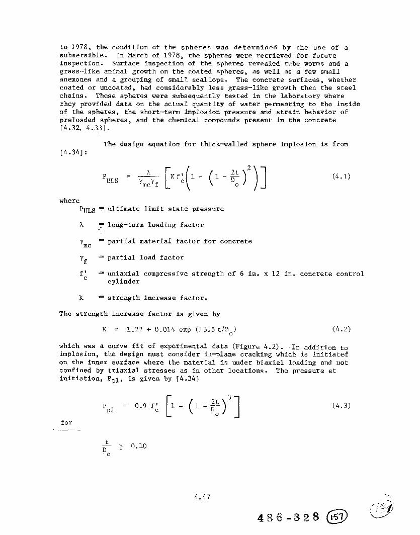
to 1978, the condition of the spheres was determined by the use of asubmersible. In March of 1978, the spheres were retrieved for futureinspection. Surface inspection of the spheres revealed tube worms and agrass-like animal growth on the coated spheres, as well as a few smallanemones and a grouping of small scallops. The concrete surfaces, whethercoated or uncoated, had considerably less grass-like growth than the steelchains. These spheres were subsequently tested in the laboratory wherethey provided data on the actual quantity of water permeating to the insideof the spheres, the short-term implosion pressure and strain behavior ofpreloaded spheres, and the chemical compounds present in the concrete[4.32, 4.33].
The design equation for thick-walled sphere implosion is from[4.34] :
PuL~ = & [f:(’ - (’-%)2)](4.1)
wherepULS =
1’=
mc
‘f =
f; =
K=
ultimate limit state pressure
long-term loading factor
partial material factor for concrete
partial load factor
uniaxial compressive strength of 6 in. x 12 in. concrete controlcylinder
strength increase factor.
The strength increase factor is given by
K = 1.22 + 0.014 exp (13.5t/Do) (4.2)
which was a curve fit of experimental data (Figure 4.2). In addiCion to
implosion, the design must consider in-plane cracking which is initiatedon the inner surface where the material is under biaxial loading and notconfined by triaxial stresses as in other locations. The pressure atinitiation, Ppl, is given by [4.34]
P +-(+’]= 0.9 f’pl
(4.3)
for
4.47

I I.
1 I 1 I I I
11
2.!
u-lw.o
25mu
u-lod
q ‘Jope j as~anu I q@agS
—, -. —-. --- -,------------ . . “. ., , “: . . ..——
4.48
486-328@

Experimental results .(Figure 4.3):seem to verify the formulation.
The results of the test program on spherical shells at theCivil Engineering Laboratory are summarized from feference A.33.
1.
2.
3.
4.
5.
6.
Concrete that was placed in the ocean decreased in compressivestrength by at least 10 percent due to saturation. A time
period of from 1 to 2 years in the ocean was required to regaina strength equal to that of the 28-day fog-cured strength (Figure4.4).
After 5.3 years in the ocean, concrete showed a compressivestrength that was 15 percent greater than its 28-day fog-curedstrength. However, this strength was still 15 percent lessthan companion concrete continuously fog-cured (Figure 4.4).
Three spheres were retrieved from the ocean where they hadbeen exposed to a preload of 50 percent of their ultimatestrength for 5.3 years. These preloaded spheres were testedin the laboratory under short-term loading and, in general,behaved similarly to that of non-preloacled spheres. Whetherpreloaded or non-preloaded, the saturated (uncoated) concretespheres had a tendency to fail at lower pressures than thoseof dry (coated) concrete spheres.
Three of the original 18 spheres have imploded in the oceanunder long-term loading. The remaining spheres have withstoodload levels of 0.3 to 0.8 of their predicted short-term strength.
The permeability of concrete in uncoated spheres has shown adecrease in rate with time and, in several cases, the permeationof sea water through the concrete wall has stopped. Coated(waterproofed) spheres remained dry on the interior (Figure4.5).
X-ray diffraction analysis of the fog-cured and ocean-curedconcrete has shown the”5.3-year ocean-cured concrete, whethercoated or uncoated, to be essentially unchanged from the fog-cured concrete.
The results from this study show undersea concrete structuresto behave exceptionally well at deep ocean depths. The strength,permeability, and durability of the spheres are within or exceed engineeringacceptability limits. Confidence in using concrete for undersea structuresis substantiated and enhanced by the results of this ocean test [4.33].
4.7.3 cyli~drlcal struetur~s
Failure of concrete cylindrical structures under hydrostaticloading can be described by one of three equations: (1) an average wall
4..49

1 cnndkian of &ncrcce m 5.6 YGUS
I I I
f; at 28&y fognominal sc-cngrh. 8,000 pi.
0.8 Io
I2 A
FIGURE 4.4 COMPRESSIVE STRENGTH GAININ DIFFERENT ENVIRONMENTS
(FROM [4.341)
-.*
2J
(
OF CONCRETE
I I I I I
Spheresof 66+.+D by 4.12-in.W*1I
~ Coarcdexrmicmmph (fz
~ Uncos~tdcxccr,Or
/“’”
A 4,185
hCCUmCy Oj e,ch damm pgtit
i. AO.24 ft (7 litcm).
. > 6Time inOc_ (~)
FTGWE 4.5 TOTAL WATER INTAKE FOR SPHERES IN THE OCEANFoR LONG TIME PERIODS (FROM [4.34])
4.50
.-.

stress equation applies to thick-walled cylinders; (2) Donnellrs equation[4.35] to moderately long, thin-walled cylinders; and (3) Bressets equation
[4.36] to long thin-walled cylinders. A series of tests was performed
at the Civil Engineering Laboratory to determine the empirical parametersused in each equation to obtain agreement between the experimental resultsand theoretical expression. This section discusses the analytical and
experimental work which led to a design guide for predicting the implosionof concrete cylinders with a wide range of geometries .(Figure 4.6).
The design approach for unreinforced, thick-walled cylindersis based on an average stress distribution across the wall of the cylinderat implosion. The expression used to predict implosion pressure, pim}for thick-walled cylinders is from [4.37]:
P()
= 2 kcf: ;im
“o
(4.4)
where
kc = 1.25 - 0.12(L/DO) forL/Do < 2
kc = 1.0 for L/D. ~ 2 (L = cylinder length)
was determined empirically. Results for thick-walled cylinders areincorporated into the design guide (Figure.4.6)..,
Thin–walled cylinders are divided into two categories: (1)
moderately long cylinders which are influenced by end-closures whichrestrain the cylinder from instability failure, and (2) long cylinderswhich are not influenced by end closures and behave as infinitely longcylinders. Donnell’s equation is the basis of the determination of theimplosion pressure, Pim, for moderately long cylinders, and Bresse’s~quation is used for long cylinders. Under the assumption that Poisson’sratio (v) equals 0.2 and that the mean radius is approximately equal tothe outside radius of the cylinder, the equations become
Moderately Long Cylinders_—---.,——
1.5
I ()1.25 EirI +-
00 =
L~Do(Donnell)
im
Long Cylinders
2
0.()
= 1.04 Ei~ ; (Bresse)lm
o
“(4..5)
(4:6)
..— —.-. —. ...... .. ,—.
4.51
c)
(
_.&” &“,w ~,,$,,$...,,,!‘! ‘“;’-:.”........

.
—
-i—
+-
. . .
.,,,..——------- . .. . ..————
---
‘\\
\
1’I . . . . .$ . . 0
.—
4.52‘--%
(/+.2

where
Ei = initial elastic modulus
m = plasticity reduction factor.
The initial elastic modulus, Ei, was not measured for each specimen so
an empirical relationship was developed to calculate its value. Figure
4.7 shows the experimental initial elastic moduli data as a function ofcompressive strength. The American Concrete Institute (ACI) expression
for elastic modulus is shown for comparison, along with the followingempirical expression developed in.reference 4.37.
Ei = 530 f’c
(4.7)
A plasticity reduction factor, il,is used in both equations to accountfor inelastic behavior of concrete and specimen out-of-roundness. Valuesof q were determined by calculating the elastic stress at buckling anddividing this stress into the experimental stress at implosion. Fromrepresentative data, a design v curve was selected, which is applicable,—...—.-to both moderately long and long cylinders. The q“expression is, from
[4.37],
()0: (J.
n = 1.65 - 1.25 +# 0.52 < ==<1f’
c c
(4.8)
By substituting expressions (4.7) and (4.8) into .@Wations (4.5)and (4.6), the following results are obtained:
Ifoderately Long Cylinders
1.5
()1090 t
0. ~
<= 1.5
()++830 t
~o
Long Cvlinders
(4.9)
2
0. ()910 t
~Lm—=
If;
()
2
1+690 ;
o
(4.10)
The stress level at implosion, ~im/~~, is calculated by knowing the geometry
of the cylinder structure. The following conditions determine the next step:
(a) If ~im/f~ > 1.0, thick-wall analysis, equation (4.4), is usedto predict implosion,
.—m. —. ...-“.-—— —....—,..—.
4..53.,-=”-.

(b) If 0.52 < ~im/f~ < 1.0, then q is calculated by:~uat:ion {4.8),
(c) If ~im/f~ < 0.52, then T = 1.0.
If conditions (b) or (c) control, the implosion pressure can be computedby substituting equations (4.9) or (4.1O) into the @xpression
g; = ~-; ‘o,— (4.11)Lm im t
where
0.lm = wall stress at implosion
P.lm = implosion pressure
R. = outside radfus
t = average wall thickness.
Equation (4.11) assumes that, near implosion, the stressdistribution across the wall is nearly uniform. The final results for
conditions (b) and (c) are
2.5
()1320 rlf’ t
c ~P =im L/l)
o(4.12)
()3
1? = lloollf’ ;im c
o
(4.13)
All analytical results for the three cylinder types are presentedin Figure 4.6. To determine the Pim/f~ ratio, enter the chart with thestructure’s L/D. and t/D. ratio. Reference “4.37 indicates that themoderately long cylinders are assumed to have simple-support end conditions.If fixed-support end conditions are present, an increase of about 6 percentin implosion strength can be expected.
The reader should refer to &eferences 4.33, 4.34, and 4.37for a complete description of the analytical work and test program conductedat the Cfvfl Engineering Laboratory on subsea spherical and cylindricalstructures.
4.5”4

4.8.1 Introduction
Research in the area of fatigue of concrete structures In themarine environment has been conducted by a large number of organizations.A typical concrete sea structure or ship may be subjected to about 1 x10⁸ waves in its lifetime (20 years), of which about 1 x 10⁷ may createsignificant changes in stress [4.38]. The fatigue characteristics ofthe reinforcements and concrete in air are well known, but the influenceof the marine environment is not accurately defined. The major factors
that influence concrete fatigue strength are [4.39]
o Stress range, history, gradient, and rateo Environmental conditionso Material properties
Evaluating the fatigue capacity of prestressed concrete members in marinefloating structures is complex because the random wave load does notcorrespond to the uniform load cycling of experimental tests. To performan adequate evaluation requires the integration of at least three steps[4.39] :
0 Selection of locations where fatigue stresses may be critical.
o Projection of a load histogram for the structural member.
o Determination of critical fatigue stresses and comparison ofthese to allowable stresses.
The majority of fatigue research in the U.S. has been associatedwith reinforced concrete in an air environment. The ACI Abeles Symposium
[4.401~~~+3,ns;a la~gg..~.gb~r”gf papers @.@h@g ~Es.ga~ih o~..thsfatigue ____strength of reinforcements. The Portland Cement Association (I?CA)haspublished a design bulletin concerning the design of reinforced concrete
.__j~_@~_.f.ar.~gue._(Teference4.41), The major findings of thiS repor_t..wS.YE<..... ,_.——_ “.. . .__r .,r.-_._,,.,=,.J.__,”-, ..,:.—
(1) Presently the effects of cyclic stressing on reinforcing barsare sufficiently well known that safe limits may be placed ontheir usage in ordinary structures and under ordinarycircumstances.
(2) Little or no information is yet available to guide the designerin the use of products such as galvanized reinforcing ‘bars..— ____ _and in applications where environmental extremes or time-dependent effects prevail. Additionally, the effects of barcutoffs and bent-up bars on fatigue strength have not beenfully clarified.
4.,55-1,,
(
o&,,;
486-328 b%

(3) The recent change to the Load Factor method in bridge designspecifications has brought forth a fresh awareness ofserviceability criteria as major design factors. Most design
procedures are sufficiently developed that serviceabilitycriteria are adequate. The influence of serviceabilityrequirements on the final design in some cases has pointedout the need for an improved definition of what service loadingsactually consist of and how they should be applied, for instance,in fatigue design. Service load magnitudes and conditionsare often based on those previously used in Working StressDesign and do not always reflect the reality of extreme serviceconditions. There is, therefore, a need for code writing bodiesto address themselves to such problems.
The Prestressed Concrete Institute (PCI) and Society of NavalArchitects and Marine Engineers (SNAME) both have documents on prestressedconcrete for ocean structures [4.38] and [4.39]. Both reports give generaldiscussion and references for fatigue considerations. SNAME has alsopublished a bulletin specifically on the fatigue of concrete ship structures[4.42]. General conclusions of this report are:
(1) Prestressed concrete subjected to axial loadings with stresseswithin current design limitations will not suffer failure fromhigh-cycle fatigue under a normal service life. The probablelife history of a typical vessel generates stress ranges wellbelow the endurance limits of prestressed concrete and itscomponents (Figures 4.8 and 4.9). Concern should therefore bedirected to low-cycle, high-intensity fatigue, with crackingoccurring at any time in the life history of the vessel. Thislow-cycle fatigue can either be the design storm or a nominal15-day storm history, with the stress range varying from themaximum at one cycle to zero at 2 x 10⁵ cycles.
(2) Any fatigue investigation needs to consider shear (direct shearplus torsional shear) under cyclic loadings. For criticalsections, all shear should be carried either by the concretein permanent compression under prestress or by stirrups. Forthe typical concrete vessel, the provision of substantialvertical prestress in the sides and longitudinal bulkheadswill usually be found to be the optimum solution.
(3) Bond failure under cyclic loading is a primary concern. Itcan be prevented by doubling the code bond length in all criticalareas and by confinement of splices.
(4) Submergence can adversely affect the fatigue life for memberswhich have reopening cracks under cyclic loads. This can and
“>,

//
//
//
\
0
I I I1 I 0 0mk
o u-l oIn N
‘dJO/.29NVH SS3kllS—.
.
P.
o0 0m o 0w w)
~$O/’oZ9NVH SS3M1S
4.57

(5)
(6)
(7)
test and
should be prevented by providing crossing or confining steel,prestressed or passive. For a typical vessel’s hull, thetransverse prestress in the deck and bottom will effectivelyprevent the splittfng along the longitudinal tendons. Thereshould be sufficient steel area in all critical areas to ensurethat if the concrete does crack for any reason, the force canbe transferred to the steel without exceeding the yield strengthof the tendons. This generally requires a total steel percentageof at least 0.8 percent. These provisions for minimum steelarea and confinement will effectively prevent low-cycle high-intensity fatigue.
Structural lightweight aggregate concrete performs similarly,but slightly less effectively than normal concrete in resistingfatigue. In particular, cracking may start at lower tensilestresses; hence, excursions into the tensile range should belimited by reducing maximum tensile stresses. Diagonal tensioncracking should be prevented by providing adequate stirrups.
Prestressing steels have satisfactory fatigue properties atcryogenic temperatures. Conventional steel in the form ofstirrups, etc., may have sharply reduced fatigue strength atvery low temperatures; hence, the use of cold-drawn wire andunstressed prestressing steel should be considered.
With proper design and construction practice, prestressedconcrete vessels can be built which have an acceptably lowprobability of fatigue damage to any component and an extremelylow probability of significant global fatigue failure
a wide range of environmental and service conditions.
Reference ”.4.2indicates that, based on a survey of existingfield data, fatigue for a prestressed concrete vessel is only a
critical criterion at the low-cycle, high-intensity end of the spectrum.
Because of the lack of data on the effects of submergence,frequency, and cracking, referenc~-4.42 recommended that a research. .. ...—-.test program should be conducted on concrete both in air and submergedin salt water to a head of 10 to 20 m (32 to 64 ft.). Such a programwould consider prestressed concrete slabs, posttentioned longitudinallyand transversely to about 8 and 5.5 MPa (1,200 and 800 psi), respectively.Mild steel reinforcement would be installed on both faces in bothdirections. Testing would be at a frequency of about 0.1 Hertz,representative of storm waves. The concrete would be axially stressedto cracking in the tensile range (so as to produce cracks of width 0.1to 0.5 mm (0.004 to 0.02 in.) and to 40 percent to 60 percent f: in thecompressive range.
“--%
4..58 ,/./;? ;F
,/5’-/4$&3,2g (@ ““-”’

Reference 4.42 also recommends that similar tests be conductedin cyclic shear (so as to simulate the action on the side of the vessel).The loading would produce cracking in diagonal tension, thus simulatingthe extreme loads anticipated during a vesselfs lifetime.
Various European codes and recommended design procedures haveincorporated fatigue considerations. For example, the Det norske Veritas
rules [2.1] introduc~its section...og._.fatig.ue_wiCh.zb~_.f~l_lowlng.._._._.._..__paragraph.
“The fatigue strength of reinforced and prestressed offshoreconcrete structures is presently not well documented. Earlier
experience on structures cannot easily be extrapolated sincestructural parts of offshore structures are exposed to moredynamic and complex loading than other structures, includingthe effect of hydrostatic pressure.”
These rules cover the areas of (1) cumulative fatigue damage, (2) concretecompressive, flexural and shear strengths, (3) bond between reinforcementand concrete, and. (4) reinforcement and tendon strength. Waagaard [4.43]at DnV, project leader for the COSMAR program on fatigue, published anarticle on the fatigue strength of offshore concrete structures, in whichthe following rules and guidelines were reviewed:
o Det Norske Veritas “Rules for the Design, Construction andInspection of Offshore Structures,” Appendix D - ConcreteStructures” [2.1]
o FIP “Recommendations for the Design and Construction of OffshoreSea Structures” [4.13]
o ACI “Guide for the Design and Construction of Fixed OffshoreConcrete Structures’m [2.8]
o Norwegian Petroleum Directorate “Regulation for the Structural
Design of Fixed Structures on the Norwegian Continental Shelf”[4.44].
The above were reviewed with respect to the following parameters:
o S-N curves for concrete in compression
o Cracking limitations
o S-N curves for reinforcement
o Transverse shear capacity
o Cumulative fatigue life
4..59
( , & ,,,
c),j’ -J , ;
4&fj.328 Jb’? ‘<c.---’’”

Major conclusions from [4.43] were:
(1) The random nature of environmental loading on an offshoreinstallation has made it necessary for the designer to go intogreater detail in fatigue strength evaluations. Cumulativeanalyses with the help of Minerrs hypothesis has shown thatthe variation in the Miner sum is both a variable of concretestrength variation and of loading sequence. The Miner sumshould, for random loading when applied to concrete structures,be less than one.
(2) h converting experimental data into design, one should ensurethat the same method is used in evaluating the test data asis used in design. Fatigue curves will, for example, be methoddependent, and direct comparisons of levels of fatigue curvesmay not adequately represent an evaluation of the safety fordifferent requirements.
(3) It is important to note that the marine environment has adeteriorating influence on the fatigue properties of bothconcrete and reinforcements. From an evaluation of actualstress and cracking conditions, the behavior of concrete andtendons in fatigue will need the most careful consideration.In concrete, both the effect of pumping water in and out ofcracks and the effect of pore pressure should be included inthe analysis.
A number of experimental efforts on the fatigue behavior ofconcrete are being conducted under the auspices of the European researchprograms described in Sections 4.3 - 4.5. Recent results are reportedin references 4.43 and 4.45 – 4.48. The Europem”.work currentlyin progress does address some of the questions concerning fatigue raisedby Gerwick [4.42] and mentioned in Section 4.8.2; namely,
o the effect of sea water corrosion
o the effect of loading frequency.
The interaction between corrosion and the loading frequencyis a complex phenomenon. For example, it has been well established thatin steels, corrosion fatigue is frequency dependent. Fatigue tests inair are generally frequency independent, but tests conducted in sea waterat about 0.1 to 0.2 Hertz (typical ocean wave frequencies) show a decreasein fatigue llfe by a factor of about of two to five. If the frequencyof the sea water tests is Increased to above about one Hertz, the corrosionfatigue effect on steel essentially disappears, and the fatigue life isrestored to the in-air value. Therefore, it is important to conduct suchtests under the expected loading frequencies. The process is furthercomplicated by the buildup, with time, of deposits in the cracks of the
4.60
04869328 Iq”
-1,

concrete. These deposits consist primarily of calcium carbonate (CaC03)and/or magnesium hydroxide (Mg (oH)2). In fatigue tests on reinforcedconcrete beams, European investigators [4.45, 4.46] have found a markeddecrease in deflections due to blockage of cracks by these deposits.Figures 4.10 and 4.11 show typical reinforced concrete beam specimensand loading arrangement for unidirectional and reverse bending. The centerportion of the concrete beam is immersed in a tank containing the seawater . Controls are generally established on water salinity, temperature,pH level, and flow rate.
The tests generally reveal a deleterious effect of the seawater corrosion on the fatigue life of the reinforced beams. Figure 4.12shows some interesting results from reference 4,45. Underu-bidirectionalbending, the fatigue life (0) in sea water (conducted at 0.17 Hz) appearsto be enhanced, even over the expected life in air (X). The investigatorsattribute this to blockage of the cracks on the tension side, which reducesthe stress range in the reinforcing bars. However, under reverse bending,blocking of the cracks on both sides of the beam occurs with an increasein mean stress but no decrease in stKess.range.. ~e~,c:e-,the fatigue life
is reduced compared with in-air tests. This last observation is confirmedby other investigators [4.47, 4.48]. The increased fatigue life in waterunder unidirectional loading reported in:+e:~e.~-.~nc”e.4;45”h-as“rio:t..b.eenconfirmed, and work is still ongoing to resolve these differences.
Only a limited number of fatigue tests have been conductedunder a simulated water depth. Reference 4“.4-5..iiid~”&atPs”that ti.ttio”tests completed at 30-m depth , at a stress range of 360 MPa and 0.1 Hertz,there was no evidence of any greater spalling of the concrete at cracksthan had occurred in the tests at atmospheric pressure in a sea waterenvironment.
4.9 Strength
4.9.1 Introduction
Reinforced concrete used in floating marine structures willbe subjected to a variety of loading conditions. The primary deflectionand stress response of the entire hull behaving as a beam, the secondaryresponse of a local stiffened panel, and tertiary response of the shellbetween stiffeners, must be analyzed during the design of the structure.A primary consideration in the design is the strength, usually definedas a function of the ultimate compressive strength of the concrete elements.When considering a floating structure, the strength/weight ratio of theconcrete is the controlling factor rather than strength alone.
Concrete for marine applications can be divided into severalmajor categories according to its weight and strength (Table 4’.13):—..
4.61.,,
(:-”’,,
0486-328 171 “-–’”

.s. .—
.
.
C-52
*r
L
-E
“T-
!lamac
--.-,+_—.-...—..—...———-.“.-.
—
—
/-,. . .. ...
E+cc
t--’--i P4c
d
2
—
..——.-..,-. ----- ~- !“-”:““”.
,- JJ,(
---- --

‘z’1 .<..7I
.
.--——.—Zz
au.<l_..-.
+-+
i
. . -
(
LXagf’aa I
o0.0
-t ml (Zd—“—-------
m A
SS3us ._ ,,.+--”””-’--”-”—---
4.63
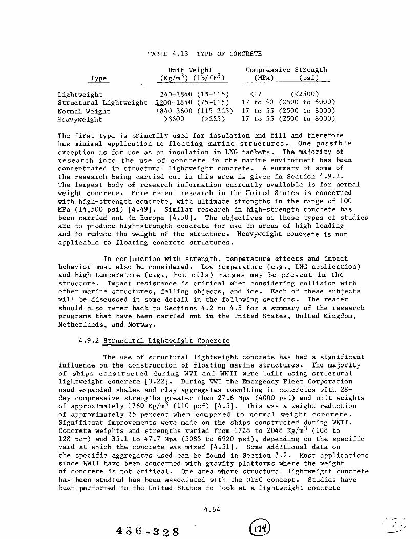
TMLE 4.13 TYPE OF CONCRETE
Unit Weight Compressive StrengthType (Kg/m3) (lb/ft3) (MPa) (psi)
Lightweight 240-1840 (15-115) <17 (<2500)Structural Lightweight 1200-.1840 (75-115) 17 to 40 (2500 to 6000)
Normal Weight 1840-3600 (115-225) 17 to 55 (2500 to 8000)Heavyweight >3600 (>225) 17 tO 55 (2500 tO 8000)
The first type is primarily used for insulation and fill and thereforehas minimal application toexception is for use as anresearch into the use ofconcentrated in structuralthe research being carried
floating marine structures. One possibleinsulation in LNG tankers. The majority of
concrete in the marine environment has beenlightweight concrete. A summary of some ofout in this area is given in Section 4.9.2.
The largestlbody of research information currently available is for normalweight concrete. More recent research in the United States is concernedwith high–strength concrete , with ultimate strengths in the range of 100MPa (14,500 psi) [4.49]. Similar research in high-strength concrete hasbeen carried out in Europe [4.50]. The objectives of these types of studiesare to produce high–strength concrete for use in areas of high loadingand to reduce the weight of the structure. Heav~eight concrete is notapplicable to floating concrete structures.
In conjunction with strength, temperature effects and impactbehavior must also be considered. Low temperature (e.g., LNG application)and high temperature (e.g., hot oils) ranges may be present in thestructure. Impact resistance is critical when considering collision withother marine structures, falling objects, and ice. Each of these subjectswill be discussed in some detail in the following sections. The readershould also refer back to Sections 4.2 to 4.5 for a summary of the researchprograms that have been carried out in the United States, United Kingdom,Netherlands, and Norway.
4.9.2 Structural Lightweight Concrete
The use of structural lightweight concrete has had a significantinfluence on the construction of floating marine structures. The majorityof ships constructed during WWI and wWII were built using structurallightweight concrete [3.22]. During WWI the Emergency Fleet Corporationused expanded shales and clay aggregates resulting in concretes with 28-day compressive strengths
frester than 27.6 Mpa (4000 psi) and unit weights
of approximately 1760 Kg/m (110 pcf) [4.5]. T%is was a weight reductionof approximately 25 percent when compared to normal weight concrete.Significant improvements were made on the ships constructed during WWI1.Concrete weights and strengths varied from 1728 to 2048 Kg/m3 (108 to128 pcf) and 35.1 to 47.7 Mpa (5085 to 6920 psi), depending on the specificyard at which the concrete was mixed [4.51]. Some additional data onthe specific aggregates used can be found in Section 3.2. Most applicationssince WWII have been concerned with gravity platforms where the weightof concrete is not critical. One area where structural lightweight concretehas been studied has been associated with the OTEC concept. Studies havebeen performed in the United States to look at a lightweight concrete
4.64
486-3z8 - 0Wf

using a polymer-filled aggregate (PFA) [4.52]. In addition, several review
studies have appeared in Europe [4.14, 4.16].
T. A. Holmes has compiled a summary of the performance ofstructural lightweight concrete in the marine environment [4.53]. ThisAmerican Concrete Institute publication addresses both the historical
aspects and several areas of research. Work in freeze-thaw testing suchas discussed in Section 4.6 at the Treat Island, Maine, Concrete ExposureStation, is briefly summarized by Holmes:
One interesting characteristic of structural lightweight concrete wasthat the elastic moduli of the mortar,By contrast,
aggregate, and concrete were similarnormal weight concrete has a much larger aggregate modulus,
and the strength is limited by the mortar strength. The resulting overallstrengths of the two types are therefore often similar. Holmes pointsout that the compressive strength of structural lightweight concrete islimited by the “particle strength of the largest piece of lightweightaggregate .*’ In most instances the long-term strength of lightweightconcrete was “equal to or greater than normal weight concretes with equalbinder content.”
One example of a program designed to improve the strength ofthe lightweight aggregate was that performed at the Civil EngineeringLaboratory in connection with the OTEC program [4.52]. In this programthe voids in the aggregate were impregnated with polymeric material witha specific gravity near one. In this way the weight of the polymer-filledaggregate concrete when submersed in water would not be any larger thanthat of normal structural lightweight concrete, but its strength wouldbe improved. The results of this study are summarized in Table 4.14.The compressive strength increased by 26 percent, with failure occurringin the bond between the aggregate and cement matrix. Both the split tensilestrength and elastic modulus of PFA showed only slight increases overnormal structural lightweight concrete. Although the lightweight concretecan offer a savings in the total weight of marine structures when comparedto normal weight concrete, additional costs associated with productionof lightweight aggregate should be considered.
Two summaries of the use of lightweight concrete for marineapplications have been published by the European community [4.14, 4.16].These reviews consider the density, strength under various loads,deformation behavior, creep and shrinkage characteristics, thermalproperties, durability, design, and construction. As noted earlier, thestrengths of structural lightweight concretes are controlled by both thestrengths of the individual aggregate as well as the aggregate to mortarbond . Concretes of strengths greater than 70 MPa (10,000 psi) withdensities less than 2,000 Kg/m3 (125 pcf) are obtainable [4.16]. Severalareas of research recommended include [4.16]:
..,: r’-,,“ !>/,
:.—--.”-
4.65
—

TABLE 4.14. COMPARISON OF LIGHTWEIGHT AND NORMAL WEIGHT CONCRETE
1
&cmm
&J-%3
cm
CompressiveStwngtll”
&Mix
No.Rcgu~m
13,840
4.6“
24,700
5.7
35,180
2.7I
G
(psi)
PFA
4,4503.6
5,9401.3
6,4006.1
6,580
3.8
?/iDifference
+15.8
+26.4
+23.6
+26.5
uAverageofsixspccimms.
bAverageoffive spccimcns.
cAverageofthree spccinlcns.
d1%0diffcrcncc= “F* -l<c~L1l;lr(100)
Rcgukr,,-----
“Coefficientofvariation.
FROM [4.52]
SplitTensileStrcngd]h I ElasticM,ocfulus(psi)
Regular P17A
420 430
5.0 2.6
470 5002.3 3.7
480 500
5.9 5.0
500 52011.2 5.5
I (xIO”psi)[
%ReguIar
Di[fcrti ncc
=7=
-t”4.4
+6.4 1.963.8
+
+4.2 2.080.0
+4.0 2.191.3
PFA
1.782.0
2.03
0.0
2.14
8.3
2.41
1.4
%Difference
o
+3.6
+2.9
+10.0
Poisson’s Ratio
Regular PFAYo
DiffercnrcI I
0.26 0.21 -19.2?6.8 0.0
0.25 0.27 +8.06.o 2.1
0.25 0.28 +12.011.4 12.4
0.24 0.22 –f3.33.6 10.3

(1)
(2)
(3)
(4)
Behavior When subjected to multiaxial loads occurring inmarine structures.
Studies of thick-walled lightweight (<1500 Kg/m3, 95 pcf)concretes when subjected to a low temperature LNGenvironment.
The long–term strength and density of lightweight concretewhen subjected to long–term hydrostatic heads.
Studies of surface impregnation of polymers subjected toincreased corrosion and abrasion.
Reference 4.14 contains the following summary of the advantages .anddisadvantages of structural lightweight concrete.
(1) Additional buoyancy can be achieved by the use of a lighter
concrete in floating structures.
(2) Reinforcement and prestressing steel economy can be madein structures where a lighter concrete is used, particularlywhere the ratio of dead load to superimposed load is high.
(3) Lighter structures afford savings in foundations andpiling work.
(4) Lightweight aggregates are porous and stable. They arebetter than dense aggregates where insulation is required,as in cryogenic design and for fire resistance.
(5) Lightweight concrete exhibits better crack behavior dueto shrinkage, creep, and thermal expansion.
(6) Lightweight concrete has better energy absorptioncharacteristics from impact and cyclic loading.
(7) Lightweight concrete in construction can show considerablesavings on transport, formwork, concrete placement, andplant maintenance.
(8) The ability to cut, drill, and fix attachments to structurallightweight concrete is enhanced.
Disadvantages
(1) Lightweight aggregates are more expensive than naturallyoccurring dense aggregates.
(2) High-strength lightweight concretes may require more cementcontent in the mix, depending upon the aggregate chosen.
4.67

(3) Larger prestressing losses arise from the lower modulusof elasticity and larger shrinkage and creep.
(4) Greater care is required in controlling water content,mixing of lightweight concretes, and supervision to maintainstrength and workability requirements.
(5) Porous aggregates require special measures to pump theconcrete.
4.9.3 Temperature Effects
Concrete used in marine structures will be exposed to a widevariety of temperatures from both cargo and the exterior environment. Alarge number of research programs have been carried out concerning theinfluence of the external environment on concrete structures. These includethe durability studies carried out at Treat Island described in Section4.6. Durability of concrete is influenced by both external environmentalconditions, to be discussed in a later section, and internal conditions,to be discussed here.
A number of studies related to this subject have already beennoted in this report.
(1) Table 4.5 Project NO. 3Experimental Investigation of the Effects of TemperatureGradients on the Walls of Oil Storage Structures
(2) Table 4.6 Project No. 4Temperature Gradients
(3) Table 4.6 Project No. D6.8Temperature Gradients
(4) Table 4.9 Project No. BK-5Influence of Temperature Changes on Concrete
(5) Table 4.11 Project No. 3Development of Concrete Structures for Storage, andTransportation of LNG and Oil Including Thermal Effects
GiiVestigators [4.54] studied :thk use of prestressed concrete
as both primary and secondary barriers for LNG and LPG ships and bargesand reported, “Prestressed concrete is the only material normally usedat ambient temperature conditions that can also be used structurally atcyrogenic temperatures.” Results of this work indicate that concretehas advantages when compared to steel for LNG/LPG application becauseits thermal response is slower, thereby resulting in less thermal shockand local temperature effects. As noted earlier in this report, additionaleffort is required to study the influence of temperature variations onthick shell structures. The European studies should provide some additionalknowledge In this area.
486-%28(34.68

4.9.4 Impact Behavior
An important consideration in the design of any floating marinestructure is its resistance to impact loads. The loads can be the resultof collisions with other vessels, stationary structures, icebergs oraccidental loads such as fallen drilling pipe. As has been noted inSections 3.2, 3.3 and 3.4, concrete structures have been found to beresistant to impact. A number of studies concerned with the impactresistance of concrete in conventional nuclear power plant design areavailable. These studies explore the impact resistance of concrete when
struck by missiles such as hurricane-thrown telephone poles. In most
cases analytical analysis of the problem is performed using either finiteelement or finite difference methods [4.55]. Additional studies on oceanstructures are being carried out in conjunction with the Concrete in theOcean Program (Tib.E&:4”,~-~fid”4.6).
4.10 Durability of Reinforced Concrete
4.10.1 Introduction
A practical consideration in the use of reinforced concretefor floating marine structures is its durability. In fact one of themain advantages of concrete over steel is the minimum maintenance requiredfor a well-designed concrete structure. This section will look at someof the recent research programs examining the long-term durability ofconcrete and related subjects such as permeability, corrosion, abrasion,and resistance to chemical attack and marine organisms. The durability
of concrete is a function of both the external conditions and the materialcharacteristics of the hardened concrete and reinforcing steel.
Environmental exposure of a marine structure can be classifiedas occurring in three zones: (1) Atmospheric, (2) Tidal, and (3) Submerged[4.56]. Each of these zones has specific processes of deteriorationassociated with them, Figure 4.13. They include cracking due to corrosionof steel reinforcements, cracking due to freeze/thaw cycles, physicalabrasion, and chemical decomposition. The material characteristics ofthe concrete plays an important role in its durability. The most importantaspect is the permeability of the concrete which can be controlled bythe permeability of the cement paste and the choice of aggregate. Themix must be designed for a high cement content and low water/cement ratiowith additives to increase workability. In addition to a good mix, itis necessary to ensure that good construction practices are followed sothat the concrete is compact, homogeneous, and has a smooth surface. Ifthe proper mix is used, good construction practice followed, and a designto prevent local cracking generated, reinforced concrete will produce adurable floating marine structure.
4.69

‘NCRETE=REINFORCING STEEL
CRACKINGDUE TO
+4
CORROSIONOF STEEL—
CRACKINGDUE TOFREEZING AND THAWING
---i!PHYSICAL ABRASION DUE TOWAVE ACTION, SAND ANDGRAVEL AND FLOATING ICE
........ .,.. ,. ,, ,, ,
..’, ,~, ,,’, L-!. ,, l’,, ,,, ,,
WEMICAL 0f+0MP051TIoN PAT&1,CO*”,ATT.ACK :‘
,’2Mu ION Al_FACK, “. .’,,,3.SULFATE#?T@K-
,, —
IATMOSPHERIC ZONE
‘f’ F’.-+” TIDAL”ZONE
I
Fs“-~~ --— —“.,— ,!
1 ‘ ~~,,-,-, l-’
“. ‘1,,. ,, .,~,, ->,., .. ,,,.- .:
SUBMERGED ZONE ;
.,. ,.:, !,:., d
-—..
FIGURE 4.13. DETERIORATION OF A CONCRETE STRUCTUREIN SEA WATER (FROM [4.56])
The American Concrete Institute has published two booksconcerned with the durability of concrete [4.57, 4.58], which describein detail a number of research programs on the subject. In the introductorypaper in the second book, Mehta presents a review of the durability ofconcrete in sea water [4.56]. The following excerpt from this papersummarizes the results of case histories of concrete exposed to the marineenvironment .
Whether thes~ zeed~ tuvn into deleterious produete dependsmainly on the ability of a concrete to keep mtw from penetratinginto the intevio~. Thus, the second lezson from the above ea~ehistories of concrete failures iz that permeability of concreteis the mo~t important propwty o%wmining long-te~m durability.Again, from the ease lrbtor<ez of deteriorated concretes, -thefollouing eauze~ fop lack of ude~-tightness can be -identified:
4.70
,-
.>, ... ,.,’ )’”.,.,”../-”

(i) Imp?opw mix d~sign: Permeability of eoner~te i~dwived mainly from the pe~meability of e~ment ~st~. Low cementcontent and high-ii)atareemazt mtio produce a readily permeableproduct on hydration. PooFly graded aggwgate can al~o be aEOUFCQ of lack of ua-ter-tigktnes.~.
(~~) Poor Concmt~ng Practice: EvE?n a high quality cone?%kem~xturw can yield a permeable concrete ~~ the concwte is notp~operly compacted. Poorly condrwcted jo-intz can al~o pwm~tpereolat~on of Mater. CavelQs8ness in placement, sue% asgeg~egation of concwte mixture and formation of thick layer~of Zaitanee at ~oints, or dilution of concrete mixture withadditional um%~, has frequently been identified az a zoureeof cone~ete permeability.
(iii) C?ackg in Concrete: Despite good quality of eonevetaand p~opar oo~kman+ip, concrete ztructurez may yet be permeableto sea wte~ if tlzaydevelop cracks du~ing the COUPEQ of theirEewice life. Among the common 80UPCG8 of cracking a?e excezsivedeflection due to load, carele~zne~~ in tran~po~ting precastmember~ and driving preca~t p-ile~, the~mal stres~es due -totemperatuw gmzdient in th.iek cone~ete stww.tures, free,ze-thawcycles on non-ai~-entrained concrete, co~ro~ion of winfo~cingstee~ and expan~ive chemical watt-ion~ such a~ these involvingformation of ettringite and alkali-~iliea gel.
Anothev lez~on from the ease higtories of eoneretadeterio~ation in sea uwte~ is that, depending on the tidal line~,the individwl proee~ses of detmioration tend to limit themselve~to different prt~ of a st~ucture. From this standpoint astructure can be divided into tlmwe zones (illustratedby Figure4.13). The upp~most ~rt , dzich is above the high-tide line,is not d-irectlyexposed to s~a uat~r. Houever, it i% aposedto atmosphepie ai?, tinds camying sea Gaits, and frostiaction.Consequently, eraek-ingdue to cor~osion of winforcement inconcrete and/or f~eezing and thauing of concrete are thepredominant deleterious phenomena in thiz zone. l!k.estwatu~ein the tidal zone, uhieh iz betueen high–tide and lowtide mark,is not only vulne~able to cracking and spalling of eone~etedue to uetting and d~ying, f~ost action, and co~~ozion of~einfo?cament, but also to ZOS6 of mata+al due to ehemiealdecompo&tion of hyd~ation p~oductz of cement, and im~et ofL.W.WS containing floating ice, zand, and gravel. The loue~part of the ~t~uctu~e, which is alwys subme~ged in .wa wter,is vulnerable to ~t~ength FetPogresGion and Lozs of matw+alas a Wzult of the chemical reactions betueen zea inter andhydration ~oducts of cement. Due to the ab~ence of frost actionand due to lack of oxygen, cracking of conc~ete due to f~eeze-thaw cycles and eomosion of the r&nforeing zteel is seldom apoblem here.
4.71
.r-‘.,., 486-3@j
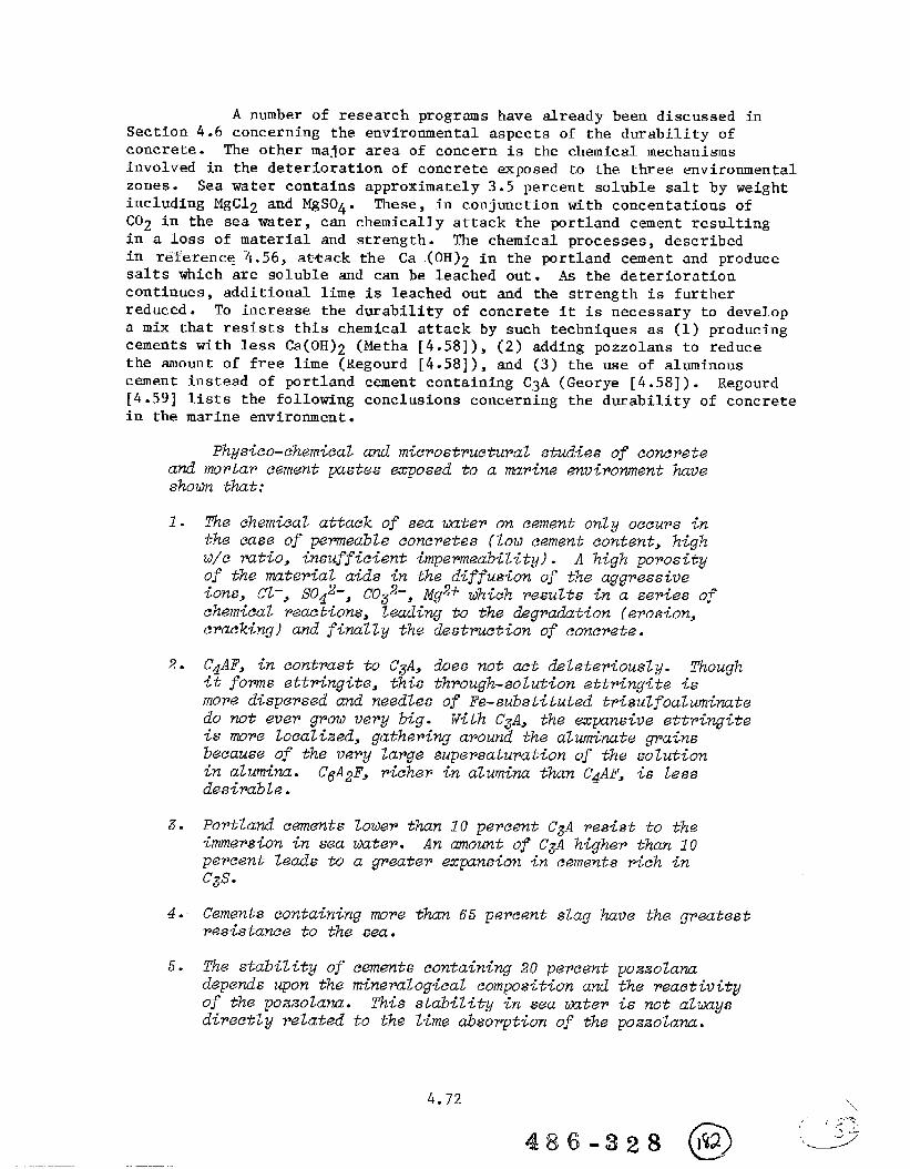
A number of research programs have already been discussed inSection 4.6 concerning the environmental aspects of the durability ofconcrete. The other major area of concern is the chemical mechanismsinvolved in the deterioration of concrete exposed to the three environmentalzones. Sea water contains approximately 3.5 percent soluble salt by weightincluding MgC12 and MgS04. These, in conjunction with concentrations ofC02 in the sea water , can chemically attack the portland cement resultingin a loss of material and strength. The chemical processes, describedin reference “4.56, at-fiackthe Ca ,(OH)2 in the portland cement and producesalts which are soluble and can be leached out. As the deteriorationcontinues , additional lime is leached out and the strength is furtherreduced. To increase the durability of concrete it is necessary to developa mix that resists this chemical attack by such techniques as (1) producingcements with less Ca(OH)2 (Metha [4.58]), (2) adding pozzolans to reducethe amount of free lime (Regourd [4.58]), and (3) the use of alumlnouscement instead of portland cement containing C3A (Georye [4.58]). Regourd[4.59] lists the following conclusions concerning the durability of concretein the marine environment.
1. The ehem~eal attack of zea um%r on cement only oecupg inthe ease of permeable eoncpete~ (1OM cemmt content, h.@hM/e vat~o, ~nsuff~e<ent ~mpermeab<l~ty). A Wgh. po~osityof the mater~al a~dz in the diffug{on of the agg~a~~-iveions, CL-, S042-, C032-, Mg2+ tilriehwzult~ in a se~-iesofchemical reactions, leading to -W &graakt~on (ero~ion,e~aeking) and finally the destruction of concwte,
486-328 (@ ‘~,..,.-7,.
“-.“.’s“
2
4.72
Abrasion and marine organism attacks can also affect thedurability of concrete. The abrasion resistance of concrete is a functionof the compressive strength , aggregate properties, and finishing and curingmethods [4.5, 4.60]. For most marine concrete structures, the compressivestrength is adequate to prevent abrasion. Finishing should be such thatthe surface concrete is smooth, compact, and strong. The main problemwith marine organisms is due to fouling , which increases hull weight andfrictional resistance. There is little chance of damage due to attackof organisms. Reference ~4.60 is a good-general reference on thedurability of concrete.
4.10.2 Permeability
Permeability is the most important characteristic determining
the long-term durability of concrete exposed to sea water [4.56].Permeability, defined as the rate at which a liquid will penetrate theconcrete, controls the rate of chemical attack, the amount of freeze-thaw damage and the rate of reinforcement corrosion [4.5]. The permeabilityof concrete is a function of the size, distribution, and continuity ofvoids in the hardened material. Voids In concrete can be divided intoseveral groups [4.61].
(1) Air voids due to mix and placing or the addition of airentrainers to reduce susceptibility to freeze–thaw cycles.
(2) Submicroscopic capillary voids that are created by spaceoriginally occupied by the mix water.
(3) Submicroscopic gel voids that are created as cementhydrates.
(4) Voids found in normal and lightweight aggregate particles.
(5) Internal cracks due to loading.
(6) Voids around aggregate due to bleed water in high water-to-cement ratio mixes.
(7) Honeycomb voids due to dry mixes and poorly compactedconcrete.
lh most cases , air voids are discrete and therefore have littleinfluence on the permeability. During the process of hydration thecapillary void volume due to the water decreases as the result of theformation of calcium-silicate–hydrate gel, whose volume is 60 percentgreater than the original size of the cement grain. The net result is areplacement of capillary voids by gel voids which are smaller in size.The largest voids in hardened concrete are those that occur in the
o486-328 )%3
4.73 ‘“““Y,

aggregate. The last three types of voids listed above can be eliminated,to a great extent, by proper design, mixing, and placing [4.61].
The important aspects in limiting the permeability of concreteare mixes that have water–cement ratios near 0.4 and have sufficient amountsof cements. These will limit the amount of capillary and gel voids, therebyreducing the permeability of concrete. The effect of the water-cementratio can be easily seen from Figure 4.14. Another interesting fact isthat the permeability of concrete immersed in sea water tends to decreasewith time, adding to its durability.
4.10.3 Corrosion
Another factor that must be considered is the corrosion ofthe steel reinforcing in the concrete. Corrosion of steel in concreteis an electrochemical process which depends on electrical resistivity ofthe material, pliof the cement paste in contact with steel, and diffusionof chlorides and oxygen into the concrete [4.56]. For structures exposedto a humid environment, the electrical resistivity has only minor influenceand RH and chloride diffusion tend to control the rate of corrosion. Thecorrosion process can be divided into initiation, propagation, and finalphases. The process of hydration of the cement results in the formationof a passive iron oxide film on the surface of most of the steel. Thisfilm and the free lime (pH x 12.5) protects the steel from further corrosionuntil the permeability allows chloride and oxygen to infiltrate the concreteto the steel and propagation begins. During the initiation phase theanodic reaction
Fe -1-3(OH)– + 1/2 Fe@3 - 3H20 i-3e–
produces the protective film [4.56], As the concentration of chloridesincreases relative to the (OH)– concentration, the anodic reaction becomes[4.56]:
Fe + 2C1- + FeC12 +’Fe+ + 2C1- + 2e-
with a corresponding cathodfc reaction if oxygen is present
1/2 02 +H20+ 2e-~2 (OH)-
As this process continues, the area of the steel is slowly reduced. Thefinal phase occurs when the formation of rust , which has a larger volumethan the iron, causes the concrete to crack and span, further increasingthe corrosion rate.
Tuutti [4.63] has done extensive research into proceduresdesigned to indicate the service lifetime of a reinforced concrete structureincluding the initiation and propagation phases. The four steps in thisprocedure are:
(1) Compile the relevant materials, structural, andenvironmental data.
w5-328@
4.74

140
120
100
80
60
40
20
0
/
0.2 0.3 ().4 0.5 0,6 0.7 0.8
Water-Cement Ratio. .—
FIGURE 4.14. EFFECT OF WATER-CEMENT RATIOON PERMEABILITY (FROM [4.62])
,.
4.75
486.328@
(2) Calculate initiation time including carbonation andchloride initiation.
(3) Calculate the relevant corrosion rate in the propagation
stage.
(4) Calculate the maximum corrosion depth.
These procedures, described in Ceference 4.63, are based on analysis,testing, and observation of structures.
Browne [4.64] describes the mechanisms involved and measurementsmade in looking at the corrosion of steel in concrete. The procedures
he describes to predict the initiation and propagation times are similarto those described by Tuutti. Some of the conclusions of this paper are:
1% upp~oaeh deze~ibed in the pper mzublec the tine (to)to ae.t+vate tk ztieel to be estimated, of value to the designfor life zpecifieation, a~ uell as, the t~me to zpall (tl).Further colleet~on of data on actual ~trueturez till odd tothe eonftienee in u~ing thb approach.
From this approach it iG hoped tihatin the near j%tur~, aztronger tiziz can be formulated -innational eodez fop the designfop dupability related to:
(a) the thickness of cover(b) the quality and type of eonc~ete requ<red % the cover
zone(cl the curing of the concrete surface layws(d) the coating of potentially vulnerable awas
The abotieitems aw interrelated. I%UG for a zpeeifieddesign life in the agg~essive atmo~phep~e zone, -in the futurea lo~ diffu~ion concrete, ~all cured, might be speeifiad tuenable the eovm to be reduced. Thareby, the size of struetu~alerack~ may be wduced and obtain a zaving <n ue<ght--provided,of COUPSQ, it is not fu~ther wdue.ed -inthe actual structureby pooP vorkmanzh~p. Further a ~urface eoat~ng to {nh<bitchloride ing~ess could be applied to provide an additional ~afe-tyf~tor and substantially enhance the life, o? alternatively,allov ~eduetions in eone~ete quality OF cover thickness forthe same design life.
UndewJater, conventional concrete struetu~as in saazaatapare less mibwrable due to lack of oxygen. Offzhore stmmtureshava to be considered mope carefully as unique situations ew%tdue, for example, to availability of oxygen from intierwallydry shafts, to wre onerous dynamic moe Zoading condition~,to applied la~ge ~cale ea-thodicprotection systems and to -themacro-scale of these struetuws.
.,,,/
,.-!, .- .
“?-=,,&.
“~—”
4.76

4.11 Inspection and Repair
4.11.1 Introduction
As more and more concrete structures are built for use inthe marine environment, the subject of inspection and repair becomesimportant. To ensure the continued safe operation of floating concretestructures, periodic inspection should be made. If signs of concretecracking or spalling and reinforcement corrosion are observed, the extentof damage must be determined and its effect on the structural performanceanalyzed. Prior to repair of the structure, the cause of the damage mustbe determined and resolved, if possible, so that future problems can beeliminated. The materials and practices used to repair the structuremust be of a sufficient quality to ensure that the structure will continueto satisfy its design requirements.
Inspection of concrete structures has been performed in allphases of the concrete construction industry. A recent review[4.5] looks at the specific requirements of reinforced concrete vessels.Two areas where the repair of damaged structures has been studied havebeen those exposed to abrasion as the result of moving fluids and earthquakedamaged structures. The unique aspect of marine structures is that threezones of environmental conditions must be considered for inspection andrepair: atmospheric, splash, and submerged. Each of these regions offersslightly different problems.
4.11.2 Inspection
Periodic inspection of marine structures is required byclassification societies, and these inspections are designed to ensurethe continued safe operation of the structures. Inspections are performedduring construction as well as periodically during the service life.
(1) Inspection Before Concreting [4.5]
Prior to placement of concrete it is essential thatreinforcement, prestressing tendons, formwork and embedments,and construction joints be inspected. This inspection is intendedto ensure that all reinforcement and embedded items are properlyplaced and secured in position, and that formwork is correctlypositioned to obtain final dimensions within tolerance limitationsof the construction specifications. Once concrete is cast itis extremely difficult to correct deficiencies that may haveoccurred during fabrication and placing of reinforcement,embedments, and formwork.
4.77
...,-
,,.,-;“J”:’/ -’
-— /“

(2) Inspection During Concreting [4.5]
General recommendations for measuring, mixing,transporting, and placing concrete are given by ACI Committee304 [4.65]. These recommendations are applicable to use ofconcrete in marine structures. Checks of the batching, mixingand transportation procedures must be made to ensure that concreteof uniform quality and meeting construction specification isproduced. Placing practices should be controlled to ensurethe development of a uniform mix. In addition, control tests,including slump, unit weight, air content, temperature, andstrength should be conducted as required.
(3) Inspection After Concreting [4.5]
After concreting is coinpleted it is necessary to ensurethat concrete is properly finished and cured and that formworkremoval does not damage the young concrete or threaten safetyof construction workers. Additional operations after concretinginclude evaluation of strength of hardened concrete, post-tensioning, and grouting.
(4) In-Service Inspection [4.5]
After a vessel has been constructed and put intoservice, it should be surveyed on a periodic basis for signsof deterioration of concrete, corrosion of reinforcement, and
damage from overload, impact, abrasion, or fire. A well-designed
and properly constructed concrete vessel should have a longservice life.
It is this last phase that is unique to the marine concretestructure. There are three zones that will require inspection. Conditionsin the atmospheric zone are similar to land-based structures. Inspectionin the splash zone becomes more difficult with the alternating wet anddry conditions and waves. The submerged region requires inspection bydivers or vessels with cameras attached. The most widely used means ofinspection of both the concrete and steel is a visual inspection. Thesewill give an indication of surface conditions as well as potential problemsthat exist under the surface.
The following procedures can be used to determine thecharacteristics of the concrete [4.66]:
(1) Coring - Core samples can be taken and used to determine
the strength, porosity, permeability, chloride content,chemical attack, mix proportion, and frost damage.
(2) Impact Devices - A nondestructive method of obtainingthe surface strength of concrete.
(3) Ultrasonic Pulse Velocity - Used to determine the strengthof concrete as well as the presence of-voids and cracks.
4.78

(4) X-ray Photography - Used to locate voids.
(5) Gamma Radiography - Used to locate voids-
There are several methods available to determine the stateof embedded steel in the concrete [4.66].
(1) Visual - Observation of rust~staining, cracking, andspalling of the surface concrete.
(2) Reinforcement Location – A common method used to determinethe location of reinforcing barsfield and how it is distorted by
(3) Chloride Content - Determined bydescribed above.
is to measure the magneticthe presence of steel.
the coring procedure
(4) Electrochemical Potential - Measured using referenceelectrodes and a high impedance voltmeter.
(5) Resistivity of the Conciete - Measured using a probetechnique and an alternating current soil resistancemeter.
The procedures described above are used to evaluate the stateof both the concrete and reinforcing steel. Additional research in these
areas is being conducted under the Concrete in the Oceans program in Europe.Additional research is required to develop procedures and equipment thatcan be used in each of the three zones of exposure that exist for marinestructures.
4.11.3 Repair
Following inspection to determine the location and extent ofdamage, it is then necessary to determine what is required to insure thecontinued safe operation of the structure. The purpose of the repaircan be any of the following [4.67, 4.68]:
(1) Prevent corrosion of rebars and other imbedded steel(2) Restore full structural strength(3) Prevent leakage(4) Maintain or improve durability(5) Increase the strength of a structural element(6) Make additions to the structure
The type of materials used in the repair, preparation procedures, andrepair techniques all depend on the purpose of the repair.
There is limited information on the strength and durabilityof materials and repair procedures as applicable to marine structures.Humphrys [4.67], Billington [4.68], and Browne [4.69] each describe somework that they have been involved with in conjunctio~..with r@pair_.~t.er_i~ls_.and procedures. Humphrys looked at two groups of materials, cementitiousand epoxy based, that were considered suitable for repair and protection
4.79
486 R-328 @

of concrete under water. The cementitious grout was based on portlandcement with a variety of admixtures to increase workability. Theperformance of the material was found to be satisfactory. The epoxy basedresins were also found to be acceptable because of their low shrinkage,high strength,and good adhesive bond. The following points are notedconcerning the choice of materials for repair [4.67]:
(a)
(b)
(c)
(d)
(e)
(f)
(g)
(h)
Cementitious grouts are very similar to concrete in allrespects in their hardened state and would have to beused where the repair is required to replace concreteand reinstate the full strength of the structure.
Cementitious materials cannot be mixed under water atthe work site; therefore, the period between mixing andplacing is important.
Resin materials are stronger than concrete in tension,more elastic and resistant to impact. They are notsuitable to replace concrete to reinstate full structuralstrength because of differences in mechanical properties(modulus of elasticity, thermal expansion, compressivestrength).
Resins can be mixed as part of the placing operation.
Resins are less permeable and more inert than cementitiousmaterials in sea water.
The bond of cementitious grouts is generally strongerthan resins and less affected by microbial surfacecontamination.
Resins have lower viscosity than cementitious groutsand therefore are more suitable for injecting intonarrow cracks.
The high exothermic reaction of epoxy resin materialsrestricts the volume/surface area-ra~io that is acceptablefor a satisfactory repair; the higher the ambienttemperature, the smaller the volume/surface ratio mustbe. The introduction of a filler, such as very coarse
aggregate, into a void before injection of resin willreduce the heat generated and permit its satisfactoryuse in larger volumes of damage.
Billington [4.68] describes a research and development programto develop proven underwater techniques for repairing cracked and spalledareas on concrete offshore structures. The test included the materialsused for primary surfaces, crack sealing prior to injection, crack
injection patching and bonding steel to concrete. The program was dividedinto five phases: (1) State-of-the-art review, (2) Evaluation of materialsby small scale testing, (3) Evaluation of equipment for underwater surfacepreparation and application of repair materials, (4) Laboratory development
4.80
, , / ~>-,’ ..:)’,,! / ,,,
%“._-/-
of proven repair techniques, and (5) Offshore trials. At the time the
paper was written, Phases 1 and 2 had been completed, with work beingcontinued on Phases 3 and 4. The results obtained were [4.68]
(1) Prior to this project, no proven techniques were knownto be available for the underwater repair of concrete
offshore structures.
(2) No proprietary materials tested during the course ofthis research have fully restored the strength of high–strength concrete underwater , although materials developedduring the course of the work have achieved strengthsconsistently of 40 MPa when used for crack injectionand 34 MPa when used for patching in the form of mortars.
(3) Materials exist for the successful sealing of cracksunderwater prior to injection.
(4) An underwater repair system has been developed capableof use at any depth in which concrete structures arecurrently installed and which can be operated remotelywithout risk of danger to divers arising from medicalaspects associated with the repair materials.
In-r~ference 4.69, Browne describes the inspection programassociated with the inspection of Total Oil Marine Ltd. platform MCP-01.The inspection procedures were designed to minimize the time requiredoffshore and still ensure that a comprehensive and accurate survey wasundertaken. Nondestructive testing was successfully used in the atmosphericzone, although no reliable procedure was used for the submerged zone.The authors concluded that methods for inspection of prestressing steeland the repair of major damage were insufficient. A continuing programto look at repair was to include [4,69]:
(1)
(2)
(3)
(4)
(5)
(6)
Methods of effectively joining reinforcement by lappingand coupling. Associated with these techniques, otherproblems such as straightening bars are being considered.
The structural requirementson the prestress torestore a structure to a safe operations condition.
Methods of replacing prestress in various structurallayouts.
Development of methods for large placements of concreteunderwater.
Assessing access techniques which would be required tocomplete repairs.
Development of computer–based techniques for assessingthe damage caused by impact from loading history.
4.81

REFERENCES
4.1
4.2
4.3
4*4
4.5
4.6
4.7
4.8
4.9
4.10
4.11
4.12
4.13
“Research in Progress – 1978,” Reported by ACI Committee 115, Title
NO. 75-43, Journal of the American Concrete Institute, ProceedingsV. 75, No. 8, Aug. 1978, pp 404-413.
“Research in Progress – 1979,” Reported by ACI Committee 115, TitleNo. 76–54, Journal of the American Concrete Institute, ProceedingsV. 76, No. 12, Dec. 1979, Pp 1305-1342.
“Index of Research Bulletins 1-227,’”Bulletin 228, published byResearch and Development Laboratories, Portland Cement Association,Skokie, Illinois, July 1969.
“Index of Research and Development Bulletins RDOOO through RD049,”Bulletin RD050.OIT, published by Research and Development/ConstructionTechnology Laboratories, Portland Cement Association, Skokie,Illinois, 1978.
Fiorato, R. E. and Johal, L. S., “Inspection Guide for ReinforcedConcrete Vessels,” Volume 1 - Inspection Guide, Volume 2 - Commentary,Construction Technology Laboratories, Portland Cement Association,Report CG-M-11-81, United States Coast Guard, Oct. 1981.
Scanlon, J. M., Jr., “Current Program and Future Corps of EngineersPlans for the Treat Island Exposure Station,” International Conferenceon Performance of Concrete in Marine Environment, ACI SP–65, New
Brunswick, Canada, Aug. 1980.
Peck, P. M., “List of Publications of the U.S. Army Engineer WaterwaysExperiment Station,” Compiled and Indexed in the Special ProjectsBranch, Technical Information Center, U. S. Army Engineer WaterwaysExperiment Station, Vicksburg, Miss., June 1980.
“Directory of Marine Technology Research,” Science Research CouncilMarine Technology Directorate, London, Sept. 1979.
Sharp, J. V., and Pullar–Strecker P., “The United Kingdom Concrete-in-the Oceans Program,” International Conference on Performance ofConcrete in Marine Environment, ACI SP–65, New Brunswick, Canada,Aug. 1980.
“Concrete in the Oceans,” Brochure published by CIRIA, London.
“Research Programme 1980,” Research and Development Division, Cementand Concrete Association, Wexham Springs, Slough, England.
Concrete Afloat, Proceedings of the Conference on Concrete Shipsand Floating Structures, The Concrete Society, London, March 1977.
Prestressed Concrete Ships First Report - Considerations for Design,F&d&ration International de la+Preconstrainte, FIP/4/1, Nov. 1975.
4:82.....——

4.14 Structural Lightweight–Aggregate Concrete for Marine and OffshoreApplications, Technical Report No. 16, The Concrete Society, London,1978.
4.15 Recommendations for the Design and Construction of Concrete SeaStructures, FII? Report 6/1, Third Edition, Cement and ConcreteAssociation, July 1977.
4.16 FIP State of the Art Report: Lightweight Aggregate Concrete forMarine Structures, FIP Report 8/2, Cement and Concrete Association,April 1978.
4.17 Heyning, G. A., “Netherlands Marine Technological Research,” SecondInternational Conference on Behaviour of Off–Shore Structures, Heldat Imperial College, London, England, Aug. 1979.
4.18 “Offshore Concrete Structures - Research Activities – TechnicalPublications ,“ Det norske Veritas, H4vik, Norway, March 1979.
4.19 Proceedings of the International Conference on the Behavior ofOffshore Structures (BOSS ‘76), The Norwegian Institute of Technology,Trondheim, Norway, Aug. 1976.
4.20 Concrete Structures, Symposium held at the Norwegian Institute ofTechnology, Trondheim, Norway, Oct. 1978.
4.21 Stirensen, S. 1., “Endochronic Theory in Nonlinear Finite ElementAnalysis of Reinforced Concrete, Report No. 78-1, Institutt forStatikk, Norwegian Institute of Technology, Trondheim, 1978.
4.22 13ergan, l?.G., “Effects of Geometric Nonlinear Behaviour and Stabilityin Concrete Structures,” IASS Symposium on Nonlinear Behaviour ofReinforced Concrete Spatial Structures, Darmstadt, West Germany,July 3–7, 1978.
4.23 Bergan, P. G. and Holand, I., “Nonlinear Finite Element Analysisof Concrete Structures,” Computer Methods In Applied Mechanics andEngineering, Vol. 17/18, 1979, pp 443-467.
4.24 Arnesen, A., “Analysis of Reinforced Concrete Shells ConsideringMaterial and Geometric Nonlinearities,r’ Report No. 79–1, Instituttfor Statikk, Norwegian Institute of Technology, Trondheim, 1979.
4.25 L4seth, S., and Fiskvatn, A., “CYLSHELL – Userts Manual - A ComputerProgram for Static Analysis of Interconnected Cylindrical Shells,”Division of Structural Engineering, SINTEF, Report No. STF71 A95034,Trondheim, Norway, Jan. 1975.
4.26 Lhseth, S., “CONSYM3 – Userts Manual,” Division of StructuralEngineering, SINTEl?,Report No. STF71 A79011, Trondheim, Norway,June 1979.
4.83

4.27 Gjhrv, O. E., Durability of Reinforced Concrete Wharves in NorwegianHarbours, Report of the Norwegian Committee on Concrete in Seawater,Ingeni4rforlaget A/S, Oslo, 1968.
4.28 Gjbrv, O. E., “concrete in the Oceans,” Marine Science Communications,
Vol. 1, No. 1, 1975, pp 51-74.
4.29 Gjbrv, O. E., and Vennesland, !b.,“Diffusion of Chloride Ions from
Seawater in Concrete,” Cement and Concrete Research, VO1.9, 1979,pp 229-238.
4.30 Thornton, H. T., Jr., “Natural Weathering Exposure Station forConcrete and Concreting Materials - Treat Island, Maine,”International Conference on Performance of Concrete in MarineEnvironment, ACI SP-65, New Brunswick, Canada, Aug. 1980.
4.31 OtNeil, E. l?.,“Study of Reinforced Concrete Beams Exposed to MarineEnvironment ,“ International Conference on Performance of Concretein Marine Environment, ACI SP-65, New Brunswick, Canada, Aug., 1980.
4.32 Haynes, H. H., “Long-Term Deep Ocean Test of Concrete Spherical
Structures – Part 1: Fabrication, Emplacement, and InitialInspection,” Civil Engineering Laboratory Technical Report R-805,Port Hueneme, California, March 1974.
4.33 Haynes, H. H., and Highberg, R. S., *’Long–Term, Deep-Ocean Test ofConcrete Spherical Structures - Results After 6 Years,” CivilEngineering Laboratory Technical Report R 869, Port Hueneme,California, Jan. 1979.
4.34 Haynes, H. H., “Structural Consideration and Configuration 111,’8Conference on Concrete Ships and Floating Structures, Berkeley,
California, Sept. 1975.
4.35 Brush, D. O., and Almroth, R. B., Buckling of Bars, Plates, andShells, McGra=Hill Book Company, New York, 1975.
4.36 Timoshenko, S. P., and Gere, J. M., Theory of Elastic Stability,2nd Edition, McGraw–Hill 1300kCompany, New York, 1961.
4.37 Haynes, H. H., “Design for Implosion of Concrete Cylinder Structuresunder Hydrostatic Loading,” Civil Engineering Laboratory TechnicalReport R 874, Port Hueneme, California, Aug. 1979.
4.38 Gerwick, B. C., Jr., “Prestressed Concrete Ocean Structures andShips,” Prestressed Concrete Institute, Chicago, Illinois, Sept.1975,
4.39 Person, A., Chen, S., Hansen, G., Hartt, M., and Ozadogru, y.~ “USeof Prestressed Concrete for Ship Hulls, Some Design Considerationsand Material Practices,” Global Marine Development Inc., ReportNo. RPT-04074-OOIB, Sept. 1979.
4$6-328 @
4.84

4.40 “Abeles symposium, Fatigue of Concrete,’rACI Special publicationSP-41, Detroit, 1974.
4.41 Corley, w. G., Hanson, J. M., and Helgason, T., “Design of Reinforced
Concrete for Fatigue,” PCA Research and Development Bulletin
RD059.OID, ASCE Journal of the Structural Division, Vol. 104, No.sT6, June 1978.
4.42 Gerwick, B. C., Jr., and Venuti, W. J., “Fatigue Behavior of
Prestressed Concrete on a Ship Hull,” SNAKE Technical and ResearchBulletin 2-24, May 1979.
4.43 Waagaard, K., “Fatigue Strength Evaluation of Offshore Concrete
Structures,” ACI Convention, Dallas, Feb. 1981.
4.44 “Regulation for the Structural Design of Fixed Structures on the
Norwegian Continental Shelf,” Norwegian Petroleum Directorate, 1977.
4.45 Arthur, P. D., Earl, J. C., and Hodgkiess, T., “Corrosion Fatigue
in Concrete for Marine Application,” ACI Fall Convention, San Juan>Puerto Rico, 1980.
4.46 Paterson, W. S., *’Fatigueof Reinforced Concrete in Sea Water,”International- Conference on Performance of Concrete in MarineEnvironment, ACI SP-65, New Brunswick, Canada, Aug. 1980.
4.47 Taylor, H. P. J., and Sharp, J. V., *’Fatigue in Offshore Concrete
Structures,” The Structural Engineer, Vol. 56A, No. 3, Institution
of Structural Engineers, London, March 1978.
4.48 Bannister, J. L., “Fatigue and Corrosion Fatigue of Tor BarReinforcement ,“ The Structural Engineer, Vol. 56A, No. 3, ~nstitu~~onof Structural Engineers, London, March 1973.
4.49 Kaar, P. H., Hanson, N. W., and Capell, H. T., “stress-strainCharacteristics of High Strength Concrete,” Portland CementAssociation Research and Development Bulletin RD051.OID, 1977.
4.50 Gjerde, T., “High Strength Prestressed Concrete for FloatingStructures,” Concrete Ships and Floating Structures Convention,Rotterdam, Nov. 1979.
4.51 Tuthill, L. H., “Concrete Operations in the Concrete Ship Program,”Journal of the American Concrete Institute, Vol. 16, No. 3, Jan.1945.
4.52 Haynes, H. H., and Eckroth, W. V., “Lightweight Concrete Using Polymer-Filled Aggregate for Ocean Applications – An ExploratoryInvestigation,” Civil Engineering Laboratory Tech Note N–1565, Dec.1979.
4.53 Helm, T. A., “Performance of Structural Lightweight Concrete in aMarine Environment,” International Conference on Performance of
486-328 @
4.85...—---------– ,/-!/.---,,’, ,,. ,,

Concrete in Marine Environment, ACI SP-65, New Brunswick, Canada,Aug. 1980, pp 589–608.
4.54 Closner, J. J., and Martha, T., “Prestressed Concrete for PrimaryStorage of LNG or LPG on Ships or Barges and as a Secondary Barrier,”Proceedings of Conference on Concrete Ships and Floating Structures,Berkeley, Sept. 1975, pp 151–165.
4.55 Davies, 1. ‘L.~,..candMavrides, A., “Assessment of the b~mag~ Arising.. ...-.-—-from Collisioris Between Ships and Offshore Structures, Second
Interaction Symposium on the Integrity of Offshore Structures,Glasgow, Scotland, 1981.
4.56 Mehta, P. K., “Durability of Concrete in Marine Environment – AReview,” Performance of Concrete in Marine Environment, ACIPublication SP-65, 1980, pp 1-20.
4.57 Durability of Concrete, American Concrete Institute SP-47, 1975.
4.58 ?i’erformanceof Concrete in the Marine Environment, American ConcreteInstitute SP-65, 1980.
4.59 Regourd, M., “Physico-Chemical Studies of Cement Pastes, Mortars,and Concretes Exuosed to Sea Water.” Performance of Concrete inMarine Environment, ACI Publicatio~ SP-65, 1980, pp 63-82.
4.60 ACI Committee 201, “Guide to Durable Concrete,” Journal of AmericanConcrete Institute, Vol. 74, No. 12, Dec. 1977, pp 573-604.
4.61 Haynes, H. H., “Permeability of Concrete in Sea Water,” Performanceof Concrete in Marine Environment, ACI Publication SP-65, 1980, pp21-38.
4.62 Powers, T. C., Copeland, L. E., Hayes, J. C., and Mann, H. M.,“Permeability of Portland Cement Paste,” Journal of American ConcreteInstitute, Proceedings, Vol. 51, Nov. 1954, pp 285-298.
4.63 Tuutti, K., Corrosion of Steel in Concrete, Swedish Cement andConcrete Research Institute, 1982.
4.64 Browne, R. D., “Mechanisms of Corrosion of Steel in Concrete inRelation to Design, Inspection, and Repair of Offshore and CoastalStructures,” Performance of Concrete in Marine Environment, ACIPublication SP–65, 1980, pp 169–204.
4.65 ACI Committee 304, “Recommended Practice for Measuring, Mixing,Transporting, and Placing Concrete (ACI 304-73),” American ConcreteInstitute, 1973, 40 pp.
4.66 Browne, R. D., Domone, P. L., and Geoghegan, M. P., ‘*Inspectionand Monitoring of Concrete Structures for Steel Corrosion,” OffshoreTechnology Conference, Paper OTC 2802, 1977, pp 571–578.
4.86. ..-—.
.
4.67 Humphrys, B. G., “Underwater Repair of Concrete,” InternationalSymposium on Behavior of Offshore Concrete Structures, Brest, France,1980.
4.68 Billington, C. J., “The Underwater Repair of Concrete OffshoreStructures,” Offshore Technology Conference, Paper OTC 3464, 1979,pp 927–937.
4.69 Browne, R. D., Doyle, V. J., and Papworth, F=, “Inspection and Repairof Offshore Concrete Structures,” European Offshore PetroleumConference and Exhibition, Paper EUR220, 1980, pp 103-117.
----
4.87-.

w5.0 CONCLUSIONS AND RECOMMENDATIONS
5.1 Conclusions
This report has traced the development of floating concrete structuresfrom first use in the 1800’s to fabrication of World Wars I and II concreteships, to current applications in barges, offshore platforms, floatingplants, and harbor and coastal structures. The various applications were
discussed with respect to design, construction, materials, and service
J
experience.Q
,? The review of recent and current research has revealed significant
w programs in the use of concrete for marine structures. In the UnitedStates, the Portland Cement Association, the American Concrete Institute,
@ the U.S. Navy Civil Engineering Laboratory, and the U.S. Army EngineerWaterways Experiment Station are conducting a number of research programs,
* some of which deal with concrete in the marine environment. For example,the U.S. Army Corps of Engineers operates an experiment station at TreatIsland, Maine, where natural weathering tests have been conducted forover 30 years on concrete materials exposed to the ocean. Such researchis necessary to evaluate the long-term durability and performance ofconcrete structures.
Other countries are also actively pursuing the development of fixedand floating concrete structures. Examples include fixed offshore gravityplatforms and oil storage facilities, ships, barges, permanently mooredprocessing plants , and floating oil mploration facilities.
The European community is expending a considerable effort on researchdealing with the marine use of concrete. Several of the large programsdiscussed in this report are:
Program Funding
o United Kingdom’s Science Research Council $1.2 MillionMarine Technology Program(For Projects Listed in Appendix B)
o United Kingdomts Concrete in the OceansProgram(For the seven projects of Phase I, Table 4.5)(For the seven projects of Phase II, Table 4.6)
o Netherlands Industrial Council forOceanology Program($1 M for total StuPOC Program of 11 projects;two projects dealing with concrete are listedin Table 4.9)($2.2 M for total MaTS Program of 35 projects;
14 projects dealing with concrete arelisted in Table 4.9)
$0.8 Million$1.2 Million
$3.2 Million
,“.q,. c1486-s2$ 1~4

o Norwegian/German COSMAR Program $4 Million(For the four projects listed in Table 4.11)
The review of applications and experience with marine concretestructures, coupled with the knowledge of current research activities,has enabled the project investigators to draw certain conclusions regardingthe direction of future research.
This study has also identified certain areas, which, in the opinionof the investigators, do not require further development at this time.More precisely, the state of the art is sufficiently advanced so thatfuture progress in the development Of floating concrete structures willnot be impeded. Observations are:
Areas with Sufficient Knowledge
1.
2.
3.
4.
5.
that
Strength characteristics of various concrete elements (beams, plates,and shells) are adequately known in the elastic regime.
Present knowledge associated with the durability of massive concretestructures seems to be adequate.
Current construction techniques appear to be adequate for floatingconcrete structures whose deadweight/displacement ratio is not aprimary concern.
Current design procedures which follow existing codes for offshoreand floating structures result in designs which satisfy servicerequirements.
Techniques for grouting posttensioned tendons in marine structuresappear to be adequate.
The areas requiring future research were identified on the basiscurrent knowledge is not sufficient to fully utilize concrete as a
material for floating marine structures. The format for identifyingresearch needs was chosen to be consistent with the Review andRecommendations for the Interagency Ship Structure Committeets Five–YearResearch Plan published annually. The recommendations cross–referencesections and pages in this report which contain related backgroundinformation and service experience as well as describe recent and currentresearch activities. The following recommendations are also keyed tothe work parcels identified in the ‘“ShipStructure Committee Long–RangeResearch Plan - Guidelines for Program Development” (LRRJ?)published inMay 1982.
Areas Requiring Future Research
1. Project Title: Nondestructive Inspection Techniques for Concreteand Reinforcements
SSC Long-Range Goal Area: Materials - Concrete Damage and Repair
5.2

Objective: To assess the accuracy and reliability of currentlyavailable nondestructive inspection techniques for concrete andreinforcements in the above-water, splash, and submerged zones andexamine the potential of future NDE technology.
Related Report Sections: 3.3.6, 3.4, 4.11.2
Related Research Activities: Pages 4.14, 4.17, 4.18, 4.22, 4.24
Related SSC 1982 LRRP Work Parcel: MO1 - Damage Assessment in Concrete
2. Project Title: Repair of Marine Concrete Structures
SSC Long-Range Goal Area: Materials: Concrete Damage and Repair.
Objective: TO develop repair procedures in the case of damage.These procedures must consider (1) the level of damage below whichrepairs are not necessary; (2) if work is initiated, the extent ofrepairs made to concrete and reinforcements; and (3) the repairedstructure’s strength and serviceability.
Related Report Sections: 3.3.4, 3.3.6, 3.6.2, 4.11.3
Related Research Activities: Pages 4.5, 4.8, 4.9, 4.22, 4.28
Related SSC 1982 LRRP Work Parcel: M02 - Guidelines for Repair ofMarine Concrete Structures
3. Project Title: Advances in Concrete Materials Applicable to MarineStructures
SSC Long–Range Goal Area: Materials - Improvements in Reinforced
Concrete
Objective: To evaluate the advances being made in materials suchas ultrahigh-strength, fiber-reinforced, and polymer and polymer-impregnated concrete.
Related Report Sections: 3.2.4, 3.3.5
Related Research Activities: pages 4.5, 4.8, 4.9. 4.18, 4.23, Appendix B
Related SSC 1982 LRRP Work Parcel: M03- Evaluation of AlternativeReinforcements in Concrete
4. Project Title: Impact Behavior of Concrete Shells
SSC Long–Range Goal Area: Materials – Improvements in ReinforcedConcrete
5.3 ...,,,,. .

Objective: To improve the impact resistance of thin–and thi.cK-_ya~ls.d_concrete shells subjected to environments such as ship collisionand operation in Arctic ice.
Related Report Sections: 3.3.6, 3.4, 3.8.2, 4.9.4
Related Research Activities: Pages 4.5, 4.16, 4.17, 4.19, 4.29,Appendix B
Related SSC 1982 LRRP Work Parcel: M03 - Evaluation of AlternativeReinforcements in Concrete
5. Project Title: Improvements in Deadweight/Displacement Ratio
SSC Long-Range Goal Area: Materials – Improvements in ReinforcedConcrete
Objective: To increase the deadweight/displacement ratio of concretevessels so they will be economically competitive with steel shipsfor transport of cargo by improving materials, design methods, andconstruction.
Related Report SectIons: 2.2, 3.2.4, 3.7.1, 3.7.2
Related Research Activities: Pages 4.5, 4.9, Appendix B
Related SSC 1982 LRRP Work Parcel: M04 - Development ofto-Weight Concrete and D15 - Viability of Concrete Hulls
6. Project Title: Fatigue of
SSC Long-Range Goal Area:Concrete
High Strength-
Marine Concrete Structures,,
Materials--Improvements in Reinforced
Objective: To define the fatigue characteristic ofin a marine environment considering such influencesrate of loading, hydrostatic pressure, and modes ofbending, shear)
Related Report Sections: 3.7.4, 4.8
reinforced concreteas crack blockage,loading (tension,
Related Research Activities: Pages 4.5, 4.15, 4.17, 4.22, 4.39,4.56, Appendix B
Related SSC 1982 LRRP Work Parcel: M05 – Fatigue in Marine Concrete
Structures
7. Project Title: Performance of Concrete in the Splash Zone
SSC Long–Range Goal Area: Materials - Improvements in ReinforcedConcrete
5.4

8.
9.
Objective: To identify the mechanics of failure of concrete in thesplash zone, as well as material properties, design and constructionprocedures necessary to prevent similar failures in floating concretestructures.
Related Report Sections: 3.3.5, 3.3.6, 3.4, 3.6.2, 4.10
Related Research Activities: Pages 4.8, 4.12, 4.17, 4.27
Related SSC 1982 LRRP Work Parcel: M06 - Corrosion in Concrete andIts Inhibition
Project Title: Effects of Bulk Cargo on Concrete Performance
SSC Long-Range Goal Area: Materials criteria
Objective: To evaluate the effect bulk-cargo (e.g., hot oil,LJ?G/LNG, corrosive chemicals) has on the performance of concretestructures.
Related Report Sections: 3.2.6, 3.2.7, 3.7.1, 4.9.3
Related Research Activities: Pages 4.6, 4.13, 4.17, 4.19, 4.22,4.40, Appendix B
Related SSC 1982 LRRP Work Parcel: None
Project Title: Freeze-Thaw Performance of Marine Concrete Structures
SSC Long-Range Goal Area: Materials criteria
-,Objective: To evaluate the durability of thin-walled shells underrepeated freezing and thawing conditions.
Related Report Sections: 3.3.5, 3.9.3, 4.10
Related Research Activities: Pages 4.5, 4.6, 4.8, 4.14, 4.38, Appendix B
Related SSC 1982 LRRP Work Parcel: None
10. Project Title: Facilities for Constructing Large Marine ConcreteStructures
SSC Long-Range Goal Area: Fabrication
Objective: To develop a plan for designing, construction,
facilities required for the construction of large concrete
Related Report Sections: 3.2.1, 3.2.2, 3.2.6, 3.5.3.1
and staffingstructures.
5.5
Related Research Activities: Pages 4.8, 4.9, 4.18, 4.19
Related SSC 1982 LRRP Work Parcel: None
5.2 Recommendations
The investigators believe that additional research is necessary to
further develop the technology required to expand the use of concrete infloating marine structures. Section 5.1 presented brief statements ofwork for 10 candidate programs which would address technical areas requiringfurther investigation.
The authors of this report also recognize that, throughout the world,there is a great deal of interest accompanied by major research programsinto the use of concrete for both fixed and floating structures. Thenature of the problem requires that many of these programs be experimentaland of long duration. This substantially increases the cost of suchresearch. Therefore, it is important that future programs of the ShipStructure Committee not duplicate efforts being supported elsewhere, butconcentrate on research problems which can be meaningfully addressed withavailable resources.
If the Ship Structure Committee plans to fund additional researchprograms in floating concrete technology, the investigators recommendthat a workshop with-a limited riumber of participants be held. Theobjectives of such a workshop would be to:
(1) Establish a research schedule (based upon the areas identified inthis document or the recently published SSC Guidelines for ProgramDevelopmenty~which is compatible with the goals of the Ship StructureCommittee and with other research activities in the world.
(2) Explore how the Ship Structure Committee may participate in current
and future research programs, both U.S. and foreign, which deal withfloating concrete structures in order to obtain the greatest knowledgefrom the SSC–invested research dollar.
(3) Establish a technical information committee on floating and fixedconcrete structures. The purpose of this committee would be tomaintain contact between workshop participants so that informationcould be exchanged about the various ongoing programs in the worlddealing with concrete in the oceans. Since many of the participantswould already be members of existing professional committees, thiscould be accomplished thro.pghother organizations such as the AmericanConcrete Institute, the Fe~e~ation International de la”Pr6contrainte,or the International Ship Structures Congress.
It is recommended that participation in this workshop include:
U.S. Government
o Ship Structure Committee
o National Academy of Sciences
5.6

o Concrete Laboratory, U.S. Army Waterways Experiment Station
o U.S. Coast Guard
o U.S. Geological Survey
o U.S. Maritime Administration
o U.S. Navy
o U.S. Naval Underwater Civil Engineering Laboratory
U.S. Nongovernment Organizations
o American Bureau of Shipping
o American Concrete Institute
o Portland Cement Association
o Representative of Concrete Construction Industry
o Representative of Naval Architects/Consultants
o Representative of Petroleum/Gas Industry
o Representative of University Research Groups
Foreign Organizations
o Det norske Veritas
o F~d~ration International de Ii Pr~contrainte
o Netherlands Industrial Council for Oceanology
o The University of Trondheim/The Foundation of Scientific and IndustrialResearch
o United Kingdom Marine Technology Support Unit/Construction IndustryResearch and Information Association
o United Kingdom Science Research Council Marine Technology Directorate
It may not be necessary to have an individual unique to eachorganization, as many already serve on technical committees of professionalsocieties such as ACI, PCA, SNAM13,and FIP.
5.7

APPENDIX A
DEFINITION’S AND NOMENCLATURE
Concrete Technology
Admixture - Material other than water, aggregate, or hydraulic cement,used as an ingredient of concrete and added to concrete before or duringits mixing to modify its properties.
Aggregate - Inert material that is mixed with hydraulic cement and water
to produce concrete.
Aggregate, Lightweight – aggregate with a dry, loose weight of 70 lb percu ft or less.
Anchored and Non–End–Anchored Reinforcement - Reinforcement anchored atits ends (not anchored) by means of mechanical devices capable oftransmitting the tensioning force to the concrete.
Bonded and Unbended Reinforcement - Reinforcement bonded (not bonded)throughout its length to the surrounding concrete.
Bonded Tendon - Prestressing tendon that is bonded to concrete eitherdirectly or through grouting.
Cables - A group of tendons or the center of gravity (e.g.) of all thetendons.
Circular and Linear Prestressing – Circular prestressing refers toprestressing in round members like tanks and pipes; prestressing in allother members is termed linear.
Concrete – Mixture of portland cement or any other hydraulic cement, fineaggregate, coarse aggregate, and water, with or without admixtures.
Concrete, Structural Lightweight – Concrete containing lightweight aggregateand which has an air-dry unit weight as determined by “Method of Testfor Unit Weight of Structural Lightweight Concrete’” (ASTM C 567), notexceeding 115 lb per cu ft. In the ACI Code, a lightweight concrete withoutnatural sand is termed “all-lightweight concrete,” and lightweight concretein which all of the fine aggregate consists of normal weight sand is termed‘“sand-lightweight concrete.”
Creep – Time-dependent inelastic deformation of concrete or steel resultingsolely from the presence of stress and a function thereof.
Effective Prestress - Stress remaining in concrete due to prestressingafter all calculated losses have been deducted, excluding effects ofsuperimposed loads and weight of member; stress remaining in prestressingtendons after all losses have occurred excludlng effects of dead loadand superimposed load.
A-1
486-32$~

Ed Anchorage – Length of reinforcement, or mechanical anchor, or hook,
or combination thereof, beyond point of zero stress in reinforcement;mechariical device to transmit prestressing force to concrete in a poSt–
tensioned member.
Ferrocement - Concrete formed of cement and fine aggregate reinforced by
small diameter steel wires well distributed throughout the body of the
concrete.
Full and Partial Prestressing – Degree of prestress applied to concretein which no tension (some tension) is perml~ted In the concrete underthe working loads.
Girder Load, Working Load, Service Load,Load - GIRDER LOAD:
Cracking Load, and UltimateThe weight of the beam or girder itself plus whatever
weight is on it at the time of transfer. WORKING LOAD OR SERVICE LOAD:The normally maximum total load which the structure is specified or ~pected
t.o carry. CRACKING LOAD: The total load required to initiate cracks in
a prestressed–concrete member. ULTIMATE LOAD: The total load which a
member or structure can carry up to total rupture.
Gunite - The trade name for a mixture of sand and cement, appliedpneumatically with a pressure gun. It acts as a sealing agent to preventerosion by air and moisture.
Load Factor - The ratio of cracking or ultimate load to the working or
service load (sometimes considering only the live load when so specified).
Plain Concrete – Concrete that does I-Lotconform to definition of
reinforced concrete.
Portland Cement – A hydraulic cement made by finely pulverizing the clinkerproduced by calcining to incipient fusion a mixture of argillaceous andcalcareous materials.
Posttensioning – Method of prestressing in which tendons are tensionedafter concrete has hardened.
Precast Concrete – Plain or reinforced concrete element cast elsewherethan its final position in the structure.
Prestressed and Nonprestressed Reinforcement - Reinforcement in prestressedconcrete members, which are elongated (not elongated) with respect tothe surrounding concrete.
Prestressed Concrete – Reinforced concrete in which internal stresses
have been introduced to reduce potential tensile stresses in concreteresulting from loads.
Pretensioning - Method of prestresslng in which tendons are tensioned
before concrete is placed.
486-328@9
,>,.—
,,!% - ‘.-..” ,
‘,. .—=-
A-2

Reinforced Concrete - Concrete containing adequate reinforcatent,
prestressed or nonprestressed, and designed on the assumption that the
two materials act together in resisting forces.
Shrinkage of Concrete - Contraction of concrete due to drying and chemical
changes, dependent on time but not directly dependent on stresses induced
by external loading.
Slip–Form - A narrow section of formwork that can be easily
concrete placing progresses.
Slump – The amount by which a concrete drops below the conical
used to determine the consistency of concrete.
moved as
mold height;
Strength, Design – Nominal strength multiplied by a strength reductionfactor.
Strength, Nominal - Strength of a member or cross section calculated inaccordance with provisions and assumptions of the strength design methodbefore application of any strength reduction factors.
Strength, Required – Strength of a member or cross section required toresist factored loads or related internal moments and forces.
Stress – Intensity of force per unit area.
Tendon – Steel element such as wire , cable, bar, rod, or strand used toimpart prestress to concrete when element is tensioned.
Transfer - The transferring of prestress to the concrete. For pretensionedmembers, transfer takes place at the release of prestress from thebulkheads; for posttensioned members it takes place after the completionof the tensioning process.
Naval Architecture
Bale Cubic - The cubicof the frames or cargo
capacity of a cargo hold measured to the insidebattens.
Ballast – Any solid or liquid weight placed in a ship to increase thedraft, to change the trim, or to regulate the stability.
Ballasted Concrete Pontoons and Barges - Pontoon hulls which are towedto an inshore or offshore location and ballasted down so that the pontoonis sitting on the seabed.
Barge - A larEe cargo-carrying craft which is towed or pushed by a tug.
Beam or Breadth, Molded – The maximum breadth of the hull measured betweenthe inboard surfaces of the side shell plating of flush-plated ships, orbetween the inboard surfaces of the inside strakes of lap seam-platedvessels.
A-3\
f’ ,0.’- ““-,.-J! --,;
,,-, ,,. - ,!(
‘,,<--- _..J

Block Coefficient - Ratio of the volume of displacement of the moldedform of a vessel up to a given waterline to the volume of a rectangularsolid, the length, breadth, and draft of which are equal to the waterlinelength, the molded breadth at that waterline, and the molded mean draftof the vessel up to that waterline.
Boat - A small water craft.
Bulkhead - A term applied to the vertical partition walls which subdividethe interior of a ship into compartments or rooms. Bulkheads whichcontribute to the strength of a vessel are called strength bulkheads,those which are essential to the watertight subdivision are watertightor oiltight bulkheads, and gastight bulkheads serve to prevent the passageof gas or fumes.
Buoy – An anchored or moored floating object.
Deadweight - The carrying capacity of a ship at any draft and water density.Includes weight of cargo, fuel, lubricating oil, fresh water in tanks,stores, passengers and baggage, crew and their effects.
Depth, Molded - The vertical distance from the molded baseline to thetop of the freeboard deck beam at side , measured at midlength of the ship.
Displacement - The volume of fluid which is displaced by a floating body.
Draft - The depth of the ship below the waterline measured vertically tothe lowest part of the hull, propellers, or other reference point. Whenmeasured to the lowest projecting portion of the vessel, it is calledthe extreme draft; when measured at the bow, it is called forward draft;and when measured at the stern, the after draft; the average of the forwarddraft and the after draft is the mean draft; and the mean draft when infull load condition is the load draft.
Fixed Platform - A drilling, producing or processing structure fixed tothe seabed by piles and/or gravity and extending above sea level.
Free-Floating Hulls - Barges and pontoons used for cargo transportationand hulls that are not permanently moored at one location.
Graving Dock - A structure for taking a ship out of water, consisting ofan excavation in the shoreline to a depth at least equal to the draft ofships to be handled, closed at the water side end by a movable gate, andprovided with large capacity pumps for removing water; blocks supportthe ship when the dock is pumped out.
Hogging - Straining of a ship that tends to make the bow and stern lowerthan the middle portion.
Ketch - A fore-and–aft-rigged sailing vessel.
Length, Overall - The extreme length of a ship measured from the foremostpoint of the stem to the aftermost part of the stern.
,, ,,.,,,,~’:
<-,.! -(./ --..---,’

Length Between Perpendiculars – The length of a ship between the forwardand after perpendiculars. The forward perpendicular is a vertical lineat the intersection of the fore side of the stern and the suumer loadwaterline. The after perpendicular is a vertical line at the intersectionof the summer load line and the after side of the rudder pst or sternpost,or the centerline of the rudder stock if there is no rudder post orsternpost.
Lighter - A large boat or barge, usually having a flat bottom, which isused to load or unload ships not lying at wharves or to carry freightacross a harbor.
Metacenter - The intersection of a vertical line drawn through the centerof buoyancy of a slightly listed vessel with the centerline plane.
Metacentric Height - The distance from the metacenter to the center ofgravity of a ship. If the center of gravity Is below the metacenter,the vessel is stable.
Permanently Moored Floating Hulls - Floating process plants, mooring androll–on roll-off cargo terminals, floating docks, floating bridges, marinapontoons, etc.
Pontoon – A low,flat-bottomed ship, similar to a barge, used to carrymachinery or make temporary bridges.
Quay - A stretch of paved bank or a solid artificial landing place besidenavigable water for convenience in loading and unloading ships.
Sagging - Straining of a ship that tends to make the middle portion lowerthan the bow and stern.
Sea Chest - An enclosure, attached to the inside of the underwater shelland open to the sea, fitted with a portable strainer plate. A sea valveand piping connected to the sea chest passes sea water into the ship forcooling, fire,or sanitary purposes. Compressed air or steam connectionsmay be provided to remove ice or other obstructions.
Semi-submersible - Floating marine platform structure that can be partiallysubmerged for added stability.
Ship – Any large vessel which travels over the sea, river,or lakes.
sloop - A small boat with a single mast and a jib.
—,A-5 ,.-
,>,-. ,;$

APPENDIX B
UNITED KINGDOM SCIENCE RESEARCH COUNCILMARINE TECHNOLOGY PROGRAM (From [4.8])
Project Title: PORE PRESSURE EFFECTS IN CONCRETE TRIAXIAL TESTSSRC Ref: GR/A/7809.6Location: University of Cambridge
Overall Aims and Use of Results: To investigate the effects of porepressure on the strength and deformation of concrete as an aid to thedesign of structures in deep water.
Links With Other Relevant Work: The work will be coordinated with theconcrete program at Imperial College London.
Current Work Program: A triaxial testing apparatus for concrete cylinderswill be constructed and a short test program measuring strength anddef~yyation wi~l use~pec@eiis_of d:ff-:yen~water,.comtent. “-Itishoped that pore pressure”wilf-be measured-. The tests on cylinders willbe accompanied by tests on water penetration and followed by implosiontesting of hollow vessels.
Project Title: CONCRETE FOR MARINE TRANSPORT AND STORAGE OF CRYOGENICLIQUIDS
SRC Ref: GR/A/9277.lLocation: Sunderland Polytechnic
Overall Aims and Use of Results: To study the application of concretein the marine transport and storage of cryogenic liquids. Certain aspectsof design will be investigated and an experimental program undertaken toassess materials’ behavior under a range of conditions and its influenceon design. Economic factors will also be considered.
Links With Other Relevant Work: Correlation will be made with specificwork at Imperial College, and coordination is anticipated with otherrelevant aspects of the Marine Technology program. It is also intendedto relate the work so far as possible to appropriate programs ofConstruction Industry Research and Information Association - UnderwaterEngineering Group (UEG) and other organizations.
Current Work Program: There are three main elements: materials, design,and economics. Materials is concerned with the study of mechanical andthermal properties and creep and their relation to design practice. Designdeals with factors affecting safety which are peculiar to LNG. Economicsinvolves a critical examination of the specific economical advantagesand disadvantages of employing concrete for the particular use under study.
B-1
\\‘!,
,/~8. ;{ -’7,/!& .
~
,,,, /’”*---

Project Title: POLYMERIC REINFORCED CEMENT AGGREGATES
SRC Ref: GR/A/77839Location: North Western Universities Consortium
University of Salford
Overall Aims and Use of Results: To improve :.cementfor applicationsin sea water. Particularly,
(a) to increase tensile strength so that weight of large structurescan be decreased and more can be made of precasting techniques;
(b) to identify a rapid setting concrete grout;(c) to explore methods to minimize shrinkage.
Links With Other Relevant Work: The possibility of collaboration withthe Department of Engineering, Manchester University, is being lookedinto. The Civil Engineering Department at Salford University is alsointerested in developing fiber-reinforced cement, and collaboration hasbeen arranged with them, particularly as regards access to their testingfacilities. Several schools of research (Cement and Concrete Association,Oxford, and Aberdeen University), are known to be working in the generalarea, but are not using the approach outlined here. Close contacts havebeen established with these workers so as to avoid unnecessary duplicationin the work.
Current Work Program: (1) Laboratory measurement of adsorption propertiesand strength (to relate porosity to strength of samples which have beenstored in seawater> setting time,and shrinkage for samples:
(a) with polymer chains introduced by adding soluble polymers duringhydration;
(b) with inorganic additives which change morphology and organicadditives;
(c) with added fibers capable of cross-linking to the cement matrix;(d) prepared by unconventional methods.
Work on la and lb has begun with earlier funding.
(2) Electron microscopy and thermal analysis using a Calvetmicrocalorimeter of samples as in (1) above to assess chemical changesduring ageing.
Testing of large structures using facilities at Plymouth Polytechnic.
Project Title: EARLY-AGE PROPERTIES OF CONCRETE FOR OFFSHORE STRUCTURECONSTRUCTION
SRC Ref: GR/B/2181.2Location: London Centre
University College
B-2
Overall Aims and Use of Results: To provide data on early hardening ratesof concrete mixes as modified by various types of commercial admixtureswith a view to improving the quality control of concrete offshoreconstruction.
Links With Other Relevant Work: No similar research programs, but closecontacts exist with the Cement and Concrete Association who have otherprograms concerned with early-age properties of concrete.
Current Work Program: The work will be carried out by monitoring theprogressive hardening of mortars extracted from appropriate concrete mixestwo days after mixing. Hardening of the mortars will be monitored byautomatic measurement of ultrasonic pulse velocity in a test systemdeveloped over the past year. The ultrasonic pulse velocity variationswill be correlated with standard methods of measuring hardening and withthe rate of heat evolution using a conduction calorimeter. The parametersto be studied will be water/cement and aggregate/cement ratios, temperature,the effect of commercial retarding admi~tiyes-and pulverized fuel ash.
Project Title: BEHAVIOUR Ol?CONCRETE UNDER DIFFERENT TEMPERATURES ANDIN VAKIOUS ENVIRONMENTS
SRC Ref: GR/13/2181.2Location: London Centre
Imperial College of Science and Technology
Overall Aims and Use of Results: To establish the efficiency of concreteas a containment material for liquid natural gas (LNG) and hydrocarbonsat elevated temperatures. TO investigate the change in properties ofconcrete in service condition of containment.
Links With Other Relevant Work: This work will run in close cooperationwith Sunderland Polytechnicts Offshore Group who are studying the behaviorof concrete under cryogenic conditions.
Current Work Program: For each of the substances contained, a series oftests will be carried out using a factorial method of experimental design.The principal factors affecting structural concrete containing these fluidscomprise: cement content, type of aggregate, water-cement ratio, typeof cement, air entraining agents , cement replacement additives, initialmoisture condition, curing history, surface coating, and polymerimpregnation. Specimens will be placed in environments simulatingconditions in LNG containers and crude oil storage cells. The strengthand reformational behavior under steady state and after thermal cyclingwill be measured nondestructively and destructively. TO assess the boiloff/seepage of the fluids, permeability of the concrete to these substanceswill be measured using a modified form of the cryogenic equipment developedat ICST and a pressurized crude oil cell.
o486-%28 JJ5
B-3

Project Title: DURABILITY OF NOW AND SPECIAL CONCRETESSRC Ref: GR/B/2181.2Location: London Centre
Imperial College of Science and Technology
Overall Aims and Use of Results: To asess the long-term performance ofvarious concretes under conditions simulating those in a marine environment
with particular reference to current specifications for offshore structures.
Links With Other Relevant Work: Cooperation with Cement and ConcreteAssociation, Building Research Establishment , and Taylor Woodrow in theDepartment of Energy’s Program “Concrete in the Oceans.”
Current Work Program: A factorial experimental design approach has beenadopted to allow nine parameters at three different levels to beinvestigated such that the optimum information will be obtained from theminimum number of tests. The parameters which are being investigatedinclude cement content, type of aggregate, water-cement ratio, type ofcement, content of entrained air, content of pozzalanic admixture, salinityof solution, and curing history. Prismatic specimens with and withoutsteel reinforcement will be subjected to freeze/thaw and wet/dry cyclesin a saline environment in specially designed environmental chambers andin test rigs designed for automatic wetting and accelerated drying.Performance will be measured at regular time intervals by nondestructivemethods and tests to failure.
Project Title: BEHAVIOR Ol?COMPOSITE MATERIALSSRC Ref: GR/B/2181.2Location: London Centre
Imperial College of Science and Technology
Overall Aims and Use of Results: To study mechanisms of damage and ofhealing of cement in terms of the microstructure so as to guide thedevelopment of repair techniques using fiber-reinforced resins and tolead to the development of higher strength concretes.
Links With Other Relevant Work: This work is linked with the investigationof the durability of concretes in marine environments and related to theDepartment of Energy program on the use of fiber-reinforced resins forrepairs to concrete structures.
Current Work Program: The work involves studies, at the microstructurallevel, of the mechanisms of the setting of cement, or the mechanisms ofdamage and of healing of cement , and of the effect of polymeric impregnationof cement upon the subsequent adhesion of fiber-reinforced resin patches.In parallel with these, mechanical tests involve the determination offracture mechanics parameters of the cement and concrete substratematerials, and measurement of the stresses and strains in patches of fiber-reinforced materials applied to the substrates.
B-4

Project Title: INTERACTION BETWEEN CORROSION AND FATIGUE IN REINFORCEDCONCRETE AND IN I?RESTRESSED CONCRETE
SRC Ref: GR/B/2184.3Locatf on: University of Glasgow
Overall Aims and Use of Results: To assess the effect of seawater onthe fatigue behavior of reinforced concrete and prestressed concrete membersand to study the mechanisms of the fatigue deterioration process and,hence, to provide relevant information to industry on this aspect of theintegrity of offshore concrete structures.
Links With Other Relevant Work: Continued contact is maintained withthe construction industry, certification bodies and research organizations,particularly with those involved in the Concrete in the Oceans Program.There is representation on the European Working Party on Techniques andStandards for Fatigue Testing of Reinforced Concrete in the OffshoreEnvironment.
Current Work Program: Studies on reinforced concrete:(a) To continue the current series of fatigue tests, mainly at 0.15
Hz, but with some at 5 Hz, in seawater and air at one high stressamplitude.
(b) To undertake microscopical and microanalytical examination offailed samples to elucidate mechanisms of fatigue failure.
(c) To modify rigs to enable reverse-bending fatigue tests to becarried out.
(d) To develop a rig to facilitate fatigue tests at high pressure.(e) To extend the work to cover other relevant variables which will
include lower stress amplitudes, elevated pressure and possiblydegree of aeration, temperature, and loading parameters, butwith actual priorities being determined by the knowledge obtainedin the current phase of the work.
Project Title: RESPONSE OF PRESTRESSED CONCRETE SLABS TO IMPACT LOADINGSRC Ref: GR/B/2181.2Location: London College
Imperial College of Science and Technology
Overall Aims and Use of Results: To investigate the response of prestressedconcrete slabs and shells to impact loading, and recommend proceduresfor estimating the effect of impacts on fixed and floating prestressedconcrete marine structures.
Links With Other Relevant Work: None
Current Work Program: The work will include both experimental andtheoretical investigation. Initially the emphasis will be on theexperimental work since there is a lack of data. Specimens will be loadedby a dropped mass. Transient effects will be measured including the
B–5

contact load. The effects of variation of the striker,characteristics, and of the contact zone stiffness willTheoretical studies will continue in parallel with this
slab or shellbe investigated.work .
Project Title: HIGH-PERFORMANCESRC Ref: GR/A/7809.6Location: London Centre
Imperial College
Overall Aims and Use of Results:
CONCRETE ELEMENTS
of Science and Technology
To develop techniques for the use ofmultiaxially reinforced and prestressed concrete el~ments with particularreference to their use in massive offshore structures.
Links With Other Relevant Work: The project will maintain strong linkswith consulting engineers and contractors involved in the offshore field
and with the Naval Research Center, Port Hueneme, USA, where someexperimental work has been carried out on the effects of hydrostaticpressure on the performance of spherical and cylindrical shells.
Current Work Program: The project will consist of both theoretical andexperimental investigations. In the initial phase (1), small scalereinforced and prestressed concrete specimens will be tested under variousmultiaxial loading conditions and the results compared with those predictedby existing multiaxial reformational and strength data. The resultsobtained will be used to plan the main series of tests (phase 2) onlarge scale multiaxially reinforced and prestressed elements which willbe tested under various conditions simulating those in service, payingparticular attention to the effects of reversed loading and largehydrostatic pressure. Finally, in phase ’3, criteria will”be proposedfor the design of elements for sub-sea structures and for relevant portionsof floating or gravity platforms.
Project Title: CYCLIC LOADING OF CONCRETE STRUCTURESSRC Ref: GR/B/2181.2Location: London Centre
Imperial College of Science and Technology
Overall Aims and Use of Results: To investigate the response of concretemembers subjected to reversible cyclic loading, leading to improved designmethods for offshore structures.
Links With Other Relevant Work: The work began in October 1977 with apilot study with the following objectives:(1) Choice of suitable sections for the main testing program(2) Completion of preliminary tests(3) Development of statistical and individual analysis of results.
Current Work Program: The main testing program will involve a moreextensive test program , with variation of concrete strength, steel area,prestressing force and cross-sectional shape, in order to determine optimumdesign.
B-6,(/ <;
‘u4$6”32$63

APPENDIX C
BIBLIOGRAPHY
Code of Abbreviations for Bibliography.—. ....-..——.--””...—

c-2
486m@

-“––’- c-3 ..,-.-,: ‘.,=.”- ,,,
‘—~”

-—’--” c–4

/,---c-5 -.
0/ ,“,,
! , ‘r .-.
4WHM$@ ‘,+..:, ~’- “:‘-,<..” ----- .

-._.+
–— C-6,,,
aMz$@ ‘;-;;,~;.,.
..-...— . .

— c-7

“-- C-8
.-

4$6-328@
..!,.
-,-
>’ r,.-.,.,,,.
‘+:‘~, /“%--.,
--- --–---—C–9

,/“ .,~r,-,,,,,,+-/~.,
;U. . ,,,,,
,, .+.._
c-lo
‘–--”-”c–u-.
,..;- ,/’
,1,,, _ /--
--”--C-12
4~&32$ @
,... -./ ,. ,,,.. ,,L-
,,. . . . ,,,,,.
..—~.”

@486-32 $a3\
,, ,-,, ‘-,”-, ., .. ,,~-- ,,/.
. ..-
C–13

486.w@ ,,J.
-, j,-
“+-_+. -.~””’
.— ,.—C-14
...,_ ,.(
,’ +.,,. . .J
...-—C-15

,,/ #.\ .,,
/- ..! ,-..
..,-..‘$ w ,.”
k—---” ‘
C-16

., ~ .,.. ,,,.,,...:,.,
,.-.’ .,,, ,“/
,,, ,. .<<—.-
.—.—C-17

,(Y -, ‘_,..,-<“- ....,” +.:,. ,
=,--!---,”
----

,,,,..,.,-,~,,,,, .:’
~.c.-- ‘“ ..,h,-,-_,.?.
C-19
486-U?8 (@

C-20

-; ..,.//- ,,,:,:-, ,.,,... ,’.,.._/
C-21

c-22
486-328@
“K,,,/ %, “
,.7 ., !,. ,
_!_
.-—J -.,, /‘,—,---

4$6-3z8@
C–23-L

.,,,/ ,..:, ‘.
~>,, .,-J
‘k—-,”
‘–-”””””C-24

‘...
04$6-328aq3p,, -,. ,,--.-<,.
C-25 ,,/,,W “ --
.-

C-26

o486-328345
““”Y--C-27

C-2 8
‘-.

—.-,

C–30


486-328~~& ,-..,
‘,-—.----’
C-32

‘–”– c-33

c-34
...,/ --,
I

c-35 ,,=.“ ,. \
,/ ,., “’j..,,-~ .,,.=’,’ -~ ,,,
486-3 z 8 @ ““’--”’”

C-36

‘\,/“- , ,.,
*! ,/,’— I
.%,. ●, .= ;
>“ -J ,)
,%.=./”
———-C-38

486-328~
~’-1/’ *i ,---,, -.:
“’2.!-2’‘““- ‘“‘- c–39

“1
C–40

. . . . . .. _Q?hgil’1 *O t t-in-l)SHIP STRUCTURE COMMITTEE
THE SHIP STRUCTURE CCWIWITTEEis constituted to prosecute a researchprogram to improve the hull structures of ships ard other marine structures byan extension of knowledge pertaining to design, materiels and methule ofconstruction.
RADM C. T. Lusk, Jr., USCG (@airman) Mr. T. W. PressChief, Office of Merchant MrineSafety
Aesociate Administrator forShipbuilding, Operations k
U. S. mast Guard Headquarters Re=earchMaritime Administration
Mr. P. M. Palermo Mr. J. B. GregoryExecutivm Director fiief, Technology AssessmentShip Design k Integration L Research BranchDirectorate Minerals Management Service
Neval Sea Systems Command
Hr. W. M. Rannen Mr. T. W. AllenVice president Engineering OfficerAmerican Bureau of Shipping Military Sealift ~mmaril
CDR D. B. Ardermnj U. S. mast @ard (Secretary)
SHIP STRUCTURE SUBCOMMITTEE-.
The SHIP STRUCTURE SUBCOMMITTEE acts for the Ship Structure @nmittee ontechnical matters by providing technical c-rdination for the determination ofwal? and objectives Of the prqram, and by evaluating and interpreting theresults in terms of structural design, construction and operation.
W. S. COAST GUARD MILITARY SEALIFT COMMAND
CAPT A. E. EENN MR. D. STEINCAPT J. R. WALLACE NR. T. W. CHAFMANMR. J. S. SPRNCER~h\ MR. A. ATTERMEYERMR. R. E. WILLIAMS MR. A. B. STAVOVY
NAVAL SEA SYSTEMS COMMAND AMERIcAN BUREAU OF SHIPPING
MR. J. B. O’BRIEN (CEIAIPj4AN) DR. D. LIUCDR R. BUBECkl MR. I. L. STERNMR. J. E. GAGORIK MR. B. NADALINMR. A. H. ENGLEMR. S. G. ARNTSON (COTR) MINERALS M.ANAGIWENTSERVICEMR. G. WOODS (COT’R)
MR. R. GIANGERELLIHR. R. C. E. SMITE
NARITIME AEMINISTRATIDN
MR. F. SEIBOLD
./’”’~” ‘. 0“ =ERDR. W. M. NACLEANMR. M. w. mumA
NATIONAL ACADRWY OF SCIENCESCOHMITTEE ON MARINE STRtlCTWRES
MR. A. DUDLEY EA.FF- LIAISONMR. R. W. RuMRE - LIAISON
SWIETY OF NAVAL ARCHITECTS &NARI14EENGINEERS
MR. N. O. HAMMER - LIAISONHR. F. SELLARS - LIAISON
WELDING RESRARC13COUNCIL
DR. G. W. OYLER - LIAISON
INTERNATIONAL SHIP STRUCTURES CONGRESS
MR. s. G. STIM5EN - LIA150N
AMERICAN IRON L STEEL INSTITUTE
MR. J. J. SCEMIDT - LIAISON
STATE UNIVERSITY OF NY MARITIMS COLLEGE
DR. W. R. PORTER - LIAISON
U.S. COAST GUARD ACADEMY
LT J. TUTTLE - LIAISON
U.S. NAVAL ACADEMY
DR. R. SRATTACEARYYA - LIAISON
U.S. MERCHANT MARINE ACADEMY
DR. c. B. KIM - LIAISON
486-3,28 Cmv.~
........-.

Committee on Marine StructuresMarine Board
National Academy of Sciences ..–National Reserach Council
The Committee on Marine Structures has technical cognizance of theInteragency Ship Structure Committee’s research program.
Mr. A. D. Haff, Chairman, Annapolis, MDProf, A, H.–S. Ang, University of Illinois, Champaignj ILDr. K. A, Blenkarn, Amoco Production Company, Tulsa, OKMrs. Margaret Ochi, Gainesville, PAMr. D. Price, National Oceanic and Atmospheric Administration, Rockville, MD
Mr. D. A. Sarno, ARMCO Inc., Middletown, OHMr. J. E. Steele, Naval Architect, Quakertown, PAMr. R. W. Rumke, Executive Secretary, Committee on Marine Structures
MATERIALS ADVISORY GROUP
The Materials Advisory Group prepared the project prospectus,
Mr. D. A. Sarno, Chairman, ARMCO Inc., Middletown, OHDr. R. Bicicchi, Sun Tech. Inc., Chester, PADr. C, M. Fortunko, National Bureau of Standards, Boulder, COProf, G, T. Hahn, Vanderbilt University, Nashville, TN
Dr. N. Zettlemoyer, Exxon Production Research Company, Houston, TX
PROJECT ADVISORY COMMITTEE
The Project Advi60ry Committee provided the liaisontechnical guidance, and reviewed the project withthe investigator.
Dr+ J. E, Goldberg, Chairman, National Science Foundation, Washington, DCProf. Z. P. Bazant, Northwestern Univ. , Evanston, ILProf, J. E. Breen, University of Texas, Austin, TXProf. N. M. Hawkins, University of Washington, Seattle, WA
Dr. B. J. Watt, Brian Watt Associates, Inc., Houston, TX
‘1 ,, , .
!
,..”.. ,,
‘,1’ /,++, .- 486-32%,” Colf.3

SHIP STRUCTURE COMMITTEE PUBLICATIONS
SSC-316
SSC-317
SSC-318
SSC-319
SSC-320
SSC-321
SSC-322
SSC-323
SSC-324
SSC-325
SSC-326
Ship structure Committee Ianq-llanqe Research plan:Guidelines for Program Development-by E.M. MacCutcheon,O.H. Oakley and R.D. Stout, 1983, AD-A140275
Determinsation of Strain Rates in Ship Hull Structures:A Feasibility Study by J. G. Giannotti and K. h. Stambaugh, 1984
Fatigue Characterization of Fabricated Ship Details for Desiqnby W. H. Munser T. W. Wilbur, M. L. Tellalian, K. Nicoll andK. Wilson, 1983, AD-A140338
Development of A Plan to Obtain In-Service Still–Water BendinqMoment Information for Statistical Uiaracterization by
J. W. Boylston and K. A. Stambaugh, 1984
A Study of Extreme Waves and Their Effects on Ship Structuresbykl. H. Buckley, 1983, AD-A140317
Survey of Experience Usinq Reinforced @ncrete in FloatinqMarine Structures by O.H. Burnside and D.J. nmerening, 1984
Analysis and Assessment of Major Uncertainties AssociatedWith Ship Hu1l Ultimate Failure by P. Kaplan, M. Benatar,J. Bentson and T.A. Achtarides, 1984
Updating of Fillet Weld Strength Parameters for @mmercialShipbuilding by R.P. Krumpen, Jr., and C.R. Jordan, 1984
Analytical Techniques for Predicting Grounded Ship Responseby J.D. nrricelli and J.H. Boyd, 1984
~rrelation of Theoretical and Measured Hydrodynamic Pressuresfor the SL-7 ~ntainership and the Great Lakes Bulk CarrierS. J. Cort by H.H. men, Y.S. Shin & 1.S. Aulakh, 1984
Iang-Term ~rrosion Fatique of Welded Marine Steels byO.H. Burnside, S.J. Hudakr E. Oelkers, K. man, and R.J. Dexter,1984
Ship Structure ~mmittee Publications – A Special Biblioq ra~hy,AD-A140339
486-328,.
),‘,
)’ -,>%,,.T->>.~,.
L,”. ,,,y,,,.‘.
,,
‘,,