barnstead|thermolynecorporation easypure® rf
TRANSCRIPT
1
EASYpure ® RFOPERATION MANUAL
AND PARTS LISTSeries 1051
Model D7032 Model D7031 Model D7033 Model D7033-33100 Volts 120 Volts 240 Volts 230 Volts
BARNSTEAD|THERMOLYNE CORPORATION
LT1051X1 • 8/22/97
2
Table of ContentsSafety Information ................................................................................................................................3
Alert Boxes ............................................................................................................................................3 Warnings ................................................................................................................................................4 Introduction ............................................................................................................................................5 Specifications ........................................................................................................................................6
Dimensions and Clearance requirements. ........................................................................................6Feedwater Requirements ..................................................................................................................6 Product Water ....................................................................................................................................6Electrical Requirements ....................................................................................................................6Environmental Conditions ..................................................................................................................6 Declaration of Conformity ..................................................................................................................7
Unpackaging and Installation ................................................................................................................8 Initial Operation ....................................................................................................................................10
Cartridge Installation ........................................................................................................................10 Storage Reservoir Filling and Cartridge Rinse Up ..........................................................................10
Normal Operation ................................................................................................................................11 Water Draw off ................................................................................................................................11 Feedwater Replenishment ..............................................................................................................11 Run and Standby Modes..................................................................................................................11
Maintenance and Servicing..................................................................................................................13 Cartridge Replacement (See Figure 3, page 7) ..............................................................................13 Cartridge Removal ........................................................................................................................13 0.2 Micron Filter Replacement ........................................................................................................13 Ventgard Cap Replacement ............................................................................................................14 General Cleaning Instructions..........................................................................................................14 System Sanitization ........................................................................................................................14 Fuse Replacement ..........................................................................................................................16Printed Circuit Board Replacement (See Figure 6) ........................................................................16 Cleaning the Resistivity Cell ............................................................................................................18 Shutdown ........................................................................................................................................19 Troubleshooting ..............................................................................................................................20
Parts and Supplies ..............................................................................................................................22 Ordering Procedures ............................................................................................................................24 Warranty ..............................................................................................................................................28
Table of Contents
3
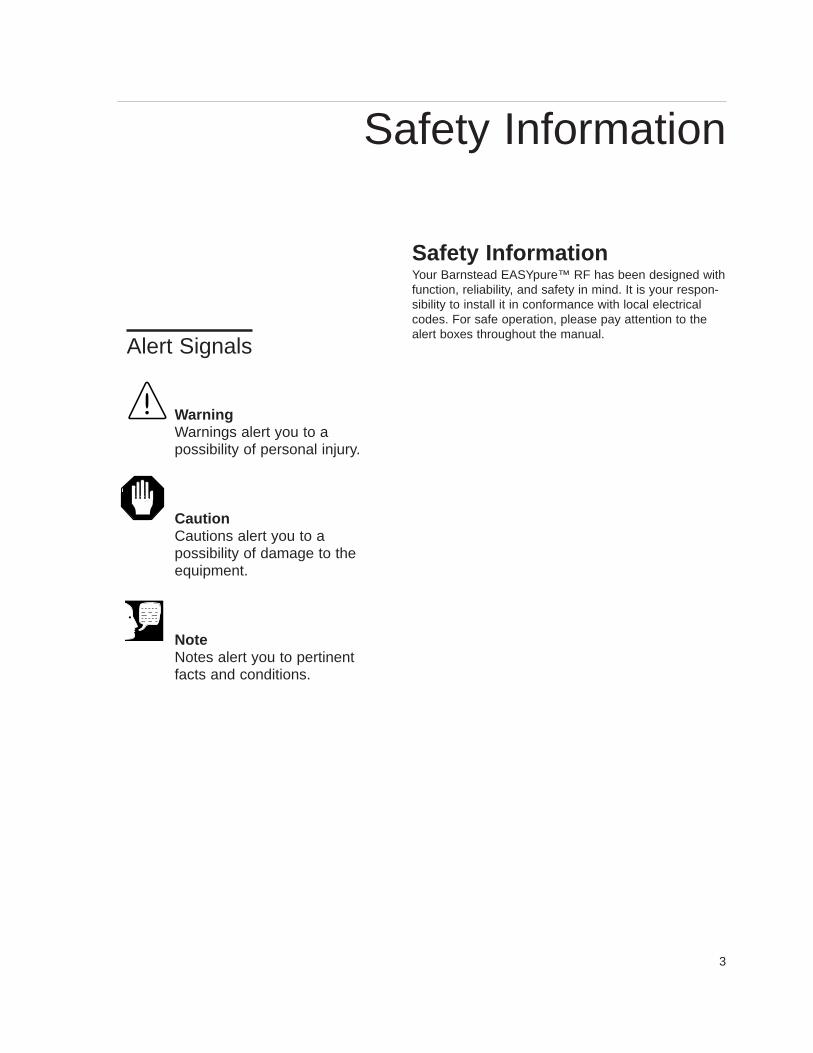
Safety InformationYour Barnstead EASYpure™ RF has been designed withfunction, reliability, and safety in mind. It is your respon-sibility to install it in conformance with local electricalcodes. For safe operation, please pay attention to thealert boxes throughout the manual.
WarningWarnings alert you to apossibility of personal injury.
CautionCautions alert you to apossibility of damage to theequipment.
NoteNotes alert you to pertinentfacts and conditions.
Alert Signals
Safety Information
4
WarningsWARNING
A. To avoid electrical shock, always:1. Use a properly grounded electrical outlet of correct voltage and current handling capacity.2. Do not place the EASYpure RF directly over equipment that requires electrical service. Routine main-
tenance of this unit may involve water spillage and subsequent electrical shock hazard if improperlylocated.
3. Replace fuses with those of the same type and rating.4. Do not disassemble water lines or remove cartridges where spilled water could contact equipment
that requires electrical service. Disassembly of water lines and removal of cartridges will result inwater spillage. Electrical shock hazard could result.
5. Disconnect from the power supply prior to maintenance and servicing.B. To avoid personal injury:
1. Do not use in the presence of flammable or combustible materials; fire or explosion may result. Thisdevice contains components which may ignite such materials.
2. This device is to be used with water feeds only. Sanitizing/cleaning agents must be used in compli-ance with instructions in this manual. Failure to comply with the above could result in explosion andpersonal injury.
3. Avoid splashing disinfecting solutions on clothing or skin. 4. Ensure all piping connections are tight to avoid chemical leakage. 5. Carefully follow manufacturer’s safety instructions on labels of chemical containers and material safe-
ty data sheets.6. Refer servicing to qualified personnel.
5
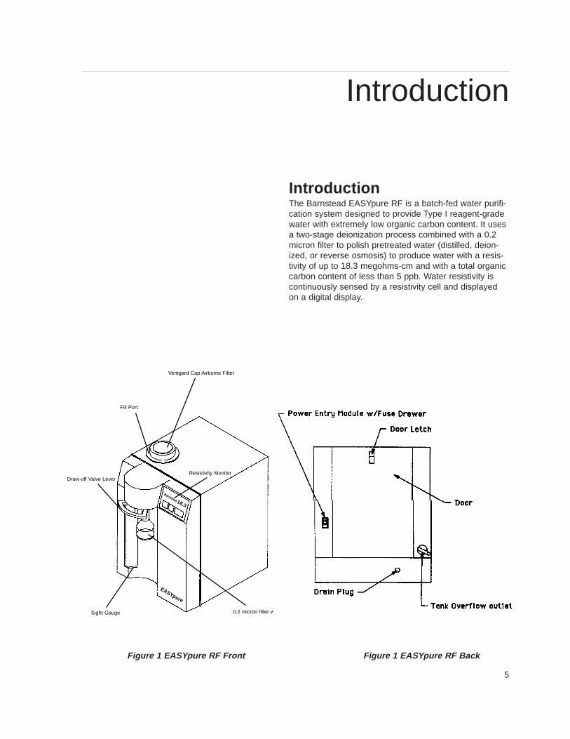
IntroductionThe Barnstead EASYpure RF is a batch-fed water purifi-cation system designed to provide Type I reagent-gradewater with extremely low organic carbon content. It usesa two-stage deionization process combined with a 0.2micron filter to polish pretreated water (distilled, deion-ized, or reverse osmosis) to produce water with a resis-tivity of up to 18.3 megohms-cm and with a total organiccarbon content of less than 5 ppb. Water resistivity iscontinuously sensed by a resistivity cell and displayedon a digital display.
Introduction
Figure 1 EASY pure RF Front Figure 1 EASY pure RF Back
EASYpure
18.3
Barnstead
Fill Port
Ventgard Cap Airborne Filter
Resistivity Monitor
0.2 micron filter w/bellSight Gauge
Draw-off Valve Lever
6
SpecificationsDimensions and Clearance requirements.EASYpure RF dimensions - 12" W X 19" D X 18 1/8" H (30.5 cm X 48.3 cm X 46.0 cm).
Clearances:Sides - 4" (10.1 cm) minimum to allow air flowAbove - 12" (30.5 cm) minimum for reservoir replenishment
Cartridge replacement requires that you be able to access the back of the unit and open the cartridgeaccess door (total depth, unit + open door, = 34") (86.4 cm).
Storage Reservoir Capacity - Approximately 6.5 liters usable, 7.0 liters total
Feedwater RequirementsThe EASYpure RF requires water pretreated by either distillation, deionization or reverse osmosis.
TOC - Less than 1.0 ppm.
Turbidity - Less than 1.0 N.T.U.
Temperature - 40°F - 120°F (4.4°C - 48.9°C)
Resistivity (Minimum):Distilled - 300,000 Ohm-cmDeionized - 1.0 Megohms-cmReverse osmosis - 100,000 Ohm-cm
Product W ater Quality
Resistivity: ASTM Type ITOC: Less than 5.0 PPB
Flow Rate: 0.5 LPM with a new final filter
Electrical RequirementsThe EASYpure RF is equipped with a power cord to be plugged into an electrical outlet of the appropriate volt-age.
Model D7032 - 100 VAC +5% -10%, 47-63 Hz.Model D7031 - 120 VAC +5% -10%, 47-63 Hz.Model D7033 - 240 VAC +5% -10%, 47-63 Hz.Model D7033-33 - 230 VAC +10% -10%, 47-63 Hz.
Environmental ConditionsOperating: 4°C - 49°C; 20% to 80% relative humidity, non-condensing. Installation Category II (over-voltage) in accordance with IEC 664. Pollution Degree 2 in accordance with IEC 664.
Altitude limit: 5,000 meters.Storage: -25°C to 65°C; 10% to 85% relative humidity.
Specifications
7
Declaration of Conformity (-33 models only)Barnstead|Thermolyne hereby declares under its sole re-sponsibility that this product conforms with the technicalrequirements of the following standards:
EMC: EN 50081-1 Generic Emission Standard;EN 50082-1 Generic Immunity Standard;
Safety: IEC 1010-1-92 Safety requirements forelectrical equipment for measurement, control and laboratory use; Part I: General Requirementsper the provisions of the Electromagnetic CompatabilityDirective 89/336/EEC, as amended by 92/31/EEC and93/68/EEC, and per the provisions of the Low VoltageDirective 73/23/EEC, as amended by 93/68/EEC.
The authorized representative located within the Europe-an Community is:
European ManagerBarnstead|ThermolyneSaabrückener Str. 248D-38116 BraunschweigGermany
Copies of the declaration of conformity are availableupon request.
SPECIFICATIONS
8
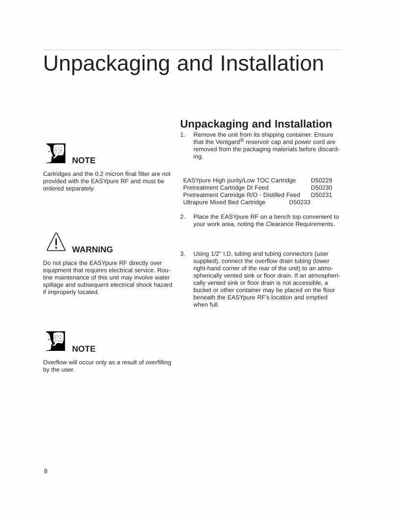
Unpackaging and Installation1. Remove the unit from its shipping container. Ensure
that the Ventgard® reservoir cap and power cord areremoved from the packaging materials before discard-ing.
EASYpure High purity/Low TOC Cartridge D50229 Pretreatment Cartridge DI Feed D50230Pretreatment Cartridge R/O - Distilled Feed D50231 Ultrapure Mixed Bed Cartridge D50233
2. Place the EASYpure RF on a bench top convenient toyour work area, noting the Clearance Requirements.
3. Using 1/2" I.D. tubing and tubing connectors (usersupplied), connect the overflow drain tubing (lowerright-hand corner of the rear of the unit) to an atmo-spherically vented sink or floor drain. If an atmospheri-cally vented sink or floor drain is not accessible, abucket or other container may be placed on the floorbeneath the EASYpure RF’s location and emptiedwhen full.
NOTE
Cartridges and the 0.2 micron final filter are notprovided with the EASYpure RF and must beordered separately.
WARNING
Do not place the EASYpure RF directly overequipment that requires electrical service. Rou-tine maintenance of this unit may involve waterspillage and subsequent electrical shock hazardif improperly located.
NOTE
Overflow will occur only as a result of overfillingby the user.
Unpackaging and Installation
9
UNPACKAGING AND INSTALLA TION
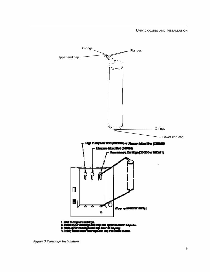
Figure 3 Cartridge Installation
O-rings
Upper end cap
Flanges
O-rings
Lower end cap
10
Initial OperationCartridge Installation1. Open cartridge access door in the rear of the unit by
pushing the door latch down.
2. Remove a new Pretreatment cartridge (part numberD50230 or D50231) from its plastic bag.
3. Wet the o-rings on both end caps.
4. Press the upper end cap into the upper right positionuntil it bottoms out.
5. Lower the cartridge and insert the lower end cap intothe lower socket until it is firmly seated.
6. Repeat steps 1 - 5 with the EASYpure High Purity/LowTOC or Ultrapure cartridge, placing it in the left-handposition.
7. Close cartridge access door.
Storage Reservoir Filling and Cartridge RinseUp
To fill the reservoir:
1. Remove the molded plastic Ventgard cap.
2. Carefully pour pretreated feedwater into the reservoiruntil the water is level with the top of the sight gaugeon the front of the unit. Replace the Ventgard cap.
3. Plug power cord into the power entry module on theleft-hand side of the rear of the unit and plug into alive outlet. Turn on power entry module switch.
4. Press “START” and open draw-off valve.5. Rinse one complete reservoir volume of water through
the cartridges to drain.
6. Remove a new 0.2 micron filter and bell assemblyfrom its bag and insert it into the Luer fitting. Gentlyturn it clockwise until it is fully seated in the Luer fit-ting.
7. Refill the reservoir with pretreated water.
8. Flush second reservoir volume of water through the fil-ter.
NOTE
The upper end cap is the one with the right-an-gle turn and the two flanges. The lower end capextends straight out from the cartridge. (SeeFigure 3.)
NOTE
The two flanges on the end cap should be ableto slide down on each side of the keyway wall.
NOTE
Cartridge rinse up procedure must be followedafter each cartridge and/or filter replacement.
NOTE
In the event that you overfill the feedwater res-ervoir, allow the excess water to drain from thereservoir through the overflow drain tubing be-fore replacing the Ventgard cap. This will pre-vent wetting the filter element.
Initial Operation
11
Normal Operation1. Fill the feedwater reservoir with water and replace
the cap.
2. Turn main power on at power entry module.
3. Press the “START” button on the front of theEASYpure RF.
The EASYpure RF’s pump will begin to run and thePurity meter will display the resistivity of the water inmegohm-cm.
4. Allow the water’s resistivity to rise to the desiredpurity before drawing off water.
Water Draw off1. Remove the protective cap from the filter bell.
2. Depress the draw-off lever.
3. When draw off is complete, lift the draw-off leverand replace the protective cap on the filter bell.
Feedwater ReplenishmentAs water is drawn-off from the EASYpure RF, the feed-water reservoir will require refilling. To refill the reservoir:
1. Remove the Ventgard cap. Do not allow water toenter the Ventgard cap.
2. Pour pretreated feedwater into the feedwater reser-voir until the water is level with the top of the sightgauge.
3. Replace the Ventgard cap.
4. Allow the water’s resistivity to rise to the desiredpurity before drawing off water.
NOTE
For more demanding applications where low TOCwater is required, a third reservoir volume rinse ofthe cartridges and filter may be necessary.
NOTE
On initial startup, the purity meter may display“ERR.” This is caused by air in the cell and shouldbe replaced by a resistivity reading almost imme-diately. If “ERR” does not go out after the pumphas run for a minute or if it appears any time whilethe EASYpure RF is in operation, refer to theTroubleshooting section of this manual.
Normal Operation
12
Run and Standby ModesSince not all qualities of permissible feedwater will reachmaximum resistivity after one pass through the unit’s car-tridges (especially as the cartridges near exhaustion), theEASYpure RF has two operational modes.
In the run mode, the pump continuously recirculates waterthrough the cartridges. This is the mode that the unit entersupon startup. If water will be drawn from the EASYpure RFon a continuous basis throughout the day, it is recommend-ed that the EASYpure RF be left in the run mode. This willensure that the feedwater added to refill the EASYpureRF’s reservoir will be up to maximum purity when it isneeded. In the run mode, the purity meter display indicatesthe resistivity of the water available for draw off.
In standby mode, the pump runs for 10 minutes out ofevery hour (i.e. ten minutes on, fifty minutes off). If waterwill be drawn from the unit only infrequently, it is recom-mended that the unit be put into standby mode. To put theunit into standby mode, press the “STANDBY” button onthe front of the unit. The purity meter’s digital display willdisplay “Sby” to indicate that the unit is in standby mode.
NORMAL OPERATION
13
Maintenance and Servicing
Cartridge Replacement (See Figure 3, page 9)The frequency with which you will need to replace car-tridges is dependent on your feedwater’s characteristicsand your purity requirements. Replace the cartridgeswhen the product water purity drops below acceptablelevels of resistivity or when organic levels become toohigh.
Cartridge Removal1. Disconnect the unit from the power supply.
2. Open the cartridge access door in the rear of theunit by sliding the latch down and pulling the doortoward you. The door will swing down.
3. Grasp one of the cartridges at the bottom and pull itstraight up to disconnect the lower end cap fromthe lower socket.
4 Move cartridge upward until upper socket is in key-hole of keyway. (See Figure 3.)
5. Pull cartridge straight out from unit to disconnectupper end cap from upper socket.
6. Repeat steps 3 - 5 with the other cartridge.
7. Discard the used cartridges. (See note below.)
8. Install new cartridges and rinse according to the in-structions for Cartridge Installation in the InitialOperation section (page 8).
0.2 Micron Filter ReplacementReplace the 0.2 micron filter whenever any of the follow-ing conditions occur: every 30 days, the product waterflow rate is reduced or bacteria break through. The 0.2micron filter is shipped assembled with a bell. To replacethe 0.2 micron filter assembly:1. Remove the old 0.2 micron filter assembly by turn-
ing it counter-clockwise until it is free from the Luerfitting.
WARNING
Disconnect from the power supply prior to main-tenance and servicing.
Disassembly of water lines and removal of car-tridges will result in water spillage. Do not per-form these operations where spilled water couldcontact equipment that requires electrical service.Electrical shock hazard could result.
Refer servicing to qualified personnel.
NOTE
The cartridges will still contain water when re-moved. Therefore, you will want to have a sink,bucket or other waterproof container available toplace them in after removal.
NOTE
A small amount of water will drain from the car-tridge when it is disconnected from the lowersocket. Plug the cartridge’s lower opening withyour finger to minimize water spillage while youfinish removing the cartridge.
NOTE
Used cartridges may be recycled. See P.U.R.E. in-formation packed with new cartridges.
Maintenance and Servicing
14
2. Remove the new 0.2 micron filter assembly from itsbag and insert it into the Luer fitting. Gently turn itclockwise until it is fully seated in the the Luer fitting.
3. Rinse at least one reservoir volume of water throughthe filter to drain prior to using the product water.
Ventgard Cap ReplacementThe purifying media and filter in the Ventgard filter elementhave a limited capacity. Therefore, the Ventgard cap shouldbe replaced every 90 days. The Ventgard cap is shipped asa complete unit; replacement involves simply removing thenew Ventgard cap from its plastic storage bag and placingit on the reservoir. A Ventgard cap can be stored in a cool,dry place almost indefinitely, provided its plastic storagebag has not been opened.
General Cleaning InstructionsWipe exterior surfaces with a lightly dampened cloth con-taining mild soap solution.
System SanitizationFrequency of cleaning is difficult to determine because ofvariability in feedwater and usage. Cleaning is necessarywhen residual deposits are evident inside the feedwaterreservoir or if a new 0.2 micron filter clogs rapidly after in-stallation even though the cartridges were properly rinsedbefore the 0.2 micron filter was installed. To sanitize theEASYpure RF, the 0.2 micron final filter and the purificationcartridges must be removed. The purification cartridgesmust be replaced with empty cartridges. These must be or-dered separately. Contact Barnstead|Thermolyne and orderpart number D7034.
1. Drain the system.a. Place the filter over a sink or place a bucket or
other suitable large container under the filter anddraw off water as described under Water Drawoff in the Operation section of this manual.Draw off water until the water level in the feed-water reservoir is lowered to the point that thepump protector switch disables the pump. Liftdraw-off valve to closed position.
b. Disconnect the unit from the power supply.
CAUTION
Do not overtighten the 0.2 micron filter assem-bly onto the Luer fitting or use excessive forcein seating it. The filter and/or Luer fitting can bedamaged by overtightening or excessive force.
NOTE
If a newly installed 0.2 micron filter clogs rapidlyafter installation, the EASYpure RF may need tobe sanitized to remove bacterial contaminants.See System Sanitization , page 14.
MAINTENANCE AND SERVICING
15
c. Turn the unit around to provide access to thedrain plug on the lower edge of the backpanel.
d. Place the drain plug over a sink, or place abucket or other suitable large container underthe drain plug. Remove the drain plug by turn-ing it while pulling until it comes out.
e. Drain remaining water from the reservoir andsystem.
f. Replace the drain plug, taking care to fully in-sert it into the drain tubing.
g. Remove cartridges and filter and install emptycartridge tubes (part number D7034) accord-ing to the instructions in CartridgeReplacement (page 10).
2. Remove Ventgard cap and pour 6 liters of pretreat-ed feedwater into reservoir.
3. Add 10ml to 20ml of household chlorine bleach(5.25% sodium hypochlorite) to reservoir.
4. Connect the unit to the power supply. Press the“START” button to turn unit on.
5. Allow the unit to recirculate the disinfecting solutionfor thirty minutes. Cycle the draw-off valve to sani-tize the valve.
6. Drain the system as described in step 1 of this sec-tion.
7. Refill the feedwater reservoir with feedwater and re-circulate the water through the system for ten min-utes.
8. Drain the system as described in step 1 of this sec-tion.
9. Remove the empty cartridge tubes according to theinstructions in the Cartridge Removal section.Drain and retain the empty cartridge tubes forfuture use.
NOTE
Drain plug is not attached to unit; use care whenremoving it over an open drain to avoid dropping itinto the drain.
WARNING
Avoid splashing disinfecting solutions on clothingor skin.
Ensure all piping connections are tight to avoidchemical leakage.
Ensure that overflow drain tubing is directed todrain to avoid chemical leakage during disinfect-ing.
Ensure adequate ventilation.
Carefully follow manufacturer’s safety instructionson labels of chemical containers and materialsafety data sheets.
MAINTENANCE AND SERVICING
16
10. Install and rinse new cartridges according to the in-structions in the Cartridge Installation section. Donot reinstall used cartridges or 0.2 micron filter (theymay contain large amounts of bacteria.)
11. Reconnect to the power supply and press the“START” button.
Fuse Replacement1. Disconnect the EASYpure RF from the power supply
and remove the reservoir and cap assembly.
2. Remove the power cord from the power entry module.
3. Remove the screws securing the EASYpure RF’s cov-er.
4. Remove the cover by lifting it straight up.
5. Pull out the fuse drawer located in the power entrymodule on the back left-hand side of the unit.
6. Remove old fuses and replace with fuses of the sametype and rating. (See Parts Listing, page 18.)
7. Replace fuse drawer.
8. Replace cover and power cord and reservoir cap as-sembly.
9. Reconnect unit to power supply.
Printed Circuit Board Replacement (See Fig -ure 6)1. Disconnect the unit from the power supply.
2. Remove the power cord from the power entry module.
3. Remove the reservoir cap and the screws securingthe EASYpure RF’s cover.
4. Remove the cover by lifting it straight up.
5. The filter and the Luer fitting.
6. Remove the screws securing the front cover. Removethe front cover.
MAINTENANCE AND SERVICING
17
7. Disconnect the membrane switch lead from theprinted circuit board. (See Figure 6.)
8. Disconnect the resistivity cell lead from the printedcircuit board.
9. Disconnect the printed circuit board relay plug bysqueezing the retaining clip while pulling the plugstraight out from the frame.
10. Remove the nuts holding the printed circuit board inplace.
11. Remove the printed circuit board. Disconnect powersupply (3 wires) from printed circuit board.
12. Reconnect power supply to new printed circuitboard and install the new printed circuit board.Refer to electrical diagrams.
13. Reconnect the resistivity cell lead and printed circuitboard relay plug.
14. Reconnect the membrane switch lead.
15. Reinstall the front cover.
16. Retape the Luer fitting with new Teflon® tape andreinstall fitting.
17. Reinstall the EASYpure RF’s cover.
18. Reconnect the power cord to the unit and the unitto the power supply.
MAINTENANCE AND SERVICING
18
Cleaning the Resistivity Cell1. Disconnect the unit from the power supply.
2. Remove the power cord from the power entry module.
3. Remove the reservoir cap and the screws securingthe EASYpure RF’s cover.
4. Remove the cover by lifting it straight up. Remove thefilter and Luer fitting. Remove the front cover.
5. Remove the screw holding the cell-cable retaining clip.6. Disconnect the cell lead from the printed circuit board
and gently pull the cable out of the EASYpure RF’sframe.
7. Unscrew and remove the cell.
8. Carefully remove the O-ring before cleaning the cell.Remove the cell bushing.
9. Wash the cell in a mild detergent solution or a 10%Hydrochloric or Sulfuric acid solution (follow acid man-ufacturers recommended handling procedure). Thismay be done in an ultrasonic cleaner or with a softbrush.
10. Thoroughly rinse the cell in deionized or distilled waterfollowing the detergent or acid cleaning.
11. After cleaning, reinstall and check the o-ring on cell;replace if necessary.
12. Reinstall the cell into the cell well and hand tighten.Reroute the cable up through the housing and recon-nect. Refer to Figure 6 for proper position.
CAUTION
The cell electrodes are etched to improve wet-ting characteristics. Do not mechanically abradeor damage this surface (i.e. do not clean with awire brush, sandpaper, etc.).
CAUTION
Do not immerse the entire cell assembly incleaning solution, only the electrode portion.
MAINTENANCE AND SERVICING
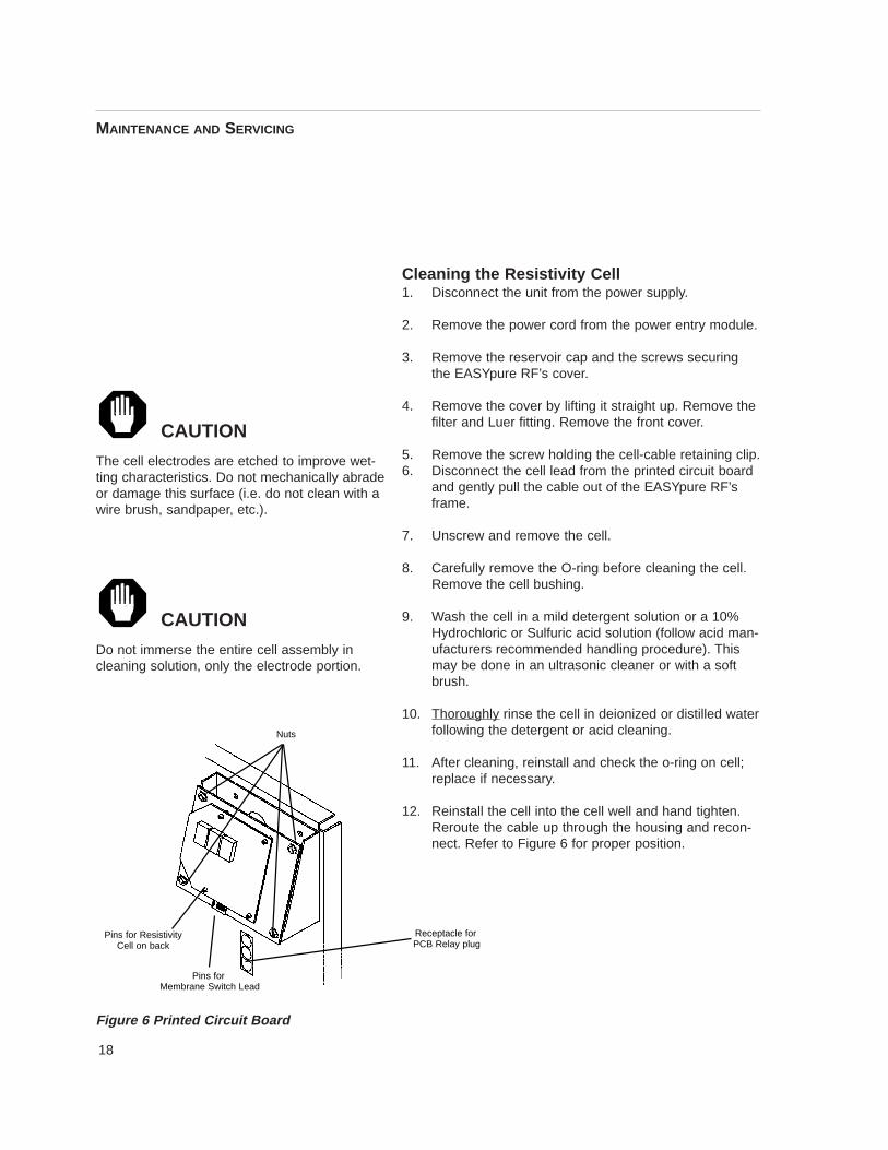
Figure 6 Printed Circuit Board
Pins for ResistivityCell on back
Pins forMembrane Switch Lead
Receptacle for PCB Relay plug
Nuts
19
13. Reinstall the screw holding the cell-cable retainingclip. Replace the front cover. Retape the Luer fittingwith new Teflon® tape and reinstall fitting. Replacethe top cover.
14. Reconnect the power cord to the unit and the unitto the power supply.
ShutdownIf the EASYpure RF is to be shut down for an extendedperiod of time, the unit should be completely drained andthe cartridges removed to prevent the growth of bacteria.
If the system has remained inactive and full of water,then the unit should be drained, sanitized and new car-tridges installed prior to use.
MAINTENANCE AND SERVICING

20
TroubleshootingProblem Possible Causes Solutions
EASYpure RF completely No electrical power to Ensure that the EASYpure RFinactive. (pump not operating, EASYpure RF. power cord is connectedcontrol panel not lit, etc.). to a live power source and
completely plugged into electrical outlet.
Make sure power entry module switch is on.
Fuses blown. Replace the fuses as indicatedin the Fuse Replacement section (page 13).
Pump runs, but no display Main PCB and display PCB Disconnect unit from power. (no digital display). not connected. Check and reconnect boards.
Pump does not run. Display lit. Low water level in feedwater Replenish feedwater.reservoir.
Pump worn out or defective. Replace pump.
Display reads “Err” when Resistivity cell lead Check resistivity cell lead.checking resistivity. disconnected.
Air in system. Purge air from system by drawingoff water according to the instructions in theOperation section (page 9).
Resistivity cell dirty. Clean cell and reinstall (page 15).
Recirculated water will not Exhausted cartridge. Replace the cartridges as indicated in the rinse up to desired purity level. Cartridge Replacement section (page 10)
Cartridges out of order. Install the cartridges in the proper orderas indicated In the Cartridge Installation section (page 8).
Reduced or no product flow 0.2 micron final filter clogged. Replace the 0.2 filter assemblyfrom the 0.2 filter assembly. as indicated in the 0.2 Micron
Filter Replacement section (page 11).
Troubleshooting
21
Problem Possible Causes Solutions
0.2 micron final filter clogs DI Pretreatment cartridge Rinse up DI Pretreatment cartridge as rapidly after replacement. (Part Number D50230) not described in Cartridge Rinse-up
properly rinsed up before use. Procedures on page 8. Replace the0.2 filter assembly as indicatedin the 0.2 Micron Filter Replacementsection (page 11).
EASYpure RF contaminated with Sanitize EASYpure RF according to bacteria. the instructions in System
Sanitization on page 12. Replace the 0.2 filter assembly as indicated in the 0.2 Micron Filter Replacement section (pages 11).
Short cartridge life. Cartridges being used are beyond Check the expiration date. Cartridges expiration date. begin to lose capacity after being
stored two years from the date of manufacture. Replacethe cartridges with unexpired ones.
Change in feedwater characteristics. If a Barnstead ROpure is the feedwater source, check that the membrane is functioning properly.
If a Barnstead Still is the feedwater source, ensure that the distillatetemperature does not exceed 120°F when added to the EASYpure RF feedwater reservoir.
If feedwater is from a central water purification system, verify water quality and proper functioning of the system.
Water leakage inside Water spillage during reservoir Use greater care when pouringEASYpure RF. replenishment. into reservoir.
Cartridge connecting tubing not Press connecting tubingfully seated into sockets. firmly into sockets.
Missing or defective O-rings. Install or replace O-rings.
TROUBLESHOOTING
22
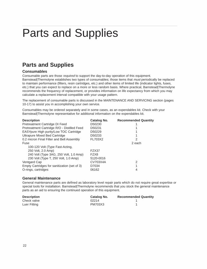
Parts and SuppliesConsumablesConsumable parts are those required to support the day-to-day operation of this equipment.Barnstead|Thermolyne establishes two types of consumables; those items that must periodically be replacedto maintain performance (filters, resin cartridges, etc.) and other items of limited life (indicator lights, fuses,etc.) that you can expect to replace on a more or less random basis. Where practical, Barnstead|Thermolynerecommends the frequency of replacement, or provides information on life expectancy from which you maycalculate a replacement interval compatible with your usage pattern.
The replacement of consumable parts is discussed in the MAINTENANCE AND SERVICING section (pages10-17) to assist you in accomplishing your own service.
Consumables may be ordered separately and in some cases, as an expendables kit. Check with yourBarnstead|Thermolyne representative for additional information on the expendables kit.
Description Catalog No. Recommended QuantityPretreatment Cartridge DI Feed D50230 1Pretreatment Cartridge R/O - Distilled Feed D50231 1EASYpure High purity/Low TOC Cartridge D50229 1Ultrapure Mixed Bed Cartridge D50233 10.2 micron Final Filter and Bell Assembly FL703X2 2Fuse 2 each
100-120 Volt (Type Fast-Acting,250 Volt, 2.0 Amp) FZX37240 Volt (Type 3AG, 250 Volt, 1.0 Amp) FZX8230 Volt (Type T, 250 Volt, 1.0 Amp) 5120-0016
Ventgard Cap CV703X4A 2Empty Cartridges for sanitization (set of 3) D7034 1O-rings, cartridges 06162 4
General MaintenanceGeneral maintenance parts are defined as laboratory level repair parts which do not require great expertise orspecial tools for installation. Barnstead|Thermolyne recommends that you stock the general maintenanceparts as an aid to ensuring the continued operation of this equipment.
Description Catalog No. Recommended QuantityCheck valve 02214 1Luer Fitting PM703X3 1
Parts and Supplies
23
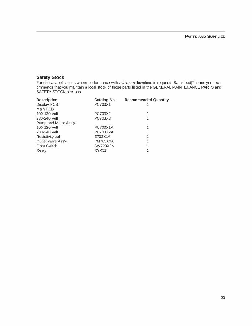
Safety StockFor critical applications where performance with minimum downtime is required, Barnstead|Thermolyne rec-ommends that you maintain a local stock of those parts listed in the GENERAL MAINTENANCE PARTS andSAFETY STOCK sections.
Description Catalog No. Recommended QuantityDisplay PCB PC703X1 1Main PCB100-120 Volt PC703X2 1230-240 Volt PC703X3 1Pump and Motor Ass’y100-120 Volt PU703X1A 1230-240 Volt PU703X2A 1Resistivity cell E703X1A 1Outlet valve Ass’y. PM703X9A 1Float Switch SW703X2A 1Relay RYX51 1
PARTS AND SUPPLIES
24
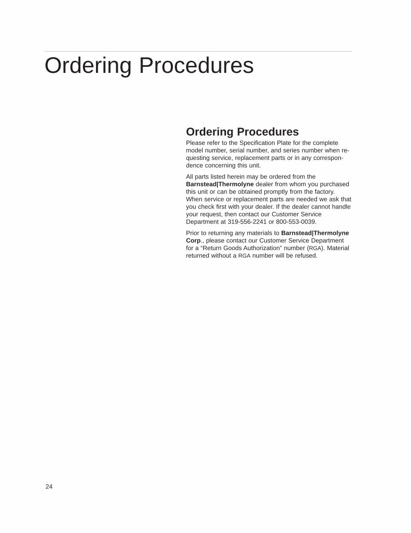
Ordering ProceduresPlease refer to the Specification Plate for the completemodel number, serial number, and series number when re-questing service, replacement parts or in any correspon-dence concerning this unit.
All parts listed herein may be ordered from theBarnstead|Thermolyne dealer from whom you purchasedthis unit or can be obtained promptly from the factory.When service or replacement parts are needed we ask thatyou check first with your dealer. If the dealer cannot handleyour request, then contact our Customer ServiceDepartment at 319-556-2241 or 800-553-0039.
Prior to returning any materials to Barnstead|ThermolyneCorp ., please contact our Customer Service Departmentfor a “Return Goods Authorization” number (RGA). Materialreturned without a RGA number will be refused.
Ordering Procedures
25
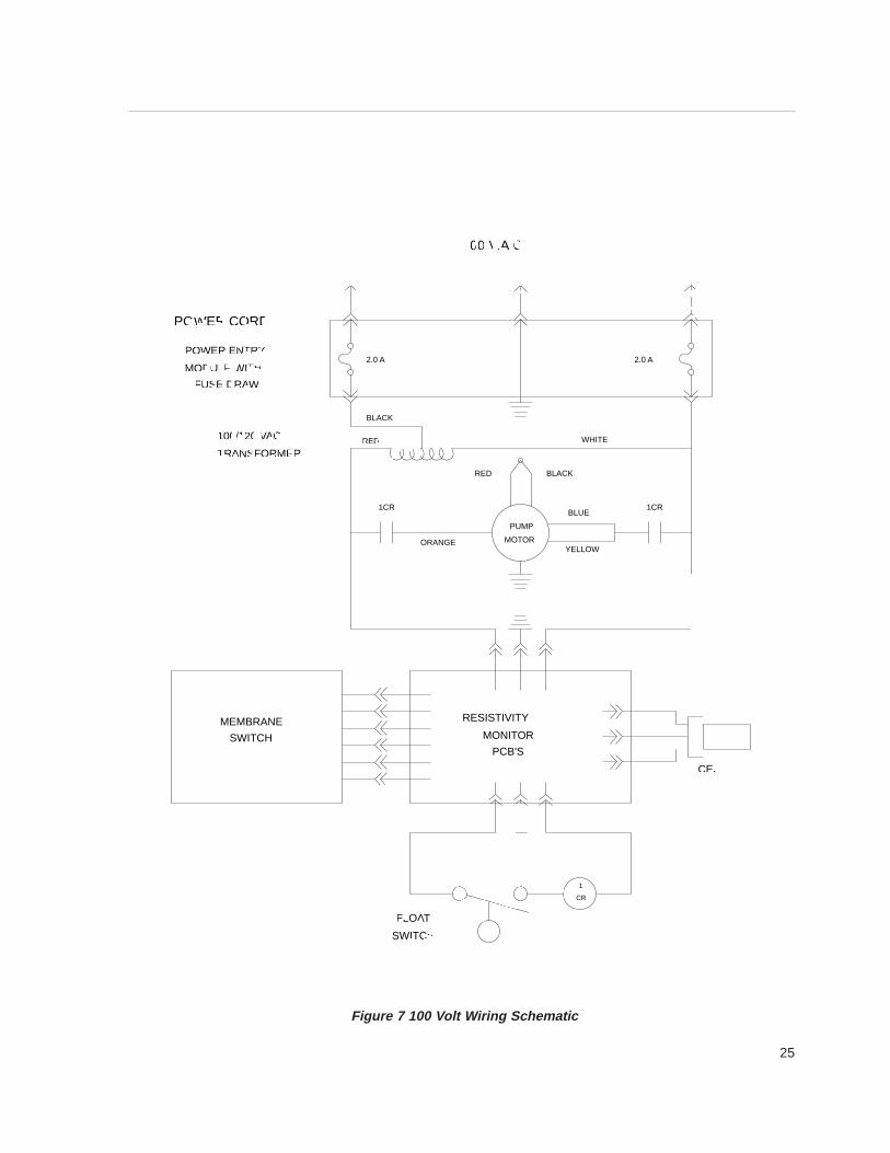
Figure 7 100 V olt W iring Schematic
1
CR
MEMBRANE
SWITCH
ORANGEYELLOW
PUMP
MOTOR
RED BLACK
1CR 1CR
2.0 A 2.0 A
RESISTIVITY
MONITOR
PCB'S
SWITCH
FLOAT
CELL
100 V.A.C.
BLUE
POWER CORD
POWER ENTRY
MODULE WITH
FUSE DRAW
WHITERED
BLACK
100/120 VAC
TRANSFORMER
26
1
CR
MEMBRANE
SWITCH
ORANGEYELLOW
PUMP
MOTOR
RED BLACK
1CR 1CR
2.0 A 2.0 A
RESISTIVITY
MONITOR
PCB'S
SWITCH
FLOAT
CELL
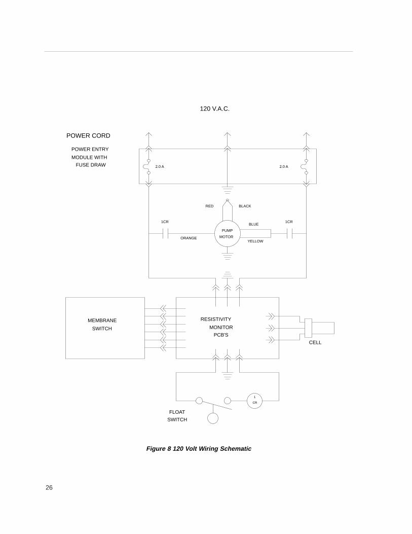
120 V.A.C.
BLUE
POWER CORD
POWER ENTRY
MODULE WITH
FUSE DRAW
Figure 8 120 V olt W iring Schematic

27
1
CR
MEMBRANE
SWITCH
ORANGE YELLOW
PUMP
MOTOR
RED BLUE
1CR 1CR
BLACK
1.0 A 1.0 A
RESISTIVITY
MONITOR
PCB'S
SWITCH
FLOAT
CELL
230 V.A.C.
POWER CORD
POWER ENTRY
MODULE WITH
FUSE DRAW
Figure 9 230/240 V olt W iring Schematic

® Registered trademark of DuPont.
Barnstead|Thermolyne Corporation warrants that if a product manufactured byBarnstead|Thermolyne and sold by it within the continental United States or Canadaproves to be defective in material or construction, it will provide you, without charge, for aperiod of ninety (90) days, the labor, and a period of one (1) year, the parts, necessary toremedy any such defect. Outside the continental United States and Canada, the warrantyprovides, for one (1) year, the parts necessary to remedy any such defect. The warrantyperiod shall commence either six (6) months following the date the product is sold byBarnstead|Thermolyne or on the date it is purchased by the original retail consumer,whichever date occurs first.
All warranty inspections and repairs must be performed by and parts obtained froman authorized Barnstead|Thermolyne dealer or Barnstead|Thermolyne (at its own dis -cretion) . Heating elements, however, because of their susceptibility to overheating and con-tamination, must be returned to our factory, and if, upon inspection, it is concluded that fail-ure is not due to excessive high temperature or contamination, warranty replacement will beprovided by Barnstead|Thermolyne . The name of the authorized Barnstead|Thermolynedealer nearest you may be obtained by calling 1-800-446-6060 or writing to:
Barnstead|ThermolyneP.O. Box 797
2555 Kerper BoulevardDubuque, IA 52004-0797
USAFAX: (319) 589-0516
E-Mail: [email protected]|Thermolyne’ s sole obligation with respect to its product shall be to repair
or replace the product. Under no circumstances shall it be liable for incidental or conse-quential damage.
THE WARRANTY STATED HEREIN IS THE SOLE WARRANTY APPLICABLE TOBarnstead|Thermolyne PRODUCTS. Barnstead|Thermolyne EXPRESSLY DISCLAIMSANY AND ALL OTHER WARRANTIES, EXPRESSED OR IMPLIED, INCLUDING WAR-RANTIES OF MERCHANTABILITY OR FITNESS FOR USE.
One Year Limited Warranty
Barnstead Thermolyne2555 Kerper Blvd.P.O. Box 797Dubuque, IA 52004-0797 USAPHONE: 319-556-2241 • 800-553-0039FAX: 319-589-0516E-Mail: [email protected]
a subsidiary of