barrier design guide - wganz.org.nz
TRANSCRIPT

Barrier Design
Guide November 2020
This document has been prepared by the Glass Technical Committee of the Window & Glass Association of New Zealand and is intended to update the glazing specific information published in the DBH Guidance on Barrier Design dated March 2012.
WGANZ Barrier Design Guide
V2.2 -November 2020 Page 2
Contents 1.0 Scope and Definitions 3
2.0 Guidance and the Building Code 7
3.0 Design Criteria 9
4.0 Materials 38
Glass 38
Timber 56
Metals 60
5.0 Checklist 65
Structure - B1
Durability - B2
Access routes - D1
External moisture - E2
Hazardous building materials - F2
Safety from falling - F4

WGANZ Barrier Design Guide
V2.2 -November 2020 Page 3
1.0 Scope and Definitions
1.1 Scope
This document brings together relevant information required for designers, manufacturers, and installers of barriers. It explains ways to design and install New Zealand Building Code (NZBC) compliant barriers and provides recommendations for the design and construction of permanent barriers that are required in and around buildings.
This guide is applicable to:
• barriers to decks, stairs, and landings, • walls, glazing (including screens and full-height glazing), fences, and other
elements of buildings where these elements prevent a fall of one metre or more.
It is advisable to apply the recommendations included in this guide to all building elements protecting a fall, although the NZBC does not require a barrier where the fall is less than one metre. Refer to Determination 2008/081 for further information. Where barriers are installed in instances where the fall is less than one metre, certain NZBC requirements will still apply, e.g. Clause F2 Hazardous Building Materials.
This guide is not applicable to:
• barriers intended to stop or divert moving vehicles, • barriers used in building work and construction, • swimming pool fences safeguarding against a fall of less than one metre, • barriers on walking tracks and bridges on walking tracks etc.
While this document is intended primarily for use by designers, sections on maintenance contain information beneficial to owners.

WGANZ Barrier Design Guide
V2.2 -November 2020 Page 4
1.2 Definitions
For the purposes of this guide the following definitions apply. See also Figure 1.1
Baluster Vertical members at close centres acting as the infill to a barrier.
Note: Balusters should not be confused with Structural Posts which are used in post and rail barrier systems.
Balustrade A balustrade is a row of balusters or other infill. Note: A ‘balustrade’ is the commonly used term for a barrier.
Barrier Any building element intended to prevent a person from falling and to retain, stop or guide a person.
Boundary joist(s) A joist running along the outer ends of the floor joists. Decking The material forming the walking surface of a floor or deck supported by
joists. Edge joist(s) A member or members at the perimeter (end) of a floor or deck running
parallel to other joists. Handrail A rail to provide support to, or assist with, the movement of a person.
Note: Where the handrail is used in an accessible route refer to paragraph 6.0 of Acceptable Solution D1/AS1 and Determination 2017-009
Infill The building element (e.g. wires, rail, mesh, safety glass or other solid
panel, louvres, balusters) spanning between supporting structure, posts or rails.
Rail A member used as a handrail, top rail, bottom rail or top edge interlinking
rail or capping in a barrier system. Bottom rail The lower rail supporting the barrier infill
Handrail A rail to provide support to or assist the movement of a person Note: Where the handrail is used in an accessible route refer to paragraph 6 of D1/AS1.
Interlinking rail A rail (normally used with cantilevered frameless glass barriers) that is connected to each glass pane or to a structural post or other building element. Note: In the event a glass panel is broken, an interlinking rail spans the broken pane at the required barrier height and shall resist the serviceability limit state (SLS) line and concentrated loads. Interlinking rails may be fitted 100mm or less below the required barrier height as an Alternative Solution, subject to the approval of the Building Consent Authority.

WGANZ Barrier Design Guide
V2.2 -November 2020 Page 5
Load-supporting rail A rail that is mechanically fixed to the structure, structural posts, or infill, that supports the applied ultimate limit state (ULS) design loads. Note: Also known as a structural handrail and they are normally interlinking.
Non-load-supporting rail A rail (normally used with glass barriers on the top edge of the glass) that does not carry the design loads alone but relies on the glass to support the design loads. Note: Non-load-supporting rails may be interlinking.
Top rail The upper rail supporting the barrier infill which may also act as a handrail. Safety glass Any material complying with section 1.6 NZS4223.3:2016 Human Impact Safety
Requirements. Stiff interlayer An interlayer that complies with NZ Building Code Acceptable Solution B1/AS1
clause 7.3.1 c). Interlinking rails are not required for a heat-strengthened or toughened laminated structural safety glass barrier that has a stiff interlayer that when both panes of the laminate are fractured, resist 0.2kN concentrated load and not deflect more that 250mm.
Structural post A building element providing support for combinations of handrail, top and bottom
rails, and infill of a barrier.

WGANZ Barrier Design Guide
V2.2 -November 2020 Page 6
Figure 1.1: Barrier elements
Figure 1.2: Handrail/top rail for timber barriers

WGANZ Barrier Design Guide
V2.2 -November 2020 Page 7
2.0 Guidance and the NZ Building Code
The aim of this document is to provide guidance on how the relevant Building Code performance criteria can be achieved for barriers.
Barriers are required to meet the performance criteria described in the Building Code. The relevant Building Code clauses for barriers are:
• B1 Structure
• B2 Durability
• D1 Access routes
• E2 External moisture
• F2 Hazardous building materials
• F4 Safety from falling
Some of these clauses may not apply for all installations. For example, Clause F2 Hazardous building materials, may not always apply because some barrier installations will not involve the use of hazardous building materials such as glass. The objectives of each of these Building Code clauses are summarised in Table 2.1:
Table 2.1: Relevant Building Code clauses Clause Summarised objectives
B1 Structure
Protect people from injury or loss of amenity and protect other property from damage caused by structural failure.
B2 Durability
Ensure that throughout a building’s life it will satisfy the other objectives of the Building Code
D1 Access routes
Safeguard people from injury during movement into, within and out of buildings.
E2 External moisture
Protect people from illness caused by external moisture entering the building.
F2 Hazardous building material
Protect people from illness or injury and other property from damage caused by exposure to hazardous building materials.
F4 Safety from falling
Safeguard people from injury caused by falling.
The Building Act 2004 and the Building Code form the mandatory parts of the building controls regime. The Department’s Acceptable Solutions and Verification Methods describe methods

WGANZ Barrier Design Guide
V2.2 -November 2020 Page 8
to comply with the performance criteria of the Building Code. Other ways may also be used to demonstrate compliance with the Building Code. Barriers can be designed, manufactured, and installed by using the Department’s Verification Methods and Acceptable Solutions. However, it should be noted that Acceptable Solutions and Verification Methods:
• are not mandatory • must be used within their scopes and limits • are generic and do not include proprietary systems or products • can be conservative because they are deemed to always comply with the Building
Code • and at times only describe one way to demonstrate compliance with the Building
Code.
Not everyone wants a “one size fits all” building solution. A building owner may want something that looks different or performs better, is more cost effective, or overcomes a specific site problem. Whatever the reason, a non-generic approach to barrier design and construction may often be required. This guidance predominately offers advice on how best to use the Acceptable Solutions and Verification Methods to achieve NZBC compliant barriers. However, in areas where the Acceptable Solutions and Verification Methods are limited, or even silent, this guidance offers additional information and advice on how to achieve NZBC compliant barriers. This will give designers and manufacturers the freedom to propose innovative solutions that provide the best outcome for each project but still meet the requirements of the Building Code. Refer to the Department’s website www.building.govt.nz for further guidance on the use of Alternative Solutions. This document helps set out what information and evidence the designer should provide to the Building Consent Authority (BCA) as part of a building consent application submitted by the owner.

WGANZ Barrier Design Guide
V2.2 -November 2020 Page 9
3.0 Design Criteria
3.1 Introduction
Barriers must be designed to resist the loads (such as imposed and wind loads) they are likely to experience throughout their lives without collapsing or becoming unstable (see section 3.4) and without deflecting unacceptably, causing a loss of amenity (see section 3.5). The barrier must also be sufficiently durable, without the need for reconstruction or major renovation, to function as required throughout its life (see section 3.8).
3.2 Design procedures
Barriers should be designed in accordance with the relevant clauses in the appropriate New Zealand materials Standards using the loads given in the Standard series AS/NZS 1170. It is important that the design procedure takes account of the relevant aspects of durability, geometry, occupancy, strength, and amenity to ensure the final design meets the requirements of the New Zealand Building Code. The design procedure for a typical barrier is set out in Figure 3.1. When the barrier solution incorporates a proprietary balustrade system, a number of the steps in the design procedure should already have been undertaken by the manufacturer of the balustrade system. In these instances, the design effort should focus on ensuring that:
• the durability requirements of the specific application are met by the proprietary
balustrade system, and • the supporting structure is capable of accommodating the loads applied to the
balustrade system without collapsing or excessive deflection.
The supplier of the proprietary balustrade system must provide evidence that the balustrade system meets the requirements of the Building Code. Section 5.0 provides guidance on the information required to demonstrate compliance.

WGANZ Barrier Design Guide
V2.2 -November 2020 Page 10
Figure 3.1

WGANZ Barrier Design Guide
V2.2 -November 2020 Page 11
3.3 Barrier Geometry
Barriers must be continuous for the full extent of the potential fall. They must be sufficiently high to minimise the probability of a person falling over them and be constructed to prevent a person falling through them. Barrier heights
The minimum barrier heights are given in Table 3.1. (Table 1 from Acceptable Solution F4/AS1.)
Table 3.1: Minimum barrier heights Building type Location Minimum barrier height
(mm) - Note 1 Detached dwellings and within household units of multi- unit dwellings
- Stairs and ramps and their landings2 - Balconies and decks and edges of
internal floors or mezzanine floors
900 1000
All other buildings, and common areas of multi-unit dwellings
- Stairs or ramps - Barriers within 530mm of the front of
fixed seating3 - All other locations4
900 800
1100
Note: 1. Heights are measured vertically from finished floor level (ignoring carpet or vinyl, or similar thickness
coverings) on floors, landings, and ramps. On stairs the height is measured vertically from the pitch line or stair nosing’s.
2. A landing is a platform with the sole function of providing access. 3. An 800mm high barrier in front of fixed seating would be appropriate in cinemas, theatres, and stadiums. 4. Not applicable to swimming pool fences or barriers. (Refer to NZS 8500) 5. Where a handrail is mounted on top of a stairway barrier it may transition up to a height of 1100mm on
the intermediate landings.
Barrier geometry and infill construction
The purpose of the infill is to prevent a person from falling through the barrier and to restrict a child from climbing on or over the barrier. In housing and other areas likely to be frequented by children under six years of age the barriers must offer no easy or obvious means of climbing. Examples of complying barriers are shown in Figures 3.3 and 3.4. For barriers with a ledge between 150mm and 760mm above floor level, the ledge depth must be 15mm or less unless it is sloped at 60 degrees below the horizontal towards the occupant – refer to Figure 3 F4/AS1 for an example. Furthermore, the openings anywhere in the barrier must be of such size that a 100mm diameter sphere cannot pass through them. The one exception to this is the triangular opening formed by the riser, tread and the bottom rail of the barrier on a stair where a 150mm diameter sphere is the maximum size that can pass through (see Figure 3.3 taken from Acceptable Solution F4/AS1).

WGANZ Barrier Design Guide
V2.2 -November 2020 Page 12
In relation to Figure 3.3, while inclined rails are relatively difficult for children to climb, solid infill panels are harder to climb. Therefore, solid infill panels may provide a better solution for stair barriers in areas frequented by children. Buildings classified as housing (Refer to Clause A1 of the First Schedule of the Building Regulations 1992) are always likely to be frequented by children under the age of six years and barriers in buildings described as housing must always have barriers designed with this in mind. Toeholds
The overall barrier height is designed to protect adults against a fall, but when the barrier is mounted to the top of, or beyond a nib wall or upstand. When between 150mm and 760mm high, this may offer a toehold as an aide to a child under the age of six climbing on or over the barrier, rather than restricting it. Clause F4/AS1 touches on this as a design factor in Fig. 3 but is not clear on the subject. The following Figures 3.2a, 3.2b, 3.2c, and commentary, below seek to clarify the situations that are not considered to be toeholds, based on MBIE’s Determination 2019/023 and our interpretation of F4/AS1. In the following diagrams.
‘L’ = Ledge - Any horizontal surface from inside the line of the glass or infill, that may form a toehold
‘H’ = Upstand Height ‘BH’ = Barrier Height

WGANZ Barrier Design Guide
V2.2 -November 2020 Page 13
Figure 3.2a: Toeholds
1. If; - the ledge is less than 100mm wide, and - the upstand height is less than 150mm, or greater than 760mm above the finished floor level, then No toehold is present, and the overall barrier height will be per Table 3.1.
2. If; - the ledge is greater than 100mm wide, and
- the upstand height is between 150mm and 760mm above floor level, then The ledge is considered to be the finished floor level, therefore No toehold is present and the overall barrier height will be per Table 3.1 from the height of the ledge.

WGANZ Barrier Design Guide
V2.2 -November 2020 Page 14
Figure 3.2b: Toeholds
3. If; - the ledge is less than 15mm wide, and
- the upstand height is between 150mm and 760mm above floor level, then No toehold is present, and the overall barrier height will be per Table 3.1.
4. If; - the ledge is less than 15mm wide and has a 60o slope to the inner surface, and
- the upstand height is between 150mm and 760mm above floor level, then No toehold is present, and the overall barrier height will be per Table 3.1.

WGANZ Barrier Design Guide
V2.2 -November 2020 Page 15
Figure 3.2c: Toeholds
5. If; - the ledge is between 15mm and 100mm wide, and
- the upstand height is between 150mm and 760mm above floor level, then The barrier height must be at least 760mm above the height of the ledge, and the overall barrier height must be at least per Table 3.1.
Note: This situation is similar to fixed seating, as described in Figure 6 of F4/AS1

WGANZ Barrier Design Guide
V2.2 -November 2020 Page 16
Figure 3.3: Stair barriers in areas likely to be frequented by children under six years of age
In areas used exclusively for emergency or maintenance purposes in buildings, and in other buildings not frequented by children, barriers may have openings with maximum dimensions of either 300mm horizontally between vertical members, or 460mm vertically between longitudinal rails. Different parts of a building often have different barrier requirements. For example, shopping malls have public areas where children under six years old are expected to be present, and non-public areas unlikely to be frequented by children, for example, in areas used for food preparation or stock handling. The barrier infill in the public areas must be designed to prevent a child falling through the barrier and offer no easy or obvious methods of climbing.

WGANZ Barrier Design Guide
V2.2 -November 2020 Page 17
Figure 3.4 (taken from Figures 1 and 2 of Acceptable Solution F4/AS1) gives examples of barrier constructions that are acceptable for areas likely to be frequented by children less than six years old. The openings and minimum distances to the top of rails shown in Figure 3.4 illustrate some constructions that limit opportunity for young children to gain toe-holds that would enable them to easily climb a barrier. In general, barriers with full-height vertical members are the hardest to climb for children while horizontal rails can easily be climbed by a two-year or older child.
Figure 3.4: Examples of barrier geometries

WGANZ Barrier Design Guide
V2.2 -November 2020 Page 18
3.4 Loadings
Imposed loads (Live loads)
Barrier loads are set out in AS/NZS 1170.1 Clause 3.6 and Table 3.3. (Part of Table 3.3 of AS/NZS 1170.1 is reproduced below). The barrier loads must be multiplied by the appropriate combination factors for both the ultimate and serviceability states as given in Section 4 of AS/NZS 1170.0 in order to be used in the design of the barrier system. It should also be noted that these loads are to be modified by the requirements of B1/VM1, which modifies some of the loadings of the Standard series AS/NZS 1170. Barrier imposed loads are described in Table 3.3. The magnitude of the barrier loads that need to be applied in the design depends specifically on the occupancy of that part of the building or structure. Therefore, it is important to select the correct occupancy when designing barrier elements. It is the responsibility of the owner/designer to determine the occupancy classification. If there is any doubt regarding which occupancy is appropriate for the particular circumstance it is recommended that the designer seek the advice of the Building Consent Authority. For domestic and residential buildings Table 3.3 makes a distinction in terms of the magnitude of loads between barriers:
• within a single dwelling • on external balconies and edges of roofs • in multi-unit, group, or communal residential dwellings. Note:
1. The term ‘external balconies’ applies to decks, balconies, verandas and the like. 2. There are different load requirements for barriers within, or exclusively serving, an individual
dwelling unit (Type/occupancy A) and barriers in the common or shared areas of apartment buildings, external balconies and edges of roofs (Type/occupancy C3) shown in Table 3.3.
With regard to over-crowding and occupancy type C5, it is only necessary to use C5 (3kN/m horizontal top edge) in the areas susceptible to overcrowding. Furthermore, in areas susceptible to overcrowding where it can be shown that the direction of people movement is parallel to the barrier, e.g. stairs, it is possible to reduce the horizontal top edge loading from 3kN/m to 2kN/m. In areas where the movement of people may be perpendicular to the barrier, e.g. spectator galleries, the horizontal top edge loading can be reduced below 3kN/m if the depth perpendicular to the barrier from either the rear wall or any other fixed constraint is less than 3.4 metres. See Table 3.2 and Figure 3.4 for more details.
Table 3.2: Barrier loadings for areas susceptible to overcrowding Depth measured perpendicular to barrier
3.4m 2.3m 1.7m
Minimum horizontal top edge load
3.0kN/m length 2.0kN/m length 1.5kN/m length
Note: 1. Interpolation may be made between these figures. 2. If the area forms part of an escape route, the barrier’s horizontal imposed load must be no less
than 2.0 kN/m length

WGANZ Barrier Design Guide
V2.2 -November 2020 Page 19
Type of occupancy for part of the building structure
Specific uses Top Edge and Rail Infill
Horizontal Vertical Inwards, outwards or downwards
Horizontal Any direction
(see Note 2) kN/m kN/m kN kPa kN
A Domestic and residential activities
All areas within or serving exclusively one dwelling including stairs, landings etc. but excluding external balconies and edges of roofs (see C3)
0.35 0.35 0.6 0.5 0.25
Other residential (see also C) 0.75 0.75 0.6 1.0 0.5
B,E Offices and work areas not included elsewhere including storage areas
Light access stairs and gangways not more than 600mm wide
0.22 0.22 0.6 N/A N/A
Fixed platforms, walkways, stairways and ladders for access (see Note 1)
0.35 0.35 0.6 N/A N/A
Areas not susceptible to overcrowding in office and institutional buildings also industrial and storage buildings
0.75 0.75 0.6 1.0 0.5
C Areas where people might congregate
C1/C2 Areas with tables or fixed seating
Areas with fixed seating adjacent to a balustrade, restaurants, bars etc.
1.5 0.75 0.6 1.5 1.5
C3 Areas without obstacles for moving people and not susceptible to overcrowding
Stairs, landings, external balconies, edges of roofs etc.
0.75 0.75 0.6 1.0 0.5
C5 Areas susceptible to overcrowding
Theatres, cinemas, grandstands, discotheques, bars, auditoria, shopping malls (see also D), assembly areas, studios etc.
3.0 0.75 0.6 1.5 1.5
D Retail areas All retail areas including public areas of banks/building societies, (see C5 for areas where overcrowding may occur)
1.5 0.75 0.6 1.5 1.5
Note: 1. This usage (under B, E) is for access to and safe working at places normally used by operating,
inspection, maintenance, and servicing personnel. 2. Applied over a circular or square area of 2000mm2, or over two adjacent vertical balusters, as
appropriate. © Part Table 3.3 from AS/NZS 1170.1:2002 Structural design actions – Permanent, imposed and other actions has been reproduced with permission from Ministry of Building, Innovation & Employment.
Table 3.3: Barrier imposed (SLS) loads

WGANZ Barrier Design Guide
V2.2 -November 2020 Page 20
Figure 3.5: Barrier loads for areas susceptible to overcrowding (Occupancy C5)
Further information can be found in BS EN13200.3:2008 Spectator Facilities: Separating elements – Requirements and Guide to Safety at Sports Grounds, published by Department of Culture, Media and Sport (UK).
This diagram illustrates the positions and design loads of barriers used with seating decks stairways and gangways.
Barrier aligned at right angles to the direction of movement. Design load: 3.0kN/m (area susceptible to overcrowding)
Barriers aligned parallel to direction of movement. Design load: 2.0kN/m
Barrier aligned at right angles to the direction of movement. Design load: 3.0kN/m (area susceptible to overcrowding)
Barrier aligned with the direction of movement. Design load: 2.0kN/m (area susceptible to overcrowding)
Barrier at the foot of a gangway. Height: 1.1m Design load: 3.0kN/m
Fixed seating less than 530mm from barrier. Design load: 1.5kN/m

WGANZ Barrier Design Guide
V2.2 -November 2020 Page 21
Barrier loads are modified by B1/ VM1 paragraph 2.2.7 which defines the extent and point or line of application for the barrier loads. Line loads (top edge loads), concentrated loads (top edge and infill loads), and infill loads are to be applied as four separate load cases. These load cases are not additive. The following sections on line, infill, and concentrated loads include diagrams and explanations of these modifications.
Line loads (top edge loads)
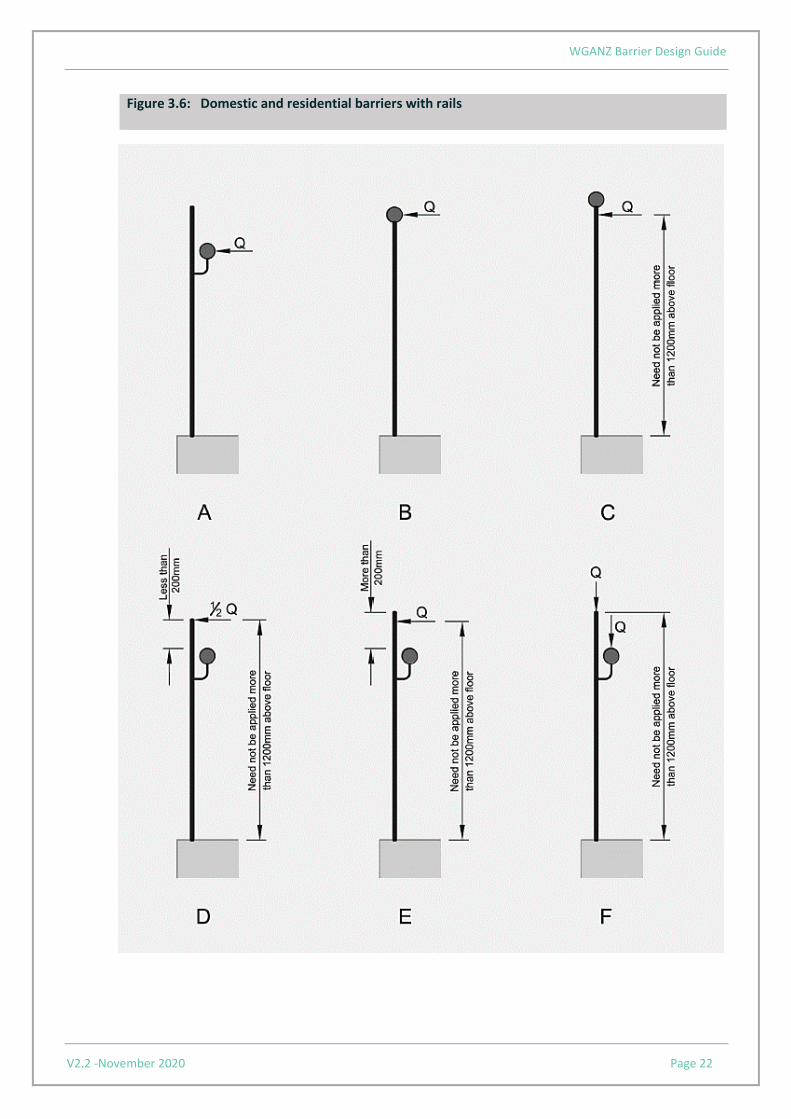
Line loads need not be applied more than 1200mm above the finished floor or stair pitch line. Domestic and residential buildings B1/VM1 paragraph 2.2.7 (a) (i) modifies AS/NZS 1170.1 Clause 3.6 which relates to all domestic and residential barriers including external balconies. Barriers with a rail The diagrams following show how line loads (Q) are to be applied to domestic and residential barriers with rails. Each must be considered as a separate load case.
• Figure 3.6 A and B – When a barrier has a rail or rails, apply the horizontal line load (Q) directly to the top rail.
• Figure 3.6 C – When the barrier or rail is more than 1200mm above the floor or stair pitch line, apply the horizontal line load (Q) at a height no more than 1200mm above the floor or stair pitch line.
• Figure 3.6 D – If the top of the barrier is not a rail, but a rail is within 200 mm of the top of the barrier, apply 50% of the horizontal line load (Q) to the top of the barrier.
• Figure 3.6 E – If there is no rail within 200mm of the top of the barrier, apply the full horizontal line load (Q) to the top of the barrier, but not more than 1200mm above the floor or stair pitch line.
• Figures 3.6 F – Apply the vertical line load (Q) directly to the top of the barrier. Designers may also choose to check any separate top rail that is not the top of the barrier for the vertical line load.
WGANZ Barrier Design Guide
V2.2 -November 2020 Page 22
Figure 3.6: Domestic and residential barriers with rails

WGANZ Barrier Design Guide
V2.2 -November 2020 Page 23
Barriers without a rail The diagrams following show how line loads (Q) are to be applied to domestic and residential barriers without a rail.
• Figure 3.7 A – Apply the full horizontal load at 900mm above the floor or stair pitch line.
• Figure 3.7 B – Separately, apply 50% of the horizontal line load to the top of the barrier. If the height of the barrier is greater than 1200mm, apply the horizontal line load at the height of 1200mm above the floor or stair pitch line.
• Figure 3.7 C – Apply the vertical line load to the top of the barrier.
Figure 3.7: Domestic and residential barriers without a rail

WGANZ Barrier Design Guide
V2.2 -November 2020 Page 24
Buildings other than domestic and residential
Barriers with or without a rail The following diagrams show how line loads (Q) are to be applied to barriers in and around buildings that are not domestic or residential
• Figure 3.8 A – Apply the horizontal line load (Q) to the top edge of the barrier, but not at a height greater than 1200mm above the floor or stair pitch line.
• Figures 3.8 B and C – Where there is a rail, apply the horizontal line load (Q) to the top rail of the barrier.
• Figure 3.8 D – If the top of the barrier is not a rail, but a rail is within 200mm of the top of the barrier, apply 50% of the horizontal line load (Q) to the top of the barrier.
• Figure 3.8 E – If there is a rail but it is not within 200mm of the top of the barrier, apply the full horizontal line load (Q) to the top of the barrier, but not more than 1200mm above the floor or stair pitch line.
• Figure 3.8 F – In all cases, apply the vertical load directly to the top of the barrier and separately to the top rail.

WGANZ Barrier Design Guide
V2.2 -November 2020 Page 25
Figure 3.8: Non-domestic and non-residential barriers

WGANZ Barrier Design Guide
V2.2 -November 2020 Page 26
Infill (distributed) loads
All buildings Figure 3.9 shows how infill loads (P) are applied to barriers.
• Figure 3.9 A and B – Apply the infill load (P) over the whole area of the barrier from the top of the barrier down to the floor.
• Figure 3.9 C – Distribute the applied load to the appropriate load-bearing element. • Distributed loads may be reduced by 50% between 1200mm and 2000mm above
floor level and do not need to be applied above 2000mm from the floor
Note: barriers have to resist other loads, such as wind, which are considered as separate load cases.
Figure 3.9: Infill loads on barriers

WGANZ Barrier Design Guide
V2.2 -November 2020 Page 27
Concentrated loads
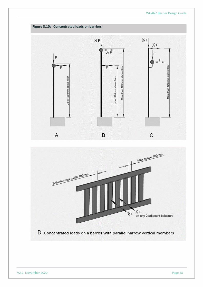
There are two types of concentrated loads in AS/ NZS 1170.1. These are concentrated top edge loads and concentrated infill loads. The top edge concentrated loads are applied inwards, outwards and downwards over a square or circular area of 2000mm2. It should be noted that when a barrier has closely spaced posts the concentrated top edge loads can often exceed the top edge line load requirements. In the case of cantilevered barriers without posts or a rail, i.e. where the infill extends to the top of the barrier and is therefore both the top edge and the infill, both concentrated loads are also applied to the top of the barrier. This can be a critical load case when the concentrated infill loads, for certain occupancy types, exceed the concentrated top edge loads. All buildings Apply the concentrated load (F) at locations to produce the most severe effect on the structural element being considered.
• Figure 3.10 A – When the load position is not more than 1200mm above the floor or stair pitch line, apply the full concentrated load (F).
• Figure 3.10 B – When the load position is more than 1200 mm above the floor, apply 50% of the concentrated load (F) to the barrier top edge or rail.
• Figure 3.10 C – The concentrated load must be applied in the direction and location which produces the most severe effects on the element or connection being considered.
• Figure 3.10 D – If the barrier consists of vertical members less than 100 mm in width and with a gap of less than 100mm between the vertical members, the concentrated load can be split equally between two adjacent vertical members.
WGANZ Barrier Design Guide
V2.2 -November 2020 Page 28
Figure 3.10: Concentrated loads on barriers

WGANZ Barrier Design Guide
V2.2 -November 2020 Page 29
Wind loads
External barriers should be designed to resist the wind loads derived from AS/NZS 1170.2. Wind loads can be the critical loading condition and control the design of the barrier structure when the barrier infill is solid (such as in the case of glass barriers). Particular attention should be paid to high rise buildings and exposed residential buildings where wind loads might be considerably higher. Free-standing screens over 1500mm high, walls, and full height glazing acting as a barrier
Clause B1 Structure of the Building Code requires people to be safeguarded from injury caused by structural failure and requires account to be taken of all loads likely to affect the stability of a building element, including imposed, wind and impact loads. Furthermore, NZBC Clause F4 Safety from Falling requires people to be safeguarded from injury caused by falling and therefore requires a barrier to be provided where people could fall one metre or more to reduce the likelihood of accidental fall and injury. This means that building elements such as tall screens, full height glazing, internal and external walls and windows that protect a difference in level of 1m or more are barriers and therefore must be able to withstand the likely imposed, wind and impact loads without failure. The most appropriate way to comply with these requirements is to design all building elements that act as a barrier in accordance with the B1/VM1 Verification Method (specifically AS/NZS 1170 Parts 1 and 2). However, for walls and full height glazing, the Verification Method B1/VM1 may not always be entirely appropriate and could result in an overly conservative design. In this instance it may be more appropriate to adopt an alternative solution approach as follows.
Addressing the three types of barrier loads in the Standard series AS/NZS 1170 (top edge loads, distributed infill loads and concentrated infill loads) in turn:
• Top edge line loads When the building element does not have a top edge and is greater than 1500mm high, such as in the case of many walls and full height glazed screens, the top edge loads may be omitted. However, where a handrail, rail or transom is present, which could attract a line load in the event of people pressing against the building element, the top edge loads are applied to this element. For free-standing screens which are less than 1500mm high the designer should apply the rules as set out in B1/VM1 with regards to the application of line loads.
• Infill loads Infill distributed loads should always be applied as a minimum and may be exceeded by the wind loads. Distributed loads may be reduced by 50% between 1200mm and 2000mm above floor level and do not need to be applied above 2000mm from the floor.
• Concentrated loads – top edge and infill Generally, top edge concentrated loads should always be applied to any handrail, rail or transom, and concentrated infill loads applied to the infill in a location having the worst effect, but no higher than 1200mm above floor level. If no handrail, rail or transom exists, only the concentrated infill loads are applied to the infill in a location having the worst effect but no higher than 1200mm above floor level.
• Fully framed glazing safeguarding a fall of 1000mm or more Refer NZS4223.3, Table 7, Note 8 re infill concentrated loads for this type of glazing

WGANZ Barrier Design Guide
V2.2 -November 2020 Page 30
3.5 Deflection
General
Beyond the NZBC requirements for barriers to be of adequate strength and stiffness to sustain the applied loads without causing loss of amenity through undue deflection, there are no further mandatory requirements for deflections. Therefore, the key requirement for deflections of barriers is that deflections are limited to prevent people becoming apprehensive or distressed due to excessive movement of the barrier when in normal use. Note: the commentary to AS/NZS 1170.1 includes guidance on deflections of barriers.
Deflections due to wind and infill loads
Wind load deflections occur frequently for external barriers and are often critical for the design of impermeable material barriers such as those of glass or with glass infills. In windy locations and high-rise buildings, the wind load deflection may exceed deflection caused by top edge and concentrated loads. For low-rise buildings, sheltered and internal barriers, deflections caused by barrier infill loads are more critical than deflections due to wind pressures. Deflections due to top edge loads
Top edge and concentrated load deflections occur when people push or are pushed hard (e.g. in a crowd surge) against the top edge, handrail, or corner of a barrier. These loads should not occur on a regular basis and are perhaps less critical in terms of design for amenity. However, in normal use with people leaning or resting against a barrier the deflection of the barrier should not make the occupant feel uncomfortable. Recommended deflection limits
When considering deflection limits it is the total horizontal displacement of the barrier at any point from its original unloaded position which is most critical. The total horizontal displacement is recommended not to exceed 30mm under barrier and wind loads described in B1/VM1. For serviceability, the horizontal deflection of post and rail balustrade systems (measured at the handrail/ top rail) may be considered acceptable if it does not exceed H/60 + L/240 or 30mm, whichever is smaller, where H is the height of the handrail/top rail above the top of the supporting structure (deck or slab) and L is the distance between the centres of the supporting posts to the handrail (see Figure 3.11 below). It is recommended that the deflections of tall barriers are measured at 1200mm above finished floor level to determine the maximum deflection. When calculating deflections of barrier structures, it is important to make allowance for any twisting and rotating of the supporting structure. This is most important when the barrier is fixed to the perimeter of a cantilevered balcony or timber deck as these structures often deflect and distort to a significant extent. A number of proprietary barrier designs assume zero rotation at the support in their associated documentation. In these cases, the designer must:

WGANZ Barrier Design Guide
V2.2 -November 2020 Page 31
a) make an assessment of the validity of this assumption in relation to the particular supporting structure under consideration, and
b) determine whether the actual deflections will be within acceptable limits.
Figure 3.11: Horizontal deflection of post and rail balustrade

WGANZ Barrier Design Guide
V2.2 -November 2020 Page 32
3.6 Supporting structure
Barriers need to be designed and constructed so that they are capable of providing the strength and stiffness necessary for the proposed location and occupancy. Not only does the barrier need to have sufficient strength and stiffness, but the supporting structure to which the barrier is connected must have adequate strength and stability to sustain all applied loads safely without excessive stress, deflection, or distortion.
3.7 Fixings and connections
The fixings securing the barrier system to the supporting structure are of key importance and must have at least equivalent strength to that of the rest of the barrier system. Furthermore, it is recommended all member joints in the barrier be designed to provide the full strength of the members being connected. This is to ensure that under extreme loading the barrier will indicate failure by deflection and distortion rather than by rupture and sudden collapse, as would be brought on by failure of a fixing or connection. When designing fixings, consideration must be given to the substrate into which the fixing is being placed. Substrate (material and strength) and fixing (type, edge distance and spacing) all affect the capacity of the connection. When it is not possible to calculate the capacity of the fixing into a substrate with reasonable accuracy, then load testing should be carried out to validate the design and an appropriate factor of safety applied to the loading. This can often be the case when the substrate is existing and of unknown strength. The integrity of the buildings cladding system must be maintained. Fixing penetrations through claddings must be designed to prevent the penetration of water that could cause undue dampness or damage to building elements.
3.8 Durability
The durability requirements of building elements are covered by New Zealand Building Code Clause B2. For barriers, one way to comply with NZBC Clause B2 is to use Acceptable Solution B2/AS1 which sets out how to determine the durability requirements for building elements. Figure 3.12 sets out the specific durability requirements for barriers. Clearly, the supporting structure has a 50-year durability requirement as it is part of the building’s structure. The posts and handrails normally also have a 50-year durability requirement. This is based on the assumption that the building element (post/rail) is either difficult to access and replace, or that failure would go undetected in both normal use and maintenance. However, if it can be shown that the post, handrail and fixings can be accessed and replaced without difficulty and that failure would not go undetected, then it would be acceptable to reduce the durability requirements for these elements to 15 years. Likewise, if the barrier infill was difficult to access and replace or failure of the infill would go unnoticed, e.g. the support of the infill is hidden, then the durability requirements of the barrier infill would need to be increased. It should be noted that failure in this instance means no longer complying with other clauses of the New Zealand Building Code.

WGANZ Barrier Design Guide
V2.2 -November 2020 Page 33
Figure 3.12: Assessment of durability for barriers
An option within the Acceptable Solution is to use Table 1 of B2/AS1. This table sets out specifically the durability requirements for most building elements. Figure 3.13 below details these requirements for barriers.

WGANZ Barrier Design Guide
V2.2 -November 2020 Page 34
Figure 3.13: Barrier and supporting structure durability requirements
For information on material compatibility in relation to durability refer to Acceptable Solution E2/AS1 Tables 20 to 22.

WGANZ Barrier Design Guide
V2.2 -November 2020 Page 35
Figure 3.14 describes the durability requirements for the components of a glazed barrier system.
Figure 3.14: Assessment of durability for glazed barrier systems Building Element
Component Situation/Function Not less than
50 years
Not less than
15 years
Not less than
5 years
Glazed safety barrier
Attached support posts, for both infill type and structural balustrades
Y
Embedded support posts, for both infill type and structural balustrades
Y
Exposed cantilevered channels or clamps
Y
Hidden or embedded cantilevered channels or clamps
Y
Fixings to building/structure
Screws, bolts, anchors, or similar attaching balustrade system to building or structure
Y
Glass fixings Bolts, or similar attaching glass to balustrade system
Y
Balusters, and glass panels
Y
Gaskets, sealant, and glazing beads
Moderately difficult to access or replace
Y

WGANZ Barrier Design Guide
V2.2 -November 2020 Page 36
3.9 Safety details
The barrier including the infill should have no sharp edges or projections that may cause injury when restraining people. Consideration also needs to be given to the possibility of tampering and vandalism when designing for safety.
3.10 Testing procedures/protocols
Test Loads Barriers are required to resist a range of minimum “design loads”. These loads are specified in Table 3.3 AS/NZS 1170.1 for the various occupancy types. (Reproduced in part as Table 3.3 in this document). The loads are either applied as line loads, point loads or uniform (pressure) loads. These are unfactored imposed (live) loads. A designer conducting an analytical design of a barrier system is required to factor the loads according to AS/NZS 1170.0 to allow for uncertainty in the actual value of the loads in practice, as would be done with the design of other structural elements. With calculations for barriers, the factor to be used by the designer for strength is 1.5 and for service (deflections) 1.0. When tests are undertaken to establish the strength and stiffness of barrier systems, there is no particular standard that specifies how this is to be done. However, the tests that will be undertaken are effectively prototype tests and guidance is provided in Appendix B of AS/NZS 1170.0 on the load multiplier that should be used when conducting such tests on barrier systems. This multiplier is determined on the basis of the variation in the structural characteristics of the system. The variation may not be known, and if a single test is to be conducted on the system for a particular load condition there is no opportunity to ascertain the variation. However, the materials being used in the construction of the barrier are likely to be reasonably well known (timber has the greatest variability of the majority of materials that will form a part of a barrier) and an estimate of the likely variability can be made. Once this is made, the test target load level can be established by multiplying the factored design load by the load multiplier. By conducting several replicate tests, a greater confidence can be established in the likely performance of the system in service and the test target loads can be reduced (in accordance with Table B1 of AS/NZS 1170.0). It is important to correctly model the critical service conditions in the tests. For example, the base fixing of the barrier to the substrate must be correctly modelled: fixing a baseplate which is expected to be installed on a timber substrate to a heavy steel substrate in the laboratory will not adequately model the expected service deflections. Similarly, components within the system must be faithfully modelled. The sequence of load application on a test specimen is important to ensure the greatest benefit can be obtained from the tests. The best sequence can be estimated by pre-test calculation of likely failure loads of the components of the system to determine the weakest element and under which load failure is most likely to occur.

WGANZ Barrier Design Guide
V2.2 -November 2020 Page 37
Load durations
The specimen shall be loaded at a constant rate with deflections preferably recorded continuously. The duration of the test should not be less than five minutes.
Test specimen conditioning
The performance of some materials in the field is likely to be governed by the weather, particularly rain. For example, timber elements are likely to undergo moisture content changes with the seasons, particularly if they are not paint protected. A system under test should have a moisture condition as near as possible to that which it would experience in service. If the system is unprotected and exposed to rain, then the moisture condition of the test specimens should be high enough to accurately simulate the field behaviour. Normal fluctuations in air temperature are not likely to affect the performance of any barrier system.
Application of the test loads to the specimen
The test loading must accurately simulate the loads specified in the loadings Standard. The line load, for example, must be applied without the possibility of the application rig strengthening the barrier system – and the uniform pressure load should generally be just that. This is especially important for elements of the infill system that “span” in two directions, such as panel products that are supported along all four edges. It will be appropriate to use a series of line loads to simulate the pressure loads on some occasions, but the appropriateness must be agreed with the testing authority prior to conducting the testing.
Testing safety
When a test load is being applied to a specimen a significant amount of potential energy can accumulate as the system displaces under load. Testing laboratories should always estimate the likely physical behaviour of the specimen should it fail under load and ensure those witnessing the test are kept at a safe distance from the specimen.
Testing of structural glass barriers with stiff interlayer and dual pane fracture
The testing of a heat-strengthened or toughened laminated safety glass barrier with a stiff interlayer that does not have an interlinking rail shall be carried out in accordance with Section 7 of Acceptable Solution B1/AS1 to demonstrate compliance with the load and deflection requirements. Physical testing must include all components of the barrier system, including structural connections. Loads and deflections must be applied and measured horizontally, at midspan, at the required barrier height. The concentrated load shall be applied over an area of 100 mm x 100 mm and for at least one minute. Test results for dual pane fracture are not applicable to barriers that have narrower glass panes than that tested. When both pane of the laminate are fractured, the barrier shall resist a 0.2 kN concentrated load and not deflect more than 250 mm.

WGANZ Barrier Design Guide
V2.2 -November 2020 Page 38
4.0 Barrier materials
4.1 Glass
4.1.1 Glass type
Glass used in barriers shall be toughened or laminated safety glass complying with NZS4223.3:2016. Note: Laminated safety glass can be annealed, heat strengthened or toughened laminated glass, depending on application.
4.1.2 Glass marking
All safety glass must be permanently marked in accordance with the requirements of Clause 2.8.2 of NZS4223.3:2016 to comply with Acceptable Solution F2/AS1. Markings must remain visible after installation.
4.1.3 Glass design
Glass design shall be in accordance with NZS 4223 Parts 1, 2, 3 and 4 and Acceptable Solution B1/AS1 or specific engineering design to B1/VM1.
4.1.3.1 Insulating glass units (IGUs)
The inner glass shall be designed to meet the relevant barrier loads as defined in this guide, the human impact safety requirements and the load shared from wind loads. The outer glass shall be designed to meet the load shared from wind loads and the human impact requirements, if applicable (refer NZS4223.3:2016, Clause 2.7). Note: Where the glazing is safeguarding a fall of 1000 mm or more, human impact is unlikely to occur on the outer panes. In such cases it is normal to check the unit combination for wind loading and then check the inner panes complies with section 21 of NZS 4223.3:2016.
4.1.3.2 Holes in glass
Special attention should be given to the stresses around fixing holes as these are often much higher than stresses away from the holes. These stresses may be determined using finite element analysis (FEA) or measured using strain gauges. Figure 4.1 shows a FEA stress diagram of a glass pane supported by disc fittings under a uniformly distributed load along the top edge.

WGANZ Barrier Design Guide
V2.2 -November 2020 Page 39
Figure 4.1: Barrier and supporting structure durability requirements
Note: Image indicates a single glass panel with six fixings holes across the bottom edge. Red colour shows areas of highest stress.
4.1.4 Glass barrier types (balustrades) 4.1.4.1 Screens and full-height glass barriers
Glass screens over 1500mm high and full-height glass acting as a barrier safeguarding against a fall of one metre or more shall meet the design criteria set out in Section 3.4. Fully framed glazing screens and full-height glass barriers, (such as building facades) shall comply with Figure 4.2, replicating NZS4223.3:2016, Table 7. Partly framed, full-height glazing safeguarding against a fall of one metre or more should comply with Table 4.1, replicating NZS4223.3:2016, Table 8.

WGANZ Barrier Design Guide
V2.2 -November 2020 Page 40
Figure 4.2: Fully framed Glazing safeguarding a fall of 1000mm or more

WGANZ Barrier Design Guide
V2.2 -November 2020 Page 41
Table 4.1: Full-height, partly framed glazing safeguarding a fall of 1000mm or more

WGANZ Barrier Design Guide
V2.2 -November 2020 Page 42
4.1.4.1 Glass infill barriers
Glass infill barriers are normally classified by the support provided to the glass edges, including but not limited to the following.
• Balustrade Infill – four edge support
• Balustrade Infill – two edge support
• Balustrade Infill – two edge support – point fixed
• Balustrade Infill – two edge support – point fixed with handrail in front
• Balustrade Infill – two edge support – clamp fixed
Infill panels shall meet the design criteria for infill concentrated loads and uniform pressure loads. Note: Wind pressure on glazing must also be considered as this may be the worst load for design. For glass design, refer to Tables 4.2 to 4.6 replicating NZS4223.3:2016, Tables 9 - 13.

WGANZ Barrier Design Guide
V2.2 -November 2020 Page 43
Table 4.2: Infill balustrade – four-edge support

WGANZ Barrier Design Guide
V2.2 -November 2020 Page 44
Table 4.3: Infill balustrade – two-edge support

WGANZ Barrier Design Guide
V2.2 -November 2020 Page 45
Table 4.4: Infill balustrade – two-edge – point fixed

WGANZ Barrier Design Guide
V2.2 -November 2020 Page 46
Table 4.5: Infill balustrade – two-edge support – point fixed with handrail in front

WGANZ Barrier Design Guide
V2.2 -November 2020 Page 47
Table 4.6: Infill balustrade – two-edge support – clamp fixed (no holes in glass)
WGANZ Barrier Design Guide
V2.2 -November 2020 Page 48
4.1.4.3 Structural glass barriers
Structural glass barriers use glass as a structural element and are normally classified by the following types:
• Structural Balustrade – cantilevered glass
• Structural Balustrade – two edge point fixed
• Structural Balustrade – two edge support
• Structural Balustrade – three edge support
All structural glass barriers safeguarding a fall of 1000mm or more shall have interlinking rails (see 1.2 Definitions). Interlinking rails are not required for a heat strengthened or toughened laminated safety glass barrier that:
a) has a top capping, corner brackets or a proprietary system to hold the glass in place in case of dual pane fracture (see Note 2), and will, when both panes of the laminate are fractured, resist a 0.2 kN concentrated load and not deflect more than 250 mm, or
b) has two or three edge supported by a structural sealant joint or continuous clamp, and will, when both panes of the laminate are fractured, resist a 0.2 kN concentrated load and not deflect more than 250 mm (see Note 2), or
c) has a stiff interlayer that when both panes of the laminate are fractured, resist a 0.2 kN concentrated load and deflect more than 250 mm. Physical testing must be undertaken to demonstrate compliance with the load and deflection requirements. (Note 3)
Physical testing of glass barriers must include all components of the barrier system, including all structural glass connections. Loads and deflections must be applied and measured horizontally, at midspan, at the required barrier height. The concentrated load must be applied over an area of 100 mm x 100 mm and for at least one minute. Note:
1. The design of structural connections, fasteners and mounting hardware, that are part of the glass barrier, is outside the scope of this guide and NZS 4223.3:2016.
2. Laminated glass is susceptible to minor edge delamination, depending on the interlayer and laminating process. Normally this will not affect the mechanical properties but may be noticeable on exposed edges.
3. Test results for dual pane fracture of laminated glass barriers with stiff interlayers are not applicable to barriers that have narrower glass panes than that tested.
Application of line loads
The application of design line loads for a cantilevered monolithic toughened structural glass barrier with an interlinking rail shall be as follows. In accordance with Section 7.0 of Acceptable Solution B1/AS1, interlinking rails must be fitted at the minimum barrier heights from Table 1 of Acceptable Solution F4/AS1.

WGANZ Barrier Design Guide
V2.2 -November 2020 Page 49
In the event a glass pane breaks, the interlinking rail is designed to span across the broken pane at the required barrier height, and resists SLS design line and concentrated loads without deflecting more than 100 mm in any direction. There are no size restrictions on interlinking rails except for requirements to meet strength and deflection under SLS design line and concentrated loads. Interlinking rails that are wider than 30 mm in plan may be designed as load bearing interlinking rails to resist ULS design loads as provided by clause 2.2.7 of Verification Method B1/VM1. Interlinking rails that serve as handrails for stairs and ramps as required by clause D1 Access Routes, shall be designed for adequate strength under ULS design loads and rigidity under SLS design loads, as required by Clause B1 Structure, regardless of the widths in plan of the interlinking handrails. Design line loads need not be applied more than 1200mm above the floor or stair pitch line.
Domestic and residential buildings For barriers with interlinking rails that are 30mm wide or less in plan, design line loads are applied at 900mm above the floor or stair pitch line irrespective of the height of the barriers. For barriers with load bearing interlinking rail that are wider than 30mm in plan, and less than 200mm from the top edge of the glass, apply the line load to the load bearing interlinking rail, and 50 % of the line load to the top edge of the glass as a separate load case. For barriers with load bearing interlinking rails that are wider than 30mm in plan, and more than 200mm from the top edge of the glass, apply the line load to top edge of the barriers, but not higher than 1200mm above the floor.
Other buildings For barriers with interlinking rails that are 30mm wide or less in plan, apply the design line loads at the top edge, but not higher than 1200mm above the floor or stair pitch line. For barriers with load bearing interlinking rail that are wider than 30 mm in plan, and less than 200mm from the top edge of the glass, apply the line load to the load bearing interlinking rail, and 50 % of the line load to the top edge of the glass as a separate load case. For barriers with load bearing interlinking rails that are wider than 30 mm in plan, and more than 200mm from the top edge of the glass, apply the line load to top edge of the barriers, but not higher than 1200mm above the floor or stair pitch line.
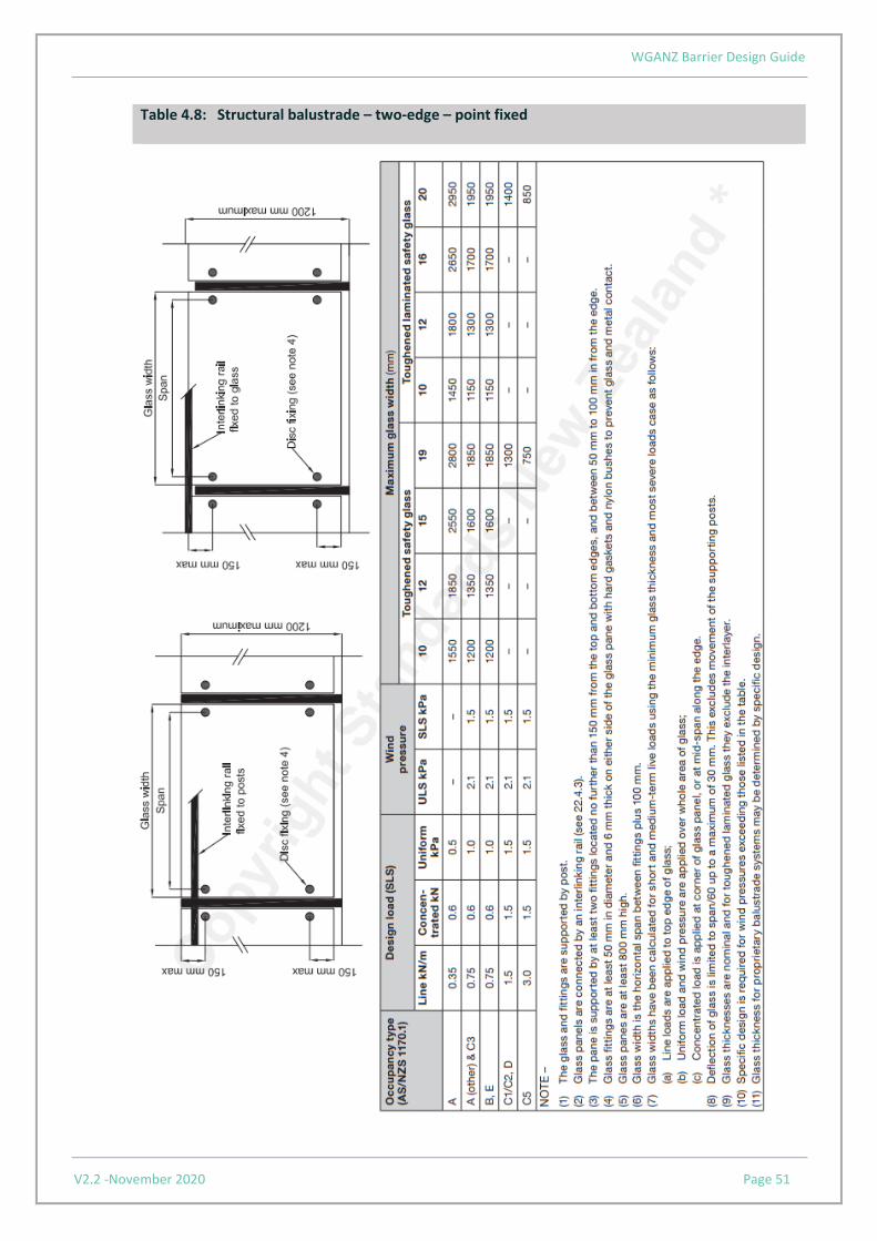
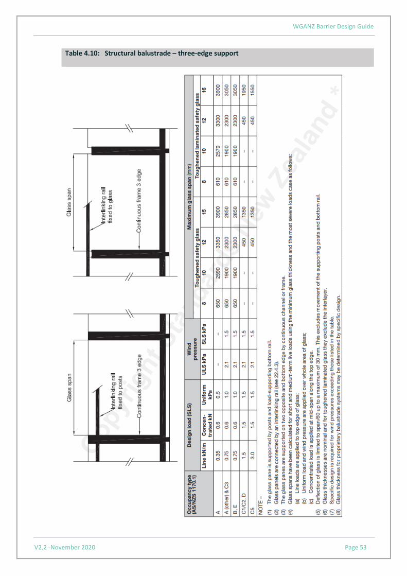
For glass selection refer to Tables 4.7 to 4.10, replicating NZS4223.3:2016, Tables 14 – 17, as set out below; Note: 1) Please also refer to B1/AS1, 7.3.1 for modifications to NZS4223.3. 2) Wind pressure on glazing must also be considered as this may be the worst load for design.

WGANZ Barrier Design Guide
V2.2 -November 2020 Page 50
Table 4.7: Structural balustrade infill – cantilevered glass
WGANZ Barrier Design Guide
V2.2 -November 2020 Page 51
Table 4.8: Structural balustrade – two-edge – point fixed

WGANZ Barrier Design Guide
V2.2 -November 2020 Page 52
Table 4.9: Structural balustrade – two-edge support
WGANZ Barrier Design Guide
V2.2 -November 2020 Page 53
Table 4.10: Structural balustrade – three-edge support

WGANZ Barrier Design Guide
V2.2 -November 2020 Page 54
4.1.4.4 Glass fences
Glass fences, including swimming pool fences, that safeguard against a fall of one metre or more are also barriers and shall comply with the barrier design criteria in Section 3 and this section. Note. Wind pressure on glazing must also be considered as this may be the worst load for design.
4.1.4.5 Glass combination barriers
Barriers using a combination of infill and structural elements are subject to specific design using the barrier design criteria in Section 3 of this guide and NZS4223.1:2008.
4.1.5 Rails and handrails
Rails, interlinking rails, and handrails are defined in Section 1. For handrail requirements in relation to accessible routes, refer to paragraph 6.0 of Acceptable Solution D1/AS1. When handrails are fixed directly to glass through holes in the glass, they can cause high localized stresses in the glass and the designer shall ensure the fixing type and hole centres are adequate to support the design criteria. (See Section 4.1.3.2)
4.1.6 Working on glass
All shape cutting, edgework, hole drilling and notches shall be undertaken prior to installation and prior to toughening, if toughened glass is required. Notches and holes shall not be used in annealed laminated glass. (See Section 4.1.3.2)
4.1.7 Installation
Contact between glass and any other hard material (including other glass parts) shall be avoided. Wedges, backing seals, glazing tapes, gaskets, or sealants shall be used to prevent glass to metal contact. Generally, the installation should follow the manufacturers specification, or
a) The supporting frame sections should have a minimum edge cover of 12mm for two- and three-edge support and four-edge support should comply with NZS 4223.1 Table 5.
b) When bolted or point fixings are used, the holes shall have inserts of incompressible bushes normally 2 - 5mm thickness.
c) For clamping plates or discs, hard fibre or plastic gaskets (0.5mm minimum thickness) shall be used. Clamp fixings shall be a minimum of 50mm square or circular and 6mm thick, unless testing or specific design can show that the stresses around the holes are not excessive.
d) The frame and/or fixings shall be designed not to distort the glass panel and put undue stress in the glass.

WGANZ Barrier Design Guide
V2.2 -November 2020 Page 55
4.1.8 Maintenance
All glass panels should be regularly cleaned, and fixing should be checked for loosening, gasket deterioration and corrosion. Regular washing and drying of glass affect long-term durability, especially during construction. The most important operation is to dry the glass after washing using a clean grit-free squeegee, cloth, or paper towel. Grease marks or glazing compounds and sealant should be removed before washing, which is best done out of direct sunlight using proprietary cleaners or soapy water.
Suggested maintenance schedule:
• Constructions sites – check weekly for build-up and clean every one to two months • Industrial sites – Clean every one to two months • Urban areas – Clean every three months • Rural areas – Clean every six months unless crop spraying or sprinkling with bore water

WGANZ Barrier Design Guide
V2.2 -November 2020 Page 56
4.2 Timber
4.2.1 Materials
Timber used for barriers should comply with the species and grades described in NZS3603:1993 Timber Structures Standard.
4.2.2 Design General
The design of all timber barriers should be in accordance with NZS3603:1993 Timber Structures Standard. Using the design criteria given in Section 3 of this guide, the stresses used in the design must be appropriate for the grade of timber selected. The minimum imposed actions from Table 3.2 should be considered to be of brief duration as defined in Table 2.4 of NZS3603:1993. For external barriers that are not enclosed or clad to prevent the ingress of moisture, the characteristic timber stresses used in the design of the barrier should be those for green timber, i.e. where the in- service moisture contents are likely to be 25% or over.
Joints
All joints in the timber should be designed in accordance with NZS 3603:1993. Where proprietary fixings are proposed it is important to ensure the joints are designed in accordance with the manufacturer’s instructions and technical guidance, taking into account such things as: timber strength, fixing embedment, fixing centres, fixing durability, edge distances and whether the capacities quoted are working stress loads or ultimate strength values.
4.2.3 Fabrication Moisture content
The moisture content of the timber should, as far as reasonably practical, be appropriate to the position in which it is to be used.
Preparation of timber
The surface finish to all barriers should be smooth and clear of any projections that would cause injury. All sharp edges should be removed to reduce splintering. Handrails should be smooth finished and of a type of timber not liable to produce splinters in use.
Assembly
The components of barriers should be connected to each other using the methods recommended in NZS 3603:1993. Trial assemblies of prefabricated barriers are recommended.

WGANZ Barrier Design Guide
V2.2 -November 2020 Page 57
4.2.4 Durability/treatment
All timber used in barriers must meet the durability requirements of Clause B2 of the NZBC. This can be achieved by complying with NZS 3602:2003: Timber and Wood-based Products for Use in Building with the modifications set out in Acceptable Solution B2/AS1. All metal fixings must also be designed to meet the durability requirements of Clause B2. Care is required to ensure there are no incompatibilities between the metal fixings (including coating systems) and the preservatives used in the treatment of the timber members. For external timber barriers where fixings are used in contact with timber treated with Copper Azole or Alkaline Copper Quaternary (ACQ) preservatives, the fixings shall be Type 304 stainless steel. For further details, refer to clause 4.4.4 of NZS 3604: 2011 Timber-framed buildings.
4.2.5 Installation
Care should be taken to avoid overstressing of members during fixing. All site bolted joints should be inspected, and all bolts should be carefully tightened without crushing the wood under washers. All metal fixings should be protected from corrosion.
4.2.6 Maintenance
The periodic cleaning and the renewal of certain finishes is necessary to maintain the durability of the barrier system. All joints and connections should be checked for movement within the joints. Screws, nails, and bolts should be checked for corrosion.
4.2.7 Timber barrier design for residential and domestic buildings
4.2.7.1 Scope
This design applies to the construction of timber barriers for residential and domestic buildings. The design will have an expected life in accordance with Acceptable Solution B2/AS1 Table 1, i.e. 50 years for the supporting structure, structural posts and handrail, and 15 years for the infill (palings and rails). This design solution will satisfy the requirements of NZBC Clause F4 for the protection of children under the age of six years. All timber used should be grade SG8 (wet) (MSG8 and VSG8), except for the palings which can be SG6 (No. 1 Framing). Cross-sectional dimensions noted are the actual finished sizes of the timber.
Barriers should have:
• all timber preservative treatment complying with NZS 3602: 2003.
• metal fixings and fasteners complying with section 4.4 of NZS 3604: 2011.

WGANZ Barrier Design Guide
V2.2 -November 2020 Page 58
4.2.7.2 Construction General
A barrier may comprise structural posts, handrail, top and bottom rails and palings. The supporting structure should be in accordance with section 7.4 of NZS 3604:2011.
Handrail
The 90mm x 45mm handrail should be fixed with four 100mm x 3.75mm nails to the top of each structural post as shown in Figure 4.11. At the locations of handrail joins there should be two nails in each handrail connected to the structural post.
Structural Posts
The 90mm x 90mm structural posts should be fixed to either a double end joist or to a double boundary joist. The two situations are shown in Figure 7.10(c) of NZS 3604:2011. Where a structural post is fixed to an end joist or a boundary joist, it should be fixed with two M12 bolts as shown in Figure 4.11. The structural post should be positioned in accordance with Figure 7.10(c) of NZS3604:2011.
Figure 4.11: Handrail fitting to glass

WGANZ Barrier Design Guide
V2.2 -November 2020 Page 59
Top and Bottom Rails
The top and bottom rails span between the structural posts and should be 90mm x 45mm. Where the rails are cut between the structural posts the rails should be fixed at each end with four skewed 100mm x 3.75mm nails. It is also acceptable to fix the rails to either the inner or outer faces of the structural posts. In these instances, the rails should be fixed to either the inner or outer faces of each structural post with four 100mm x 3.75mm nails.
Palings
Palings should be 125mm x 25mm timbers spanning between the top and bottom rails. Palings are to be installed with a maximum gap between palings of 100mm. Palings are to be connected to both the top and bottom rails. Each connection of the paling to the top and bottom rail should have three 60mm x 3.15mm nails. Palings may be fixed to either side of the rails. Note: Other infills may be used in conjunction with the structural posts and handrails detailed here, but the infill and its connections will require specific design.

WGANZ Barrier Design Guide
V2.2 -November 2020 Page 60
4.3 Metals
4.3.1 General
This section provides guidance on the most common metals used in barriers and relates to the fabrication, corrosion protection and installation of metal barriers. Where the barrier contains a glass panel infill, refer to section 4.1. This guidance may be suitable for other metals not covered in this guide, subject to the provision of additional research and investigation.
4.3.2 Aluminium
Aluminium barriers should be designed in accordance with AS/NZS 1664.1:1997 or tested to comply with AS/NZS 1170.0:2002 Appendix B.
Corrosion resistance
Aluminium has good corrosion resistance. This is due to the oxide film that bonds strongly to its surface and, if damaged, re-forms quickly in most environments. Aluminium’s durability can be improved further by anodising.
Anodising
The anodising process involves passing a controlled electrical current through extruded aluminium profiles immersed in an acidic (sulphuric) solution, which forms a protective film of aluminium oxide on the surface of the aluminium. The protection of the aluminium section improves as the thickness of the anodising increases. Typical thicknesses of anodising for different environmental conditions are shown below:
• 12 microns – sheltered, non-coastal areas including internal environments • 20 microns – exposed and inland areas (minimum recommended for
balustrades/barriers) • 25 microns – coastal and geothermal areas
SFA 3503-03:2005 Window & Glass Association NZ Voluntary Specification for Anodic Coatings details the anodising process.
Surface finishes
The following Standards cover surface coatings to aluminium as per the American Architectural Manufacturers Association (AAMA):

WGANZ Barrier Design Guide
V2.2 -November 2020 Page 61
• AAMA 2603-05 – Voluntary Specification, Performance Requirements and Test Procedures for Pigmented Organic Coatings on Aluminium Extrusions and Panels
• AAMA 2604-05 – Voluntary Specification, Performance Requirements and Test Procedures for High Performance Organic Coatings on Aluminium Extrusions and Panels
• AAMA 2605-05 – Voluntary Specification, Performance Requirements and Test Procedures for Superior Performing Organic Coatings on Aluminium Extrusions and Panels
Stove paints or powdercoatings can be extremely durable. When these are to be used, specialist advice should be sought from the coating manufacturer regarding specification and suitability (particularly, durability zones) and application of the coatings.
Maintenance
The cleaning of powdercoated and anodised material should be performed using hand cleaning and rinsing techniques. The powder coated surface must be regularly maintained in accordance with the powder coating manufacturer's data sheets and in areas where there is a high concentration of salt or atmosphere pollutants, a systematic maintenance program meeting AAMA 610.1 1979 should be implemented. At the very minimum, cleaning should be done at three- to six-month intervals (depending on location, e.g. seaside or inland, rural or industrial etc.) and is often part of the regular cleaning program associated with items such as the glazing or balustrades of the property.
The following procedure should be adopted: • remove dust with a wet sponge rather than risk micro-scratching the surface by
dry dusting • most marks or surface contaminants can be removed by the use of a warm, mild
detergent or mineral turpentine / white spirit • always rinse gently afterwards with fresh water so that the contact time of the
cleaning solution is kept to a minimum • high-pressure hosing must be avoided under all circumstances • dry, preferably with a chamois, or alternatively, a soft cloth • do not use an abrasive type cleaning agent as this will severely damage the
surface of the material • cleaning of the product should be performed at a time that will allow the
aluminium to dry quickly, preferably early in the morning.
Note: All coated aluminium surfaces should avoid contact with acids, alkalis, mortar-based products and solvents.
4.3.3 Steel
Steel barriers should be designed in accordance with NZS3404.1:1997 and related amendments or tested to comply with AS/NZS 1170.0:2002 Appendix B.
WGANZ Barrier Design Guide
V2.2 -November 2020 Page 62
4.3.3.1 Mild steel
Corrosion resistance
Bare mild steel has relatively poor corrosion resistance. Use of mild steel without a corrosion-resistant coating is only appropriate in internal non- corrosive environments. Usually it is selected not for its corrosion resistance but for such properties as strength and ease of fabrication. Corrosion protection of steel is covered by Appendix C of NZS3404.1:1997 which is cited in Verification Method B1/VM1. However, the latest corrosion protection information is contained in section 2 of SNZ TS3404:2018 Steel Structures Standard and should be used in preference.
Galvanising The following Standards deal with galvanising of steel elements:
• AS/NZS4680:2006 Hot-dip galvanised (zinc) coating details the requirements for galvanising
• AS/NZS4792:2006 Hot-dip galvanised (zinc) coatings on ferrous hollow sections, applied by a continuous or a specialized process.
After fabrication all surface contaminants should be removed. The galvanised coating must be continuous, adherent, smooth and evenly distributed. The element should also be free from any defect that would be detrimental to the use of the element in a barrier. This is particularly relevant to handrails.
4.3.3.2 Stainless steel
Corrosion resistance
Stainless steel does not corrode as easily as mild steel but, unlike its name suggests, it can stain and become dull relatively quickly. Stainless steel is used where the properties of mild steel are required and resistance to corrosion is important. Grade 304 stainless steel should be used only in non- corrosive environments. In corrosive environments such as coastal, swimming pools and geothermal areas, grades 316, 2205 or 445M2 stainless steel should be used.
Surface finishes
The most suitable and common surface finishes used for stainless steel in New Zealand are based on ASTM standard A480/A480M-11a:
• Mill Finish (2B) – Satin • Brushed (no.4) – Directional Grain • Bright (BA) – Mirror Finish (polished)

WGANZ Barrier Design Guide
V2.2 -November 2020 Page 63
Maintenance
The use of a stainless steel cleaner is recommended to protect the stainless steel. The cleaner should be used once every three months. Stainless steel balustrades exposed to the external environment may require more frequent cleaning if any deterioration of the balustrade is detected. At a minimum, all exposed stainless steel surfaces should be wiped over with a clean cloth and warm water with a mild detergent on a frequent and routine basis. For more stubborn dirt or stains use mild, non-scratching abrasion powders such as typical household cleaners. These can be used with warm water, bristle brushes, sponges or clean cloths. For more aggressive cleaning a small amount of vinegar can be added to the powder. Carbon steel brushes and steel wool must be avoided as they may leave particles embedded in the surface, which can lead to rusting. The maximum recommended frequency for routine cleaning is once a month, but more often in areas subject to heavy soiling or frequent use.
DOs
• Routine simple and gentle cleaning • Use cleaners showing “Suitable for stainless steel” • Employ repeated, routine cleaning rather than an aggressive single cleaning
DON’Ts
• Use coarse abrasive powders • Use metallic scourers • Use “Silver cleaners” • Use in an “abnormal” way
4.3.4 Fabrication
Aluminium is an easy product to fabricate and can be readily manipulated in a cold state. Most aluminium extrusions can be curved, provided the design, alloy and temper are appropriate. Aluminium extrusions can be mechanically fixed or welded. The most common practice with aluminium is to fix mechanically using stainless steel fixings.
4.3.5 Fixings and connections
Proprietary fixings should be used in accordance with the manufacturer’s instructions. Particular attention needs to be given to minimum edge distances and fixing centres when fixing to substrates, especially timber and concrete. All fixings and connections including assembly, infill and substrate connections which make up the barrier system must meet the durability requirements of NZBC Clause B2. For guidance on durability in relation to barriers, refer to section 3.8 of this guidance document.

WGANZ Barrier Design Guide
V2.2 -November 2020 Page 64
4.3.6 Installation
Installations must be in accordance with the manufacturer’s and engineer’s specifications. Consideration needs to be given to the durability and compatibility of materials in contact (barrier material, fixings and fixing substrate) prior to installation.

WGANZ Barrier Design Guide
V2.2 -November 2020 Page 65
5.0 Checklist The following checklist is intended to assist the designer, installer and BCA to determine that the design and documentation is sufficiently adequate and complete.
Things to consider ✓
Initial considerations?
Is the proposal a barrier?
Is the proposal a Specific Engineered Design?
Is an engineer required?
Is the deck designed to NZS 3604:2011 - 7.4?
What type of barrier is proposed: glass, timber, metal, wire infill, concrete or a combination?
Is a handrail required?
Design of barriers
B1
Has the appropriate occupancy type (Table 3.3 of AS/NZS 1170.1) been used?
Has the barrier been designed in accordance with the loads specified in AS/NZS 1170?
Does the design take account of barrier top edge line loads, infill loads and concentrated loads?
Have wind loads been considered, i.e. is the barrier outside, in a high-wind zone or on a high-rise building?
Has consideration been given to barrier deflections, and is rotation of the supporting structure likely?
Are the fixings to the supporting structure sufficiently designed and detailed?
If the barrier design is based on testing, was the testing sufficiently robust and thorough (see Appendix B of AS/NZS 1170.0)?
B2
Is the durability of the barrier appropriate for its purpose, location, and accessibility (see Acceptable Solution B2/AS1)?
E2
For barriers fixed through cladding systems, does the design provide adequate resistance to penetration by, and the accumulation of, moisture from the outside (see section 7.4 of Acceptable Solution E2/AS1)
F4
Does the barrier geometry and height conform to NZBC Clause F4 Acceptable Solution 1, e.g. toeholds?

WGANZ Barrier Design Guide
V2.2 -November 2020 Page 66
Things to consider (cont.) ✓
Materials
Glass
Have the design criteria in this design guide been used?
If not, has compliance been established?
Timber
Have the members and joints been designed in accordance with NZS 3603 Timber Structures Standard?
Have green timber stresses been used in the design where the barrier is external and exposed to the weather?
Is the timber treatment appropriate for the durability requirements of the barrier?
Metal
Have the design criteria in this design guide been used?
Has compliance been established by other means?
Concrete
Has the barrier been designed in accordance with NZS 3101 Concrete Structures Standard?
Are the materials and construction in accordance with NZS 3104 and NZS 3109?
If proprietary drilled-in fixings are proposed, have they been sufficiently designed and detailed for the application?
Maintenance
What are the manufacturer’s requirements for maintenance?
Have the property owners been notified of the maintenance requirements?
Producer statements
Is the producer statement (PS1) site and job specific?
Is the PS3 for the same system as approved on the Building Consent?
Has other evidence has been provided to show compliance?