barrier systems, inc. page 38 of 40 - innovative...
TRANSCRIPT


Barrier Systems, Inc. RTS-QMB Longitudinal Barrier
STI Project: QBOR1
Page 38 of 40
Figure F-3
Appendix F (Continued)

B
arrie
r Sys
tem
s, In
c.
RTS
-QM
B L
ongi
tudi
nal B
arrie
r
STI P
roje
ct:
Q
BO
R1
P
age
12 o
f 40
Fi
gure
1.
Sum
mar
y of
Res
ults
-Tes
t #Q
BO
R1
t=0.
000
sec
t=.1
00se
ct=
.200
sec
t=.4
00se
ct=
.500
sec
t= 1
.0se
c
Gen
eral
Info
rmat
ion
Exit
Cond
ition
s
Te
st A
genc
y……
……
……
……
……
……
……
……
SAFE
TEC
HNO
LOG
IES,
INC.
Spee
d (k
m/h
)……
……
……
……
……
……
……
……n
/a
Te
st D
esig
natio
n……
……
……
……
……
……
……
NCHR
P Re
port
350
Test
3-1
1
An
gle
(deg
)……
……
……
……
……
……
……
……
…n/a
Test
No…
……
……
……
……
……
……
……
……
…Q
BOR1
Occ
upan
t ris
k Va
lues
Date
……
……
……
……
……
……
……
……
……
….
4/9/
2004
Im
pact
Vel
ocity
(m/s
)Te
st A
rticl
e
x
-dire
ctio
n……
……
……
……
……
……
……
…8.
4
Ty
pe…
……
……
……
……
……
……
……
……
……
.Bar
rier S
yste
ms,
Inc.
y-d
irect
ion…
……
……
……
……
……
……
……
-7.7
18" C
RTS/
QM
B Lo
ngitu
dina
l Bar
rier
Rid
edow
n Ac
cele
ratio
n (g
's)In
stal
latio
n Le
ngth
……
……
……
……
……
……
…11
5 m
eter
s ov
eral
l
x
-dire
ctio
n……
……
……
……
……
……
……
…-1
0.9
Size
and
/or d
imen
sion
and
mat
eria
l
y
-dire
ctio
n……
……
……
……
……
……
……
…17
.2
o
f key
ele
men
ts…
……
……
……
……
……
……
….C
RTS
Sect
ion
leng
th 1
000m
m, h
eigh
t 813
mm
,
THIV
(km
/h)…
……
……
……
……
……
……
…37
.1wi
dth
610m
m, m
ass
726
kg.
PHD
(g's)
……
……
……
……
……
……
……
….…
…17.
3Te
st V
ehic
le
A
SI…
……
……
……
……
……
……
……
……
……
1.6
Typ
e……
……
……
……
……
……
……
……
……
…Pr
oduc
tion
Mod
elTe
st A
rticl
e De
flect
ion
(mm
)
D
esig
natio
n……
……
……
……
……
……
……
……
2000
kg
Dyn
amic
……
……
……
……
……
……
……
……
…67
3
M
odel
……
……
……
……
……
……
……
……
……
.198
1 Ch
evro
let 3
/4 T
on P
ick-u
p
P
erm
anen
t……
……
……
……
……
……
……
……
673
Mas
s (k
g)Ve
hicl
e Da
mag
e
C
urb…
……
……
……
……
……
……
……
……
..202
5
Exte
rior
Tes
t Ine
rtial
……
……
……
……
……
……
……
.199
5
V
DS…
……
……
……
……
……
……
……
……
…LFQ
-4
D
umm
y(s)
……
……
……
……
……
……
……
…n/
a
C
DC…
……
……
……
……
……
……
……
……
…11F
LEE4
Gro
ss S
tatic
……
……
……
……
……
……
……
1995
In
terio
rIm
pact
Con
ditio
ns
O
CDI…
……
……
……
……
……
……
……
……
LF00
2000
0
Spee
d (k
m/h
)……
……
……
……
……
……
……
…10
1.5
An
gle
(deg
)……
……
……
……
……
……
……
…..
25Im
pact
Sev
erity
(kJ)
……
……
……
……
……
……
.. 14
1.6
Page 12 of 54STI Project:
QBOR1
Barrier Systems, Inc.RTS-QMB Safety Barrier

Barrier Systems, Inc. RTS-QMB Longitudinal Barrier
STI Project: QBOR1
Page 38 of 40
Figure F-3
Appendix F (Continued)


R
TS-
QM
B T
est R
esul
ts
Page
6
afe
Tec
hnol
ogie
s, I
nc.
t=0.
000
sec
t=0.
100
sec
t=0.
300
sec
t=0.
500
sec
t=0.
600
sec
t=0.
740
sec
Gen
eral
Info
rmat
ion
Exi
t C
on
dit
ion
s
Tes
t Age
ncy…
……
……
……
……
……
……
……
…S
AF
E T
EC
HN
OL
OG
IES
, IN
C.
Spe
ed (
km/h
)……
……
……
……
……
……
……
……
.66.
3
Tes
t Des
igna
tion…
……
……
……
……
……
……
…N
CH
RP
350
3-1
1
A
ngle
(de
g)…
……
……
……
……
……
……
……
……
.7.1
Tes
t No…
……
……
……
……
……
……
……
……
…R
TS
01 -
18"
TR
S/Q
MB
Occ
up
ant
risk
Val
ues
Dat
e……
……
……
……
……
……
……
……
……
….
4/19
/00
Im
pact
Vel
ocity
(m
/s)
Tes
t A
rtic
le
x
-dire
ctio
n……
……
……
……
……
……
……
…..
5.9
Typ
e……
……
……
……
……
……
……
……
……
….
Bar
rier
Sys
tem
s, In
c.
y
-dire
ctio
n……
……
……
……
……
……
……
…..
-6.8
CR
TS
Lon
gitu
dina
l Bar
rier
Rid
edow
n A
ccel
erat
ion
(g's
)
Inst
alla
tio
n L
eng
th…
……
……
……
……
……
……
……
.46
met
ers
(75
met
ers
over
all)
x-d
irect
ion…
……
……
……
……
……
……
……
..-7
.1
Siz
e an
d/or
dim
ensi
on a
nd m
ater
ial
y-d
irect
ion…
……
……
……
……
……
……
……
..13
.9
of k
ey e
lem
ents
……
……
……
……
……
……
……
.S
ectio
n le
ngth
100
0mm
, hei
ght 8
22m
m,
T
HIV
(m
/s)…
……
……
……
……
……
……
……
……8
.6
wid
th 4
57m
m, m
ass
700
kg
PH
D (
g's)
……
……
……
……
……
……
……
….…
….16
.6
Tes
t V
ehic
le
AS
I……
……
……
……
……
……
……
……
……
……
1.3
Typ
e……
……
……
……
……
……
……
……
……
…P
rodu
ctio
n M
odel
Des
igna
tion…
……
……
……
……
……
……
……
…20
00P
Mod
el…
……
……
……
……
……
……
……
……
….
1988
, Che
vrol
et 3
/4 T
on P
icku
p
Veh
icle
Dam
age
Mas
s (k
g)
Ext
erio
r
Cur
b……
……
……
……
……
……
……
……
…..
1895
VD
S…
……
……
……
……
……
……
……
……
…F
l-4
Tes
t Ine
rtia
l……
……
……
……
……
……
……
..19
98
C
DC
……
……
……
……
……
……
……
……
……
11F
LEE
3
Dum
my(
s)…
……
……
……
……
……
……
……
n/a
In
terio
r
Gro
ss S
tatic
……
……
……
……
……
……
……
1998
OC
DI…
……
……
……
……
……
……
……
……
..AS
0000
000
Imp
act
Co
nd
itio
ns
Po
st-I
mp
act
Veh
icu
lar
beh
avio
r (d
eg -
gyr
o @
c.g
.)
S
peed
(km
/h)…
……
……
……
……
……
……
……
98.9
M
axim
um R
oll A
ngle
……
……
……
……
……
……
. -12
.8 (
2 de
g at
exi
t)
A
ngle
(de
g)…
……
……
……
……
……
……
……
..25
M
axim
um P
itch
Ang
le…
……
……
……
……
……
.. -
4.4
(-2
deg
at e
xit)
Im
pact
Sev
erity
(kJ
)……
……
……
……
……
……
135
M
axim
um Y
aw A
ngle
……
……
……
……
……
……
40
(32
deg
at e
xit)
Fig
ure
1. S
umm
ary
of R
esul
ts C
RT
S T
est
#RT
S01
75 m
Ove
rall
(46
18"
CR
TS
Sec
tioin
s)
Sec
tions
1 th
roug
h 25
- D
efle
cted
25
58cm
Max
imum
Def
lect
ion
at S
ectio
n 13
25.0
deg
7.1
deg
(exi
t)
7m
Im
pa
ct a
t S
ect
ion
9
NE
T
29 S
ectio
ns o
f12
" S
RT
Sup
stre
am
NO
TE
: Bot
h en
ds te
rmin
ated
with
100
0 ps
i ten
sion
39 m
(fin
al p
ositi
on)
Cen
ter
of v
ehic
le in
ters
ects
cent
er o
f ar
ticle
at s
ectio
n 11
-12
VL
B

R
TS-Q
MB
Tes
t Res
ults
Pa
ge 1
3
afe
Tec
hnol
ogie
s, In
c.
Figu
re 6
. Su
mm
ary
of R
esul
ts C
RT
S T
est #
RT
S02
t=0.
000
sec
t=0.
100
sec
t=0.
200
sec
t=0.
300
sec
t=0.
400
sec
t=0.
500
sec
Gen
eral
Info
rmat
ion
Exit
Con
ditio
ns
Te
st A
genc
y……
……
……
……
……
……
……
……
SAFE
TEC
HNO
LOG
IES,
INC
.
S
peed
(km
/h)…
……
……
……
……
……
……
……
…70
Test
Des
igna
tion…
……
……
……
……
……
……
…NC
HRP
350
3-10
Ang
le (d
eg)…
……
……
……
……
……
……
……
……
7.4
Test
No…
……
……
……
……
……
……
……
……
…R
TS02
Occ
upan
t ris
k Va
lues
Dat
e……
……
……
……
……
……
……
……
……
….
4/19
/00
Im
pact
Vel
ocity
(m/s
)Te
st A
rtic
le
x
-dire
ctio
n……
……
……
……
……
……
……
….4
.5
Ty
pe…
……
……
……
……
……
……
……
……
……
.Ba
rrier
Sys
tem
s, In
c.
y
-dire
ctio
n……
……
……
……
……
……
……
….-
7.8
18" C
RTS
-QM
B Lo
ngitu
dina
l Bar
rier
Rid
edow
n Ac
cele
ratio
n (g
's)
Inst
alla
tion
Leng
th…
……
……
……
……
……
……
……
.42
met
ers
(83
met
ers
over
all)
x-d
irect
ion…
……
……
……
……
……
……
……
.-8.
3
S
ize
and/
or d
imen
sion
and
mat
eria
l
y
-dire
ctio
n……
……
……
……
……
……
……
….1
8.2
of k
ey e
lem
ents
……
……
……
……
……
……
……
.Se
ctio
n le
ngth
100
0mm
, hei
ght 8
22m
m,
TH
IV (m
/s)…
……
……
……
……
……
……
……
……8
.6w
idth
457
mm
, mas
s 70
0kg
PH
D (g
's)…
……
……
……
……
……
……
……
.……
19.9
Test
Veh
icle
AS
I……
……
……
……
……
……
……
……
……
……
1.39
Typ
e……
……
……
……
……
……
……
……
……
…Pr
oduc
tion
Mod
el
D
esig
natio
n……
……
……
……
……
……
……
……
820C
Mod
el…
……
……
……
……
……
……
……
……
….
1990
, For
d Fe
stiva
Vehi
cle
Dam
age
Mas
s (k
g)
Exte
rior
Cur
b……
……
……
……
……
……
……
……
…..
795
VD
S……
……
……
……
……
……
……
……
……
LFQ
-3
T
est I
nerti
al…
……
……
……
……
……
……
…..
837
CD
C…
……
……
……
……
……
……
……
……
…11
FLEE
2
D
umm
y(s)
……
……
……
……
……
……
……
…75
In
terio
r
G
ross
Sta
tic…
……
……
……
……
……
……
…91
2
O
CD
I……
……
……
……
……
……
……
……
….A
S000
0000
Impa
ct C
ondi
tions
Post
-Impa
ct V
ehic
ular
beh
avio
r (de
g - g
yro
@ c
.g.)
Sp
eed
(km
/h)…
……
……
……
……
……
……
……
104.
7
Max
imum
Rol
l Ang
le…
……
……
……
……
……
… -1
6.1
(-14
deg
at e
xit)
An
gle
(deg
)……
……
……
……
……
……
……
…..
20
Max
imum
Pitc
h An
gle…
……
……
……
……
……
.. -8
.1 (-
6 de
g at
exit
)
Impa
ct S
ever
ity (k
J)…
……
……
……
……
……
…41
.4
Max
imum
Yaw
Ang
le…
……
……
……
……
……
… -6
8.4
(28
deg
at e
xit)
NO
TE: U
pstre
am e
nd te
rmin
ated
und
er te
nsio
n
Sect
ions
4 th
roug
h 18
Def
lect
ed
20
54 c
m M
axim
umD
efle
ctio
n at
Sec
tions
14
20.0
deg
7.4
deg
(exi
t)
32 m
(fin
al p
ositi
on)
1 m
Impa
ct a
t Sec
tion
9
NET
41 S
ectio
ns o
f18
" SR
TSup
stre
am
Cen
ter o
f veh
icle
inte
rsec
tsce
nter
of a
rticl
e at
sec
tions
11-
12
83 m
Ove
rall
(42
18" C
RTS
Sec
tioin
s)
Page
2

R
TS-Q
MB
Tes
t Res
ults
Pa
ge 2
0
afe
Tec
hnol
ogie
s, In
c.
t=0.
000
sec
t=0.
100
sec
t=0.
300
sec
t=0.
500
sec
t=0.
700
sec
t=1.
0 se
cNO
TE: O
verh
ead
high
spe
ed vi
deo
for R
TS03
was
lost
due
to te
chni
cal d
ificul
ities
Gen
eral
Info
rmat
ion
Exit
Cond
ition
s
Te
st A
genc
y……
……
……
……
……
……
……
……
SAFE
TEC
HNOL
OGIE
S, IN
C.
S
peed
(km
/h)…
……
……
……
……
……
……
……
…66
.3
Te
st D
esig
natio
n……
……
……
……
……
……
……
NCHR
P 35
0 3-
11
A
ngle
(deg
)……
……
……
……
……
……
……
……
…7.
1
Te
st N
o……
……
……
……
……
……
……
……
……
RTS0
3Oc
cupa
nt ri
sk V
alue
s
Da
te…
……
……
……
……
……
……
……
……
……
.4/
28/0
0
I
mpa
ct V
eloc
ity (m
/s)
Test
Arti
cle
x-d
irect
ion…
……
……
……
……
……
……
……
.5.9
Type
……
……
……
……
……
……
……
……
……
….
Barri
er S
yste
ms,
Inc.
y-d
irect
ion…
……
……
……
……
……
……
……
.-6.
8CR
TS L
ongi
tudi
nal B
arrie
r
R
ided
own
Acce
lerat
ion (g
's)In
stal
latio
n Le
ngth
……
……
……
……
……
……
……
….4
5 m
eter
s (7
5 m
eter
s ov
erall
)
x
-dire
ction
……
……
……
……
……
……
……
….-
7.1
Size
and
/or d
imen
sion
and
mat
eria
l
y
-dire
ctio
n……
……
……
……
……
……
……
….1
3.9
of k
ey e
lemen
ts…
……
……
……
……
……
……
….
Sect
ion le
ngth
100
0mm
, heig
ht 8
22m
m,
TH
IV (m
/s)…
……
……
……
……
……
……
……
……8
.6wi
dth
457m
m, m
ass
700
kg
PHD
(g's)
……
……
……
……
……
……
……
….…
…31
.1Te
st V
ehic
le
ASI…
……
……
……
……
……
……
……
……
……
…1.
3
T
ype…
……
……
……
……
……
……
……
……
……
Prod
uctio
n M
odel
Des
igna
tion…
……
……
……
……
……
……
……
…20
00P
Mod
el……
……
……
……
……
……
……
……
……
.19
90, C
hevr
olet 3
/4 T
on P
ickup
Vehi
cle
Dam
age
Mas
s (k
g)
Exte
rior
Cur
b……
……
……
……
……
……
……
……
…..
1895
VDS
……
……
……
……
……
……
……
……
……
Fl-4
Tes
t Ine
rtial…
……
……
……
……
……
……
…..
1998
CDC
……
……
……
……
……
……
……
……
……
11FL
EE3
Dum
my(
s)…
……
……
……
……
……
……
……
n/a
In
terio
r
G
ross
Sta
tic…
……
……
……
……
……
……
…19
98
O
CDI…
……
……
……
……
……
……
……
……
.AS0
0000
00Im
pact
Con
ditio
nsPo
st-Im
pact
Veh
icul
ar b
ehav
ior (
deg
- gyr
o @
c.g
.)
Spee
d (k
m/h
)……
……
……
……
……
……
……
…98
.9
Max
imum
Roll
Ang
le……
……
……
……
……
……
-13.
8 (a
t exit
)
Angl
e (d
eg)…
……
……
……
……
……
……
……
..25
M
axim
um P
itch
Angl
e……
……
……
……
……
…. .
-2.9
(at e
xit)
Im
pact
Sev
erity
(kJ)
……
……
……
……
……
……
135
M
axim
um Y
aw A
ngle…
……
……
……
……
……
… 4
0 (2
8 de
g at
exit
)
Figu
re 1
1. S
umm
ary
of R
esul
ts C
RT
S T
est #
RT
S03
75 m
Ove
rall
(45
18" C
RTS
Sec
tioin
s)
Sect
ions
1 th
roug
h 27
- Def
lect
ed
25
61 c
m M
axim
umD
efle
ctio
n at
Sec
tion
12-1
3
25.0
deg
4.6
deg
(exi
t)
11m
Impa
ct a
t Sec
tion
9
NET
30 S
ectio
ns o
f12
" SR
TSup
stre
am
NO
TE: B
oth
ends
term
inat
ed w
ith 1
000
psi t
ensi
on
35 m
(fin
al p
ositi
on)
Cen
ter o
f veh
icle
inte
rsec
tsce
nter
of a
rticl
e at
sec
tion
10-1
1
VLB
Page
3

R
TS-Q
MB
Tes
t Res
ults
Pa
ge 2
7
afe
Tec
hnol
ogie
s, In
c.
t=0.
000
sec
t=0.
100
sec
t=0.
200
sec
t=0.
300
sec
t=0.
500
sec
t=0.
700
sec
Gen
eral
Info
rmat
ion
Exit
Cond
ition
s
Te
st A
genc
y……
……
……
……
……
……
……
……
SAFE
TEC
HNOL
OGIE
S, IN
C.
S
peed
(km
/h)…
……
……
……
……
……
……
……
…68
Test
Des
igna
tion…
……
……
……
……
……
……
…NC
HRP
350
3-11
Ang
le (d
eg)…
……
……
……
……
……
……
……
……
8.5
Test
No…
……
……
……
……
……
……
……
……
…RT
S04
Occu
pant
risk
Val
ues
Date
……
……
……
……
……
……
……
……
……
….
5/3/
00
I
mpa
ct V
eloc
ity (m
/s)
Test
Arti
cle
x-d
irect
ion…
……
……
……
……
……
……
……
.5.1
Type
……
……
……
……
……
……
……
……
……
….
Barri
er S
yste
ms,
Inc.
y-d
irect
ion…
……
……
……
……
……
……
……
.-7.
2SR
TS L
ongi
tudi
nal B
arrie
r
R
ided
own
Acce
lerat
ion (g
's)In
stal
latio
n Le
ngth
……
……
……
……
……
……
……
….7
5 m
eter
s ov
erall
x-d
irect
ion…
……
……
……
……
……
……
……
.-11
.6
S
ize a
nd/o
r dim
ensi
on a
nd m
ater
ial
y-d
irect
ion…
……
……
……
……
……
……
……
.10
of k
ey e
lemen
ts…
……
……
……
……
……
……
….
Sect
ion le
ngth
100
0mm
, heig
ht 8
22m
m,
TH
IV (m
/s)…
……
……
……
……
……
……
……
……7
.9wi
dth
305m
m (a
t bas
e 61
0mm
), m
ass
686
kg
PHD
(g's)
……
……
……
……
……
……
……
….…
…16
.7Te
st V
ehic
le
ASI…
……
……
……
……
……
……
……
……
……
…1.
22
T
ype…
……
……
……
……
……
……
……
……
……
Prod
uctio
n M
odel
Des
igna
tion…
……
……
……
……
……
……
……
…20
00P
Mod
el……
……
……
……
……
……
……
……
……
.19
88, C
hevr
olet 3
/4 T
on P
ickup
Vehi
cle
Dam
age
Mas
s (k
g)
Exte
rior
Cur
b……
……
……
……
……
……
……
……
…..
2035
VDS
……
……
……
……
……
……
……
……
……
FLQ
-4
T
est I
nerti
al……
……
……
……
……
……
……
..19
97
C
DC…
……
……
……
……
……
……
……
……
…11
FLEE
3
D
umm
y(s)
……
……
……
……
……
……
……
…n/
a
Inte
rior
Gro
ss S
tatic
……
……
……
……
……
……
……
1997
OCD
I……
……
……
……
……
……
……
……
….A
S000
0000
Impa
ct C
ondi
tions
Post
-Impa
ct V
ehic
ular
beh
avio
r (de
g - g
yro
@ c
.g.)
Sp
eed
(km
/h)…
……
……
……
……
……
……
……
99.2
M
axim
um R
oll A
ngle…
……
……
……
……
……
…11
.4 (6
deg
at e
xit)
An
gle
(deg
)……
……
……
……
……
……
……
…..
25
Max
imum
Pitc
h An
gle…
……
……
……
……
……
. .4.2
(-4
deg
at e
xit)
Im
pact
Sev
erity
(kJ)
……
……
……
……
……
……
135
M
axim
um Y
aw A
ngle…
……
……
……
……
……
…47
.7 (3
6 de
g at
exit
)
Figu
re 1
6. S
umm
ary
of R
esul
ts S
RT
S T
est #
RT
S04
75 m
Ove
rall
Sect
ions
28
thro
ugh
52- D
efle
cted
25
70 c
m M
axim
umD
efle
ctio
n at
Sec
tion
40-4
1
25.0
deg
8.5
deg
(exi
t)
8.5m
Impa
ct a
t Sec
tion
38
NET
NO
TE: B
oth
ends
term
inat
ed w
ith 1
000
psi t
ensi
on
41 m
(fin
al p
ositi
on)
Cen
ter o
f veh
icle
inte
rsec
tsce
nter
of a
rticl
e at
sec
tion
40-4
1
VLB
Page
4

TB 990901 Rev. 3 Page 1 of 4
Concrete Reactive Tension System-Quickchange Moveable Barrier
(CRTS-QMB)
Specification The Concrete Reactive Tension System-Quickchange Moveable Barrier (CRTS-QMB) is designed to meet the rigid requirements of deployment in moveable barrier applications where positive separation technology is required and where lane widths and lateral space are limited. Description Each barrier element of the CRTS-QMB shall be 32" (810 mm) high, 18" (460 mm) wide and 39" (1000 mm) long (Attachment, Figure 1, B000711). The individual elements shall weigh approximately 1500 pounds (680 kg) and rest on four rubber feet to increase the coefficient of friction between the barrier element and the road surface. The barrier elements are connected in an end-to-end fashion with tensioning hinge mechanisms and steel pins that are at least 1.3 " (33 mm) in diameter. The minimum length of CRTS-QMB to create a longitudinal barrier is 100 feet (30 meters). Each end of the CRTS-QMB must be anchored to the roadway with an anchorage that is capable of reacting a 100,000-pound (450,000 Newton) tensile load in the barrier for NCHRP TL-3 installations or capable of at least a 50,000 pound (225,000 Newton) tensile load in the barrier for an NCHRP TL-2 installation, in order to perform with the minimum deflection characteristics. If the end of the CRTS-QMB is not anchored to the roadway a minimum length of 80 sections must be deployed upstream of the point where minimum deflection is required for a TL-3 system, or 40 sections must be deployed upstream of the point where minimum deflection is required for a TL-2 system.. Minimum deflection characteristics for the CRTS-QMB system are shown in the attached RTS-QMB Deflection Curve.
TB 990901 Rev. 3 Page 1 of 4

TB 990901 Rev. 3 Page 2 of 4 Materials The primary elements of the CRTS-QMB shall be constructed of ASTM, A-36 steel and high strength concrete. All external steel shall be stainless steel or hot dipped galvanized in accordance with ASTM, A 123. All structural welds shall be continuous. CONSTRUCTION METHODS: Barriers will be manufactured by either the wetcast or drycast methods. Minimum concrete 28-day compressive strength shall be 4,000 psi. All surface voids or rock pockets shall be repaired. Surface “bugholes” caused by trapped air bubbles shall be permitted. Air entrainment shall be as specified by the ordering agency, +/- 1.50 %. System Requirements The CRTS-QMB system, when installed in accordance with the manufacturers instructions, shall function as a longitudinal barrier and be able to resist the impact of vehicles in accordance with the National Cooperative Highway Research Program Report 350 (NCHRP 350) Test Level 3. The system shall minimize lateral displacement upon impact. The system shall minimize clearance between barrier hinges, resulting in a nominal metal to metal connection. During impact by an errant vehicle, the tension in the barrier system resists the penetration of the vehicle and limits the lateral displacement of the barrier. Reactive Tension System Variable Length Barriers (RTS-VLBs) shall be added to the length of the CRTS-QMB installation in order to allow a smooth lateral transfer through the Barrier Transfer Machine. The number and location of QVLB units that shall be required will vary depending on specifics of the application, number and degree of curves, changes in elevation, etc.
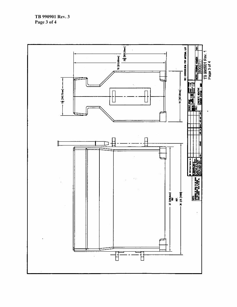
TB 990901 Rev. 3 Page 3 of 4

TB 990901 Rev. 3 Page 4 of 4

TB 001204 Rev. 1 Page 1 of 3
Narrow Steel Shelled-Quickchange Moveable Barrier
(NSS-QMB) Specification The Narrow Steel Shelled-Quickchange Moveable Barrier (NSS-QMB) is designed to meet the rigid requirements of deployment in moveable barrier applications where positive separation technology is required and where lane widths and lateral space may be limited, or maximum durability is required. Description The barrier elements shall be 32” (810 mm) high, 39” (1000 mm) in length, and 13” (330 mm) wide. The profile is 13” (330 mm) wide except for a heavy steel base, which shall be 24” (610 mm) wide. The barrier shall allow for the incorporation of a lane line at the intersection of the base and the vertical section. The small protrusion of the base shall provide an audible signal upon contact by an errant vehicle’s tire (Attachment Figure 1, B001204). The individual elements shall weigh approximately 1600 pounds (725 kg) and shall rest on four rubber feet to increase the coefficient of friction between the barrier element and the road surface. The barrier elements are connected in an end-to-end fashion with tensioning hinge mechanisms and steel pins that are at least 1.3 " (33 mm) in diameter. Each end of the NSS-QMB must be anchored to the roadway with an anchorage that is capable of reacting a 100,000-pound (450,000 Newton) tensile load in the barrier for NCHRP TL-3 installations or capable of at least a 50,000 pound (225,000 Newton) tensile load in the barrier for an NCHRP TL-2 installation, in order to perform with the minimum deflection characteristics. If the end of the NSS-QMB is not anchored to the roadway a minimum length of 80 sections must be deployed upstream of the point where minimum deflection is required for a TL-3 system, or 40 sections must be deployed upstream of the point where minimum deflection is required for a TL-2 system. Materials The primary elements of the NSS-QMB shall be constructed of ASTM, A-36 steel and high strength concrete. All external steel shall be hot dipped galvanized in accordance

TB 001204 Rev. 1 Page 2 of 3
with ASTM, A 123. All structural welds shall be continuous. The shell shall be constructed of 0.25” (6.4 mm) A-36 steel. System Requirements The NSS-QMB system, when installed in accordance with the manufacturers instructions, shall function as a longitudinal barrier. Narrow Steel Shelled Variable Length Barriers (NSS-VLBs) shall be added to the length of the NSS-QMB installation in order to allow a smooth lateral transfer through the Barrier Transfer Machine. The number and location of NSS-VLB units that shall be required will vary depending on specifics of the application, number and degree of curves, changes in elevation, etc.

TB 0
0120
4 R
ev. 1
Pa
ge 3
of 3