baseline spec template - nexrad radar operations … · web viewthe class 1 user's systems may...
TRANSCRIPT

Document Number 2620001OCode Identification 0WY55WSR-88D ROCBuild DateRPG Build 12.0 - DRAFT
INTERFACE CONTROL DOCUMENT FOR THE
RPG TO CLASS 1 USER
Prepared by:
WSR-88D Radar Operations Center1313 Halley CircleNorman, OK 73069
APPROVED FORUSE AS PRODUCTBASELINE &SUBMITTED BY: DATE:
Cheryl A. StephensonTeam Leader, Configuration ManagementWSR-88D Radar Operations Center
DISTRIBUTION STATEMENT A: Approved for public release; distribution unlimited.

INTERFACE CONTROL DOCUMENT FOR THE RPG TO CLASS 1 USER
2620001DOCUMENT REVISION RECORD FORM
REVISION - A B C D E F G H I J KRELEASED BY
ROC ROC ROC ROC ROC ROC ROC ROC ROC ROC ROC ROC
RELEASE DATE
03/01/96 06/26/98 09/11/01 01/27/02 06/19/02 12/29/02
06/13/03
01/30/04
7/29/04 4/13/05 02/08/06
5/25/07
EFFECTIVITY
03/01/96 06/26/98 09/11/01 01/27/02 06/19/02 12/29/02
06/13/03
01/30/04
7/29/04 4/13/05 02/08/06
5/25/07
AUTHORITY
F0048 F0095 F0103 F0158 F0164 F0174 F0182 F0185 F0186 F0209 F0210 0250
FAST TRACK
NO NO NO NO NO NO NO NO NO NO NO NO
REV HISTORY
BLD 9.0 BLD 10.0 OPEN BLD 1.0
RPG BLD 1.2
RPG BLD 2.0
RPG BLD 3.0
RPG BLD 4.0
RPG BLD 5.0
RPG BLD 6.0
RPG BLD 7.0
RPG BLD 8.0
RPG BLD 9.0
Section 1.0 - A B D ISection 2.0 - A D ISection 3.0 - A C D E F G H I J KAppendix A - A DAppendix B - A D I KOperating Procedures
- A D
Appendix C C D E G H IAppendix D D F GAppendix E J
R-1

REVISION L M N ORELEASED BY ROC ROC ROC ROCRELEASE DATE 03/25/0
803/03/09
11/04/09
EFFECTIVITY 03/25/08
03/03/09
11/04/09
AUTHORITY 0286 0349 0445 0389FAST TRACK NO NO NO NOREV HISTORY RPG
BLD 10.0
RPG Build 11.0
RPG Build 11.2
RPG Build 12.0
Section 1.0Section 2.0Section 3.0 L M N OAppendix AAppendix BOperating ProceduresAppendix C LAppendix DAppendix E
R-2

REVISION RECORD
Document Originally Released as 1208304 and then converted to ROC Document 2620001Supplement 123 July 1997
Insert RPGOP information in support of AWIPS program. Draft of section 3 to be released prior to incorporation of all information into next revision of ICD. (Pages are all identified with Supplement followed by section and page number)
Revision B Divide the document into two documents communication protocol and application layer. The communications protocol will be documented in 2620040, RPG X.25 Protocol ICD.Background maps have been removed since the open RPG does not distribute background maps.
Revision C Added Build 1.2 products. Added Appendix C on Data Transmission Rates.Revision D Added Build 2.0 products. Added Appendix D on bzip2 compression.Revision E Added Build 3.0 products.Revision F Added Build 4.0 products. Revision G Added Build 5.0 products.Revision H Added Build 6.0 products.Revision I Added Build 7.0 products.Revision J Added Build 8.0 products. Added Appendix E on RPG Generic Product
Format.Revision K Added Build 9.0 products.Revision L Added Build 10.0 products. Added VCP 211 to Appendix C.Revision M Added reference to CMD Generated Clutter Bypass Map to Table V and to
Figure 3-17 (Sheets 1 and 2).Revision N Added Build 11.2 products.Revision O Added Build 12.0 Dual Polarization products to Section 3.3.1.4, Table II, Table
IIa, Table III, Table V, Table VI, Table VIII and Table X. Added AVSET to Table V.
R-3

TABLE OF CONTENTS
1 SCOPE............................................................................................................................1-11.1 Identification...........................................................................................................1-11.2 System Overview.....................................................................................................1-1
1.2.1 RPG...................................................................................................................1-11.2.2 Class 1 Users/RPGOP.........................................................................................1-1
1.3 Document Overview................................................................................................1-12 REFERENCE DOCUMENTS..............................................................................................2-2
2.1 Government Documents..........................................................................................2-22.1.1 Specifications....................................................................................................2-2
2.2 Non-Government Documents..................................................................................2-22.2.1 Industry Standards............................................................................................2-2
3 APPLICATION LAYER.......................................................................................................3-13.1 RPG Message and Product Segmentation................................................................3-13.2 Operating Procedures..............................................................................................3-1
3.2.1 Initial Messages.................................................................................................3-13.2.1.1 General Status Message..............................................................................3-13.2.1.2 Alert Adaptation Parameters Message........................................................3-1
3.2.2 Requesting Weather Products...........................................................................3-13.2.2.1 Product Distribution and Availability...........................................................3-13.2.2.2 NEXRAD Message Code Definitions.............................................................3-23.2.2.3 NEXRAD Weather Product Code Definitions................................................3-23.2.2.4 Product Dependent Header Definitions.......................................................3-23.2.2.5 Requesting One-Time Products...................................................................3-23.2.2.6 Requesting Routine Products......................................................................3-23.2.2.7 Request Response Message........................................................................3-2
3.2.3 Alerting.............................................................................................................3-23.2.3.1 Alert Request Message................................................................................3-23.2.3.2 Alert Message.............................................................................................3-2
3.2.4 External Data Message......................................................................................3-33.2.4.1 Bias Table Message.....................................................................................3-3
3.2.5 Other Messages.................................................................................................3-33.2.5.1 Product List Message..................................................................................3-33.2.5.2 Radar Coded Message.................................................................................3-3
3.3 Message Description................................................................................................3-33.3.1 Graphic Product Message..................................................................................3-3
3.3.1.1 Product Description Block...........................................................................3-33.3.1.2 Product Symbology Block............................................................................3-43.3.1.3 Graphic Alphanumeric Block.......................................................................3-43.3.1.4 Tabular Alphanumeric Block........................................................................3-4
3.3.2 Stand-Alone Tabular Alphanumeric Product Message........................................3-53.3.3 Coordinate System............................................................................................3-6
Appendix A. Glossary..........................................................................................................A-1Appendix B. Radar Coded Message.....................................................................................B-1Appendix C. Data Transmission Characteristics...................................................................C-6Appendix D. Product Data Compression Using bzip2...........................................................D-1Appendix E. Generic Product Format....................................................................................E-1
INDEX OF FIGURES
Figure 3-3. Message Header.................................................................................................3-7Figure 3-4. Product Request Message (Sheet 1)...................................................................3-8
i

Figure 3-4. Product Request Message (Sheet 2).................................................................3-10Figure 3-5. Alert Request Message (Sheet 1).....................................................................3-23Figure 3-5. Alert Request Message (Sheet 2)...................................................................3-24Figure 3-6. Graphic Product Message (Sheet 1).................................................................3-26Figure 3-6. Graphic Product Message (Sheet 2)................................................................3-27Figure 3-6. Graphic Product Message (Sheet 3).................................................................3-28Figure 3-6. Graphic Product Message (Sheet 4).................................................................3-29Figure 3-6. Graphic Product Message (Sheet 5).................................................................3-30Figure 3-6. Graphic Product Message (Sheet 6).................................................................3-33Figure 3-6. Graphic Product Message (Sheet 7)................................................................3-40Figure 3-6. Graphic Product Message (Sheet 8)................................................................3-41Figure 3-6. Graphic Product Message (Sheet 9)................................................................3-42Figure 3-6. Graphic Product Message (Sheet 10)..............................................................3-43Figure 3-7 Linked Vector Packet - Packet Code 6 (Sheet 1)..............................................3-103Figure 3-7 Linked Vector Packet - Packet Code 9 (Sheet 2)..............................................3-103Figure 3-7. Linked Vector Packet - Packet Code 9 (Sheet 3).............................................3-104Figure 3-8. Unlinked Vector Packet - Packet Code 7 (Sheet 1).........................................3-105Figure 3-8. Unlinked Vector Packet - Packet Code 10 (Sheet 2).......................................3-106Figure 3-8. Unlinked Vector Packet - Packet Code 7 (Sheet 3)........................................3-107Figure 3-8. Unlinked Vector Packet - Packet Code 10 (Sheet 4)......................................3-108Figure 3-8a Contour Vector Packet - Packet Codes 0E03, 0802 and 3501 (Sheet 1).......3-109Figure 3-8a Contour Vector Packet - Packet Codes 0802 and 0E03 (Sheet 2).................3-110Figure 3-8a Contour Vector Packet - Packet Code 3501 (Sheet 3)...................................3-111Figure 3-8b. Text and Special Symbol Packets - Packet Code 1 (Sheet 1)........................3-112Figure 3-8b. Text and Special Symbol Packets - Packet Code 8 (Sheet 2)........................3-113Figure 3-8b. Text and Special Symbol Packets - Packet Code 2 (Sheet 3)........................3-114Figure 3-8b. Text and Special Symbol Packets - Packet Code 1 (Sheet 4).......................3-115Figure 3-8b. Text and Special Symbol Packets - Packet Code 2 (Sheet 5).......................3-116Figure 3-9. Map Message Packet - Packet Codes 0E23, 4E00, 3521 and 4E01 (Sheet 1).3-117Figure 3-9. Map Message Packet - Packet Codes 0E23, 4E00, 3521 and 4E01 (Sheet 2).3-118Figure 3-10. Radial Data Packet (16 Data Levels) - Packet Code AF1F (Sheet 1).............3-119Figure 3-10. Radial Data Packet (16 Data Levels) - Packet Code AF1F (Sheet 2).............3-120Figure 3-11. Raster Data Packet - Packet Codes BA0F and BA07 (Sheet 1)......................3-121Figure 3-11. Raster Data Packet - Packet Codes BA0F and BA07 (Sheet 2).....................3-122Figure 3-11a. Digital Precipitation Data Array Packet - Packet Code 17 (Sheet 1)...........3-123Figure 3-11a. Digital Precipitation Data Array Packet - Packet Code 17 (Sheet 2)...........3-123Figure 3-11b. Precipitation Rate Data Array Packet - Packet Code 18 (Sheet 1).............3-124Figure 3-11b. Precipitation Rate Data Array Packet - Packet Code 18 (Sheet 2)..............3-124Figure 3-11c. Digital Radial Data Array Packet - Packet Code 16 (Sheet 1).....................3-125Figure 3-11c. Digital Radial Data Array Packet - Packet Code 16 (Sheet 2).....................3-126Figure 3-12. Vector Arrow Data Packet - Packet Code 5..................................................3-127Figure 3-13. Wind Barb Data Packet - Packet Code 4......................................................3-128Figure 3-14. Special Graphic Symbol Packet - Packet Code 3 or 11, 12 or 26, 13 and 14 (Sheet 1)..........................................................................................................................3-129Figure 3-14. Special Graphic Symbol Packet - Packet Codes 15, 19, 23, 24 and 25 (Sheet 2)......................................................................................................................................... 3-130Figure 3-14. Special Graphic Symbol Packet - Packet Codes 3, 11, 12, 13, 14, 15, 19, 23, 24, 25 and 26 (Sheet 3).........................................................................................................3-131Figure 3-14. Special Graphic Symbol Packet - Packet Code 20 (Sheet 4).........................3-132Figure 3-15. Cell Trend Data Packet - Packet Code 21 (Sheet 1)......................................3-133Figure 3-15. Cell Trend Data Packet - Packet Code 21 (Sheet 2).....................................3-134Figure 3-15a. Cell Trend Volume Scan Times - Packet Code 22......................................3-135Figure 3-15b. SuperOb Wind Data Packet - Packet Code 27 (Sheet 1).............................3-136Figure 3-15b. SuperOb Wind Data Packet -- Packet Code 27 (Sheet 2)............................3-137Figure 3-15c Generic Data Packet - Packet Codes 28 and 29 (Sheet 1)..........................3-138
ii

Figure 3-16. Stand-Alone Tabular Alphanumeric Product Message.................................3-139Figure 3-17. General Status Message (Sheet 1)..............................................................3-144Figure 3-17. General Status Message (Sheet 2)..............................................................3-149Figure 3-18. Request Response Message (Sheet 1).........................................................3-150Figure 3-18. Request Response Message (Sheet 2).........................................................3-152Figure 3-19. Alert Message (Sheet 1)..............................................................................3-153Figure 3-19. Alert Message (Sheet 2)..............................................................................3-155Figure 3-20. Alert Adaptation Parameters Message (Sheet 1).........................................3-156Figure 3-20. Alert Adaptation Parameters Message (Sheet 2).........................................3-157Figure 3-21. Product List Message (Sheet 1)...................................................................3-158Figure 3-21. Product List Message (Sheet 2)....................................................................3-159Figure 3-22. Radar Coded Message..................................................................................3-161Figure 3-23. External Data Message...............................................................................3-162Figure 3-25. Bias Table Message (Sheet 1)......................................................................3-163Figure 3-25. Bias Table Message (Sheet 2).....................................................................3-165Figure E-1. Product Description Data Structure (Sheet 1)....................................................E-1Figure E-1. Product Description Data Structure (Sheet 2)....................................................E-3Figure E-1b. External Data Description Data Structure (Sheet 1).........................................E-4Figure E-1b. External Data Description Data Structure (Sheet 2).........................................E-5Figure E-2. Product Parameter Data Structure (Sheet 1)......................................................E-6Figure E-2. Product Parameter Data Structure (Sheet 2)......................................................E-6Figure E-3. Radial Component Data Structure (Sheet 1)......................................................E-8Figure E-3. Radial Component Data Structure (Sheet 2)......................................................E-8Figure E-4. Radial Information Data Structure (Sheet 1)......................................................E-9Figure E-4. Radial Information Data Structure (Sheet 2)......................................................E-9Figure E-5. Grid Component Data Structure (Sheet 1).........................................................E-9Figure E-5. Grid Component Data Structure (Sheet 2).......................................................E-10Figure E-6. Area Component Data Structure (Sheet 1).......................................................E-10Figure E-6. Area Component Data Structure (Sheet 2).......................................................E-11Figure E-7a. Geographic Location Data Structure (Sheet 1)...............................................E-11Figure E-7a. Geographic Location Data Structure (Sheet 2)...............................................E-11Figure E-7b. X/Y Location Data Structure (Sheet 1)............................................................E-11Figure E-7b. X/Y Location Data Structure (Sheet 2)............................................................E-12Figure E-7c. Az/Ran Location Data Structure (Sheet 1)......................................................E-12Figure E-7c. Az/Ran Location Data Structure (Sheet 2)......................................................E-12Figure E-8. Text Component Data Structure (Sheet 1).......................................................E-12Figure E-8. Text Component Data Structure (Sheet 2).......................................................E-12Figure E-9. Table Component Data Structure (Sheet 1).....................................................E-13Figure E-9. Table Component Data Structure (Sheet 2).....................................................E-13Figure E-10. Event Component Data Structure (Sheet 1)...................................................E-13Figure E-10. Event Component Data Structure (Sheet 2)...................................................E-14Figure E-11. Binary Data Data Structure (Sheet 1).............................................................E-14Figure E-11. Binary Data Data Structure (Sheet 2).............................................................E-14Figure E-12. String Data Structure (Sheet 1)......................................................................E-14Figure E-12. String Data Structure (Sheet 2)......................................................................E-15
INDEX OF TABLES
Table II. NEXRAD Message Code Definitions......................................................................3-11Table IIa. Product Dependent Halfword Definitions for Product Request Message............3-12Table III. Message Codes for Products...............................................................................3-15Table IV. Alert Categories and Threshold Codes................................................................3-25Table V. Product Dependent Halfword Definition for Product Description Block................3-44Table VI. Product Dependent Definition for Product Symbology Block..............................3-68Table VII. Product Dependent Definition for Graphic Alphanumeric Block.........................3-75Table VIII. Product Dependent Definition for Tabular Alphanumeric Block........................3-84
iii

Table IX. Product Dependent Definition for Stand-Alone Tabular Alphanumeric Block....3-140Table X. Product List Message Parameter Definition.......................................................3-160Table XI. Application Data Sizes...........................................................................................C-6Table XII. VCP 11 Product Size.............................................................................................B-7Table XIII. VCP 12 Product Size..........................................................................................B-12Table XIV. VCP 121 Product Size........................................................................................B-16Table XV. X-25 Bandwidth Estimation for an Example Class 1 User RPS List (See Note 1).B-20Table XVI. - VCP 211 Product Sizes....................................................................................B-22
iv

1 SCOPE
1.1 IdentificationThis document defines the interface connection between the Next Generation Weather Radar (NEXRAD) Radar Product Generation Group (RPG) and a Class 1 User or Radar Products Generator Operator's Position (RPGOP). RPG refers to the RPG equipment, 2830007, Pt 1 and Radar Product Generation Program CPCI-03, 2820003, Part 1.
1.2 System Overview
1.2.1 RPGThe RPG system is one component of the WSR-88D system. The WSR-88D system is used to gather weather information to be distributed to the National Weather Service (NWS), the Federal Aviation Administration (FAA), the Department of Defense (DOD), and the general public. The RPG may be located with the RDA system in a shelter at the WSR-88D site, or may be located remotely, and communicate with the RDA through a wideband communication link. It is responsible for Base Data Ingest, Product Generation, Product Storage, Hydrometeorological Processing, Product Distribution, and Base Data Distribution.
1.2.2 Class 1 Users/RPGOPThe Class 1 user's systems may be located anywhere. They communicate with the RPG via dedicated phone lines or LAN connection. These systems issue product requests to the RPG, receive the products from the RPG, and display the products to an operator.
1.3 Document OverviewThis document defines the application layer interface between the RPG and Class 1 users/RPGOP. For this interface, this document identifies applicable standards and defines messages, product format and meaning of the packet codes. This ICD is not intended to serve as a document concerning the applicable standards. That is, the reader is assumed to be generally knowledgeable of the contents, terminology, etc., of the standards. Distribution of this document is unrestricted.This document is organized in 3 sections and five appendices:
Section 1 provides information regarding the identification, scope, purpose and organization of this document.Section 2 contains information about documentation relevant to this ICD, including applicable, and information documents.Section 3 provides an overview of the application interface, operating procedures and message formats.Appendix A contains a list of abbreviations, acronyms, and selected definitions.Appendix B contains a detailed description of the Radar Coded Message.Appendix C contains data transmission characteristics.Appendix D contains product data compression using BZIP2.Appendix E contains a description of the Generic Product Format.
2 REFERENCE DOCUMENTS
2.1 Government Documents
2.1.1 Specifications2830007, Pt 1 Prime Item Development Specification for
1

RPG Equipment (B1, CI-07)
2810000F WSR-88D System Specification
2820003B,Pt1 Computer Program Development Specification for Radar Product Generation Program (SRS, CPCI-03)
2620003B Product Specification Interface Control Document
2620037 RPG X.25 Protocol Interface Control Document
2620041B TCP/IP Interface Control Document
Source: ROC Configuration ManagementWSR-88D Radar Operations Center1313 Halley CircleNorman, OK 73069
2.2 Non-Government Documents
2.2.1 Industry StandardsReference Number Title
IEEE 754-1985 IEEE Standard for Binary Floating-Point Arithmetic
RFC 1832 XDR: External Data Representation Standard
2

3 APPLICATION LAYERThe RPG application layer interface provides Class 1 users or RPGOPs with status messages and meteorological products.
3.1 RPG Message and Product SegmentationRPG transport processing segments each application product larger than 10K bytes into 10K byte blocks of user data to be sent to the Network Layer. Therefore, the RPG application Message Header block is always required to correctly reassemble products larger than 10K bytes, regardless of the underlying network. [Note: 1K byte =1024 bytes].
3.2 Operating ProceduresOnce the Class 1/RPGOP link is established and logically connected, application level message exchange may proceed. These messages consist of NEXRAD system status messages transmitted to the user, requests for weather product data transmitted from the user to the RPG, and weather product data transmitted from the RPG to the Class 1 user/RPGOP. See RPG X.25 Protocol ICD, 2620037, or RPG TCP/IP, 2620041, for information on establishing the appropriate link.
3.2.1 Initial Messages
3.2.1.1 General Status MessageUpon connection, the first Product Data Level message transmitted by the RPG to a Class 1 user/RPGOP is the General Status Message. The General Status Message describes the state of the Radar Acquisition (RDA) and RPG. This data informs the Class 1 user/RPGOP about operational modes, the scan strategy and equipment status of the RDA and RPG. Figure 3-17 provides a graphic representation of this message. Field identifiers are described (in halfword order) along with their respective units and range in this figure. As the state of the NEXRAD system changes over the life of the communications session, the Class 1 user/RPGOP will be kept up to date by transmission of a new General Status Message.
3.2.1.2 Alert Adaptation Parameters MessageThe RPG transmits an Alert Adaptation Parameters Message to the Class 1 user/RPGOP after the initial General Status Message. The Class 1 user/RPGOP will also receive this message if any changes are made to the Alert Thresholds or Product Alert Pairing by the RPG. The Alert Adaptation Parameters Message is shown in Figure 3-20.
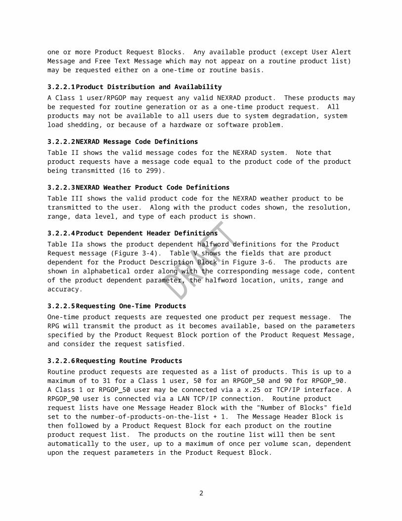
3.2.2 Requesting Weather ProductsRequesting Weather Product Data over a Class 1 user/RPGOP dedicated line is accomplished by the Class 1 user/RPGOP sending a Product Request Message as defined in Figure 3-4. It consists of one Message Header Block, followed by one or more Product Request Blocks. Any available product (except User Alert Message and Free Text Message which may not appear on a routine product list) may be requested either on a one-time or routine basis.
3.2.2.1 Product Distribution and AvailabilityA Class 1 user/RPGOP may request any valid NEXRAD product. These products may be requested for routine generation or as a one-time product request. All products may not be available to all users due to system degradation, system load shedding, or because of a hardware or software problem.
1

3.2.2.2 NEXRAD Message Code DefinitionsTable II shows the valid message codes for the NEXRAD system. Note that product requests have a message code equal to the product code of the product being transmitted (16 to 299).
3.2.2.3 NEXRAD Weather Product Code DefinitionsTable III shows the valid product code for the NEXRAD weather product to be transmitted to the user. Along with the product codes shown, the resolution, range, data level, and type of each product is shown.
3.2.2.4 Product Dependent Header DefinitionsTable IIa shows the product dependent halfword definitions for the Product Request message (Figure 3-4). Table V shows the fields that are product dependent for the Product Description Block in Figure 3-6. The products are shown in alphabetical order along with the corresponding message code, content of the product dependent parameter, the halfword location, units, range and accuracy.
3.2.2.5 Requesting One-Time ProductsOne-time product requests are requested one product per request message. The RPG will transmit the product as it becomes available, based on the parameters specified by the Product Request Block portion of the Product Request Message, and consider the request satisfied.
3.2.2.6 Requesting Routine ProductsRoutine product requests are requested as a list of products. This is up to a maximum of to 31 for a Class 1 user, 50 for an RPGOP_50 and 90 for RPGOP_90. A Class 1 or RPGOP_50 user may be connected via a x.25 or TCP/IP interface. A RPGOP_90 user is connected via a LAN TCP/IP connection. Routine product request lists have one Message Header Block with the "Number of Blocks" field set to the number-of-products-on-the-list + 1. The Message Header Block is then followed by a Product Request Block for each product on the routine product request list. The products on the routine list will then be sent automatically to the user, up to a maximum of once per volume scan, dependent upon the request parameters in the Product Request Block.
3.2.2.7 Request Response MessageIf the RPG is unable to distribute a product to the user, or receives an invalid message, or request for an invalid product, the RPG will transmit a Request Response message as shown in Figure 3-18. This message describes the error condition, sequence number (if applicable) of the request that generated the response, and the product or message code of the message in question. All of the error conditions of this message nullify the product request for the reasons given in the message, with the exception of "Available Next Volume Scan" and "One-time Request Generation Process Faulted" errors, which inform the Class 1 user/RPGOP that the product will be sent in the next volume scan.
3.2.3 Alerting
3.2.3.1 Alert Request MessageAlert areas are defined by the Class 1 user/RPGOP and transmitted to the RPG via the Alert Request Message. The format for the message is shown in Figure 3-5. Alert categories and threshold codes are given in Table IV.
2

3.2.3.2 Alert MessageThe Class 1 User/RPGOP is notified when the alert condition is first detected by the RPG, and when the alert condition ends, via the Alert Message. The Alert Message format is shown in Figure 3-19.
3.2.4 External Data MessageExternal Data Messages are those importing meteorological, hydrometeorological, or other scientific or mathematical information into the RPG from the Class 1 user/RPGOP. In all such messages, the message code will be set to 5 in the Message Header Block (Figure 3-2), though individual messages will vary in content and format. The specific type of external data message will be indicated by the setting of the Block ID in the body of the message block that follows. The format of the message is shown in Figure 3-23.
3.2.4.1 Bias Table MessageThis message contains a table of bias adjustment factors and related information determined at the Class 1 user/RPGOP site from rain gage vs. radar-estimated rainfall amounts over various memory timespans. The information is used to perform a mean-field bias adjustment upon precipitation accumulation products in the RPG. The Bias Table Message is indicated by a Message Code of 15. The format of the message is shown in Figure 3-25.
3.2.5 Other Messages
3.2.5.1 Product List MessageThe Product List Message defined in Figure 3-21 lists all products commanded for generation by the MSCF operator. A Product List Message is requested by sending a Message Header Block (Figure 3-3) to the RPG and setting the message code to 8. This message was removed in Build 12. Request for message code 8 in Build 12 and later, will result in the RPG transmitting General Status Message.
3.2.5.2 Radar Coded MessageThe Radar Coded Message (RCM) is produced at the RPG for distribution to users. The format of the RCM is provided in Figure 3-22 and Appendix B. A more complete description of the product can be found in the Product Specification ICD (2620003).
3.3 Message Description
3.3.1 Graphic Product MessageThe RPG transmits products to the Class 1 User/RPGOP by using the Graphic Product message shown in Figure 3-6. The message consists of several blocks. Not all products require all blocks; however, the blocks are always transmitted in the order shown in Figure 3-6. One Header block and one Product Description block always precede the product. Products consist of one Product Symbology block (Block ID = 1), and zero or one of each of the Graphic Alphanumeric (Block ID = 2), and Tabular Alphanumeric blocks (Block ID = 3). The number of the last two blocks in each message used is product dependent.
3.3.1.1 Product Description BlockThe Product Description block for product data transmission is shown in Figure 3-6 (sheets 2, 6, and 7). Many field identifiers in the Product Description block are product dependent and therefore change depending upon the product being transmitted. Refer to Table V for the definitions of these fields and their corresponding products. The Products are listed by product name, in alphabetical order. As shown in Figure 3-6 (sheet 2), halfwords 55-60 contain offsets from the beginning of the message header (halfword 1) to the (-1) divider of
3

each block indicated. If a product being transmitted does not require a block, or the data is not available, the offset to the block in question is set to zero. The first offset (halfword 55-56) is the offset to the Product Symbology block. The second offset (halfword 57-58) is the offset to the (-1) divider of the Graphic Alphanumeric block (Block ID = 2). The third offset is the offset to the Tabular Alphanumeric block (Block ID = 3).Some products, by virtue of their size, require data compression. If a product is compressed, all product data following the Product Description block are compressed. Product dependent parameters defined within the Product Description block specify the compression method and size of the uncompressed product. The length of message in the Message Header block refers to the size of the compressed product. Refer to Table V for Product Description block definitions for compressed products. Appendix D describes the data compression method.
3.3.1.2 Product Symbology BlockThe Product Symbology block is block ID number 1 and is shown in Figure 3-6 (sheets 3 and 8). It is always numbered as 1. If it is available in a product, it will always follow the Product Description block. In general, this block contains display data packets that make up the geographic display of the product. These packets contain vectors, text and special character symbols, map data, radial data, raster data, precipitation data, vector arrow data, wind barb data, and special graphic symbols. The packet formats are defined in Figures 3-7 through 3-15c. The Symbology block may, depending upon the product, have multiple "layers" of packets. This is done only in products that have both image type data, mixed with non-image type data. An example of this is a Combined Moment product. It has reflectivity displayed as an image and vector arrow data that is defined with vector arrow packets. The layers are started with the (-1) divider. The product dependent data identified in Table VI is incorporated into the Product Symbology Block.
3.3.1.3 Graphic Alphanumeric BlockThe Graphic Alphanumeric block is block ID number 2. It is the block in which display packets are defined to cause the storm related data to be displayed at the top of the geographic screen to amplify the corresponding graphic displayed symbology. The format of this block is shown graphically in Figure 3-6 (sheets 4 and9). The only products for which this block is formatted are the following:
Product Code Product Name31 User Selectable Precipitation35-38, 95-98 Composite Reflectivity, Composite
Reflectivity Edited for AP58 Storm Tracking Information59 Hail Index60 Mesocyclone61 Tornado Vortex Signature139 Mesocyclone Rapid Update141 Mesocyclone Detection143 Tornado Vortex Signature Rapid Update
The actual data within this block is a series of text packets that format the line data into 5 lines. The number of pages is data dependent. The text packet format used for the attributes is packet number 8 shown in Figure 3-8. Notice that I-start and J-start are defined as 1/4 km from the radar. The Graphic Attributes packets are not geographic, but are actual screen coordinates. Included in the text packet for each page of Attribute data is a series of vector packets to draw the grid lines. The vector packets used are shown in Figure 3-7. The product dependent data identified in Table VII is incorporated into the Graphic Alphanumeric Block.
4
3.3.1.4 Tabular Alphanumeric BlockThe Tabular Alphanumeric block for product data transmission is Block ID number 3. The format of this block is shown graphically in Figure 3-6 (sheets 5 and 10). It is always numbered 3 even though it may not be the third block in the product. The following products have a paired-alphanumeric product that is encoded as Block 3 (Figure 3-6, sheet 7). The paired-alphanumeric product has a second Header and Product Description block as shown in the figure. The products that have Block ID 3 are as follows:Product Code Product Name Block 3 Message Code48 VAD Wind Profile 10058 Storm Tracking
Information101
59 Hail Index 10260 Mesocyclone 10361 Tornado Vortex
Signature104
78 Surface Rainfall Accumulation (1 hour)
107
79 Surface Rainfall Accumulation (3 hours)
108
80 Storm Total Rainfall Accumulation
109
132 Clutter Likelihood Reflectivity
110
133 Clutter Likelihood Doppler
111
139 Mesocyclone Rapid Update
139
141 Mesocyclone Detection 141143 Tornado Vortex
Signature Rapid Update143
171 Storm Total Accumulation
171
The second header of the alphanumeric product is exactly the same as the header at the beginning of the message, except that the Message Code is as defined above. The Data portion of the alphanumeric product is ASCII text formatted into pages of 17 lines of 80-character data. Each page is separated by the (-1) divider. Alphanumeric products containing this block have it as the last block of the product message. The product dependent data identified in Table VIII is incorporated into the Tabular Alphanumeric Block.
3.3.2 Stand-Alone Tabular Alphanumeric Product MessageFigure 3-16 defines the Stand-Alone Tabular Alphanumeric Product Message. This message is used for products that are completely alphanumeric, and are not paired as described in subsection 3.2.1.4. These products do not contain a symbology block. The Stand-Alone Tabular Alphanumeric Products are: User Alert Message (product 73), Storm Structure (product 62), Free Text Message (product 75), PUP Text Message (product 77) and Supplemental Precipitation Data (product 82). The format of the Product Description block is identical to that for the Graphic Product Message, except the first offset is to the (-1) divider shown in Figure 3-16. The product dependent data identified in Table IX is incorporated into the Stand-Alone Tabular Alphanumeric Product Message.
5

3.3.3 Coordinate SystemThree coordinate systems are supported for the expression of weather information:
Geographic Cartesian Polar Screen CartesianA Geographic Cartesian coordinate system with origin at the radar and positive directions of North (up), and East (right) are supported. The coordinate system has a range of 512 kilometers with 1/4-kilometer resolution. Specifically, I (right) and J (up) coordinates range from -2048 to +2048 with negative coordinates in two complement forms. Vectors are represented in this coordinate system.A Polar coordinate system with origin at the radar and 0-degree radial North (up) is supported. The range coordinate covers from 0 to 460 kilometers with 1/4-kilometer resolution. The azimuth coordinate covers 0 to 360 degrees with 0.1-degree resolution. This resolution is necessary to achieve 0.1-degree resolution used system wide. Positive angles are clockwise. Specifically, theta coordinates range from 0 to 360 degrees. Images are represented in the Polar coordinate system. Each point in the display is represented by a display value.A Screen Cartesian coordinate system with origin at the upper left corner and positive directions of X to the right and Y down are supported. The X coordinate ranges from 0 to 639 pixels and the Y-coordinate ranges from 0 to 511 pixels. X can be expressed in 10 bits and Y in 9 bits. The screen coordinate system is used to identify the location of text on the screen.
6

MSB HALFWORD LSB
MESSAGE MESSAGE CODE 01HEADER DATE OF MESSAGE 02BLOCK TIME OF MESSAGE (MSW) 03
TIME OF MESSAGE (LSW) 04LENGTH OF MESSAGE (MSW) 05LENGTH OF MESSAGE (LSW) 06SOURCE ID 07DESTINATION ID 08NUMBER OF BLOCKS 09
HALFWORD FIELDNAME TYPE UNIT
SRANGE
PRECISION/ACCURACY
REMARKS
01 Message Code INT*2 N/A -131 to -16,0 to +211
N/A NEXRAD Message Code defined in Table II
02 Date of Message INT*2 Julian Date
1 to 32,767
1 Modified Julian Date at time of transmission (number of days since 1 January 1970, where 1=1 January 1970). To obtain actual Julian Date, add 2,440,586.5 to the modified date
03-04 Time of Message INT*4 Seconds
0 to 86,399
1 Number of seconds after midnight, Greenwich Mean Time (GMT).
05-06 Length of Message
INT*4 N/A 18 to 1329270
1 Number of bytes in message including header
07 Source ID INT*2 N/A 0 to 999 1 Source (originators') ID of the sender
08 Destination ID INT*2 N/A 0 to 999 1 Destination ID (receivers') for message transmission
09 Number Blocks INT*2 N/A 1 to 51 1 Header Block plus the Product Description Blocks in message
Figure 3-3. Message Header
MSB HALFWORD LSB
MESSAGE
7

HEADERBLOCK(see Figure 3-3)
PRODUCT (-1) DIVIDER 10REQUEST LENGTH OF BLOCK 11BLOCK PRODUCT CODE 12
FLAG BITS 13SEQUENCE NUMBER 14NUMBER OF PRODUCTS 15REQUEST INTERVAL 16VOLUME SCAN DATE 17VOL SCAN START TIME (MSW) 18VOL SCAN START TIME (LSW) 19PRODUCT DEPENDENT 20" 21" 22" 23" 24" 25
Figure 3-4. Product Request Message (Sheet 1)
8

HALFWORD FIELDNAME TYPE UNITS RANGEPRECISION/ACCURACY REMARKS
10 Block Divider
INT*2 N/A -1 N/A Value of -1 used to delineate the Header from the Product Description Block(s)
11 Length of Block
INT*2 N/A 32 1 Number of bytes in block, including block divider, in the Product Description Block
12 Product Code
INT*2 N/A 16 to 2000 N/A Internal NEXRAD product code corresponding to a weather product in Table I
13 Flag Bits INT*2 N/A 0,1/bit N/A Bit # Value Meaning0 1 High Priority0 0 Low Priority1 1 Map Requested(Bit 0=MSB)
14 Sequence Number
INT*2 N/A 1 to 32,767
1 Monotonically increase for tracking of request
15 Number of Products
INT*2 N/A -1, 1 to 9 1 -1 for continuous (RPS) product transmission. 1 to 9 for one-time requests, when Volume Scan Start Time of Product (halfwords 18, 19) is = -1 (equivalent to PUP Repeat Count).
NOTE: For RPS requests, the number of products requested is determined from the Number of Blocks fields of the Message Header.
16 Request INT*2 N/A 1 to 9 1 If Volume Scan Start
9

HALFWORD FIELDNAME TYPE UNITS RANGEPRECISION/ACCURACY REMARKS
Interval Time of Product is >=0 or -2, then Request Interval is 1. If Volume Scan Start Time of Product is = -1, then the range is 1 to 9 and corresponds to the interval of the number of scans to send the product, where:1 = every volume scan2 = every other volume scan...9 = every ninth volume scan
17 Volume Scan Date of Product*
INT*2 Julian Date
0 to 32,767
1 Modified Julian date at beginning of volume scan
18-19 Volume Scan Start Time of Product*
INT*4 Seconds
-2 to 86,399
1 Seconds after Midnight (Greenwich Mean Time)** or-1 requests current product-2 requests latest available product**
20-25 Product Dependent
INT*2 N/A N/A N/A See Table II-A
Figure 3-4. Product Request Message (Sheet 2)
*Volume scan date is only applicable for one-time product requests that have a Volume Scan Start Time in the range [0, 86399]. If a volume scan date and time are specified, it corresponds to the volume scan start date and time that is searched for that product.**For one-time product requests, if specifying the volume scan date and time or latest available and the product has elevation parameters then only the specific angle is allowed in the request. The feature described in Note 9 will result in a Request Response Message indicating Invalid Product Parameters.
10
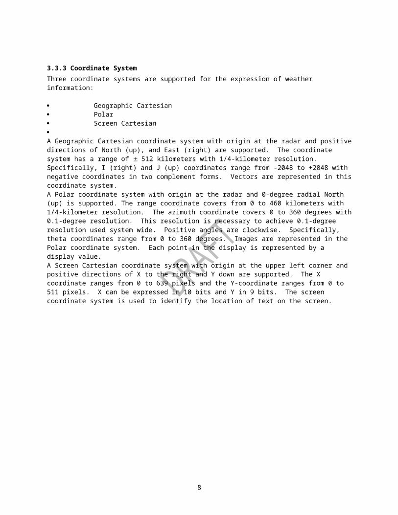
Table II. NEXRAD Message Code Definitions
MESSAGE CODE MESSAGE TYPE
FIGURE
0,13 1 2 3 4 5 6 7 8 9 10 11 12 14 15
Product Request, Product Request CancelSpareGeneral StatusRequest ResponseMaximum Connection Time Disable RequestExternal Data MessageAlert Adaptation Parameter MessageAlert Request MessageProduct ListAlert MessageSpareSign-on Request Message (Dial -up Users)SpareSpareBias Table Message
3-4 -3-173-18N/A3-233-203-53-213-19-N/A--3-25
16 to 111112 to 131 132-134 135136 to 138139-143
Products (See Table III for individual Product Codes)Reserved for future ProductsProducts (See Table III for Individual Product Codes)Reserved for future ProductProducts (See Table III for Individual Product Codes)Reserved for future Products
144-151 Products (See Table III for Individual Product Codes)152 Reserved for future Products153-155 Super Resolution156, 157 NTDA Products158-179 Dual Polarization Products (See Table III for Individual
Product Codes) Codes 167-168, 178 and 179 are reserved for future Dual Pol Base, and QPE products, respectively.
180-193 Reserved for future Products194 Base Reflectivity Data Array (DoD Version)195-198 Reserved for future Products199 Base Velocity Data Array (DoD Version)200-299 Reserved for future Products Negative
Annotations have a negative message code equal in magnitude to that of the Product being annotated
11

Table IIa. Product Dependent Halfword Definitions for Product Request Message
PRODUCT NAME MSG CODE(s) HALFWORD
CONTENT UNITS RANGE
ACCURACY/PRECISION
Base Products, ITWS Digital Base Velocity, Clutter Likelihood (Reflectivity and Doppler), Meso Rapid Update, NTDA (EDR and EDC)
16, 17, 18, 19,20, 21, 22, 23,24, 25, 26, 27,28, 29, 30, 93, 94, 99, 132, 133, 139, 156, 157, 194, 199
Elevation Angle
Degrees
-1.0 to 45.0
.1, Note 1, 9
Cross Section 50, 51, 85, 86
20 21 22 23
Azimuth of Point 1 Range of Point 1 Azimuth of Point 2 Range of Point 2
Degree Nmi Degree Nmi
0 to 359.9 0 to 124.0 Same as Point 1 Same as Point 1
.1, Note 1 .1, Note 1 .1, Note 1 .1, Note 1
Storm RelativeMean RadialVelocity Region
55 20
21
22 23 24
Azimuth of Window Center Range of Window Center Elevation Angle Storm Speed Storm Direction
Degree
Nmi
Degree Knots Degrees
0 to 359.9
0 to 124.0
-1.0 to 45.0 0 to 99.9 0 to 359.9
.1, Note 1
.1, Note 1
.1, Note 1,9 .1, Note 1,2 .1, Note 1
Storm RelativeMean RadialVelocity Map
56 22 23 24
Elevation Angle Storm Speed Storm Direction
Degree Knots Degrees
-1.0 to 45.0 0 to 99.9 0 to 359.9
.1, Note 1,9 .1, Note 1,3 .1, Note 1
VAD 84 22 Altitude K Feet
0 to 70
1
User SelectablePrecipitation (Note 5)
31 20 21
End Hour Time Span
Hours Hours
-1 to 23, 1 to 24
1, Note 6 1
UserSelectable Layer
137 20 21
Bottom Altitude of Layer
K Feet K
0 to 69 1
1 1, Note 8
12

PRODUCT NAME MSG CODE(s) HALFWORD
CONTENT UNITS RANGE
ACCURACY/PRECISION
CompositeReflectivity
Top Altitude of Layer
Feet to 70
Clutter Filter Control(Note 5)
34 20 Bit Map N/A
0,1 bit
N/A,Note 7
Tornado Vortex Signature Rapid Update
143 22 Elevation Angle
Degrees
-1.0 to 45.0
.1, Note 1,9
Digital Mesocyclone Detection
149 22 Elevation Angle
Degree
-1.0 to + 45.0
.1, Note 1,9
User Selectable Snow Accumulations (Note 5)
150, 151 20 21
End Hour Time Span
Hours Hours
-1 to 23 1 to 30
1, Note 6 1
Super Resolution Base Products (R/V/SW)
153, 154, 155
22 Elevation Angle
Degrees
-1.0 to 45.0
.1, Note 1,9
Differential Reflectivity
158, 159 22 Elevation Angle Degree -1.0 to + 45.0
.1, Note 1,9
Correlation Coefficient
160, 161 22 Elevation Angle Degree -1.0 to + 45.0
.1, Note 1,9
Specific Differential Phase
162, 163 22 Elevation Angle Degree -1.0 to + 45.0
.1, Note 1,9
Hydrometeor Classification
164, 165 22 Elevation Angle Degree -1.0 to + 45.0
.1, Note 1,9
Melting Layer 166 22 Elevation Angle Degree -1.0 to + 45.0
.1, Note 1,9
Digital User-Selectable Accumulation (Note 5)
173 20
End Time Time Span
Mins Mins
-1 to 1439 15 to 1440
1, Note 6
Note 1. Scaled Integer.Note 2. A value of -1 indicates that the storm motion is that of the storm closest to the window center.Note 3. A value of -1 indicates that the storm motion is that of the vector average of all currently identified storms.Note 4. Defines up to eight user selected elevation angles available in the current scan strategy. Scan strategy may contain 20 cuts. Each elevation cut selection is represented by a unique bit setting. Bit 1 of halfword 23 corresponds to elevation cut #l. Bit 4 of halfword 24 corresponds to elevation cut #20. Bit 0 of halfword 23 is the MSB and is not used.Note 5. One-time requests for this product should use the "latest available" request option. That is, place -2 in the volume scan start time field (halfword 18-19).Note 6. A value of -1 indicates that the end time will be the time of the most recent hourly update.Note 7. This halfword defines the clutter map segment number (both Version 0 and Version 1 of the CFC product) and channel type (Version 0 only). For Version 0, bit 15 (bit 0 = MSB)
13

defines the channel type. If bit 15 is 0, then the surveillance channel map is requested. If bit 15 is 1, then the Doppler channel map is requested. For both Version 0 and 1, bits 14 through 10 specify elevation segment numbers 1 through 5, respectively. Set the bit number of the segment being requested. Segment 1 is the lowest clutter filter map elevation segment, segment 5 is the highest clutter filter map elevation segment. For Version 1, bit 15 is ignored for any CFC product request.Note 8. Minimum layer thickness is 1 K FeetNote 9. Bits 0-12 (bit 0 is LSB) of halfword represents scaled elevation angle. For elevation angles >= 0, the elevation angle is denoted degrees*10. For elevation angles < 0, the angle is denoted 3600 + degrees*10.
Bits 13-15 have special meaning. If bits 13-15 are not set, bits 0-12 denote elevation angle as described above. Bit 15 is reserved for future use and should never be set. If bit 14 is set (bits 15 and 13 not set) and bits 0-12 not set, then all elevation angles of the volume coverage pattern are requested. If bit 14 is set (bits 15 and 13 not set), bits 0-12 may be used to denote elevation angle as described above. In this case, all elevation angles of the volume coverage pattern matching the specified elevation angle are requested. If bit 13 is set (bits 15 and 14 not set), then all elevation angles at or below the angle specified by bits 0-12 are requested. If bit 13 and 14 are set (bit 15 is not set), then 0-12 specifies an elevation cut number. The first N cuts (where N = cut number) are requested.
If the elevation parameter specifies multiple requests, each request counts against the maximum product count specified for the requestor. This check is only done when the request is first received at the RPG.
14

Table III. Message Codes for Products
CODE NTR PRODUCT NAME RESOLUTION RANGE DATA LEVEL
MESSAGE FORMAT
16 1 Base Reflectivity .54 x 1 Nmi x Deg
124 8 Radial Image
17 1 Base Reflectivity 1.1 x 1 Nmi x Deg
248 8 Radial Image
18 1 Base Reflectivity 2.2 x 1 Nmi x Deg
248 8 Radial Image
19 1 Base Reflectivity .54 x 1 Nmi x Deg
124 16 Radial Image
20 1 Base Reflectivity 1.1 x 1 Nmi x Deg
248 16 Radial Image
21 1 Base Reflectivity 2.2 x 2 Nmi x Deg
248 16 Radial Image
22 2 Base Velocity .13 x 1 Nmi x Deg
32 8 Radial Image
23 2 Base Velocity .27 x 1 Nmi x Deg
62 8 Radial Image
24 2 Base Velocity .54 x 1 Nmi x Deg
124 8 Radial Image
25 2 Base Velocity .13 x 1 Nmi x Deg
32 16 Radial Image
26 2 Base Velocity .27 x 1 Nmi x Deg
62 16 Radial Image
27 2 Base Velocity .54 x 1 Nmi x Deg
124 16 Radial image
28 3 Base Spectrum Width
.13 x 1 Nmi x Deg
32 8 Radial Image
29 3 Base Spectrum Width
.27 x 1 Nmi x Deg
62 8 Radial Image
30 3 Base Spectrum Width
.54 x 1 Nmi x Deg
124 8 Radial Image
31 32 User Selectable Storm Total Precipitation
1.1 x 1 Nmi x Deg
124 16 Radial Image/Geographic Alpha
32 33 Digital Hybrid Scan Reflectivity
.54 x 1 Nmi x Deg
124 256 Radial Image
33 33 Hybrid Scan Reflectivity
.54 x 1 Nmi x Deg
124 16 Radial Image
34 34 Clutter Filter Control
1 x 1.4 Km x Deg (Ver. 0)1 x 1.0 Km x Deg (Ver. 1)
124 8 (Ver. 0)4 (Ver. 1)
Radial Image
35 6 Composite Reflectivity
.54 x .54 Nmi x Nmi
124 8 Raster Image/Non-geographic Alpha
36 6 Composite Reflectivity
2.2 x 2.2 Nmi x Nmi
248 8 Raster Image/Non-geographic
15

CODE NTR PRODUCT NAME RESOLUTION RANGE DATA LEVEL
MESSAGE FORMATAlpha
37 6 Composite Reflectivity
.54 x .54 Nmi x Nmi
124 16 Raster Image/Non-geographic Alpha
38 6 Composite Reflectivity
2.2 x 2.2 Nmi x Nmi
248 16 Raster Image/Non-geographic Alpha
39 Spare40 Spare41 8 Echo Tops 2.2 x 2.2 Nmi x
Nmi 124 16 Raster Image
42 Spare43 Spare44 Spare45 Spare46 Spare47 Spare48 12 VAD Wind
Profile5 Knots N/A 5 Non-geographic
Alphanumeric49 Spare 16 Raster
Image/Non-geographic Alphanumeric
50 14 Cross Section (Reflectivity)
.54 Horizontal x .27 Vert Nmi x Nmi
124 16 Raster Image (Reflectivity)
51 14 Cross Section (Velocity)
.54 Horizontal x .27 Vert Nmi x Nmi
124 16 Raster Image (Velocity)
52 Spare53 Spare54 -------------------------Reserved---------------------------------------------------------------------------55 16 Storm Relative
Mean Radial Velocity
.27 x 1 Nmi x Deg 27 16 Radial Image (Region)
56 16 Storm Relative Mean Radial Velocity
.54 x 1 Nmi x Deg 124 16 Radial Image (Map)
57 17 Vertically Integrated Liquid
2.2 x 2.2 Nmi x Nmi
124 16 Raster Image
58 18 Storm Tracking Information
N/A 248 N/A Geographic and Non-geographic Alpha
59 19 Hail Index N/A 124 N/A Geographic and Non-geographic Alpha
60 20 Mesocyclone N/A 124 N/A Geographic and Non-geographic
16

CODE NTR PRODUCT NAME RESOLUTION RANGE DATA LEVEL
MESSAGE FORMATAlpha
61 21 Tornado Vortex Signature
N/A 124 N/A Geographic and Non-geographic Alphanumeric
62 22 Storm Structure N/A 248 N/A Alphanumeric63 23 Layer
Composite Reflectivity
2.2 x 2.2 Nmi x Nmi
124 8 Avg Raster Image (Layer 1 Average)
64 23 Layer Composite Reflectivity
2.2 x 2.2 Nmi x Nmi
124 8 Avg Raster Image (Layer 2 Average)
65 23 Layer Composite Reflectivity
2.2 x 2.2 Nmi x Nmi
124 8 Max Raster Image (Layer 1 Maximum)
66 23 Layer Composite Reflectivity
2.2 x 2.2 Nmi x Nmi
124 8 Max Raster Image (Layer 2 Maximum)
67 23 Layer Composite Reflectivity - AP Removed
2.2 x 2.2 Nmi x Nmi
124 8 Max Raster Image
68 Spare69 Spare70 Spare71 Spare72 Spare73 25 User Alert
MessageN/A N/A N/A Alphanumeric
74 26 Radar Coded Message
1/16 LFM 248 9 Alphanumeric
75 27 Free Text Message
N/A N/A N/A Alphanumeric
76 ---- ---------------------Reserved for internal PUP use ------------------------------78 28 Surface Rainfall
Accum. (1 hr)1.1 x 1 Nmi x Deg 124 16 Radial Image
79 28 Surface Rainfall Accum. (3 hr)
1.1 x 1 Nmi x Deg 124 16 Radial Image
80 29 Storm Total Rainfall Accumulation
1.1 x 1 Nmi x Deg 124 16 Radial Image
81 30 Hourly Digital Precipitation Array
1/40 LFM 124 256/8 Raster Image / Alphanumeric
82 31 Supplemental Precipitation Data
N/A N/A N/A Alphanumeric
83 Spare 9 84 12 Velocity
Azimuth Display5 Knots N/A 8 Non-geographic
Alphanumeric85 14 Cross Section
Reflectivity.54 Horizontalx .27 Vert Nmi x Nmi
124 8 Raster Image (Reflectivity)
17

CODE NTR PRODUCT NAME RESOLUTION RANGE DATA LEVEL
MESSAGE FORMAT
86 14 Cross Section Velocity
.54 Horizontalx .27 Vert Nmi x Nmi
124 8 Raster Image (Velocity)
87 Spare88 Spare89 23 Layer
Composite Reflectivity
2.2 x 2.2 Nmi x Nmi
124 8 Avg raster Image - Layer 3 Average
90 23 Layer Composite Reflectivity
2.2 x 2.2 Nmi x Nmi
124 8 Max Raster Image - Layer 3 Maximum
91-92 Reserved for internal PUP and RPG Use
93 35 ITWS Digital Base Velocity
.54 x 1 Nmi x Deg Lesser of 62 Nmi or 18Kft AGL
256 Radial Image
94 1 Base Reflectivity Data Array
.54 x 1 Nmi x Deg 248 256 Radial Image
95 6 Composite Reflectivity Edited for AP
.54x.54 Nmi x Nmi 124 8 Raster Image/Non-geographic Alpha
96 6 Composite Reflectivity Edited for AP
2.2 x 2.2 Nmi x Nmi
248 8 Raster Image/Non-geographic alpha
97 6 Composite Reflectivity Edited for AP
.54 x .54 Nmi x Nmi
124 16 Raster Image/Non-geographic Alpha
98 6 Composite Reflectivity Edited for AP
2.2 x 2.2 Nmi x Nmi
248 16 Raster Image/Non-geographic Alpha
99 2 Base Velocity Data Array
.13 x 1 Nmi x Deg 124 256 Radial Image
100 Site Adaptable parameters for VAD Wind Profile (Product 48)
101 Storm Track Alphanumeric Block
102 Hail Index Alphanumeric Block
103 Mesocyclone Alphanumeric
18

CODE NTR PRODUCT NAME RESOLUTION RANGE DATA LEVEL
MESSAGE FORMAT
Block104 TVS
Alphanumeric Block
105 Site Adaptable Parameters for Combined Shear
106 Spare107 Surface Rainfall
(1 hr) Alphanumeric Block
108 Surface Rainfall (3 hr) Alphanumeric Block
109 Storm Total Rainfall Accumulation Alphanumeric Block
110 Clutter Likelihood Reflectivity Alphanumeric Block
111 Clutter Likelihood Doppler Alphanumeric Block
112-131
Reserved for Future Products
132 36 Clutter Likelihood Reflectivity
.54 x 1 Nmi. x Deg 124 11 Radial Image
133 37 Clutter Likelihood Doppler
.54 x 1 Nmi. x Deg 124 12 Radial Image
134 39 High Resolution VIL
.54 x 1 Nmi x Deg 248 256 Radial Image
135 41 Enhanced Echo Tops
.54 x 1 Nmi x Deg 186 199 Radial Image
136 38 SuperOb Adaptable, default = 5 km x 6 deg
Adaptable, default = 100 km
N/A Latitude, Longitude (ICD packet code 27)
137 40 UserSelectable
0.54 Nmi x1Deg 124 nmi
16 Radialimage
19

CODE NTR PRODUCT NAME RESOLUTION RANGE DATA LEVEL
MESSAGE FORMAT
LayerCompositeReflectivity
138 29 Digital Storm Total Precipitation
1.1Nmi x 1Deg 124 256 Radial Image
139 20 Mesocyclone Rapid Update
N/A 124 N/A Geographic and Non-geographic Alpha
140 46 Gust Front MIGFA
N/A 38 N/A Generic Data Format
141 20 Mesocyclone Detection
N/A 124 N/A Geographic and Non-geographic Alpha
143 21 Tornado Vortex Signature Rapid Update
N/A 124 N/A Geographic and Non-geographic Alphanumeric
144 42 One-hour Snow Water Equivalent
0.54 x 1 Nmi x Deg 124 16 Radial Image
145 42 One-hour Snow Depth
0.54 x 1 Nmi x Deg 124 16 Radial Image
146 43 Storm Total Snow Water Equivalent
0.54 x 1 Nmi x Deg 124 16 Radial Image
147 43 Storm Total Snow Depth
0.54 x 1 Nmi x Deg 124 16 Radial Image
149 20 Digital Mesocyclone Detection
N/A 124 N/A Generic Data Format
150 44 User Selectable Snow Water Equivalent
0.54 x 1 Nmi x Deg 124 16 Radial Image
151 44 User Selectable Snow Depth
0.54 x 1 Nmi x Deg 124 16 Radial Image
152 Archive III Status Product
Generic Data Format
153 1 Super Resolution Reflectivity Data Array
0.13 x 0.5 Nmi x Deg
248 256 Radial Image
154 2 Super Resolution Velocity Data Array
0.13 x 0.5 Nmi x Deg
162 256 Radial Image
155 3 Super Resolution Spectrum Width Data Array
0.13 x 0.5 Nmi x Deg
162 256 Radial Image
156 47 Eddy Dissipation Rate
1.1 x 1 Nmi x Deg 124 nmi
64 Digital Radial Data Array
157 47 Eddy Dissipation 1.1 x 1 Nmi x Deg 124 8 Digital Radial
20

CODE NTR PRODUCT NAME RESOLUTION RANGE DATA LEVEL
MESSAGE FORMAT
Rate Confidence nmi Data Array158 48 Differential
Reflectivity.54 x 1 Nmi x Deg 124 16 Radial Image
159 48 Digital Differential Reflectivity
.13 x 1 Nmi x Deg 162 256 Radial Image
160 49 Correlation Coefficient
.54 x 1 Nmi x Deg 124 16 Radial Image
161 49 Digital Correlation Coefficient
.13 x 1 Nmi x Deg 162 256 Radial Image
162 50 Specific Differential Phase
.54 x 1 Nmi x Deg 124 16 Radial Image
163 50 Digital Specific Differential Phase
.13 x 1 Nmi x Deg 162 256 Radial Image
164 51 Hydrometeor Classification
.54 x 1 Nmi x Deg 124 16 Radial Image
165 51 Digital Hydrometeor Classification
.13 x 1 Nmi x Deg 162 256 Radial Image
166 52 Melting Layer .13 x .13 Nmi x Nmi
124 N/A Linked Contour Vectors/Set Color Level
169 53 One Hour Accumulation
.1 Nmi X 1 Degree 124 16 Radial Image
170 54 Digital Accumulation Array
0.13 Nmi X 1 Degree
124 256 Radial Image
171 55 Storm Total Accumulation
1.1 Nmi X 1 Degree
124 16 Radial Image
172 56 Digital Storm Total Accumulation
0.13 Nmi X 1 Degree
124 256 Radial Image
173 57 Digital User- Selectable Accumulation
0.13 Nmi X 1 Degree
124 256 Radial Image
174 58 Digital One-Hour Difference Accumulation
0.13 Nmi X 1 Degree
124 256 Radial Image
175 59 Digital Storm Total Difference Accumulation
0.13 Nmi X 1 Degree
124 256 Radial Image
176 60 Digital Instantaneous Precipitation Rate
0.13 Nmi X 1 Degree
124 65536 Generic Radial Product Format
177 51 Hybrid Hydrometeor Classification
250 m (0.13 Nmi) X 1 Degree
124 256 Radial Image
21

CODE NTR PRODUCT NAME RESOLUTION RANGE DATA LEVEL
MESSAGE FORMAT
178-193
Reserved for Future Products
194 1 Base Reflectivity Data Array (DoD Version)
0.54 x 1 Nmi X Deg
124 256 Radial Image
195-198
Reserved for Future Products
199 2 Base Velocity Data Array (DoD Version)
0.27 x 1 Nmi X Deg
124 256 Radial Image
194-210
Reserved for Future Products
211-220
Reserved for Future Products
221-230
Reserved for Future Products
231-240
Reserved for Future Products
241-250
Reserved for Future Products
251-260
Reserved for Future Products
261-270
Reserved for Future Products
271-280
Reserved for Future Products
281-290
Reserved for Future Products
291-296
Reserved for Internal RPG Use.
297-299
Reserved for Internal RPG use
Note: For all message codes for products: Units is N/A, Range is 0 to value shown and Accuracy/Precision is 1.1
22

MSB HALFWORD LSB
MESSAGEHEADERBLOCK
MESSAGE HEADERBLOCK(see Figure 3-3)(-1) BLOCK DIVIDERLENGTH OF BLOCKALERT AREA NUMBER (1 or 2)NUMBER OF CATEGORIES
ALERT ALERT CATEGORYCATEGORY DEFINITION
THRESHOLD CODE
PRODUCT REQUEST FLAG(REPEAT FOR ··EACH ··CATEGORY) ··
ALERT BOX BITS 0 - 15ALERT BOX BITS 16 - 31 ALERTALERT BOX BITS 32 - 47 BOXALERT BOX BITS 48 - 63 ROW 1
ALERT ··GRID ··
ALERT BOX BITS 0 - 15ALERT BOX BITS 16 - 31 ALERTALERT BOX BITS 32 - 47 BOXALERT BOX BITS 48 - 63 ROW 58
Figure 3-5. Alert Request Message (Sheet 1)
23

FIELDNAME TYPE UNITS RANGEPRECISION/ACCURACY REMARKS
Block Divider INT*2 N/A -1 N/A Integer value of -1 used to delineate the header form the Alert Request Block
Length of Block INT*2 Bytes 472 - 532
1 Number of bytes from -1 block divider to the end of this message
Alert Area Number INT*2 N/A 1 to 2 1 A maximum of 2 alert areas may be defined per user
Number of Categories INT*2 N/A 0 to 10 1 A maximum of 10 alert categories may be defined per message
Alert Category INT*2 N/A 1 to 41 1 Alert category (refer to Table IV)
Threshold Code INT*2 N/A 1 to 6 N/A Parameter dependent threshold code that triggers alert (refer to Table IV)
Product Request Flag INT*2 N/A 0 to 1 N/A Determines whether a product is requested for the alert when the threshold is met:0 = product not requested1 = product requested
Alert Box Bits: 0 - 1516 - 3132 - 4748 - 63
Integer N/A 0,1 N/A Bits 0-57 correspond to the 58 alert boxes contained in each row of Alert Grid. Bits 58 must be set to zero to facilitate checking of empty rows. Each alert Grid contains 58 rows of 16 x 16 Km alert boxes
Figure 3-5. Alert Request Message (Sheet 2)
24

Table IV. Alert Categories and Threshold Codes
ALERT CATEGORY THRESHOLD CODESGRID GROUP
1 Velocity 1,2,3,4,5,62 Composite Reflectivity 1,2,3,4,5,63 Echo Tops 1,2,3,44 Severe Weather
Probability1,2,3,4,5
5 Spare -6 Vertically Integrated
Liquid1,2,3,4,5,6
VOLUME GROUP7 Velocity Azimuth Display 1,2,3,4,5,68 Maximum Size Hail 1,2,3,4,5,69 Spare10 Tornado Vortex
Signature1,2
11 Maximum Storm Reflectivity
1,2,3,4,5,6
12 Probability of Hail 1,2,3,4,5,613 Probability of Severe
Hail1,2,3,4,5,6
14 Storm Top 1,2,3,4,5,615 Maximum 1 Hour
Rainfall Accumulation1,2,3,4
16 MDA Strength Rank 1,2,3,4,5,617-24 Spare -
FORECAST GROUP25 Maximum Hail Size 1,2,3,4,5,626 Spare27 Tornado Vortex
Signature1,2
28 Maximum Storm Reflectivity
1,2,3,4,5,6
29 Probability of Hail 1,2,3,4,5,630 Probability of Severe
Hail1,2,3,4,5,6
31 Storm Top 1,2,3,4,5,632 MDA Strength Rank 1,2,3,4,5,633-41 Spare -
25

MSB HALFWORD LSB
MESSAGE HEADERBLOCK(see Figure 3-3)
PRODUCT DESCRIPTIONBLOCK (1)
(see Sheet 2, 6, 7)
PRODUCT SYMBOLOGYBLOCK (1)
(see Sheet 3, 8)
GRAPHIC ALPHANUMERICBLOCK (1)
(see Sheet 4, 9)
TABULAR ALPHANUMERICBLOCK (1)
(see Sheet 5, 10)Note 1: All blocks need not be used. Any blocks that are used must remain in the order shown above.
Figure 3-6. Graphic Product Message (Sheet 1)
26

MSB HALFWORD LSB
PRODUCT 10 (-1) BLOCK DIVIDERDESCRIPTION 11 LATITUDE OF RADAR (MSW)BLOCK 12 LATITUDE OF RADAR (LSW)13 LONGITUDE OF RADAR (MSW)14 LONGITUDE OF RADAR (LSW)15 HEIGHT OF RADAR16 PRODUCT CODE17 OPERATIONAL MODE18 VOLUME COVERAGE PATTERN19 SEQUENCE NUMBER20 VOLUME SCAN NUMBER 21 VOLUME SCAN DATE22 VOL SCAN START TIME (MSW)23 VOL SCAN START TIME (LSW)24 PRODUCT GENERATION DATE25 PROD GENERATION TIME (MSW) 26 PROD GENERATION TIME (LSW)27 PRODUCT DEPENDENT (P1) (SEE TABLE V)28 PRODUCT DEPENDENT (P2) (SEE TABLE V)29 ELEVATION NUMBER30 PRODUCT DEPENDENT (P3) (SEE TABLE V)31 DATA LEVEL 1 THRESHOLD (SEE NOTE 1)32 DATA LEVEL 2 THRESHOLD33 DATA LEVEL 3 THRESHOLD34 DATA LEVEL 4 THRESHOLD35 DATA LEVEL 5 THRESHOLD36 DATA LEVEL 6 THRESHOLD37 DATA LEVEL 7 THRESHOLD38 DATA LEVEL 8 THRESHOLD39 DATA LEVEL 9 THRESHOLD40 DATA LEVEL 10 THRESHOLD41 DATA LEVEL 11 THRESHOLD42 DATA LEVEL 12 THRESHOLD43 DATA LEVEL 13 THRESHOLD44 DATA LEVEL 14 THRESHOLD45 DATA LEVEL 15 THRESHOLD46 DATA LEVEL 16 THRESHOLD47 PRODUCT DEPENDENT (P4) (SEE TABLE V, NOTE 3)48 PRODUCT DEPENDENT (P5)49 PRODUCT DEPENDENT (P6)50 PRODUCT DEPENDENT (P7)51 PRODUCT DEPENDENT (P8)52 PRODUCT DEPENDENT (P9)53 PRODUCT DEPENDENT (P10)54 VERSION SPOT BLANK55 OFFSET TO SYMBOLOGY (MSW)56 OFFSET TO SYMBOLOGY (LSW)57 OFFSET TO GRAPHIC (MSW)58 OFFSET TO GRAPHIC (LSW)59 OFFSET TO TABULAR (MSW)60 OFFSET TO TABULAR (LSW)
Figure 3-6. Graphic Product Message (Sheet 2)
27

MSB HALFWORD LSB
PRODUCT (-1) BLOCK DIVIDER
SYMBOLOGY BLOCK ID (1)
BLOCK LENGTH OF BLOCK (MSW)LENGTH OF BLOCK (LSW)
NUMBER OF LAYERS
(-1) LAYER DIVIDER
LENGTH OF DATA LAYER (MSW)LENGTH OF DATA LAYER (LSW)
DISPLAYDATAPACKETS
SEE FIGURES 3-7THRU 3-14
·
(-1) LAYER DIVIDERLENGTH OF DATA LAYER (MSW)LENGTH OF DATA LAYER (LSW)
DISPLAYDATAPACKETS
SEE FIGURES 3-7THRU 3-14
Figure 3-6. Graphic Product Message (Sheet 3)
28

MSB HALFWORD LSB
GRAPHIC BLOCK DIVIDER (-1)
ALPHANUMERIC BLOCK ID (2)
BLOCK LENGTH OF BLOCK (MSW)
LENGTH OF BLOCK (LSW)NUMBER OF PAGES
REPEAT FORPAGE NUMBER
EACH PAGELENGTH OF PAGE TEXT PACKET 1 · ·
TEXT PACKET NFigure 3-6. Graphic Product Message (Sheet 4)
29

MSB HALFWORD LSB
TABULAR BLOCK DIVIDER (-1)
ALPHANUMERIC BLOCK ID (3)
BLOCK LENGTH OF BLOCK (MSW)
LENGTH OF BLOCK (LSW)
MESSAGE HEADER BLOCK(see Figure 3-3)
SECOND
HEADER
AND
PRODUCT DESCRIPTION BLOCK(see sheet 2)
PRODUCT
DESCRIPTION
BLOCK
BLOCK DIVIDER (-1)DATAFORMATTED
NUMBER OF PAGESASALPHANUMERIC
REPEAT REPEAT NUMBER OF CHARACTERS
PRODUCTMESSAGE
FOR
EACH
PAGE
FOR
EACH
LINECHARACTER DATA
END OF PAGE FLAG (-1)Figure 3-6. Graphic Product Message (Sheet 5)
30

HALFWORD
FIELDNAME TYPE UNITS RANGEPRECISION/ACCURACY
REMARKS
10 Block Divider INT*2 N/A -1 N/A Integer value of -1 used to delineate the header from the Product Description Block
11 - 12 Latitude of Radar
INT*4 Degrees -90 to +90
0.001 North (+) or South (-) of the Equator
13 - 14 Longitude of Radar
INT*4 Degrees -180 to +180
0.001 East (+) or West (-) of the Prime Meridian
15 Height of Radar INT*2 Feet -100 to +11000
1 Feet above mean sea level
16 Product Code INT*2 N/A 16 to 299,-16 to -299
N/A Internal NEXRAD product code of weather product being transmitted (Refer to Table III)
17 Operational Mode
INT*2 N/A 0 to 2 N/A 0 = Maintenance1 = Clean Air2 = Precipitation/Severe Weather
18 Volume Coverage Pattern
INT*2 N/A 1 to 767 1 RDA volume coverage pattern for the scan strategy being used
19 Sequence Number
INT*2 N/A -13,0 to 32767
1 Sequence number of the request that generated the product (Refer to Figure 3-4). For products generated by an Alert Condition, sequence number = -13
20 Volume Scan Number
INT*2 N/A 1 to 80 1 Counter, recycles to one
31

HALFWORD
FIELDNAME TYPE UNITS RANGEPRECISION/ACCURACY
REMARKS
(1) every 80 volume scans
21 Volume Scan Date
INT*2 Julian Date
1 to 32767
1 Modified Julian Date; integer number of days since 1 Jan 1970
22 - 23 Volume Scan Start Time
INT*4 SecondsGMT
0 to 86399
1 Number of seconds after midnight, Greenwich Mean Time (GMT)
24 Generation Date of Product
INT*2 Julian Date
1 to 32767
1 Modified Julian Date as above
25 - 26 Generation Time of Product
INT*4 SecondsGMT
0 to 86399
1 Number of seconds after midnight, Greenwich Mean Time (GMT)
27 - 28 ------------------PRODUCT DEPENDENT PARAMETERS 1 AND 2 (SEE TABLE V)-----------------------------------------
29 Elevation Number
INT*2 N/A 0 to 20 1 Elevation number within volume scan for elevation based product 0 for volume-based products.
30 -----------PRODUCT DEPENDENT PARAMETER 3 (SEE TABLE V)-----------------------------------------------
31 - 46 ---------------------PRODUCT DEPENDENT (SEE NOTE 1)-----------------------------------------------------------
47 - 53 ----PRODUCT DEPENDENT PARAMETERS 4 THROUGH 10 (SEE TABLE V, NOTE 3)-----------------------------
54 Version INT*1 N/A 0 to 255 1 If the message is product data,
32

HALFWORD
FIELDNAME TYPE UNITS RANGEPRECISION/ACCURACY
REMARKS
the upper byte is the version number of the product. The original format of a product will be version 0. (Note 2)
54 Spot Blank INT*1 N/A 0 to 1 1 If the message is product data, the lower byte is:1 = Spot Blank ON0 = Spot Blanking if OFF
55 - 56 Offset to Symbology
INT*4 Halfwords 0 to 400000
1 Number of halfwords from the top of message (message code field in header) to the -1 divider of each block listed. If the offset is zero (0), the block is not part of the product in question
57 - 58 Offset to Graphic
INT*4 Halfwords 0 to 400000
1 Same as above to Graphic Block (NOTE: For Product 62, this will point to the Cell Trend data)
59 - 60 Offset to Tabular
INT*4 Halfwords 0 to 400000
1 Same as above to Tabular Block
Figure 3-6. Graphic Product Message (Sheet 6)Note 1. The Data Level threshold values used to define the color table of products, described in Table III, consist of up to 16 Data Levels. The exceptions to this are products 32, 81, 93, 94, 99, 138, 153, 154, 155, 194 and 199 that may have up to a maximum of 255 equally spaced data levels. Additionally, product 134 (High Resolution VIL) can provide 255 data levels not necessarily with equal spacing. Also, product 135 (High Resolution Enhanced Echo Tops) can provide up to 199 data levels due to using the most significant bit as a “topped” flag.For products 32, 94, 153, and 194, data level codes 0 and 1 correspond to "Below Threshold" and "Missing", respectively. Data level codes 2 through 255 denote data values starting from the minimum data value in even data increments. The threshold level fields are used to describe the 256 levels as follows:
33

halfword 31 contains the minimum data value in dBZ * 10halfword 32 contains the increment in dBZ * 10.halfword 33 contains the number of levels (0 - 255)
For product 81, data level codes 0 will correspond to no accumulation and data level code 255 will represent data outside the coverage area. Data level codes 1 through 254 denote data values starting from the minimum data value in even data increments. The threshold level fields are used to describe the 256 levels for product 81 as follows:
halfword 31 contains the minimum data value in dBA*10halfword 32 contains the increment in dBA * 1000.halfword 33 contains the number of levels (0 - 255)
For products 93, 99, 154, 155, and 199 data level codes 0 and 1 correspond to "Below Threshold" and "Range Folded", respectively. For products 93, 99, 154, and 199, data levels 2 through 255 denote data values starting from the minimum data value in even data increments. For product 155, data levels 129 through 149 denote data values starting from the minimum data value in even data increments. The threshold level fields are used to describe (up to) 256 levels as follows:
halfword 31 contains the minimum data value in m/s*10halfword 32 contains the increment in m/s*10halfword 33 contains the number of levels (0 - 255)
For product 134, data level codes 0 and 1 correspond to “Below threshold” and “flagged data”, respectively. Data level 255 is reserved for future use. Data levels 2 through 254 relate to VIL in physical units (kg m-2) via either a linear or log relationship. Any value of VIL above 80 kg m-2 is set to a data value of 254. The coefficients used in the equations to relate the data values to VIL are float values. The IEEE standard for 32-bit floating point arithmetic (ANSI/IEEE Standard 754-1985) has been adopted and modified to utilize the 16-bit (2 byte short) half words available here to describe the coefficients. Half words 31, 32, 33, 34, and 35 are used for this purpose as follows:
halfword 31 contains the linear scale encoded hex value of 0x5BB4 (short int 23476)halfword 32 contains the linear offset encoded hex value of 0xC82A (short int -14294)halfword 33 contains the digital log start value of 20halfword 34 contains the log scale encoded hex value of 0x54DC (short int 21724)halfword 35 contains the log offset encoded hex value of 0x593E (short int 22846)
For Build 9 and beyond, the linear scaling for HRVIL has been modified to provide improved depiction for weak weather signatures. Thus, halfwords 31 and 32 are redefined as follows:
halfword 31 contains the linear scale encoded hex value of 0x59AB (short int 22955)halfword 32 contains the linear offset encoded hex value of 0x4400 (short int 17408)
The halfword hex values must be decoded to use the equations to convert a digital data value to VIL. For digital values below the value of halfword 33, the linear equation is used:Digital data value = decoded halfword 31*VIL + decoded halfword 32
For digital data values equal to or greater than the value of halfword 33, the log equation is used:Digital data value = decoded halfword 34*LN(VIL) + decoded halfword 35
To decode the hex values, a two stage process based on the following methodology is used.The 32-bit IEEE standard for floating point arithmetic has been modified for a 16 bit short as:
34

S E E E E E F F F F F F F F F F0 1 5 6 15
The top row of the above table describes the designation as S for the one sign bit, E for the 5 exponent bits, and F for the ten fraction bits. The middle row notes the bit number starting with the MSB of 0. The bottom row relates 4 bit sequences to half byte sections.
First, convert the halfword hex value to its binary equivalent. Then, using the S, E, and F bit designations in the above table, build the decimal coefficient values using the guide below:
For E = 0, coefficient value = (-1)S * 2 * (0 + (F/210)), and for 0 < E < 255; coefficient value = (-1)S * 2E-16 * (1 + (F/210))
For example, a coefficient value of (Hex) 5BB4, (bit sequence 0101 1011 1011 0100) is interpreted as:(-1)0 *222-16 * (1 + (948/210)) which resolves to a float value of 123.25.
For product 135, data level codes 0 and 1 correspond to “Below threshold” and “bad data”, respectively. Each echo top byte contains two pieces of information: the echo top in kft and an indication of if it were “topped”. The echo top data, thus, are grouped into two sets: 2-71 and 130-199. The second set is the same echo tops set as the first except that the most significant bit is set to 1 to indicate a “topped” value. Each increment represents an increase of 1 kft. Any value of Echo Tops above 70 kft is set to a data value of 1. Half words 31, 32, 33, and 34 are provided to use for extracting the echo top value and “topped” flag:
halfword 31 contains the DATA_MASK 127 or 0x7f (hex) identifying the data bits halfword 32 contains the DATA_SCALE 1
halfword 33 contains the DATA_OFFSET 2 halfword 34 contains the TOPPED_MASK 128 or 0x80 (hex)
The following relations are used when HREET data are decoded,
Value : Integer HREET altitude, expressing thousands of feet. Topped : Boolean describing HREET "topped" condition. Data : Packed integer HR-EET value. == : Equality evaluation. != : Inequality evaluation. & : Binary 'AND' operator. | : Binary 'OR' operator. ? : Conditional expression: ( A ? B : C ) returns B if A is true, returns C if A is false.
Use the following when decoding HREET data elements from NEXRAD product messages,
if ( Data == 0 )
Value is declared below threshold. Topped is declared false.
else if ( Data == 1 )
Value is declared bad. Topped is declared false.
35

else
Value = ( ( Data & DATA_MASK ) / DATA_SCALE ) - DATA_OFFSET Topped = ( Data & TOPPED_MASK ) != 0
If bit 0 (most significant bit) is zero (0), then the low-order byte (bits 8 - 15) is a numeric value. Example: A data level value of (Hex) 8401, (bit sequence 1000 0100 0000 0001) is interpreted as: < TH
Except for Products 32, 81, 93, 94, 99, 134, 135, 138, 153, 154, 155, 159 161, 163 and 177 the Data Level Threshold halfwords are coded as follows:If bit 0 (most significant bit) is set to one (1), then the least significant byte (bits 8-- 15) is interpreted as a code for: 0 = "BLANK" 1 = TH 2 = ND 3 = RF 4 = BI (Biological) 5 = GC (AP/Ground Clutter) 6 = IC (Ice Crystals) 7 = GR (Graupel) 8 = WS (Wet Snow) 9 = DS (Dry Snow) 10 = RA (Light and Moderate Rain) 11 = HR (Heavy Rain) 12 = BD (Big Drops) 13 = HA (Hail and Rain Mixed) 14 = UK (Unknown)
If bits 1, 2, 3, 4, 5, 6 or 7 of the most significant byte are set to 1, then they are interpreted as a code for:Bit 1 - If set the data field in the least significant byte is scaled by 100, to allow two decimal places of accuracy in some of the Threshold tables.Bit 2 - If set the data field in the least significant byte is scaled by 20, to allow two decimal places of accuracy in some of the Threshold tables. Bit 3 - If set the data field in the least significant byte is scaled by 10, to allow for one decimal place of accuracy in some of the threshold tables. Bit 4 = ">" Bit 5 = "<" Bit 6 = "+" Bit 7 = "-"For products 159, 161, 163, 170, 172, 173, 174, 175 and 176 data levels that are not used as leading or trailing flag values relate to the data in physical units via a linear relationship.. The Scale and Offset used in the equation (F = (N - OFFSET) / SCALE), where N is the integer data value and F is the resulting floating point value) to relate the integer data values to physical units are ANSI/IEEE Standard 754-1985 floating point values. Halfwords 31 and 32 contain the Scale, and halfwords 33 and 34 contain the Offset. For these products, the physical units and typical values of Scale and Offset are shown in the following table along with the total number of values (including flags) and the number of leading and trailing flags. Leading flags are located at the lowest integer values and trailing flags are located at the highest integer values. The conversion from integer values to meteorological values should always use the Scale and Offset values found in the product header halfwords 31-34, since they could change in future implementations.
36

Product Name
Code Physical Units
Scale(hw31, 32)
Offset (hw33,34)
Maximum Data Value (hw36)
Leading Flags(hw37)
Trailing Flags(hw38)
Differential Reflectivity
159 dB 16.0 128.0 255 2; 0 = below threshold1 = range folded
0
Correlation Coefficient
161 Unitless 300.0 -60.0 255 2; 0 = below threshold1 = range folded
0
Specific Differential Phase
163 Deg/km 20.0 43.0 243 2; 0 = below threshold1 = range folded
0
Digital Accum Array
170 0.01 inches
Note A Note A 255 1; 0 = NO_DATA 0
Digital Storm Total Accum
172 0.01 inches
Note A Note A 255 1; 0 = NO_DATA 0
Digital User Selectable Accum
173 0.01 inches
Note A Note A 255 1; 0 = NO_DATA 0
Digital One-Hour Difference Accum
174 0.01 inches
Note A 128.0 255 1; 0 = NO_DATA in either the PPS or QPE
0
Digital Storm Total Difference Accum.
175 0.01 inches
Note A 128.0 255 1; 0 = NO_DATA in either the PPS or QPE
0
Digital Instantaneous Precipitation Rate
176 Inches/ hour
1000.0 0.0 65535 0 0
Note A: Scale and/or Offset values vary for each product, based on the maximum meteorological value reported in the product.
Products 165 and 177 contain enumerated integer values that correspond to hydrometeor classifications as indicated in the following table: Data Level
Displayed Code
Hydrometeor Classification
0 ND Below Threshold10 BI Biological20 GC Anomalous Propagation/Ground
Clutter30 IC Ice Crystals40 DS Dry Snow
37

50 WS Wet Snow60 RA Light and/or Moderate Rain70 HR Heavy Rain80 BD Big Drops (rain)90 GR Graupel100 HA Hail, possibly with rain140 UK Unknown Classification150 RF Range Folded
For product 138, data level code 0 corresponds to no accumulation and data level codes 1 through 255 denote accumulation values in units of hundredths-of-inches ( .01''), in even data increments, with data level code 1 being the first non-zero accumulation value. The threshold level fields are used to describe the 256 levels for product code 138 as follows:
Halfword 31 contains the minimum data value ( i.e., 0) Halfword 32 contains the increment in .01'' units Halfword 33 contains the number of levels ( 0 - 255)
The Data Level threshold values used to define the color table of products, described in Table III, consist of up to 16 Data Levels. The exceptions to this are products 32, 81, 93, 94, 99, 156 and 157 that may have up to a maximum of 255 equally spaced data levels.
…
For product 156, halfwords 31, 32, 33 and 34 contain parameters for decoding the digital (encoded) EDR, “DEDR”, to EDR via a linear scale as follows:
halfword 31 contains the linear scale factor (increment) in units of m2/3 s-1 * 1000halfword 32 contains the linear offset in units of m2/3 s-1 * 1000halfword 33 contains the total number of data levels (currently 64)halfword 34 contains the number of leading data flags (currently 1)
Thus, DEDR = 0 represents flagged data and EDR = (halfword 31 / 1000) * DEDR + (halfword 32 / 1000) for DEDR values from 1 to 63.
For product 157, halfwords 31, 32, 33 and 34 contain parameters for decoding the digital (encoded) EDC, “DEDC”, to EDC via a linear scale as follows:
halfword 31 contains the linear scale factor (increment)halfword 32 contains the linear offsethalfword 33 contains the number of data levels (currently 8)halfword 34 contains the number of leading data flags (currently 0)
Thus, EDC = (halfword 31 / 1000) * DEDC + (halfword 32 / 1000) for DEDC values from 0 to 7.
Note 2. Products with Version NumbersPRODUCT NAME PRODUCT
CODEVERSION REMARKS
Composite Reflectivity
35,36,37,38 1 Version 1 was introduced in Build 9. The only change is to the combined attributes table. The legacy MESO column data was replaced with data from the Mesocyclone Detection Algorithm (MDA). The MDA data in the
38

PRODUCT NAME PRODUCT CODE
VERSION REMARKS
table is the strength rank of the closest (within 20 km) MDA feature to the SCIT storm cell, or the word "NONE."
Composite Reflectivity Edited for AP
95,96,97,98 1 Version 1 was introduced in Build 9. The only change is to the combined attributes table. The legacy MESO column data was replaced with data from the Mesocyclone Detection Algorithm (MDA). The MDA data in the table is the strength rank of the closest (within 20 km) MDA feature to the SCIT storm cell, or the word "NONE."
STI 58 1Hail Index 59 1Tornado Vortex Signature
61 1
Layer Composite Reflectivity - AP removed
67 1
Radar Coded Message
74 1
Surface Rainfall Accumulation (1 hr)
78 1
Surface Rainfall Accumulation (3 hr)
79 1
Storm Total Rainfall Accumulation
80 1
Hourly Digital Precipitation Array
81 2
Supplemental Precipitation Data
82 1
Digital Hybrid Scan Reflectivity
32 2
High Resolution VIL
134 1
Digital Storm Total 138 2
Clutter Filter Control
34 2 Version 1 of the CFC product was introduced in Build 7. The new product was necessary due to changes in the clutter filtering scheme used by the Open RDA system in which the clutter channel information (Doppler vs. Surveillance) was removed.
Digital Mesocyclone Detection
149 1
Mesocyclone Detection
141 1
39

Note 3. For products which are compressed, halfword 51 (P8) denotes the compression method:
halfword 51 contains 0 if no compression is appliedhalfword 51 contains 1 if the data are compressed using bzip2 (refer to Appendix D
for details)
And halfwords 52 (P9) and 53 (P10) denote the size of the uncompressed product, in bytes, excluding the sizes of the Message Header block and Product Description blocks:
halfword 52 contains size of uncompressed product (MSW), in byteshalfword 53 contains size of uncompressed product (LSW), in bytes
If the product size less the product header and product description block is less than 1000 bytes, halfword 51 contains 0.
Figure 3-6. Graphic Product Message (Sheet 7)
40

PRODUCT SYMBOLOGY BLOCK
FIELDNAME TYPE UNITS RANGEPRECISION/ACCURACY REMARKS
Block Divider INT*2 N/A -1 N/A Integer value of -1 used to delineate the Product Description from the Product Symbology Block
Block ID INT*2 N/A 1 N/A Constant value of 1 which identifies this block
Length of Block INT*4 Bytes 1 to 400000
1 Length of block in bytes (includes preceding divider and block id)
Number of Layers INT*2 N/A 1 to 18 1 Number of data layers contained in this block (see Note 2)
Layer Divider INT*2 N/A -1 N/A Integer value of -1 used to delineate one data layer from another
Length of Data Layer INT*4 N/A 1 to 400000
1 Length of data layer (in bytes) not including layer divider and length field
Display Data Packets N/A N/A N/A N/A See Figures 3-7 through 3-14
Note 2. The various layers are different types of data formats. An example would be the combined moment product. One layer is reflectivity data in radial packets, another layer contains the vector arrow packets that define the velocity and spectrum width data. The length of the layer does not include the divider or the length word.
Figure 3-6. Graphic Product Message (Sheet 8)
41

GRAPHIC ALPHANUMERIC BLOCK
FIELDNAME TYPE UNITS RANGEPRECISION/ACCURACY REMARKS
Block Divider INT*2 N/A -1 N/A Integer value of -1 used to delineate the Graphic Alphanumeric Block
Block ID INT*2 N/A 2 N/A Constant value of 2 which identifies this block
Length of Block INT*4 Bytes 1 to 65535 1 Length of block in bytes (includes preceding divider and block id) from the divider to the end of message
Number of Pages INT*2 N/A 1 to 48 1 Total number of pages
Page Number INT*2 N/A 1 to 48 1 Current page numberLength of Page INT*2 Bytes 4 to 1360 1 Number of bytes in
Text Packet 1 through Text Packet N
Text Packet (N) N/A N/A N/A N/A The format of these text packets are Packet Code 8, shown in Figure 3-8b, and Packet Code 10, shown in Figure 3-8
Figure 3-6. Graphic Product Message (Sheet 9)
42

TABULAR ALPHANUMERIC BLOCK (see Note 3)
FIELDNAME TYPE UNITS RANGEPRECISION/ACCURACY REMARKS
Block Divider INT*2 N/A -1 N/A Integer value of -1 used to delineate the Tabular Alphanumeric Block
Block ID INT*2 N/A 3 N/A Constant value of 3 which identifies this block
Length of Block INT*4 Bytes 1 to 65535 1 Length of block in bytes from the divider to the end of message
------------------------------------------ SECOND MESSAGE HEADER BLOCK ------------------------------------------------------------------------------------------- SECOND PRODUCT DESCRIPTION BLOCK ----------------------------------------Block Divider INT*2 N/A -1 N/A Integer value of -1
used to delineate the data from the Product Description Block
Number of Pages INT*2 N/A 1 to 48 1 Total number of pages
Number of Characters
INT*2 N/A 0 to 80 1 Number of characters in a line
Character Data CHAR 8 Bit ASCII
ASCII Character Set
N/A Characters are ASCII when the MSB is set to zero. When the MSB is set to one, the remaining 7 bits define the special symbol
End of Page Flag INT*2 N/A -1 N/A Integer value of -1 to delineate the end of page
Note 3. Tabular Alphanumeric Block must be the last block in a product message. Maximum lines per page = 17. Alphanumeric Products containing RPG Site Adaptable Parameters must have the Site Adaptable Parameters formatted as the last page(s) of the Product.
Figure 3-6. Graphic Product Message (Sheet 10)
43

Table V. Product Dependent Halfword Definition for Product Description Block
PRODUCT NAME
MSG CODE
HWORD#
CONTENT UNITS RANGE ACCUR/PREC
Archive III Status Product
152 51 Compression Method
N/A 0 or 1 1
Archive III Status Product
152 52 Uncompressed Product Data Size (MSW)
Bytes 120 to 500000
1
Archive III Status Product
152 53 Uncompressed Product Data Size (LSW)
1
Base Reflectivity
16-21 30 Elevation Angle Degree -1.0 to +45.0
.1
Base Reflectivity
16-21 47 Max Reflectivity
dBZ -32 to +95, (-33)
1, Note 6
Base Reflectivity
16-21 51 Cal. Constant (MSB)
Base Reflectivity
16-21 52 " " (LSB)
dB (Real*4)
-50.0 to +50.0, Note 14-198.0 to +198.0, Note 15
N/A, Note 2
Base Reflectivity Data Array
94 30 Elevation Angle Degree -1.0 to +45.0
.1
Base Reflectivity Data Array
94 47 Max Reflectivity
dBZ -32 to +95, (-33)
1, Note 6
Base Reflectivity Data Array
94 51 Compression Method
N/A 0 or 1 1
Base Reflectivity Data Array
94 52 Uncompressed Product Data Size (MSW)
Bytes 120 to 188000
1
Base Reflectivity Data Array
94 53 Uncompressed Product Data Size (LSW)
1
Base Reflectivity Data Array (DoD Version)
194 30 Elevation Angle Degree -1.0 to +45.0
.1
Base Reflectivity Data Array (DoD Version)
194 47 Max Reflectivity
dBZ -32 to +95, (-33)
1, Note 6
Base Reflectivity Data Array (DoD Version)
194 51 Compression Method
N/A 0 or 1 1
Base Reflectivity
194 52 Uncompressed Product Data
Bytes 120 to 188000
1
44

PRODUCT NAME
MSG CODE
HWORD#
CONTENT UNITS RANGE ACCUR/PREC
Data Array (DoD Version)
Size (MSW)
Base Reflectivity Data Array (DoD Version)
194 53 Uncompressed Product Data Size (LSW)
1
Base Spectrum Width
28-30 30 Elevation Angle Degree -1.0 to +45.0
.1, Note 1
Base Spectrum Width
28-30 47 Max Spectrum Width
Knots 0 to 19 1
Base Velocity 22-27 30 Elevation Angle Degree -1.0 to +45.0
.1, Note 1
Base Velocity 22-27 47 Max Neg. Velocity
Knots -247 to 0 1
Base Velocity 22-27 48 Max Pos. Velocity
Knots 0 to 245 1
Base Velocity Data Array
99 30 Elevation Angle Degree -1.0 to +45.0
.1, Note 1
Base Velocity Data Array
99 47 Max Neg. Velocity
Knots -247 to 0 1
Base Velocity Data Array
99 48 Max Pos. Velocity
Knots 0 to 245 1
Base Velocity Data Array
99 51 Compression Method
N/A 0 or 1 1
Base Velocity Data Array
99 52 Uncompressed Product Data Size (MSW)
Bytes 120 to 372000
1
Base Velocity Data Array
99 53 Uncompressed Product Data Size (LSW)
1
Base Velocity Data Array (DoD Version)
199 30 Elevation Angle Degree -1.0 to +45.0
.1, Note 1
Base Velocity Data Array (DoD Version)
199 47 Max Neg. Velocity
Knots -247 to 0 1
Base Velocity Data Array (DoD Version)
199 48 Max Pos. Velocity
Knots 0 to 245 1
Base Velocity Data Array (DoD Version)
199 51 Compression Method
N/A 0 or 1 1
Base Velocity Data Array (DoD Version)
199 52 Uncompressed Product Data Size (MSW)
Bytes 120 to 372000
1
Base Velocity Data Array (DoD Version)
199 53 Uncompressed Product Data Size (LSW)
1
Clutter Filter Control
34 27 Channel/SegmentBit Map
N/A 0,1 Bit N/A , Note 8
45

PRODUCT NAME
MSG CODE
HWORD#
CONTENT UNITS RANGE ACCUR/PREC
Clutter Filter Control
34 28 CMD Generated Clutter Bypass Map
N/A 0 or 1 N/A, Note 17
Clutter Filter Control
34 48 Bypass Map Date
Julian Date
1 to 32767 1
Clutter Filter Control
34 49 Bypass Map Time
Minutes 0 to 1439 1
Clutter Filter Control
34 50 Notchwidth MapDate, Note 13
Julian Date
1 to 32767 1
Clutter Filter Control
34 51 Notchwidth MapTime, Note 13
Minutes 0 to 1439 1
Clutter Likelihood Reflectivity
132 30 Elevation Angle Degree -1.0 to +45.0
1
Clutter Likelihood Doppler
133 30 Elevation Angle Degree -1.0 to +45.0
1
Composite Reflectivity
35 - 38 47 Max Reflectivity
dBZ -32 to +95, (-33)
1, Note 6
Composite Reflectivity
35 - 38 51 Cal. Constant (MSB)
Composite Reflectivity
35 - 38 52 Cal Constant (LSB)
dB (Real*4)
-50.0 to +50.0, Note 14-198.0 to +198.0, Note 15
N/A, Note 2
Composite Reflectivity Edited for AP
95 - 98 47 Max Reflectivity
dBZ -32 to 95, (-33)
1, Note 6
Composite Reflectivity Edited for AP
95 - 98 51 Cal Constant (MSB)
Composite Reflectivity Edited for AP
95 - 98 52 Cal Constant (LSB)
dB (Real*4)
-50.0 to +50.0, Note 14-198.0 to +198.0, Note 15
N/A,Note2
Cross Section (Vel)
51 & 86
47 Azimuth point one
Degree 0.0 to 359.9
.1, Note 1
Cross Section (Vel)
51 & 86
48 Range point one
Nmi 0.0 to 124.0
.1, Note 1
Cross Section (Vel)
51 & 86
49 Azimuth point two
Degree 0,0 to 359.9
.1, Note 1
Cross Section (Vel)
51 & 86
50 Range point two
Nmi 0.0 to 124.9
.1, Note 1
46

PRODUCT NAME
MSG CODE
HWORD#
CONTENT UNITS RANGE ACCUR/PREC
Cross Section (Reflect)
50 & 85
47 Azimuth point one
Degree 0.0 to 359.9
.1, Note 1
Cross Section (Reflect)
50 & 85
48 Range point one
Nmi 0.0 to 124.0
.1, Note 1
Cross Section (Reflect)
50 & 85
49 Azimuth point two
Degree 0.0 TO 359.9
.1, Note 1
Cross Section (Reflect)
50 & 85
50 Range point two
Nmi 0.0 to 124.0
.1, Note 1
Cross Section (Reflect)
50 & 85
51 Cal. Constant (MSB)
Cross Section (Reflect)
50 & 85
52 " " (LSB)
dB (Real*4)
-50.0 to +50.0, Note 14-198.0 to +198.0, Note 15
N/A, Note 2
Digital Hybrid Scan Reflect
32 47 Max Reflectivity
dBZ -32 to +95, (-33)
1, Note 6
Digital Hybrid Scan Reflect
32 48 Date of Scan Julian Date
1 to 32767 1
Digital Hybrid Scan Reflect
32 49 Avg. Time of Hybrid Scan
Minutes 0 to 1439 1
Digital Hybrid Scan Reflect
32 51 Compression Method
N/A 0 or 1 1
Digital Hybrid Scan Reflect
32 52 Uncompressed Product Data Size (MSW)
Bytes 120 to 86000
1
Digital Hybrid Scan Reflect
32 53 Uncompressed Product Data Size (LSW)
1
Digital Mesocyclone Detection
149 27 Adaptation Data setting for Minimum Reflectivity Threshold
dBZ -25 to 35 1
Digital Mesocyclone Detection
149 30 Elevation Angle Degree -1.0 to + 45.0
.1
Digital Mesocyclone Detection
149 51 Compression Method
N/A 0 or 1 1
Digital Mesocyclone Detection
149 52 Uncompressed Product Data Size (MSW)
Bytes 120 to 300000
1
Digital Mesocyclone Detection
149 53 Uncompressed Product Data Size (LSW)
1
47

PRODUCT NAME
MSG CODE
HWORD#
CONTENT UNITS RANGE ACCUR/PREC
Digital Storm Total Precipitation
138 27 Beg. Date of Rainfall
Julian Date
1 to 32767 1
Digital Storm Total Precipitation
138 28 Beg. Time of Rainfall
Minutes 0 to 1439 1
Digital Storm Total Precipitation
138 30 Mean-field Bias N/A 0.0 to 99.99
.01, Note 1
Digital Storm Total Precipitation
138 47 Max Rainfall Inches 0 to 51.00, Note 12
.01 to .20, Note 12
Digital Storm Total Precipitation
138 48 End Date of Rainfall
Julian Date
1 to 32767 1
Digital Storm Total Precipitation
138 49 End Time of Rainfall
Minutes 0 to 1439 1
Digital Storm Total Precipitation
138 50 Sample Size (No. G-R Pairs)
N/A .00 to 9999.99
.01, Note 1
Digital Storm Total Precipitation
138 51 Compression Method
N/A 0 or 1 1
Digital Storm Total Precipitation
138 52 Uncompressed Product Data Size (MSW)
Bytes 120 to 300000
1
Digital Storm Total Precipitation
138 53 Uncompressed Product Data Size (LSW)
1
Echo Tops Product
41 47 Max Echo 1000 Feet
0 to 70 1, Note 5
Free Text Message
75 47 RPG ID Number N/A 0 to 999 1
Gust Front MIGFA
140 49 Detection count
N/A 0 - 1000 1
Hail Index 59 -- -- -- -- --High ResolutionEnhanced EchoTops
135 30 AVSETterminationelevation angleOtherwise = 0
Degree -1.0 to +45.0
.1, Note1
High Resolution Enhanced Echo Tops
135 47 Maximum echo top height in volume
kft 0 to 70 1
High Resolution Enhanced Echo Tops
135 48 Number of artifact edited radials in volume
unitless 0 to 10000 1
High Resolution Enhanced Echo
135 49 Echo Tops reflectivity factor
dBZ -32 to 95 1
48

PRODUCT NAME
MSG CODE
HWORD#
CONTENT UNITS RANGE ACCUR/PREC
Tops thresholdHigh Resolution Enhanced Echo Tops
135 50 Number of spurious points removed
unitless 0 to 10000 1
High Resolution Enhanced Echo Tops
135 51 Compression Method
N/A 0 or 1 1
High Resolution Enhanced Echo Tops
135 52 UncompressedProduct Data Size (MSW)
Bytes 764 - 126870
1
High Resolution Enhanced Echo Tops
135 53 UncompressedProduct Data Size (LSW)
1
High ResolutionVertically Integ.Liq
134 30 AVSETterminationelevation angleOtherwise = 0
Degree -1.0 to +45.0
.1, Note1
High Resolution Vertically Integ. Liq
134 47 Max Digital VIL unitless 0 to 254 1
High Resolution Vertically Integ. Liq
134 48 Number of artifact edited radials in volume
unitless 0 to 10000 1
High Resolution Vertically Integ. Liq
134 51 Compression Method
N/A 0 or 1 1
High Resolution Vertically Integ. Liq
134 52 UncompressedProduct Data Size (MSW)
Bytes 770 - 167910
1
High Resolution Vertically Integ. Liq
134 53 UncompressedProduct Data Size (LSW)
1
Hourly Dig.Precip Array
81 47 Max Rainfall Accum.
dBA -6.0 to 25.625
.001, Note 1
Hourly Dig. Precip Array
81 48 Mean-field Bias N/A 0.01 to 99.99
.01, Note 1
Hourly Dig. Precip Array
81 49 Effective No. G-R Pairs (Sample Size)
N/A 0.00 to 9999.99
.01, Note 1
Hourly Dig. Precip Array
81 50 Rainfall End Date
Julian Date
1 to 32767
1
49

PRODUCT NAME
MSG CODE
HWORD#
CONTENT UNITS RANGE ACCUR/PREC
Hourly Dig. Precip Array
81 51 Rainfall End Time
Minutes 0 to 1439
1
Hybrid Scan Reflectivity
33 47 Max Reflectivity
dBZ -32 to 95, (-33)
1, Note 6
Hybrid Scan Reflectivity
33 48 Date of Scan Julian Date
1 to 32767 1
Hybrid Scan Reflectivity
33 49 Avg. Time of Scan
Minutes 0 to 1439 1
ITWS Digital Base Velocity
93 30 Elevation Angle Degree -1.0 to +45.0
.1, Note 1
ITWS Digital Base Velocity
93 47 Max Neg. Velocity
Knots -123 to 0 1
ITWS Digital Base Velocity
93 48 Max Pos. Velocity
Knots 0 to 122 1
ITWS Digital Base Velocity
93 50 Velocity Precision Code
N/A 1 or 2 1, Note 11
Lyr 1 Comp.Reflect (avg)
63 47 Max Reflectivity
dBZ -32 to +95
1
Lyr 1 Comp.Reflect (avg)
63 48 Bottom of layer 1000 Feet
0 Note 5
Lyr 1 Comp.Reflect(avg)
63 49 Top of layer Feet 6000 to 58000
1
Lyr 1 Comp.Reflect(avg)
63 51 Cal. Constant (MSB)
Lyr 1 Comp.Reflect(avg)
63 52 " " (LSB)
dB (Real*4)
-50.0 to +50.0, Note 14-198.0 to +198.0, Note 15
N/A, Note 2
Lyr 1 Comp.Reflect(max)
65 47 Max Reflectivity
dBZ -32 to +95
1
Lyr 1 Comp.Reflect(max)
65 48 Bottom of layer 1000 Feet
0 Note 5
Lyr 1 Comp.Reflect(max)
65 49 Top of layer 1000 Feet
6 to 58 1
Lyr 1 Comp.Reflect(max)
65 51 Cal. Constant (MSB)
Lyr 1 Comp.Reflect(max)
65 52 " " (LSB)
dB (Real*4)
-50.0 to +50.0, Note 14-198.0 to
N/A, Note 2
50

PRODUCT NAME
MSG CODE
HWORD#
CONTENT UNITS RANGE ACCUR/PREC
+198.0, Note 15
Lyr 2 Comp.Reflect(avg)
64 47 Max Reflectivity
dBZ -32 to +95
1
Lyr 2 Comp.Reflect(avg)
64 48 Bottom of layer 1000 Feet
6 to 58 1
Lyr 2 Comp.Reflect(avg)
64 49 Top of layer 1000 Feet
12 to 64 1
Lyr 2 Comp.Reflect(avg)
64 51 Cal. Constant (MSB)
Lyr 2 Comp.Reflect(avg)
64 52 " " (LSB)
dB (Real*4)
-50.0 to +50.0, Note 14-198.0 to +198.0, Note 15
N/A, Note 2
Lyr 2 Comp.Reflect(max)
66 47 Max Reflectivity
dBZ -32 to +95
1
Lyr 2 Comp.Reflect(max)
66 48 Bottom of layer 1000 Feet
6 to 58 1
Lyr 2 Comp.Reflect(max)
66 49 Top of layer 1000 Feet
12 to 64 1
Lyr 2 Comp.Reflect(max)
66 51 Cal. Constant (MSB)
Lyr 2 Comp.Reflect(max)
66 52 " " (LSB)
dB (Real*4)
-50.0 to +50.0, Note 14-198.0 to +198.0, Note 15
N/A, Note 2
Lyr 1 Comp Ref-AP (max)
67 47 Max Reflectivity
dBZ -32 to +95 1
Lyr 1 Comp Ref-AP (max)
67 48 Bottom of layer 1000 Feet
0 Note 5
Lyr 1 Comp Ref-AP (max)
67 49 Top of layer 1000 Feet
6 to 58 1
Lyr 1 Comp Ref-AP (max)
67 51 Cal. Constant (MSB)
Lyr 1 Comp Ref-AP (max)
67 52 Cal. Constant (LSB)
dB (Real*4)
-50.0 to +50.0, Note 14-198.0 to
N/A, Note 2
51

PRODUCT NAME
MSG CODE
HWORD#
CONTENT UNITS RANGE ACCUR/PREC
+198.0, Note 15
Lyr 3 Comp.Reflect (avg)
89 47 Max Reflectivity
dBZ -32 to +95
1
Lyr 3 Comp.Reflect (avg)
89 48 Bottom of layer 1000 Feet
12 to 64 1
Lyr 3 Comp.Reflect (avg)
89 49 Top of layer 1000 Feet
18 to 70 1
Lyr 3 Comp.Reflect (avg)
89 51 Cal. Constant (MSB)
Lyr 3 Comp.Reflect (avg)
89 52 " " (LSB)
dB (Real*4)
-50.0 to +50.0, Note 14-198.0 to +198.0, Note 15
N/A, Note 2
Lyr 3 Comp.Reflect (max)
90 47 Max Reflectivity
dBZ -32 to +95
1
Lyr 3 Comp.Reflect (max)
90 48 Bottom of layer 1000 Feet
12 to 64 1
Lyr 3 Comp.Reflect (max)
90 49 Top of layer 1000 Feet
18 to 70 1
Lyr 3 Comp.Reflect (max)
90 51 Cal. Constant (MSB)
Lyr 3 Comp.Reflect (max)
90 52 Cal. Constant (LSB)
dB (Real*4)
-50.0 to +50.0, Note 14-198.0 to +198.0, Note 15
N/A, Note 2
Mesocyclone 60 -- -- ---
Mesocyclone Rapid Update
139 30 Elevation Angle Degree -1.0 to +45.0
.1
Mesocyclone Detection
141 27 Adaptation Data setting for Minimum Reflectivity Threshold
dBZ -25 to 35 1
Mesocyclone Detection
141 28 Adaptation Data setting for Overlap Display Filter
N/A 0 or 1 0 = overlap filter OFF1 = overlap filter ON
Mesocyclone 141 30 Adaptation N/A 1 to 5 1
52

PRODUCT NAME
MSG CODE
HWORD#
CONTENT UNITS RANGE ACCUR/PREC
Detection Data setting for Minimum Display Filter Strength Rank
One-hour Snow Water Equivalent
144 27 Length of Missing Periods
Minutes 0 to 32767 1
One-hour Snow Water Equivalent
144 30 Use RCA Flag N/A 0 or 1 1
One-hour Snow Water Equivalent
144 47 Maximum Value
Inches 0.001 to 32.767
0.001, Note 1
One-hour Snow Water Equivalent
144 48 Starting Date Julian Date
1 to 32767 1
One-hour Snow Water Equivalent
144 49 Starting Time Minutes 0 to 1439 1
One-hour Snow Water Equivalent
144 50 Ending Date Julian Date
1 to 32767 1
One-hour Snow Water Equivalent
144 51 Ending Time Minutes 0 to 1439 1
One-hour Snow Water Equivalent
144 52 Azimuth of Max.
Degrees 0 to 359 1
One-hour Snow Water Equivalent
144 53 Range to Max. Nmi 0 to 124 1
One-hour Snow Depth
145 27 Length of Missing Periods
Minutes 0 to 32767 1
One-hour Snow Depth
145 30 Use RCA Flag N/A 0 or 1 1
One-hour Snow Depth
145 47 Maximum Value
Inches 0.01 to 327.67
0.01, Note 1
One-hour Snow Depth
145 48 Starting Date Julian Date
1 to 32767 1
One-hour Snow Depth
145 49 Starting Time Minutes 0 to 1439 1
One-hour Snow Depth
145 50 Ending Date Julian Date
1 to 32767 1
One-hour Snow Depth
145 51 Ending Time Minutes 0 to 1439 1
One-hour Snow Depth
145 52 Azimuth of Max Degrees 0 to 359 1
One-hour Snow Depth
145 53 Range to Max. Nmi 0 to 124 1
PUP Text Message
77 47 PUP ID Number N/A 0 to 32767
1
53

PRODUCT NAME
MSG CODE
HWORD#
CONTENT UNITS RANGE ACCUR/PREC
PUP Text Message
77 49 User Designation
N/A 0 to 47 1, Note 5
Storm Mean Radial Vel.
55 27 Azimuth of Window
Degree 0.0 to 359.9
.1, Note 1
Storm Mean Radial Vel.
55 28 Range of Window
Nmi 0.0 to 124.0
.1, Note 1
Storm Mean Radial Vel.
55 30 Elevation Angle Degree -1.0 to +45.0
.1, Note 1
Storm Mean Radial Vel.
55 47 Max Neg. Velocity
Knots -247 to 0 1
Storm Mean Radial Vel.
55 48 Max Pos. Velocity
Knots 0 to +245 1
Storm Mean Radial Vel.
55 49 Motion Source Flag
N/A -1 = Algorithm
1
Storm Mean Radial Vel.
55 50 Height of Phenomena
1000 Ft AGL
0 to 70 1
Storm Mean Radial Vel.
55 51 Storm Speed Knots 0.0 to 99.9 .1, Note 1
Storm Mean Radial Vel.
55 52 Storm Direction
Degree 0.0 to 359.9
.1, Note 1
Storm Mean Radial Vel.
55 53 Alert Category N/A See Table IV
1, Note 7
Storm Mean Radial Vel.
56 30 Elevation Angle Degree -1.0 to +45.0
.1, Note 1
Storm Mean Radial Vel.
56 47 Max Neg. Velocity
Knots -247 to 0 1
Storm Mean Radial Vel.
56 48 Max Pos. Velocity
Knots 0 to +245 1
Storm Mean Radial Vel.
56 49 Motion Source Flag
N/A -1 = Algorithm
1
Storm Mean Radial Vel.
56 51 Avg Speed of Storms
Knots 0.0 to 99.9 .1, Note 1
Storm Mean Radial Vel.
56 52 Avg Dir. of Storms
Degree 0.0 to 359.9
.1, Note 1
Storm Structure
62 -- -- --
Storm Total Rainfall Accum.
80 47 Max Rainfall Inches 0.0 to 327.6
.1, Note 1
Storm Total Rainfall Accum.
80 48 Beg. Date Rainfall
Julian Date
1 to 32767 1
Storm Total Rainfall Accum.
80 49 Beg. Time Rainfall
Minutes 0 to 1439 1
Storm Total Rainfall Accum.
80 50 End Date Rainfall
Julian date
1 to 32767 1
Storm Total Rainfall Accum.
80 51 End Time Rainfall
Minutes 0 to 1439 1
Storm Total Rainfall Accum.
80 52 Mean-field Bias N/A 0.01 to 99.99
.01, Note 1
Storm Total Rainfall Accum.
80 53 Effective No. G-R Pairs (Sample Size)
N/A 0.00 to 9999.99
.01, Note 1
Storm Total 147 27 Length of Minutes 0 to ?? 1
54
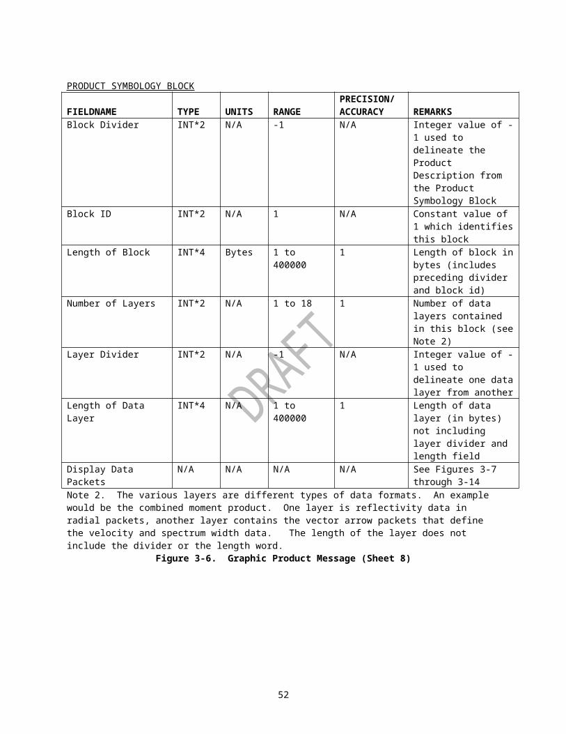
PRODUCT NAME
MSG CODE
HWORD#
CONTENT UNITS RANGE ACCUR/PREC
Snow Depth Missing PeriodsStorm Total Snow Depth
147 30 Use RCA Flag N/A 0 or 1 1
Storm Total Snow Depth
147 47 Maximum Value
Inches 0.0 to 3276.7
0.1, Note 1
Storm Total Snow Depth
147 48 Starting Date Julian Date
1 to 32767 1
Storm Total Snow Depth
147 49 Starting Time Minutes 0 to 1439 1
Storm Total Snow Depth
147 50 Ending Date Julian Date
1 to 32767 1
Storm Total Snow Depth
147 51 Ending Time Minutes 0 to 1439 1
Storm Total Snow Depth
147 52 Azimuth of Max.
Degrees 0 to 359 1
Storm Total Snow Depth
147 53 Range to Max. Nmi 0 to 124 1
Storm Total Snow Water Equivalent
146 27 Length of Missing Periods
Minutes 0 to 32767 1
Storm Total Snow Water Equivalent
146 30 Use RCA Flag N/A 0 or 1 1
Storm Total Snow Water Equivalent
146 47 Maximum Value
Inches 0.00 to 327.67
0.01, Note 1
Storm Total Snow Water Equivalent
146 48 Starting Date Julian Date
1 to 32767 1
Storm Total Snow Water Equivalent
146 49 Starting Time Minutes 0 to 1439 1
Storm Total Snow Water Equivalent
146 50 Ending Date Julian Date
1 to 32767 1
Storm Total Snow Water Equivalent
146 51 Ending Time Minutes 0 to 1439 1
Storm Total Snow Water Equivalent
146 52 Azimuth of Max.
Degrees 0 to 359 1
Storm Total Snow Water Equivalent
146 53 Range to Max. Nmi 0 to 124 1
Storm Track 58 47 Total Number of Storms
N/A 0 to 100 1
SuperOb 136 27 Base Time Minutes 0 to 1439 1SuperOb 136 28 Time Radius Minutes 5 to 90 1SuperOb 136 47 SuperOb Cell
Range SizeKm 1 to 10 1
SuperOb 136 48 SuperOb Cell Azimuth Size
Degrees 2 to 12 1
55

PRODUCT NAME
MSG CODE
HWORD#
CONTENT UNITS RANGE ACCUR/PREC
SuperOb 136 49 Maximum Range
Km 60 to 230 1
SuperOb 136 50 Minimum Number of Samples
N/A 20 to 200 1
SuperOb 136 51 Compression Method
N/A 0 or 1 1
SuperOb 136 52 Uncompressed Product Data Size (MSW)
Bytes 120 - 1409856
1
SuperOb 136 53 Uncompressed Product Data Size (LSW)
1
Super Resolution Digital Base Reflectivity
153 30 Elevation Angle Degree -1.0 to +45.0
.1
Super Resolution Digital Base Reflectivity
153 47 Max Reflectivity
dBZ -32 to +95, (-33)
1, Note 6
Super Resolution Digital Base Reflectivity
153 51 Compression Method
N/A 0 or 1 1
Super Resolution Digital Base Reflectivity
153 52 Uncompressed Product Data Size (MSW)
Bytes 120 to 1329150
1
Super Resolution Digital Base Reflectivity
153 53 Uncompressed Product Data Size (LSW)
Super Resolution Digital Base Velocity
154 30 Elevation Angle Degree -1.0 to +45.0
.1
Super Resolution Digital Base Velocity
154 47 Max Neg. Velocity
Knots -247 to 0 1
Super Resolution Digital Base Velocity
154 48 Max Pos. Velocity
Knots 0 to 245 1
Super Resolution Digital Base Velocity
154 51 Compression Method
N/A 0 or 1 1
Super Resolution Digital Base
154 52 Uncompressed Product Data Size (MSW)
Bytes 120 to 868350
1
56

PRODUCT NAME
MSG CODE
HWORD#
CONTENT UNITS RANGE ACCUR/PREC
VelocitySuper Resolution Digital Base Velocity
154 53 Uncompressed Product Data Size (LSW)
Super Resolution Digital Base Spectrum Width
155 30 Elevation Angle Degree -1.0 to +45.0
.1
Super Resolution Digital Base Spectrum Width
155 47 Max Spectrum Width
Knots 0 to 19 1
Super Resolution Digital Base Spectrum Width
155 51 Compression Method
N/A 0 or 1 1
Super Resolution Digital Base Spectrum Width
155 52 Uncompressed Product Data Size (MSW)
Bytes 120 to 868350
1
Super Resolution Digital Base Spectrum Width
155 53 Uncompressed Product Data Size (LSW)
Surface Rainfall Accum
78 & 79
47 Max Rainfall Inches 0.0 to 189.0
.1, Note 1
Surface Rainfall Accum
78 & 79
48 Mean-field Bias N/A 0.01 to 99.99
.01, Note 1
Surface Rainfall Accum
78 & 79
49 Effective No. G-R Pairs (Sample Size)
N/A 0.00 to 9999.99
.01, Note 1
Surface Rainfall Accum
78 & 79
50 Rainfall End Date
Julian Date
1 to 32767 1
Surface Rainfall Accum
78 & 79
51 Rainfall End Time
Minutes 0 to 1439 1
TVS 61 47 Total Number of TVS
N/A -25 to 25 1, Note 5
TVS 61 48 Total Number of ETVS
N/A -25 to 25 1, Note 5
Tornado Vortex Signature Rapid Update
143 30 Elevation angle degree -1.0 to +45.0
.1
Tornado Vortex Signature Rapid Update
143 47 Total Number of TVS
N/A -25 to 25 1, Note 5
Tornado Vortex 143 48 Total Number N/A -25 to 25 1, Note 5
57

PRODUCT NAME
MSG CODE
HWORD#
CONTENT UNITS RANGE ACCUR/PREC
Signature Rapid Update
of ETVS
Turbulence Detection Algorithm(NTDA)
156, 157
27 Elevation start time in seconds since volume start
Second 0 to 32767 1
Turbulence Detection Algorithm(NTDA)
156, 157
28 Elevation end time in seconds since volume start
Second 0 to 32767 1
Turbulence Detection Algorithm(NTDA)
156, 157
30 Target elevation angle
Degree -1.0 to +45.0
0.1, Note 1
Turbulence Detection Algorithm(NTDA)
156, 157
47 Minimum elevation angle
Degree -1.00 to +45.00
0.01, Note 1
Turbulence Detection Algorithm(NTDA)
156, 157
48 Mean elevation angle
Degree -1.00 to +45.00
0.01, Note 1
Turbulence Detection Algorithm(NTDA)
156, 157
49 Maximum elevation angle
Degree -1.00 to +45.00
0.01, Note 1
User Alert Message
73 -- -- --
User Selectable LayerComposite Reflectivity
137 27 Requested BottomAltitude of Layer
K Feet 0 to 69 1
User Selectable Composite Reflectivity
137 28 Requested TopAltitude of Layer
K Feet 1 to 70 1
User Selectable Layer Composite Reflectivity
137 47 Max Reflectivity
dBZ -32 to 95 1
User Selectable CompositeReflectivity
137 48 Actual bottom Altitude of Layer (adjusted to correct request errors).
K Feet 0 to 69 1
User Selectable Layer Composite
137 49 Actual top Altitude of Layer
K Feet 1 to 70 1
58

PRODUCT NAME
MSG CODE
HWORD#
CONTENT UNITS RANGE ACCUR/PREC
Reflectivity Maximum
(adjusted to correct request errors).
User Selectable Precip.
31 27 End Hour Hours 0 to 23 1
User Selectable Precip.
31 28 Time Span Hours 1 to 24 1
User Selectable Precip.
31 30 Null Product Flag
N/A 0 to 1 1, Note 9
User Selectable Precip.
31 47 Max Rainfall Inches 0.0 to 327.6
.1, Note 1
User Selectable Precip.
31 48 Beg. Date Rainfall
Julian Date
1 to 32767 1
User Selectable Precip.
31 49 Beg. Time Rainfall
Minutes 0 to 1439 1
User Selectable Precip.
31 50 End Date Rainfall
Julian Date
1 to 32767 1
User Selectable Precip.
31 51 End Time Rainfall
Minutes 0 to 1439 1
User Selectable Precip.
31 52 Average Mean-field Bias
N/A 0.01 to 99.99
.01, Note 1
User Selectable Precip.
31 53 Average Effective No. G-R Pairs (Sample Size)
N/A 0.00 to 9999.99
.01, Note 1
User Selectable Snow Depth
151 27 End Hour Hours 0 to 23 1
User Selectable Snow Depth
151 28 Time Span Hours 1 to 30 1
User Selectable Snow Depth
151 30 Use High Scale Flag/Use RCA Flag
N/A 0, 1, 256, or 257
1Note 16
User Selectable Snow Depth
151 47 Maximum Value
Inches 0.00 to 327.67 or 0.0 to 3276.7
0.01 or 0.1, Note 1 and Note 16
User Selectable Snow Depth
151 48 Starting Date Julian Date
1 to 32767 1
User Selectable Snow Depth
151 49 Starting Hour Minutes 0 to 1439 1, Note 22
User Selectable Snow Depth
151 50 Ending Date Julian Date
1 to 32767 1
User Selectable Snow Depth
151 51 Ending Hour Minutes 0 to 1439 1, Note 22
User Selectable Snow Depth
151 52 Azimuth of Max.
Degrees 0 to 359 1
User Selectable Snow Depth
151 53 Range to Max. Nmi 0 to 124 1
User Selectable Snow Water
150 27 End Hour Hours 0 to 23 1
59

PRODUCT NAME
MSG CODE
HWORD#
CONTENT UNITS RANGE ACCUR/PREC
EquivalentUser Selectable Snow Water Equivalent
150 28 Time Span Hours 1 to 30 1
User Selectable Snow Water Equivalent
150 30 Use High Scale Flag/ Use RCA Flag
N/A 0, 1, 256, or 257
1Note 16
User Selectable Snow Water Equivalent
150 47 Maximum Value
Inches 0.000 to 32.767 or 0.00 to 327.67
0.001 or 0.01, Note 1 and Note 16
User Selectable Snow Water Equivalent
150 48 Starting Date Julian Date
1 to 32767 1
User Selectable Snow Water Equivalent
150 49 Starting Hour Minutes 0 to 1439 1, Note 22
User Selectable Snow Water Equivalent
150 50 Ending Date Julian Date
1 to 32767 1
User Selectable Snow Water Equivalent
150 51 Ending Hour Minutes 0 to 1439 1, Note 22
User Selectable Snow Water Equivalent
150 52 Azimuth of Max.
Degrees 0 to 359 1
User Selectable Snow Water Equivalent
150 53 Range to Max. Nmi 0 to 124 1
VAD Wind Profile
48 47 Max Speed (Horiz)
Knots 0 to 350 1, Note 5
VAD Wind Profile
48 48 Direct of Max Speed
Degree 0 to 359 1, Note 1 & 5
VAD Wind Profile
48 49 Alt of Max Speed
Feet/10 00.00 to 70.00
.01, Note 5
Velocity Az. Display
84 47 Wind Speed (Horiz)
Knots 0 to 350 1, Note 5
Velocity Az. Display
84 48 Wind Direct(Horiz)
Degree 0 to 359 1, Note 1 & 5
Velocity Az. Display
84 30 Wind Alt (Horiz)
1000 Feet
0 to 70 1
Velocity Az. Display
84 49 Elevation Angle Degree -1.0 to +45.0
.1, Note 1 & 5
Velocity Az. Display
84 50 Slant Range Nmi 0.0 to 124.0
.1, Note 1 & 5
Velocity Az. Display
84 51 RMS Error Knots 0 to 29 1, Note 5
Vertically Integ. Liq
57 47 Max VIL Kg/Sq. meter
0 to 200 1
Differential 158,15 30 Elevation Angle Degree -1.0 to .1, Note 1
60

PRODUCT NAME
MSG CODE
HWORD#
CONTENT UNITS RANGE ACCUR/PREC
Reflectivity 9 +45.0 Differential Reflectivity
158,159
47 Minimum Differential Reflectivity
dB -7.9 to +7.9 .1
Differential Reflectivity
158,159
48 Maximum Differential Reflectivity
dB -7.9 to +7.9 .1
Correlation Coefficient
160,161
30 Elevation Angle Degree -1.0 to +45.0
.1, Note 1
Correlation Coefficient
160,161
47 Minimum Correlation Coefficient
N/A 0.2 to 1.05 .00333
Correlation Coefficient
160,161
48 Maximum Correlation Coefficient
N/A 0.2 to 1.05 .00333
Specific Differential Phase
162,163
30 Elevation Angle Degree -1.0 to +45.0
.1, Note 1
Specific Differential Phase
162,163
47 Minimum Specific Differential Phase
Deg/km -2.0 to +10.6
.05
Specific Differential Phase
162,163
48 Maximum Specific Differential Phase
Deg/km -2.0 to +10.6
.05
Hydrometeor Classification
164,165
30 Elevation Angle Degree -1.0 to +45.0
.1, Note 1
Hydrometeor Classification
164 47 Mode Filter Size
N/A 1 to 15 1
Melting Layer 166 30 Elevation Angle Degree -1.0 to +45.0
.1, Note 1
One Hour Accum
169 30 Null Product Flag
N/A 0 or 1 1, Note 9, Note 19
One Hour Accum
169 47 Max Accum Inches 0.0 to 100.0
.1, Note 1
One Hour Accum
169 48 Ending Date of Accumulation
Julian Date
1 to 32767 1
One Hour Accum
169 49 Ending Time of Accumulation
Minutes 0 to 1439 1
One Hour Accum
169 50 Mean-field Bias N/A 0.01 to 99.99
.01, Note 1, Note 18
One Hour Accum
169 51 Sample Size (Effective No. Gage/Radar Pairs)
N/A 0.00 to 9999.99
.01, Note 1, Note 18
One Hour Accum
169 54 Product Version Number
N/A 1 to 32767 1
Digital Accum Array
170 30 Null Product Flag
N/A 0 or 1 1, Note 9, Note 19
Digital Accum 170 47 Max Accum Inches 0.0 to .1, Note 1
61

PRODUCT NAME
MSG CODE
HWORD#
CONTENT UNITS RANGE ACCUR/PREC
Array 100.0 Digital Accum Array
170 48 Ending Date of Accumulation
Julian Date
1 to 32767 1
Digital Accum Array
170 49 Ending Time of Accumulation
Minutes 0 to 1439 1
Digital Accum Array
170 50 Mean-field Bias N/A 0.01 to 99.99
.01, Note 1, Note 18
Digital Accum Array
170 54 Product Version Number
N/A 1 to 32767 1
Storm Total Accum
171 27 Start Date of Accumulation
Julian Date
1 to 32767 1
Storm Total Accum
171 28 Start Time of Accumulation
Minutes 0 to 1439 1
Storm Total Accum
171 30 Null Product Flag
N/A 0 or 1 1, Note 9, Note 19
Storm Total Accum
171 47 Max Accum Inches 0.0 to 100.0
.1, Note 1
Storm Total Accum
171 48 Ending Date of Accumulation
Julian Date
1 to 32767 1
Storm Total Accum
171 49 Ending Time of Accumulation
Minutes 0 to 1439 1
Storm Total Accum
171 50 Mean-field Bias N/A 0.01 to 99.99
.01, Note 1, Note 18
Storm Total Accum
171 51 Sample Size (Effective No. Gage/Radar Pairs)
N/A 0.00 to 9999.99
.01, Note 1, Note 18
Storm Total Accum
171 54 Product Version Number
N/A 1 to 32767 1
Digital Storm Total Accum
172 27 Start Date of Accumulation
Julian Date
1 to 32767 1
Digital Storm Total Accum
172 28 Start Time of Accumulation
Minutes 0 to 1439 1
Digital Storm Total Accum
172 30 Null Product Flag
N/A 0 or 1 1, Note 9, Note 19
Digital Storm Total Accum
172 47 Max Accum Inches 0 to 100.00 .1
Digital Storm Total Accum
172 48 Ending Date of Accumulation
Julian Date
1 to 32767 1
Digital Storm Total Accum
172 49 Ending Time of Accumulation
Minutes 0 to 1439 1
Digital Storm Total Accum
172 50 Mean-field Bias N/A 0.0 to 99.99
.01, Note 1, Note 18
Digital Storm Total Accum
172 54 Product Version Number
N/A 1 to 32767 1
Digital User Selectable Accum
173 27 End Time Minutes 0 to 1439 1
Digital User 173 28 Time Span Minutes 15 to 1440 1
62

PRODUCT NAME
MSG CODE
HWORD#
CONTENT UNITS RANGE ACCUR/PREC
Selectable Accum
Minutes
Digital User Selectable Accum
173 30 Missing Period Flag (high byte) & Null Product Flag (low byte)
N/A 0 or 1 in either or both of the bytes
1, Note 9, Note 19, Note 21
Digital User Selectable Accum
173 47 Max Accum Inches 0.0 to 327.6
.1, Note 1
Digital User Selectable Accum
173 48 End Date Julian Date
1 to 32767 1
Digital User Selectable Accum
173 49 Start Time Minutes 0 to 1440 1
Digital User Selectable Accum
173 50 Mean-field Bias N/A 0.01 to 99.99
.01, Note 1, Note 18
Digital User Selectable Accum
173 54 Product Version Number
N/A 1 to 32767 1
Digital One-Hour Difference
174 47 Max Accum Difference
Inches -100.0 to 100.0
.1, Note 1
Digital One-Hour Difference
174 48 Ending Date of Accumulation
Julian Date
1 to 32767 1
Digital One-Hour Difference
174 49 Ending Time of Accumulation
Minutes 0 to 1439 1
Digital One-Hour Difference
174 50 Min Accum Difference
Inches -100.0 to 100.0
.1, Note 1
Digital One-Hour Difference
174 54 Product Version Number
N/A 1 to 32767 1
Digital Storm Total Difference
175 27 Start Date of Accumulation
Julian Date
1 to 32767 1
Digital Storm Total Difference
175 28 Start Time of Accumulation
Minutes 0 to 1439 1
Digital Storm Total Difference
175 30 Null Product Flag
N/A 0 or 1 1, Note 9, Note 19
Digital Storm Total Difference
175 47 Max Accum Difference
Inches -100.0 to 100.0
.1, Note 1
Digital Storm Total
175 48 Ending Date of Accumulation
Julian date
1 to 32767 1
63

PRODUCT NAME
MSG CODE
HWORD#
CONTENT UNITS RANGE ACCUR/PREC
Difference Digital Storm Total Difference
175 49 Ending Time of Accumulation
Minutes 0 to 1439 1
Digital Storm Total Difference
175 50 Min Accum Difference
Inches -100.0 to 100.0
.1, Note 1
Digital Storm Total Difference
175 54 Product Version Number
N/A 1 to 32767 1
Digital Instantaneous Precipitation Rate
176 27 Hybrid Rate Scan Date
Julian date
1 to 32767 1
Digital Instantaneous Precipitation Rate
176 28 Hybrid Rate Scan Time
Minutes 0 to 1439 1
Digital Instantaneous Precipitation Rate
176 30 Precipitation Detected Flag (high byte) & Gage Bias to be Applied Flag (low byte)
N/A 0 or 1 N/A, Note 18
Digital Instantaneous Precipitation Rate
176 47 Maximum Instantaneous Precipitation Rate
in/hr 0 to 65535 1, Note 1, Note 20
Digital Instantaneous Precipitation Rate
176 48 Hybrid Rate Percent Bins Filled
Percent 0.01 - 100.00
.01%, Note 1
Digital Instantaneous Precipitation Rate
176 49 Highest Elev. Used
Degrees 0.5 - 19.5 0.1°, Note 1
Digital Instantaneous Precipitation Rate
176 50 Mean-field Bias N/A 0.01 to 99.99
.01, Note 1, Note 18
Digital Instantaneous Precipitation Rate
176 54 Product Version Number
N/A 1 to 32767 1
Hybrid Hydrometeor Classification
177 47 Mode Filter Size
N/A 1 to 15 1
Hybrid Hydrometeor
177 48 Hybrid Rate Percent Bins
Percent 0.01 - 100.00
.01%, Note 1
64

PRODUCT NAME
MSG CODE
HWORD#
CONTENT UNITS RANGE ACCUR/PREC
Classification FilledHybrid Hydrometeor Classification
177 49 Highest Elev. Used
Degrees 0.5 - 19.5 0.1°, Note 1
Hybrid Hydrometeor Classification
177 54 Product Version Number
N/A 1 to 32767 1
Note 1. Scaled Integer, precision column defines scaling.Note 2. Real*4 represents one fullword (32 bits) of real data, where the values are in IEEE-754-1985 floating point representation.Note 3. Corresponds to MSB of bit map as defined in Table II- A.Note 4. Corresponds to LSB of bit map as defined in Table II- A.
65

Note 5. Msg Code Halfword DescriptionEcho Tops Product
41 47 Value of zero altitude indicates "No Echos Detected
PUP Text Message
77 49 User designation is set by the RPGOP only, where: 0 = Send message to all dedicated users; >0 = Send message to the user on specific line identified.
Layer Products 63-67,89-90
48 Value of zero layer bottom indicates "Surface"
VAD Wind Profile
48 49 Altitude value of -9999 indicates ("Wind Barbs") non-valid altitude, speed and direction which are displayed as blanks
Velocity Azimuth
84 47 Wind speed value of -9999 Display indicates non-valid speed and direction. Speed and direction are displayed as blanks
50 Slant range value of -9999 indicates non-valid slant range and elevation angle. Values of slant range and elevation angle are displayed as blanks
51 RMS value of -9999 indicates non-valid RMS. Value of RMS is displayed as blanks.
TVS 61 47 A negative value indicates that the Total Number of TVSs identified by the algorithm exceeded the Maximum number of TVSs in adaptation data. Those with the higher Low-level Delta Velocity were retained.
TVS 61 48 A negative value indicates that the Total Number of ETVSs identified by the algorithm exceeded the Maximum number of ETVSs in adaptation data. Those with the higher Low-level Delta Velocity were retained.
Storm Mean Radial Velocity
55-56 47 A maximum negative velocity of -999 indicates a non-valid maximum negative velocity. Values are displayed as asterisks.
48 A maximum positive velocity of -777 indicates a non-valid maximum positive velocity. Values are displayed as asterisks.
Note 6. Value enclosed in parentheses of range column is a code to indicate data is unavailable.Note 7. Applicable only to products generated as a result of an Alert.Note 8. This halfword defines the clutter map channel type (Version 0 only) and segment number (Version 0 and Version 1). For Version 0, bit 15 (LSB) defines the channel type. If bit 15 is 0, then it is a clutter filter control product for the surveillance channel. If bit 15 is 1, then it is the Doppler channel clutter filter control product. For both Version 0 and Version 1, bits 14 through 10 specify elevation segment numbers 1 through 5, respectively. Segment 1 is the lowest elevation clutter filter map, segment 5 is the upper elevation clutter filter map.Note 9. If flag is set, the product is null i.e., rainfall data to build product was unavailable.
66

Note 11. Velocity Precision Code indicates the quantization of the base velocity data used to create this product. A value of 1 denotes 0.5 m/s and 2 denotes 1.0 m/s. Regardless of the value of this code, product 93 is formatted as if the precision is always 0.5 m/s.Note 12. The value entered for the upper limit of the Digital Storm Total ( DSP) Max Rainfall value is a theoretical limit; the actual upper limit has no bound, as the DSP data values are adjusted ( scaled ) to fit within the range ( 0 - 255), based upon the Max Rainfall value. The Accuracy/Precision increases according to the scaling ( i.e., .01, .02, etc. ) and also has no, actual upper limit.Note 13: The Legacy RDA system created the "Notchwidth Map". The Open RDA system uses a different clutter filtering scheme that makes the "Notchwidth" terminology obsolete. The Open RDA system calls this map the "Clutter Filter Map".Note 14. Applies to Legacy RDA systems only.Note 15. Applies to Open RDA systems only.Note 16. Two flags are stored in this halfword. The high byte contains the High Scale Flag; the low byte contains the Use RCA flag. Counting bit 0 as the most significant bit, the High Scale Flag is in bit 7 and the Use RCA flag is in bit 15. If the High Scale Flag is set, the maximum value in halfword 47 for the User Selectable Snow Water Equivalent (msg code 150) must be divided by 100 and User Selectable Snow Depth (msg code 151) must be divided by 10. If the High Scale Flag is not set, the maximum value in halfword 47 is divided by 1000 and 100 for the User Selectable Water Equivalent and the User Selectable Snow Depth, respectively. Note 17. A value of 0 indicates the Clutter Bypass Map used for the product was generated by the Radar System Test off-line software. A value of 1 indicates the Clutter Bypass Map used for the product was generated by the Clutter Mitigation Decision (CMD) algorithm.Note 18. Gage bias is not being implemented for dual-polarization QPE products at this time. However, gage bias and its associated adaptable parameters will be implemented in the future. These parameters are used as placeholders.Note 19. If the null product flag is non-zero, this means there are no accumulations present in the product for the reasons given below. This will also be indicated textually in the Product Symbology Block.
1: “No accumulation available. Threshold: ‘Elapsed Time to Restart’ [TIMRS] xx minutes exceeded.”
2: “No precipitation detected during the specified time span.” 3: “No accumulation data available for the specified time span.”4: “No precipitation detected since hh:mmZ. Threshold: 'Time Without Precipitation
for Resetting Storm Totals’ [RAINT] is xx minutes” or “No precipitation detected since RPG startup.”
5: “No precipitation detected since hh:mmZ” or “No precipitation detected since RPG startup.”Note 20. Halfword 47 of Digital Instantaneous Precipitation Rate contains the Maximum Rainfall Rate in thousandths of an inch, with values ranging from 0 to 65535, and should be treated like an unsigned short integer data type.Note 21. In the Digital User Selectable Accum product only, the Null Product Flag is stored in the least significant byte of the halfword. The Missing Period Flag will be stored in the most significant byte of the halfword. Note 22. Until enough hours have elapsed to generate the User Selectable Snow Water Equivalent and Snow Depth products, the minutes will be rounded to the nearest starting and ending hours requested by the user. After the products can be generated, the starting and ending hours will reflect the actual times used to generate the products. These times may deviate from the whole hour by as much as half the volume scan interval.
67

Table VI. Product Dependent Definition for Product Symbology Block
PRODUCT NAME
CONTENT UNITS RANGE ACCURACY / PRECISION
REMARKS
VAD WIND PROFILE
Altitude Kft 1 to 70 1
Volume Scan StartTime
N/A Hours: 00 to 23Minutes: 00 to 59
1
VELOCITY AZIMUTHDISPLAY
Velocity Kts +/-200, +/-100,+/-80, +/-60, +/-40
1
Azimuth Degrees 1 to 360 1Best Fit Function inthe form
A1+ VSIN(AZ + )Where:A = Harmonic Coefficient (Fourier #1) V = SQRT[CF22+CF32}
with CF2 and CF3 corresponding to Harmonic Coefficient (Fourier #2 & #3) & = - Horizontal Wind Direction - 90°
Kts
Kts
Degrees
-39 to 39
0 to +247
0 to 359
1
1
1
REFLECTIVITY CROSS SECTION
Azimuth Degrees 0 to 359 1
Range nmi 0 to 124 1
Max Reflectivity
dBZ -32 to 95(-999)*
1 () *Value Indicates Data Not
68

PRODUCT NAME
CONTENT UNITS RANGE ACCURACY / PRECISION
REMARKS
AvailableHeight of Max Reflectivity
Kft 0 to 70 (71)* 1 () *Value Indicates Data Not Available
Max ReflectivityPosition:· Azimuth· Range
Degrees nmi
0 to 359 0 to 124
1 1
VELOCITY CROSSSECTION
Azimuth Degrees 0 to 359 1
Range nmi 0 to 124 1Max Velocity Kts 0 to 245 1Height of MaxVelocity
Kft 0 to 70 (71)* 1 ( ) * Value Indicatesdata not available
Max Velocity Position:· Azimuth· Range
Degrees nmi
0 to 359 0 to 124
1 1
Min Velocity Kts -247 to 0 1Height of Min Velocity
Kft 0 to 70 (71)* () *Value Indicates Data Not Available
Min Velocity Position:
Azimuth Range
Degrees nmi
0 to 359 0 to 124
1 1
USER SELECTABLE PRECIPITATION
Status Alphanumeric - Product Not Generated: Unable To Read
N/A Status messages will be sent only if error
69

PRODUCT NAME
CONTENT UNITS RANGE ACCURACY / PRECISION
REMARKS
Data from Database- Product Not Generated: Illegal Times in Product Request- Product Not Generated: Insufficient Accumulation Date In Hourly Database- Hours Available for Request
conditions occur
ONE-HOUR SNOW WATER EQUIVALENT AND ONE-HOUR SNOW DEPTH
Status Alphanumeric - Data not available because: No buffer space for product- Data not available because: Product too big for existing buffer- Data not available because: Insufficient data for hourly accumulations
N/A Status messages will be sent only if error conditions occur
STORM TOTAL SNOW WATER EQUIVALENT AND STORM TOTAL SNOW DEPTH
Status Alphanumeric - Data not available because: First volume of accumulations
N/A Status messages will be sent only if error conditions occur
70

PRODUCT NAME
CONTENT UNITS RANGE ACCURACY / PRECISION
REMARKS
- Data not available because: No buffer space for product- Data not available because: Product too big for existing buffer- Data not available because: First volume scan of accumulations
USER SELECTABLE SNOW WATER EQUIVALENT AND USER SELECTABLE SNOW DEPTH
Status Alphanumeric - Data not available because: No buffer space for product- Data not available because: Product too big for existing buffer- Data not available because: Insufficient number of hourly accumulations- Data not available because: Current hour is not the requested end hour
N/A Status messages will be sent only if error conditions occur
Digital User -Selectable Accumulation
Status Alphanumeric - No precipitation detected during the specified time span
N/A Status messages will be sent only if error conditions occur
71

PRODUCT NAME
CONTENT UNITS RANGE ACCURACY / PRECISION
REMARKS
- No accumulation data available for the specified time span
Storm-Total Accumulation
Status Alphanumeric - No precipitation detected since dd/mm/yy hh:mm Z. Threshold: 'Time Without Precipitation for Resetting Storm Totals'" " [RAINT] is mm minutes
- No precipitation detected since RPG startup. Threshold: 'Time Without Precipitation for Resetting Storm Totals'" " [RAINT] is mm minutes
N/A Status messages will be sent only if error conditions occur
Digital Storm-Total Accumulation
Status Alphanumeric - No precipitation detected since dd/mm/yy hh:mm Z. Threshold: 'Time Without Precipitation for Resetting Storm Totals'" " [RAINT] is
N/A Status messages will be sent only if error conditions occur
72

PRODUCT NAME
CONTENT UNITS RANGE ACCURACY / PRECISION
REMARKS
mm minutes
- No precipitation detected since RPG startup. Threshold: 'Time Without Precipitation for Resetting Storm Totals'" " [RAINT] is mm minutes
Digital Storm-Total Difference
Status Alphanumeric - No precipitation detected since dd/mm/yy hh:mm Z. Threshold: 'Time Without Precipitation for Resetting Storm Totals'" " [RAINT] is mm minutes
- No precipitation detected since RPG startup. Threshold: 'Time Without Precipitation for Resetting Storm Totals'" " [RAINT] is mm minutes
N/A Status messages will be sent only if error conditions occur
One-Hour Accumulation
Status Alphanumeric - No precipitation detected since dd/mm/yy hh:mm Z.
- No precipitation detected since RPG startup.
N/A Status messages will be sent only if error conditions occur
Digital Status Alphanumeric - No N/A Status
73
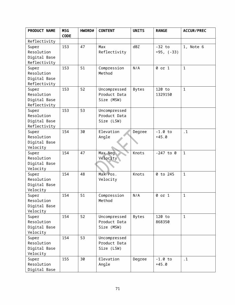
PRODUCT NAME
CONTENT UNITS RANGE ACCURACY / PRECISION
REMARKS
Accumulation Array
precipitation detected since dd/mm/yy hh:mm Z.
- No precipitation detected since RPG startup.
messages will be sent only if error conditions occur
All Dual-Polarization Accumulation Products
Status Alphanumeric - No accumulation available.Threshold: 'Elapsed Time to Restart' [TIMRS] (mm minutes) exceeded
N/A Status messages will be sent only if error conditions occur
All Dual-Polarization Accumulation Products
Status Alphanumeric - Product unavailable - unknown reason nn
N/A “Default” status messages will be sent only if error conditions occur and if error condition is unknown
74

Table VII. Product Dependent Definition for Graphic Alphanumeric Block
PRODUCT NAME CONTENT UNITS RANGE ACCURACY/PRECISION
REMARKS
COMPOSITEREFLECTIVITY OR COMPOSITE REFLECTIVITY EDITED FOR AP
Storm Cell ID Alphanumeric
A0 through Z0,then A1 through Z1, then A2...Z9.
N/A The sequence isrecycled following Note 1
Storm Position: · Azimuth · Range
Degrees nmi
0 to 360 0 to 248
1 1
Note 1
Maximum Reflectivity
dBZ 0 to 95 1 Note 1
Height of MaximumReflectivity
Kft 0.0 to 70.0 0.1 Note 1
Cell-Based VIL kg/m2 0 to 120 1 Note 1Storm Top Kft 0.00 to
70.000.1 If the storm top
was identified at the highest elevation, the value is qualified with ">", Note 1
Forecast Movement
· Storm Direction · Storm Speed
Alphanumeric or Degrees Kts
New or
0 to 360 0 to 999
1 1
Newly identified storm cells are labeled "NEW". Note 1
MDAStrength Rank
Alphanumeric
NONE, 1 to 25
1
TVS Feature Type
Alphanumeric
NONE, TVS or ETVS
N/A If both a TVS and ETVS are associated with the same storm cell, then "TVS" will be displayed. Note 1
Hail Alphanum UNKNOWN If the maximum
75

PRODUCT NAME CONTENT UNITS RANGE ACCURACY/PRECISION
REMARKS
Characteristics· Probability of Hail (POH)· Probability of Severe Hail (POSH)· Maximum Expected Hail Size
eric or Percent
Percent
Inches
or
0 to 100
0 to 100
0.00 and 0.50 to 4.00
10
10
0.25
expected hail size exceeds 4.0 inches, the hail size is labeled ">4.00".
If the Probability of Hail and the Probability of Severe Hail are greater the 0% and the maximum expected hail size is less than 0.50 inches, the hail size is labeled "<0.50".
If the Hail Characteristics cannot be determined, the Hail Characteristics are labeled "UNKNOWN".Note 1
ECHO TOPS Status Alphanumeric
No Echoes Detected
N/A This status message will be sent only if the Echo Tops Grid is all zeroes.
HAIL INDEX Storm Cell ID Alphanumeric
A0 through Z0, then A1 through Z1, then A2...Z9
N/A The sequence is recycled following Z9, (See Note 1)
Storm Position Azimuth Range
Degrees Nmi
0 to 360 0 to 248
1 1
Note 1
Hail Characteristics:
-Probability of Hail (POH)
Alphanumeric or Percent
UNKNOWN or 0 to 100
10
If maximum expected hail size exceeds 4.0 inches, the hail size is labeled ">4.00".
76

PRODUCT NAME CONTENT UNITS RANGE ACCURACY/PRECISION
REMARKS
-Probability of Severe Hail (POSH)
Percent 0 to 100 10 If the Probability of Severe hail is greater than 0% and the maximum expected hail size is less than 0.50 inches, the hail size is labeled "<0.50".
-Maximum Expected Hail Size
Inches 0.00 and 0.50 to 4.00
0.25 If the Hail Characteristics cannot be determined, the Hail Characteristics are labeled "UNKNOWN"Note 1
Hail Temperature Altitudes(MSL) 0 Degree Celsius
Kft 0.0 to 70.0 .1 Note 1
-20 Degree Celsius
Kft 0.0 to 70.0 .1
Time of last change to Hail Temperature Altitude
N/AHours: 00 to 23Minutes: 00 to 59
N/A Note 1
Date of last change to Hail Temperature Altitudes
N/A Months: 01 to 12Days: 01 to 31Years: 00 to 99
N/A Note 1
STORM TRACKING INFORMATION
Storm Cell ID Alphanumeric
A0 through Z0, then A1 through Z1, then A2....Z9
N/A The sequence is recycled following Z9.Note 1
Storm Position · Azimuth · Range
Degrees nmi
0 to 3600 to 248
11
Note 1
Forecast Movement · Direction · Speed
Alphanumeric or DegreesKts
NEW or 0 to 3600.0 to 999
10.1
Newly identified storm cells are labeled "NEW"Note 1
77

PRODUCT NAME CONTENT UNITS RANGE ACCURACY/PRECISION
REMARKS
Forecast Error · Error · Mean
nminmi
0.0 to 99.90.0 to 99.9
0.10.1
Note 1
Maximum Reflectivity
dBZ 0 to 95 1 Note 1
Height of Maximum Reflectivity
Kft 0.0 to 70.0 0.1 Note 1
MESOCYCLONE Storm Cell ID Alphanumeric
A0 through Z0, then A1 through Z1, then A2 through Z9
N/A The sequence is recycled following Z9Note 1
Vortex Type Alphanumeric
3D Correlated Shear (3 DC SHR), Mesocyclone (MESO)
N/A
Mesocyclone Position: · Azimuth · Range
Degrees nmi
0 to 360 0 to 124
1 1
Mesocyclone BaseValue
Kft 0.0 to 33.1 0.1
Mesocyclone Top Value
Kft 0.0 to 33.1 0.1
Diameter (Radial)
nmi 0.0 to 99.9 0.1
Diameter (Azimuthal)
nmi 0.0 to 99.9 0.1
MESOCYCLONERAPID UPDATE
Storm Cell ID Alphanumeric
A0 through Z0, then A1 through Z1, then A2 through Z9
N/A The sequence is recycled following Z9Note 1
78

PRODUCT NAME CONTENT UNITS RANGE ACCURACY/PRECISION
REMARKS
Feature Status Alphanumeric
New (NEW), Extrapolated (EXT),Persistent (PER),Increasing (INC)
N/A NEW: Feature new this volume scan; EXT: Feature from previous scan with extrapolated position; PER: found in both previous and current volume; INC: Like PER but with increasing shear and/or Vortex Type.
Vortex Type Alphanumeric
3D Correlated Shear (3 DC SHR), Mesocyclone (MESO)
N/A "^" displayed when Vortex Type from current volume
Mesocyclone Position: Azimuth Range
Degrees nmi
0 to 3600 to 124
1 1
"^" displayed when position from current volume
Mesocyclone BaseValue
Kft 0.0 to 33.1 0.1 "^" displayed when Base or Top from current volume
Mesocyclone Top Value
Kft 0.0 to 33.1 0.1 "^" displayed when Base or Top from current volume
Diameter (Radial)
nmi 0.0 to 99.9 0.1 "^" displayed when Diameter from current volume
Diameter (Azimuthal)
nmi 0.0 to 99.9 0.1 "^" displayed when Diameter from current volume
MESOCYCLONE DETECTION
Circulation ID N/A 0 through 999
N/A The sequence is recycled following 999. Note 2
79

PRODUCT NAME CONTENT UNITS RANGE ACCURACY/PRECISION
REMARKS
Associated SCIT Storm ID
N/A A0 through Z0,then A1 through Z1, then A2...Z9
N/A Closest SCIT identified storm cell ID.
Strength Rank N/A 1 to 25 1 If the strength rank was computed by the Low-Top or Shallow method, an L or S will also be displayed.
Low Level (base) Rotational Velocity
Kts 0 to 129 1
Position: Azimuth Range
Degrees nmi
0 to 360 0 to 124
1 Base 2D feature component
Height of Maximum Rotational Velocity(ARL)
Kft 0 to 33 1
Maximum Rotational Velocity
Kts 0 to 129 1
Base Height(ARL)
Kft 0 to 33 1 If the Base is on the lowest elevation scan or below 1km, then the height is preceded by a "<" in the display.
Depth Kft 0 to 33 1 If the Base is on the lowest elevation scan or below 1km, then the Depth is preceded by a ">" in the display.
TORNADO VORTEX SIGNATURE (TVS)
Feature Type Alphanumeric
TVS or ETVS
N/A
Storm Cell ID Alphanum A0 N/A The sequence is
80

PRODUCT NAME CONTENT UNITS RANGE ACCURACY/PRECISION
REMARKS
eric through Z0,then A1 through Z1. then A2...Z9."??" is displayed if the TVS feature is not associated with a storm cell.
recycled following Z9
TVS Feature Position: · Azimuth · Range
Degrees nmi
0 to 359 0 to 124
1 1
Average Delta Velocity
kts 0 to 494 1
Low-level Delta Velocity
kts 0 to 494 1
Maximum Delta Velocity
kts 0 to 494 1
Base kft 0.0 to 70.0 0.01 If the Base is on the lowest elevation scan, then it is preceded by a "<" in the display.
Depth kft 0 to 70 1 If the base or top is on the lowest or highest elevation scan, then the Depth is preceded by a "<" or ">" in the display, respectively
TORNADO VORTEX SIGNATURE RAPID UPDATE
Feature Type Alphanumeric
TVS or ETVS
N/A See Note 1
Storm Cell ID Alphanumeric
A0 through
N/A The sequence is recycled
81

PRODUCT NAME CONTENT UNITS RANGE ACCURACY/PRECISION
REMARKS
Z0, then A1 through Z1, then A2,…, Z9, or ?? is displayed if the TVS feature is not associated with a storm cell.
following Z9Note 1
Feature Status Alphanumeric
New (NEW),Extrapolated (EXT),Persistent (PER),Increasing (INC)
N/A NEW: Feature is new in this volume scan;EXT: Feature from previous volume scan with extrapolated position;PER: Feature found in both previous and current volume scan;INC:Like PER but with increasing in either LLDV, feature type, or depth.
Feature Position:• Azimuth• Range
Degree nmi
0 to 360 0 to 124
1 1
See Note 1
Average Delta Velocity
kts 0 to 494 1 See Note 1
Low Level (base) Delta Velocity
kts 0 to 494 1 See Note 1
Maximum Delta Velocity
kts 0 to 494 1 See Note 1
Base Height kft 0.0 to 70.0 0.01 If the Base is on the lowest elevation scan, then it is preceded by a "<" in the display.
See Note 1Depth kft 0 to 70 1 If the base or top
is on the lowest or highest
82

PRODUCT NAME CONTENT UNITS RANGE ACCURACY/PRECISION
REMARKS
elevation scan, then the Depth is preceded by a "<" or ">" in the display, respectively.
See Note 1USER SELECTABLE PRECIPITATION
Gage Bias Flag N/A Applied/Not Applied
N/A
Number of Hours in Product
N/A 1 to 24 0/1
End Times Hours 00 to 23 0/1Bias Estimate N/A 0.00 to
99.990.01
Hour Included Flag
N/A Yes or No N/A
Note 1: “^” displayed when the attribute(s) is (are) updated to the current detectionNote 2: When no mesocyclones are detected this negative condition will be indicated by the absence of this data block from the product.
83
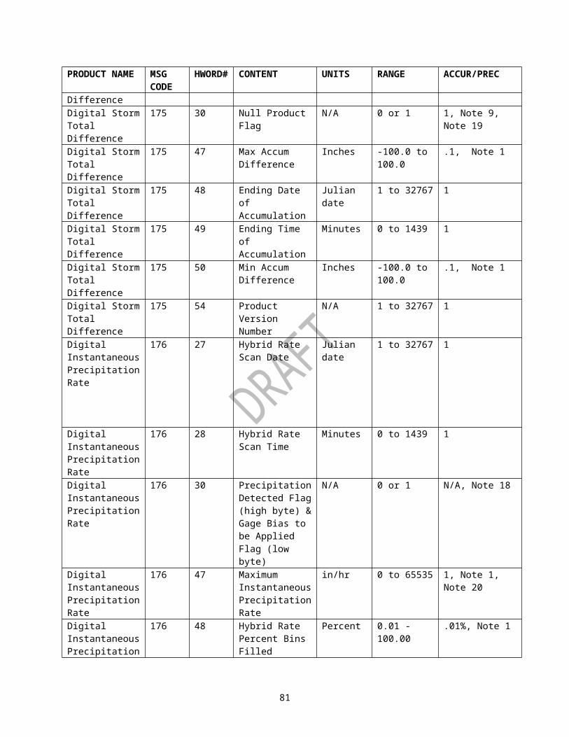
Table VIII. Product Dependent Definition for Tabular Alphanumeric Block
PRODUCT NAME CONTENT UNITS RANGE ACCURACY/PRECISION
REMARKS
VAD WIND PROFILE
Site Adaptable Parameters
See Remarks
See Remarks
See Remarks
2820003 Pt1, Table A-16 VAD
ALT 100ft 0 to 700 1U m/s -127.0 to
126.00.1
V m/s -127.0 to 126.0
0.1
W cm/s -999.9 to 9999.9
0.1
DIR degrees 0 to 360 1SPD knots 0 to 999 1RMS knots 0 to 30.0 0.1DIV 10/s -99.9999
to 999.9999
0.0001
SRNG nm 0.0 to 124.00
0.01
ELEV degrees -1.0 to 45.0
0.1
STORM TRACKINGINFORMATION
Radar ID N/A 0 to 999 1
Volume Scan StartDate
N/A Months: 1 to 12Days: 1 to 31Years: 0 to 99
N/A
Volume Scan StartTime
N/A Hours: 0 to 23Minutes: 0 to 59Seconds: 0 to 59
N/A
Number of Storm Cells
N/A 0 to 100 1
Average Storm Cell Motion· Speed kts 0 to 99 1
Only on first page of Alphanumeric Product
Direction degrees 0 to 360 1
Storm Cell ID Alphanumeric
A0 through Z0,then A1 through
N/A The sequence isrecycled following Z9 Note 1
84
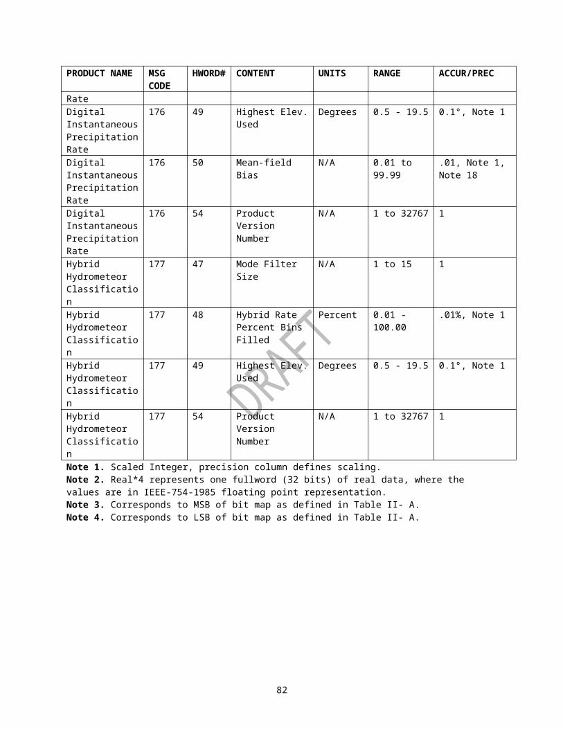
PRODUCT NAME CONTENT UNITS RANGE ACCURACY/PRECISION
REMARKS
Z1, then A2....Z9
Current Position: · Azimuth Degrees 0 to 360 1 Note 1· Range nmi 0 to 24 1Forecast Movement· Direction
Alphanumeric or Degrees
0 to 359 1 Note 1
Speed Kts 0 to 999 1Forecast Error nmi 0.0 to
99.00.1 Note 1
Mean Forecast Error
nmi 0.0 to 99.0
0.1 Note 1
The Azimuth and Range Position for each forecast interval up to four forecast intervals
Alphanumeric or Degree Nmi
NO DATA or0 to 3600 to 248
1 Note 1
Site Store Cell Tracking/Forecast Position Adaptable Parameters
See Remarks
See Remarks
See Remarks
2820003, Pt1, Table A-6 Storm Cell Tracking
MESOCYCLONE Radar ID N/A 0 to 999 1Volume Scan Start Date
N/A Months: 1 to 12Days: 1 to 31Years: 0 to 99
N/A
Volume Scan Start Time
N/A Hours: 0 to 23Minutes: 0 to 59Seconds: 0 to 59
N/A
Number of Storm Cells
N/A 0 to 100 1
Feature ID Alphanumeric
0 through 20
1
Storm Cell ID Alphanumeric
A0 through Z0, then A1 through Z1, then A2....Z9
N/A The sequence is recycled followed Z9
Feature Type Alphanumeric
Uncorrelated Shear
N/A
85

PRODUCT NAME CONTENT UNITS RANGE ACCURACY/PRECISION
REMARKS
(UNC SHR), 3D Correlated Shear (3DC SHR), Mesocyclone (MESO)
Mesocyclone Position:· Azimuth
Degrees 0 to 360 1
Range nmi 0 to 124 1Mesocyclone Height
Kft 0.0 to 33.1
0.1
Mesocyclone Base Value
Kft 0.0 to 33.1
0.1
Mesocyclone Top Value
Kft 0.0 to 33.1
0.1
Diameter (Radial) nmi 0 to 124 0.1Diameter (Azimuthal)
nmi 0 to 780 0.1
Maximum Shear (tangential)
E-3/sec 0 to 999 1
Site Adaptable Parameters
See Remarks
See Remarks
See Remarks
2820003, Pt1, Table A-17 Mesocyclone Detection
TORNADO VORTEX SIGNATURE (TVS)
Radar ID N/A 0 to 999 1
Volume Scan Start Date
N/A Months: 1 to 12Days: 1 to 31Years: 0 to 99
N/A
Volume Scan Start Time
N/A Hours: 0 to 23Minutes: 0 to 59Seconds: 0 to 59
N/A
Number of TVSs N/A 0 to 25 1 If the TDA identified more than the (adaptable) maximum number of TVSs, then the number will be preceded by a ">"
86

PRODUCT NAME CONTENT UNITS RANGE ACCURACY/PRECISION
REMARKS
Number of ETVSs N/A 0 to 25 1 If the TDA identified more than the (adaptable) maximum number of ETVSs, then the number will be preceded by a ">"
Feature Type Alphanumeric
TVS or ETVS
N/A
Feature ID N/A 01 through 25
0/1 TVSs and ETVSs are numbered independently
Storm Cell ID Alphanumeric
A0 through Z0, then A1 through Z1, then A2....Z9, or ??
N/A The sequence is recycled following Z9. "??" is displayed if the TVS or ETVS is not associated with a storm cell
Position:-Azimuth Degrees 0 to 359 1-Range Nmi 0 to 124 1Average Delta Velocity
kts 0 to 494 1
Low-level Delta Velocity
kts 0 to 494 1
Maximum Delta Velocity
kts 0 to 494 1
Height of the Maximum Delta Velocity
kft 0.0 to 70.0
0.1
Depth kft 0.0 to 70.0
0.1 If the base or top is on the lowest or highest elevation scan, respectively then the Depth is preceded by a ">" in the display
Base kft 0 to 70 1 If the base is on the lowest elevation scan, then it is preceded by a "<" in the display
Top kft 0.0 to 70.0
.1
Maximum Shear m/s/km (or E-3/sec)
0 to 999 1
87

PRODUCT NAME CONTENT UNITS RANGE ACCURACY/PRECISION
REMARKS
Height of the Maximum Shear
kft 0.0 to 70.0
0.1
Site Adaptable Parameters
See Remarks
See Remarks
See Remarks
2820003, Pt1, Table A-18 TDA
HAIL INDEX Radar ID N/A 0 to 999 1Volume Scan Start Date
N/A Months: 1 to 12Days: 1 to 31Years: 0 to 99
N/A
Volume Scan Start Time
N/A Hours: 0 to 23Minutes: 0 to 59Seconds: 0 to 59
N/A
Number of Storm Cells
N/A 0 to 100 1
Storm Cell ID Alphanumeric
A0 through Z0, then A1 through Z1, then A2...Z9
N/A The sequence is recycled following Z9Note 1
Hail Characteristics· Probability of Hail (POH)· Probability of Severe Hail (POSH)· Maximum Expected Hail Size
Alphanumeric
Percent
Percent
Inches
UNKNOWN or
0 to 100
0 to 100
0.00 and 0.50 to 4.00
N/A If the maximum expected hail size exceeds 4.00 inches, the hail size is labeled ">4.00".
If the Probability of Hail and the Probability of Severe Hail are greater than 0% and the maximum expected hail size is less than 0.50 inches, the hail is labeled "<50.0".
If the Hail Characteristics
88

PRODUCT NAME CONTENT UNITS RANGE ACCURACY/PRECISION
REMARKS
cannot be determined, the Hail Characteristics are labeled "UNKNOWN".
Note 1Site Adaptable Parameters
See Remarks
See Remarks
See Remarks
2820003, Pt1, Table A-8 Hail
SURFACE RAINFALL ACCUMULATION - ONE HOUR
Mean-field Bias Estimate
N/A 0.01 to 99.99
0.01
Effective No. G-R Pairs (Sample Size)
N/A 0.00 to 9999.99
0.01
Memory Span used in Bias Estimate
Hours 0.001 to 10**7
0.001
Most Recent Bias Source
N/A N/A N/A AWIPS Site ID of location providing bias (WFO or RFC)
Site Adaptable Parameters
See Remarks
See Remarks
See Remarks
TBDInformation is only provided if the product is not labeled 'BAD SCAN'.
SURFACE RAINFALL ACCUMULATION - THREE HOUR
The following information is provided for up to three hourly intervals is:Interval Ending Date
N/A Months: 1 to 12Days: 1 to 31Years: 00 to 99
N/A
Interval Ending Time
N/A Hours: 0 to 23Minutes: 0 to 59
N/A
Adjusted N/A Y/N N/AMean-field Bias Estimates
N/A 0.01 to 99.99
0.01 Note 2
Effective No. G-R Pairs (Sample Sizes)
N/A 0.00 to 9999.99
0.01 Note 2
Memory Spans used in Bias Estimates
Hours 0.001 to 10**7
0.001 Note 2
89

PRODUCT NAME CONTENT UNITS RANGE ACCURACY/PRECISION
REMARKS
Most Recent Bias Source
N/A N/A N/A AWIPS Site ID of location providing bias (WFO or RFC)
Scan Type N/A 1 = Ends at Clock Hour2 = Ends at Gage Time3 = Both
N/A Note 2
STORM TOTAL RAINFALL ACCUMULATION
Mean of Bias Estimates Computed During Accumulation Period
N/A 0.01 to 99.99
0.01
Mean of G-R Pair Sample Sizes used in Bias Estimates During Accumulation Period
N/A 0.00 to 9999.99
0.01
Mean of Memory Spans used in Bias Estimates During Accumulation Period
Hours 0.001 to 10**7
0.001
Most Recent Bias Source
N/A N/A N/A AWIPS Site ID of location providing bias (WFO or RFC)
Site Adaptable Parameters
See Remarks
See Remarks
See Remarks
TBD Information is only provided if the product is not labeled 'BAD SCAN'.
CLUTTER LIKELIHOOD REFLECTIVITY
Site Adaptable Parameters
See Remarks
See Remarks
See Remarks
TBD
CLUTTER LIKELIHOOD DOPPLER
Site Adaptable Parameters
See Remarks
See Remarks
See Remarks
TBD
MESOCYCLONE RAPID UPDATE
Radar ID N/A 0 to 999 1
Volume Scan Start Date
N/A Months: 1 to 12Days: 1 to 31
N/A
90
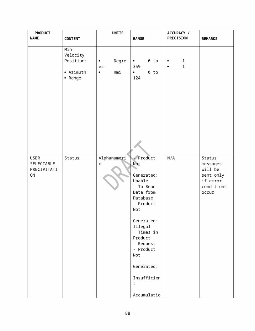
PRODUCT NAME CONTENT UNITS RANGE ACCURACY/PRECISION
REMARKS
Years: 0 to 99
Volume Scan Start Time
N/A Hours: 0 to 23Minutes: 0 to 59Seconds: 0 to 59
N/A
Elevation Degrees 0.0 to 20.0
0.1
Feature Status Alphanumeric
New (NEW), Extrapolated (EXT),Persistent (PER),Increasing (INC)
N/A NEW: Feature new this volume scan; EXT: Feature from previous scan with extrapolated position; PER: found in both previous and current volume; INC: Like PER but with increasing shear and/or Vortex Type.
Storm Cell ID Alphanumeric
A0 through Z0, then A1 through Z1, then A2....Z9
N/A The sequence is recycled followed Z9
Feature Type Alphanumeric
Uncorrelated Shear (UNC SHR), 3D Correlated Shear (3DC SHR), Mesocyclone
N/A " displayed when Feature Type from current volume
91

PRODUCT NAME CONTENT UNITS RANGE ACCURACY/PRECISION
REMARKS
(MESO)Mesocyclone Position: Azimuth Range
Degreesnmi
0 to 3600 to 124
11
"^" displayed when Position from current volume
Mesocyclone Height
Kft 0.0 to 33.1
0.1 "^" displayed when Height from current volume
Mesocyclone Base Value
Kft 0.0 to 33.1
0.1 "^" displayed when Base or Top from current volume
Mesocyclone Top Value
Kft 0.0 to 33.1
0.1 "^" displayed when Base or Top from current volume
Diameter (Radial) nmi 0 to 124 0.1 "^" displayed when Diameter from current volume
Diameter (Azimuthal)
nmi 0 to 780 0.1 "^" displayed when Diameter from current volume
Maximum Shear (tangential)
E-3/sec 0 to 999 1
MESOCYCLONE DETECTION
Radar ID N/A 0 to 999 1 Note 5.
Volume Scan Start Date
N/A Months: 1 to 12Days: 1 to 31Years: 0 to 99
N/A
Volume Scan Start Time
N/A Hours: 0 to 23Minutes: 0 to 59Seconds: 0 to 59
N/A
Average Motion: DirectionSpeed
Degrees Kts
0 to 360 0 to 129
11
Average of all MDA detected circulations regardless of whether they meet minimum display thresholds.
Circulation ID N/A 0 through 999
N/A The sequence is recycled following
92

PRODUCT NAME CONTENT UNITS RANGE ACCURACY/PRECISION
REMARKS
999Position: Azimuth Range
Degrees nmi
0 to 360 0 to 124
11
Base 2D feature component
Strength Rank N/A 1 to 25 1 If the strength rank was computed by the Low-Top or Shallow method, an L or S will also be displayed.
Associated SCIT Storm ID
N/A A0 through Z0,then A1 through Z1, then A2...Z9
N/A Closest SCIT identified storm cell ID.
Low Level (base) Rotational Velocity
Kts 0 to 129 1
Low Level (base) Gate-to-Gate Velocity Difference
Kts 0 to 129 1
Base Height (ARL)
Kft 0 to 33 1 If the Base is on the lowest elevation scan or below 1km, then the height is preceded by a "<" in the display.
Depth Kft 0 to 33 1 If the Base is on the lowest elevation scan or below 1km, then the Depth is preceded by a ">" in the display.
Storm Relative Depth Percentage
Percent 0 to 100 1 Based on the average depth of the ten SCIT identified storm cells having the highest cell based VIL.
Maximum Rotational Velocity
Kts 0 to 129 1
93

PRODUCT NAME CONTENT UNITS RANGE ACCURACY/PRECISION
REMARKS
Height of Maximum Rotational Velocity (ARL)
Kft 0 to 33 1
TVS N/A Y or N N/A Y if a TVS is detected within 2 km of Position
Motion deg/kts 0 to 360 deg0 to 99 kts
1 deg1 kt
Motion of this MDA detection or blanks if detection not tracked.
Mesocyclone Strength Index
N/A 0 to 99999
1 See MDA AEL.
TORNADO VORTEX SIGNATURE RAPID UPDATE (TRU)
Radar ID N/A 0 to 999 1
Volume Scan Start Date
N/A Months: 1 to 12Days: 1 to 31Years: 0 to 99
N/A
Volume Scan Start Time
N/A Hours: 0 to 23Minutes: 0 to 59Seconds: 0 to 59
N/A
Number of TVSs N/A 0 to 25 1 If the TRU identifies more than the (adaptable) maximum number of TVSs, then the number will be preceded by a ">"
Number of ETVSs N/A 0 to 25 1 If the TRU identifies more than the (adaptable) maximum number of ETVSs, then the number will be preceded by a ">"
Elevation degree -1.0 to 0.1
94

PRODUCT NAME CONTENT UNITS RANGE ACCURACY/PRECISION
REMARKS
45.0
Feature Status Alphanumeric
New (NEW),Extrapolated (EXT),Persistent (PER),Increasing (INC)
N/A NEW: Feature is new in this volume scan;EXT: Feature from previous volume scan with extrapolated position;PER: Feature found in both previous and current volume scan;INC:Like PER but with increasing in either LLDV, feature type, or depth.
Feature Type Alphanumeric
TVS or ETVS
N/A See Note 3
Storm Cell ID Alphanumeric
A0 through Z0, then A1 through Z1, then A2....Z9, or ??
N/A The sequence is recycled following Z9. "??" is displayed if the TVS or ETVS is not associated with a storm cell
Position: Azimuth Range
Degrees Nmi
0 to 359 0 to 124
1 1
See Note 3
Average Delta Velocity
kts 0 to 494 1 See Note 3
Low-level (base) kts 0 to 494 1 See Note 3
95
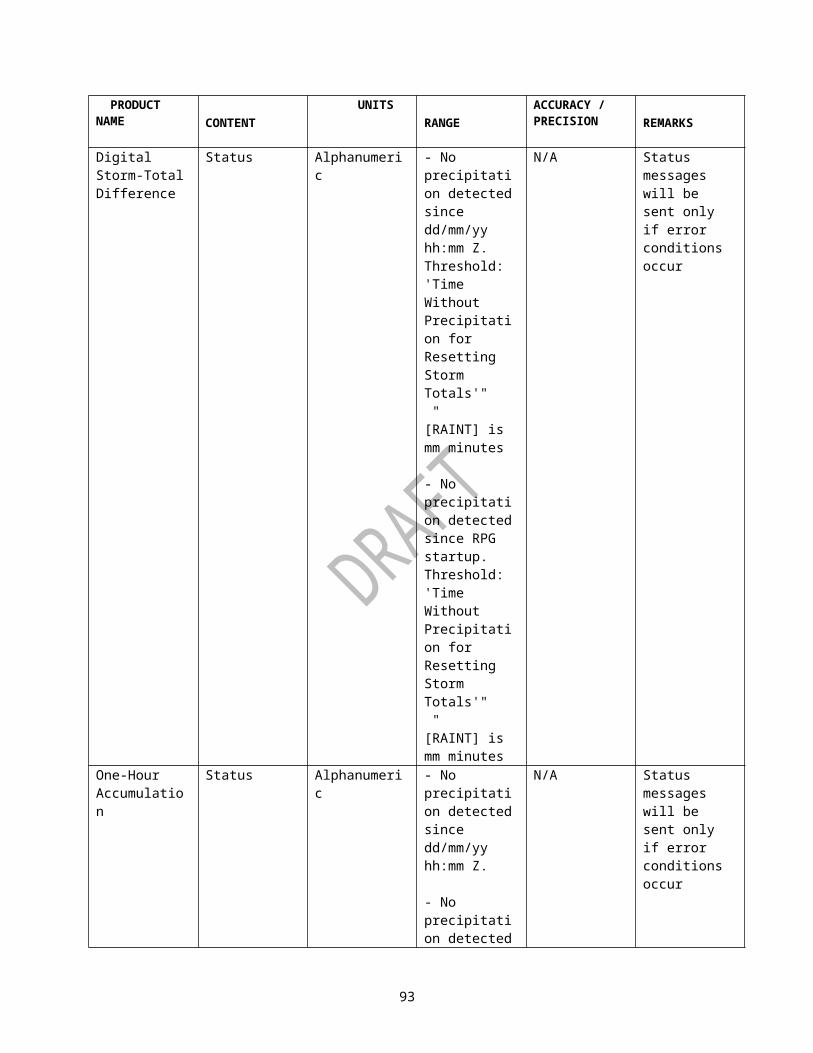
PRODUCT NAME CONTENT UNITS RANGE ACCURACY/PRECISION
REMARKS
Delta VelocityMaximum Delta Velocity
kts 0 to 494 1 See Note 3
Height of the Maximum Delta Velocity
kft 0.0 to 70.0
0.1 See Note 3
Depth kft 0.0 to 70.0
0.1 If the base or top is on the lowest or highest elevation scan, respectively then the Depth is preceded by a ">" in the display.
See Note 3Base Height kft 0 to 70 1 If the base is on
the lowest elevation scan, then it is preceded by a "<" in the display.
See Note 3Top Height kft 0.0 to
70.0.1 See Note 3
Maximum Shear m/s/km (or E-3/sec)
0 to 999 1 See Note 3
Height of the Maximum Shear
kft 0.0 to 70.0
0.1 See Note 3
One-hour Snow Water Equivalent and One-hour Snow Depth
RPG Name N/A N/A N/A
Date Month/Day/Year
Months: 1 to 12Days: 1 to 31Years: 00 to 99
N/A
Time Hours and Minutes UTC
Hours: 0 to 23Minutes 0
N/A
96
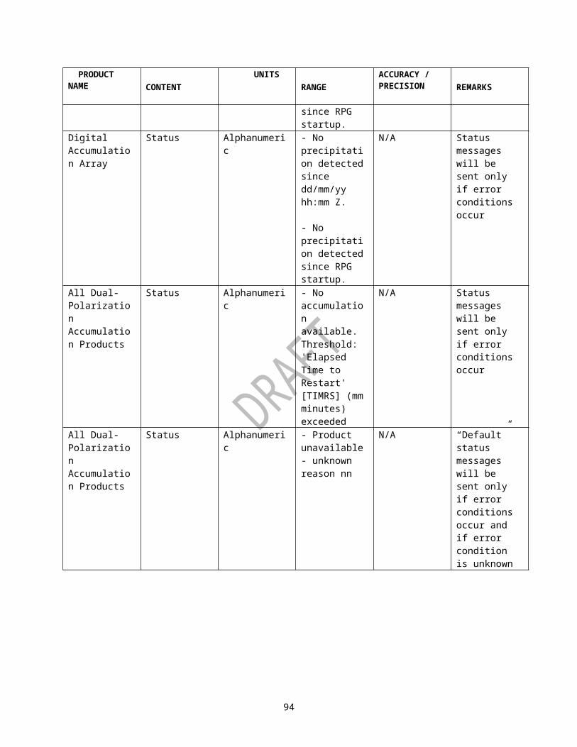
PRODUCT NAME CONTENT UNITS RANGE ACCURACY/PRECISION
REMARKS
to 59Starting Date Month/Day
/YearMonths: 1 to 12Days: 1 to 31Years: 00 to 99
N/A
Starting Time Hours and Minutes UTC
Hours: 0 to 23Minutes 0 to 59
N/A
Ending Date Month/Day/Year
Months: 1 to 12Days: 1 to 31Years: 00 to 99
N/A
Ending Time Hours and Minutes UTC
Hours: 0 to 23Minutes 0 to 59
N/A
Maximum Snow Accumulation
Inches 0 to 10**7
0.001 for Snow Water Equivalent and 0.01 for Snow Depth
Azimuth of Maximum Value
Degrees 0 to 359 1
Range to Maximum Value
Nmi 0 to 124 1
Range/height Correction Applied
N/A “Static” or “Used RCA”
Missing Time Minutes 0 to 60 1Site Adaptable Parameters and Configuration Parameters
N/A N/A N/A Page 2
Storm Total Snow Water Equivalent and Storm Total Snow Depth
RPG Name N/A N/A N/A
97

PRODUCT NAME CONTENT UNITS RANGE ACCURACY/PRECISION
REMARKS
Date Month/Day/Year
Months: 1 to 12Days: 1 to 31Years: 00 to 99
N/A
Time Hours and Minutes UTC
Hours: 0 to 23Minutes 0 to 59
N/A
Starting Date Month/Day/Year
Months: 1 to 12Days: 1 to 31Years: 00 to 99
N/A
Starting Time Hours and Minutes UTC
Hours: 0 to 23Minutes 0 to 59
N/A
Ending Date Month/Day/Year
Months: 1 to 12Days: 1 to 31Years: 00 to 99
N/A
Ending Time Hours and Minutes UTC
Hours: 0 to 23Minutes 0 to 59
N/A
Maximum Snow Accumulation
Inches 0 to 10**7
0.01 for Snow Water Equivalent and 0.1 for Snow Depth
Azimuth of Maximum Value
Degrees 0 to 359 1
Range to Maximum Value
Nmi 0 to 124 1
Range/height Correction Applied
N/A “Static” or “Used RCA”
98

PRODUCT NAME CONTENT UNITS RANGE ACCURACY/PRECISION
REMARKS
Missing Time Minutes 0 to 32767
1
Site Adaptable Parameters and Configuration Parameters
N/A N/A N/A Page 2
User Selectable Snow Water Equivalent and User Selectable Snow Depth
RPG Name N/A N/A N/A
Date Month/Day/Year
Months: 1 to 12Days: 1 to 31Years: 00 to 99
N/A
Time Hours and Minutes UTC
Hours: 0 to 23Minutes 0 to 59
N/A
Starting Date Month/Day/Year
Months: 1 to 12Days: 1 to 31Years: 00 to 99
N/A
Starting Time Hours and Minutes UTC
Hours: 0 to 23Minutes 0 to 59
N/A
Ending Date Month/Day/Year
Months: 1 to 12Days: 1 to 31Years: 00 to 99
N/A
Ending Time Hours and Minutes UTC
Hours: 0 to 23Minutes 0 to 59
N/A
Maximum Snow Accumulation
Inches 0 to 10**7
0.01 for Snow Water Equivalent and 0.1 for Snow Depth
Azimuth of Maximum Value
Degrees 0 to 359 1
99

PRODUCT NAME CONTENT UNITS RANGE ACCURACY/PRECISION
REMARKS
Range to Maximum Value
Nmi 0 to 124 1
Range/height Correction Applied
N/A “Static” or “Used RCA”
Site Adaptable Parameters and Configuration Parameters
N/A N/A N/A Page 2
STORM TOTAL ACCUMULATION
Radar ID N/A 4-digit alpha
N/A Radar ICAO
Volume Scan Date
N/A Months:1 to 12Days: 1 to 31Years: 0 to 99
N/A
Volume Scan Time
N/A Hours: 0 to 23Minutes: 0 to 59
N/A
Volume Coverage Pattern
N/A 1 to 1000 1
Operational (Weather) Mode
N/A A, B, or M N/A
Gage Bias Applied
N/A Yes or No N/A Note 4
Mean of Bias Estimates Computed During Accumulation Period
N/A 0.01 to 99.99
0.01 Note 4
Mean of G-R Pair Sample Sizes used in Bias Estimates During Accumulation Period
N/A 0.00 to 9999.99
0.01 Note 4
Mean of Memory Spans used in Bias Estimates During Accumulation Period
Hours 0.001 to 10**7
0.001 Note 4
Date/Time Last Bias Update
N/A Months:1 to 12Days: 1 to 31Years: 0 to 99
N/A Note 4
100

PRODUCT NAME CONTENT UNITS RANGE ACCURACY/PRECISION
REMARKS
Hours: 0 to 23Minutes: 0 to 59
Hybrid Rate Percent Bins Filled
Percentage
0.00 - 100.00
0.01
Highest Elev. Used
Degrees 0.5 - 19.5 0.1
Total Rain Area (Km**2)
km2 0.0 - 169,190.0
0.1
Site Adaptable Parameters
See Remarks
See Remarks
See Remarks
Information is always provided.
Note 1: Tabular Alphanumeric Block will display an adaptable number of storm cells.Note 2: This will be repeated each hour in the product.Note 3: “^” displayed when the attribute(s) is (are) updated to the current detection.Note 4. Gage bias is not being implemented for dual-polarization QPE products at this time. However, gage bias and its associated adaptable parameters will be implemented in the future. These parameters are used as placeholders.Note 5: When no mesocyclones are detected this negative condition will be indicated by the absence of this data block from the product.
101
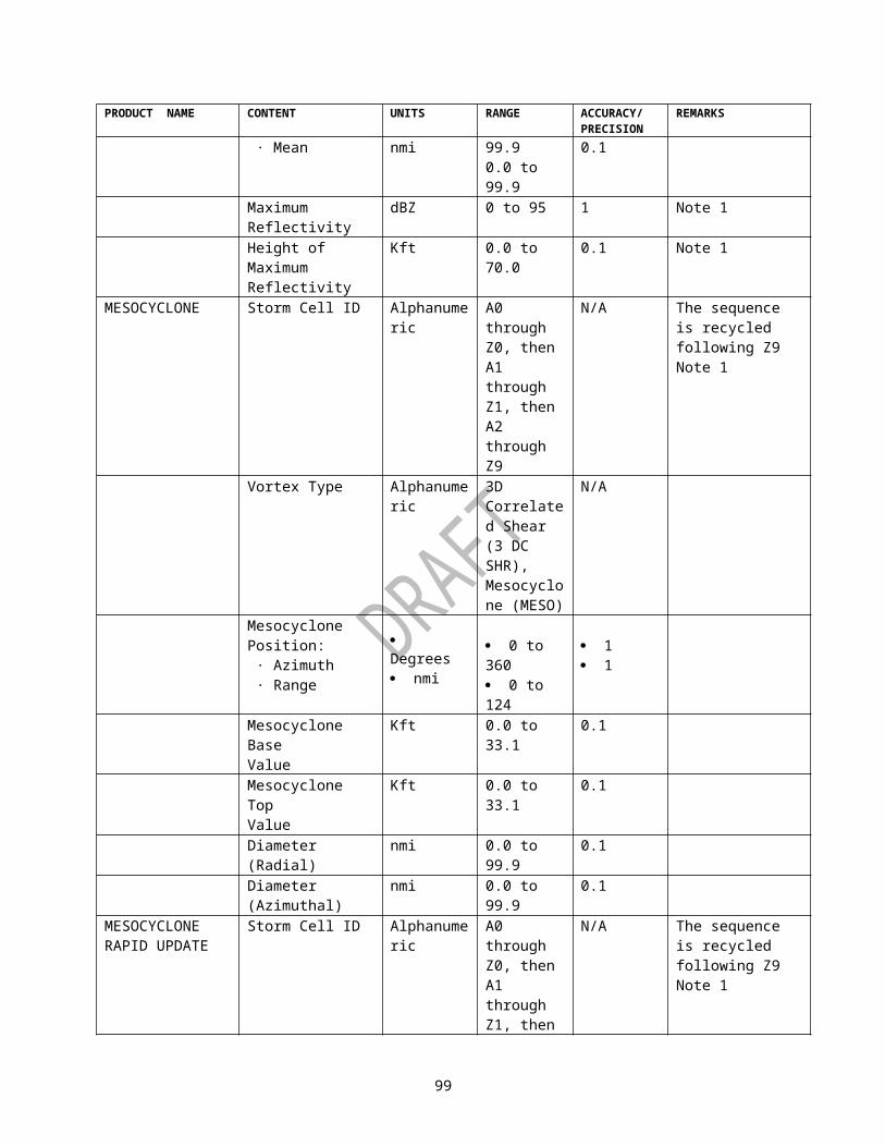
MSB HALFWORDNo Value
LSB
PACKET CODE (=6)LENGTH OF DATA BLOCK (BYTES)I STARTING POINT 1/4 Km orJ STARTING POINT Screen Coordinates
DATA END I VECTOR NUMBER 1BLOCK END J VECTOR NUMBER 1
END I VECTOR NUMBER 2END J VECTOR NUMBER 2
Figure 3-7 Linked Vector Packet - Packet Code 6 (Sheet 1)
MSB Uniform Value LSBPACKET CODE (=9)LENGTH OF DATA BLOCK (BYTES)VALUE (LEVEL) OF VECTORI STARTING POINT 1/4 KmJ STARTING POINT Screen Coordinates
DATA END I VECTOR NUMBER 1BLOCK END J VECTOR NUMBER 1
END I VECTOR NUMBER 2END J VECTOR NUMBER 2
Figure 3-7 Linked Vector Packet - Packet Code 9 (Sheet 2)
102

No ValueFIELDNAME TYPE UNITS RANGE PRECISION/
ACCURACYREMARKS
Packet Code INT*2 N/A 6 N/A Packet Type 6Length of Block
INT*2 Bytes 1 to 32767 1 Number of bytes in block not including self or packet code
I Starting Point
INT*2 Km/4 or Pixels -2048 to +2047
1 I coordinate for vector starting point
J Starting Point
INT*2 Km/4 or Pixels -2048 to +2047
1 J coordinate for vector starting point
End I Vector Number 1
INT*2 Km/4 or Pixels -2048 to +2047
1 I coordinate for vector end point 1
End J Vector Number 1
INT*2 Km/4 or Pixels -2048 to +2047
1 J coordinate for vector end point 1
End I Vector Number 2
INT*2 Km/4 or Pixels -2048 to +2047
1 I coordinate for vector end point 2
End J Vector Number 2
INT*2 Km/4 or Pixels -2048 to +2047
1 J coordinate for vector end point 2
Uniform ValueFIELDNAME TYPE UNITS RANGE PRECISION/
ACCURACYREMARKS
Packet Code
INT*2 N/A 9 N/A Packet Type 9
Length of Block
INT*2 Bytes 1 to 32767 1 Number of bytes in block not including self or packet code
Value (Level) of Vector
INT*2 N/A 0 to 15 1 Color Level of Vector
I Starting Point
INT*2 Km/4 or Pixels
-2048 to +2047
1 I coordinate for vector starting point
J Starting Point
INT*2 Km/4 or Pixels
-2048 to +2047
1 J coordinate for vector starting point
End I Vector Number 1
INT*2 Km/4 or Pixels
-2048 to +2047
1 I coordinate for vector end point 1
End J Vector Number 1
INT*2 Km/4 or Pixels
-2048 to +2047
1 J coordinate for vector end point 1
End I Vector Number 2
INT*2 Km/4 or Pixels
-2048 to +2047
1 I coordinate for vector end point 2
End J Vector Number 2
INT*2 Km/4 or Pixels
-2048 to +2047
1 J coordinate for vector end point 2
Figure 3-7. Linked Vector Packet - Packet Code 9 (Sheet 3)
103

MSB HALFWORD No Value
LSB
PACKET CODE (=7)
LENGTH OF DATA BLOCK (BYTES)
BEGINNING I VECTOR 1 1/4 KM
BEGINNING J VECTOR 1 OR
DATA END I VECTOR 1 SCREEN COORDINATES
BLOCK END J VECTOR 1
BEGINNING I VECTOR 2
BEGINNING J VECTOR 2
END I VECTOR 2
END J VECTOR 2
Figure 3-8. Unlinked Vector Packet - Packet Code 7 (Sheet 1)
104

MSB Uniform Value
LSB
PACKET CODE (=10)
LENGTH OF DATA BLOCK (BYTES)
VALUE (LEVEL) OF VECTORS
BEGINNING I VECTOR 1 1/4 KM
BEGINNING J VECTOR 1 OR
DATA END I VECTOR 1 SCREEN COORDINATES
BLOCK END J VECTOR 1
BEGINNING I VECTOR 2
BEGINNING J VECTOR 2
END I VECTOR 2
END J VECTOR 2
Figure 3-8. Unlinked Vector Packet - Packet Code 10 (Sheet 2)
105

No Value
FIELDNAME TYPE UNITS RANGEPRECISION/ACCURACY REMARKS
Packet Code INT*2 N/A 7 N/A Packet Type 7Length of Block INT*2 Bytes 1 to 32767 1 Number of bytes in
block not including self or packet code
Begin I Vector 1 INT*2 Km/4 or Pixels
-2048 to +2047
1 I coordinate for vector starting point 1
Begin J Vector 1 INT*2 Km/4 or Pixels
-2048 to +2047
1 J coordinate for vector starting point 1
End 1 Vector 1 INT*2 Km/4 or Pixels
-2048 to +2047
1 I coordinate for vector end point 1
End J Vector 1 INT*2 Km/4 or Pixels
-2048 to +2047
1 J coordinate for vector end point 1
Begin I Vector 2 INT*2 Km/4 or Pixels
-2048 to +2047
1 I coordinate for vector starting point 2
Begin J Vector 2 INT*2 Km/4 or Pixels
-2048 to +2047
1 J coordinate for vector starting point 2
End I Vector 2 INT*2 Km/4 or Pixels
-2048 to +2047
1 I coordinate for vector end point 2
End J Vector 2 INT*2 Km/4 or Pixels
-2048 to +2047
1 J coordinate for vector end point 2
Figure 3-8. Unlinked Vector Packet - Packet Code 7 (Sheet 3)
106

Uniform Value
FIELDNAME TYPE UNITS RANGEPRECISION/ACCURACY REMARKS
Packet Code INT*2 N/A 10 N/A Packet Type 10Length of Block INT*2 Bytes 1 to 32767 1 Number of bytes in
block not including self or packet code
Value (Level) of Vector
INT*2 N/A 0 to 15 1 Color Level of Vector
Begin I Vector 1 INT*2 Km/4 or Pixels
-2048 to +2047
1 I coordinate for vector starting point 1
Begin J Vector 1 INT*2 Km/4 or Pixels
-2048 to +2047
1 J coordinate for vector starting point 1
End 1 Vector 1 INT*2 Km/4 or Pixels
-2048 to +2047
1 I coordinate for vector end point 1
End J Vector 1 INT*2 Km/4 or Pixels
-2048 to +2047
1 J coordinate for vector end point 1
Begin I Vector 2 INT*2 Km/4 or Pixels
-2048 to +2047
1 I coordinate for vector starting point 2
Begin J Vector 2 INT*2 Km/4 or Pixels
-2048 to +2047
1 J coordinate for vector starting point 2
End I Vector 2 INT*2 Km/4 or Pixels
-2048 to +2047
1 I coordinate for vector end point 2
End J Vector 2 INT*2 Km/4 or Pixels
-2048 to +2047
1 J coordinate for vector end point 2
Figure 3-8. Unlinked Vector Packet - Packet Code 10 (Sheet 4)
107

MSBHALFWORDLinked Vectors
LSB MSBHALFWORDSet Color Levels
LSB
0 E 0 3 Packet Codes/OP Flags
0 8 0 2 Packet Codes
8 0 0 0 Initial PointIndicator
0 0 0 2 Color Value Indicator
I VALUE (LEVEL) OF CONTOURJLENGTH =# VECTORS x 4I1J1I2J2
MSBHALFWORDLinked Vectors LSB
3 5 0 1 Packet Codes/OP Flags
LENGTH =# VECTORS x 8IJI1J1IJI2J2Figure 3-8a Contour Vector Packet - Packet Codes 0E03, 0802 and 3501 (Sheet 1)
108

Set Color Levels:
FIELDNAME TYPE UNITS RANGEPRECISION/ACCURACY REMARKS
Packet Code INT*2 N/A 0802 (Hex) N/A Packet Type X'0802'Color Value Indicator INT*2 N/A 0002 (Hex) N/A Indicates that color
value is present in this packet
Value (Level) of Contour
INT*2 N/A 0 to 15 1 Color Level of Contour
Linked Contour Vectors:
FIELDNAME TYPE UNITS RANGEPRECISION/ACCURACY REMARKS
Packet Code INT*2 N/A 0E03 (Hex) N/A Packet Type X'0E03'Initial Point Indicator INT*2 N/A 8000 (Hex) N/A Indicates that initial
point is present in this packet
I Starting point INT*2 Km/4 -2048 to +2047
1 I coordinate for vector starting point
J Starting Point INT*2 Km/4 -2048 to +2047
1 J coordinate for vector starting point
Length of vectors INT*2 Bytes 4 to 32764 Multiples of 4 Length to follow in bytes (where length = # of vectors X4)
End I Vector Number 1
INT*2 Km/4 -2048 to +2047
1 I coordinate for vector end point 1
End J Vector Number 1
INT*2 Km/4 -2048 to +2047
1 J coordinate for vector end point 1
End I Vector Number 2
INT*2 Km/4 -2048 to +2047
1 I coordinate for vector end point 2
End J Vector Number 2
INT*2 Km/4 -2048 to +2047
1 J coordinate for vector end point 2
. . .
. . .Figure 3-8a Contour Vector Packet - Packet Codes 0802 and 0E03 (Sheet 2)
109
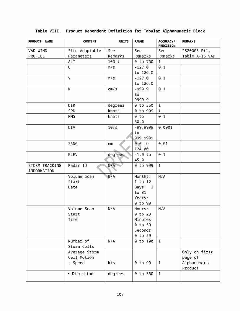
Unlinked Contour Vectors:
FIELDNAME TYPE UNITS RANGEPRECISION/ACCURACY REMARKS
Packet Code INT*2 N/A 3501 (Hex) N/A Packet Type X'3501'Length of Vectors INT*2 Bytes 8 to 32760 Multiples of 8 Length to follow in
bytes (where length = # of vectors X 8)
Begin I Vector 1 INT*2 Km/4 or Pixels
-2048 to +2047
1 I coordinate for vector starting point 1
Begin J Vector 1 INT*2 Km/4 or Pixels
-2048 to +2047
1 J coordinate for vector starting point 1
End 1 Vector 1 INT*2 Km/4 or Pixels
-2048 to +2047
1 I coordinate for vector end point 1
End J Vector 1 INT*2 Km/4 or Pixels
-2048 to +2047
1 J coordinate for vector end point 1
Begin I Vector 2 INT*2 Km/4 or Pixels
-2048 to +2047
1 I coordinate for vector starting point 2
Begin J Vector 2 INT*2 Km/4 or Pixels
-2048 to +2047
1 J coordinate for vector starting point 2
End I Vector 2 INT*2 Km/4 or Pixels
-2048 to +2047
1 I coordinate for vector end point 2
End J Vector 2 INT*2 Km/4 or Pixels
-2048 to +2047
1 J coordinate for vector end point 2
Figure 3-8a Contour Vector Packet - Packet Code 3501 (Sheet 3)
110
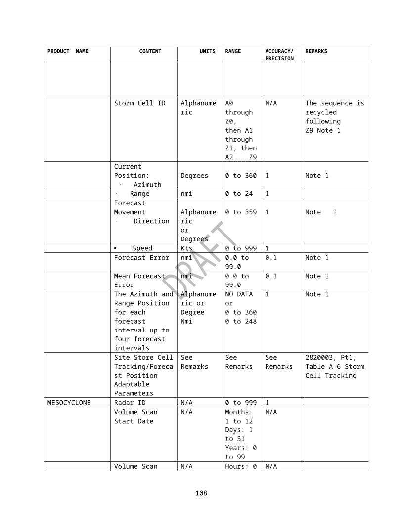
MSBHALFWORD Write Text (No Value) LSB
PACKET CODE (=1)
LENGTH OF DATA BLOCK (BYTES)
I STARTING POINT 1/4 KMDATA
J STARTING POINTScreen Coordinates
BLOCKCHARACTER 1 CHARACTER 2
CHARACTER 3 CHARACTER 4
CHARACTER N-1 CHARACTER NFigure 3-8b. Text and Special Symbol Packets - Packet Code 1 (Sheet 1)
111

MSBHALFWORD Write Text (Uniform Value)
LSB
PACKET CODE (=8)
LENGTH OF DATA BLOCK (BYTES)
VALUE OF TEXT STRING
I START1/4 KM
DATAJ START
Screen Coordinates
BLOCK CHARACTER 1 CHARACTER 2
CHARACTER 3 CHARACTER 4
CHARACTER N-1 CHARACTER NFigure 3-8b. Text and Special Symbol Packets - Packet Code 8 (Sheet 2)
112

MSBHALFWORD Write Special Symbols (No Value)
LSB
PACKET CODE (=2)
LENGTH OF DATA BLOCK (BYTES)
I STARTING POINT1/4 KM
DATAJ STARTING POINT
Screen Coordinates
BLOCK CHARACTER 1 CHARACTER 2
CHARACTER 3 CHARACTER 4
CHARACTER N-1 CHARACTER NFigure 3-8b. Text and Special Symbol Packets - Packet Code 2 (Sheet 3)
113

Write Text (No Value)
FIELDNAME TYPE UNITS RANGEPRECISION/ACCURACY REMARKS
Packet Code INT*2 N/A 1 N/A Packet Type 1Length of Block INT*2 Bytes 1 to 32767 1 Number of bytes in
block not including self or packet code
I Starting Point INT*2 Km/4 or Pixels
-2408 to +2047
1 I coordinate for text starting point
J Starting Point INT*2 Km/4 or Pixels
-2048 to +2047
1 J coordinate for text starting point
Character 1 to N Char 8 bit ASCII
ASCII Character Set
N/A Characters are ASCII
Write Text (Uniform Value)
FIELDNAME TYPE UNITS RANGEPRECISION/ACCURACY REMARKS
Packet Code INT*2 N/A 8 N/A Packet Type 8Length of Block INT*2 Bytes 1 to 32767 1 Number of bytes in
block not including self or packet code
Value (Level) of Text INT*2 N/A 0 to 15 1 Color Level of textI Starting Point INT*2 Km/4
or Pixels
-2048 to +2047
1 I coordinate for text starting point
J Starting Point INT*2 Km/4 or Pixels
-2048 to +2047
1 J coordinate for text starting point
Character 1 to N Char 8 bitASCII
ASCII Character Set
N/A Characters are ASCII
Figure 3-8b. Text and Special Symbol Packets - Packet Code 1 (Sheet 4)
114

Write Special Symbols (No Value)
FIELDNAME TYPE UNITS RANGEPRECISION/ACCURACY REMARKS
Packet Code INT*2 N/A 2 N/A Packet Type 2Length of Block INT*2 Bytes 1 to 32767 1 Number of bytes in
block not including self or packet code
I Starting Point INT*2 Km/4 or Pixels
-2048 to +2047
1 I coordinate for special symbol starting point (Note 1)
J Starting Point INT*2 Km/4 or Pixels
-2048 to +2047
1 J coordinate for special symbol starting point (Note 1)
Character 1 to N Char 8 bitASCII
ASCII Character Set
N/A Characters are ASCII
Note 1: I, J for special symbols are at the center of the symbol and at the upper left corner of the symbol for text.Note 2: The special symbol characters in use are: !(21), “(22), #(23), $(24), %(25) to report past storm cell position, current storm cell position, forecast storm cell position, past MDA position, and forecast MDA position, respectively. Where, the number in parenthesis is the 8-bit hexadecimal value for the ASCII character. The appearance of the special symbols (e.g., filled circles, plus marks, X within a circle) is described in the Product Specification ICD (2620003), sections 18.3.2 and 20.3.2.
Figure 3-8b. Text and Special Symbol Packets - Packet Code 2 (Sheet 5)
115

MSBHALFWORDLinked Vectors LSB MSB
HALFWORDText LSB
0 E 2 3 4 E 0 08 0 0 0 0 C 2 3I 8 0 0 0J XLENGTH = # VECTORS X 4 YI1 LENGTH OF C'sJ1 C1 C2I2 C3 C4J2
MSB Unlinked Vectors LSB MSB Special Symbols LSB3 5 2 1 4 E 0 1LENGTH # X 8 0 C 2 3I 8 0 0 0J XI1 YJ1 LENGTH OF C'sI C1 C2J C3 C4I2J2
Figure 3-9. Map Message Packet - Packet Codes 0E23, 4E00, 3521 and 4E01 (Sheet 1)
116

HALFWORD FIELDNAME TYPE UNITS RANGE
PRECISION/ACCURACY REMARKS
61 Block Divider INT*2 N/A -1 N/A Integer -1, Block Divider62 Map ID INT*2 N/A 132 to 198 1 Message code for
appropriate map from Table II
63 Data Format INT*2 N/A 1 N/A Integer 1 for RAMTEK format
64 Number of Data Pieces
INT*2 N/A 1, 17 1 Integer number of map segments; 1 = low resolution, 17 = high and low resolution
65-66 Total Byte Count
INT*4 Bytes 1 to 409600 1 Number of bytes in data pieces
67 Map Piece 1 Location
INT*2 N/A 1 to 32767 1 Map file sector number on RPG disk; offset from the beginning of map file to first piece of data on the disk
68-69 Byte Length of Map Piece 1
INT*4 Bytes 1 to 81920 1 The length of piece 1 in bytes
70-117 Note 1 Note 1 Note 1 Note 1 Note 1 Comparable to halfwords 67-69 for map piece 2 to 17; only when the high resolution map is included
118-127 Alignment Filler
INT*2 N/A 0 N/A Zero filled to halfword 128 from first byte of the message
129 Map Data Piece 1
Note 1 Note 1 Note 1 Note 1 Low resolution - contain packets shown in Sheet 1 of this figure
Map Data Piece 2
Note 1 Note 1 Note 1 Note 1 High resolution if included, contains packet shown in Sheet 1 of this figure
Map Data Piece 17
Note 1. Data pieces will be in the formats shown for: Linked Vectors (No Value), Unlinked Vectors (No Value), Write Text (No Value), and Write Special Symbols (No Value). The first 8 bytes will be replaced by the code shown in sheet 1 of this figure. The upper left corner of area of coverage is 0,0 and the resolution is 1/8 Km.
Figure 3-9. Map Message Packet - Packet Codes 0E23, 4E00, 3521 and 4E01 (Sheet 2)
117

MSB HALFWORD LSBA F 1 F PACKET CODEINDEX OF FIRST RANGE BINNUMBER OF RANGE BINSI CENTER OF SWEEPJ CENTER OF SWEEPSCALE FACTOR (230 / # OF RANGE BINS)NUMBER OF RADIALSNUMBER OF RLE HALFWORDS IN RADIAL
REPEAT FOR
RADIAL START ANGLE
EACH RADIAL
RADIAL ANGLE DELTA
RUN (0) COLOR CODE (0)
RUN (1) COLOR CODE (1)
RUN (2) COLOR CODE (2)
RUN (3) COLOR CODE (3)
·· ··RUN (N) COLOR
CODE (N)
0000 0000
Figure 3-10. Radial Data Packet (16 Data Levels) - Packet Code AF1F (Sheet 1)
118

Sectors or "Windows" Products will use this format with sufficient data to fill the requested area.
FIELDNAME TYPE UNITS RANGEPRECISION/ACCURACY REMARKS
Packet Code INT*2 N/A AF1F (Hex) N/A Packet Type X'AF1F'Index of First Range Bin
INT*2 N/A 0 to 460 1 Location of first range bin
Number of Range Bins
INT*2 N/A 1 to 460 1 Number of range bins comprising a radial
I Center of Sweep INT*2 Km/4 -2048 to +2047
1 I coordinate of center of sweep
J Center of Sweep INT*2 Km/4 -2048 to +2047
1 J coordinate of center of sweep
Scale Factor Scaled Integer
Pixels .001 to 8.000
.001 Number of pixels per range bin
Number of Radials INT*2 N/A 1 to 400 1 Total number of radials in products
Number of RLE Halfwords in Radial
INT*2 Halfword
1 to 230 1 Number of RLE (Run Length Encoded) 16-bit halfwords per radial
Radial Start Angle Scaled Integer
Degrees
0.0 to 359.9 .1 Starting angle at which radial data was collected; Scan is always in Clockwise direction
Radial Angle Delta Scaled Integer
Degrees
0.0 to 2.0 .1 Radial angle data
Run(0) 4 Bit INT
N/A 0 to 15 1 4-bit run code
Color Code(0) 4 Bit INT
N/A 0 to 15 1 4-bit color level
Figure 3-10. Radial Data Packet (16 Data Levels) - Packet Code AF1F (Sheet 2)
119

MSB HALFWORD LSBB A 0 F or 7 PACKET CODE8 0 0 0 / OP FLAGS0 0 C 0I COORDINATE STARTJ COORDINATE STARTX SCALE INTX SCALE FRACTIONALY SCALE INTY SCALE FRACTIONAL NUMBER OF ROWSPACKING DESCRIPTORNUMBER OF BYTES IN THIS ROW
REPEATFOR
RUN (0) COLOR CODE (0)
RUN (1) COLOR CODE (1)
EACH ROW
RUN (2) COLOR CODE (2)
RUN (3) COLOR CODE (3)
·· ··RUN (N) COLOR
CODE (N)
0000 0000
Figure 3-11. Raster Data Packet - Packet Codes BA0F and BA07 (Sheet 1)
120

FIELDNAME TYPE UNITS RANGEPRECISION/ACCURACY REMARKS
Packet Code INT*2 N/A BA0F (Hex) or BA07 (Hex)
N/A Packet Type X'BA0F' or X'BA07'
Packet Code INT*2 N/A 8000 (Hex) N/A Packet Type X'8000'Packet Code INT*2 N/A 00C0 (Hex) N/A Packet Type X'00C0'I Coordinate Start INT*2 Km/4 -2048 to
+20471 Starting location of
dataJ Coordinate Start INT*2 Km/4 -2048 to
+20471 Starting location of
dataX Scale INT INT*2 N/A 1 to 67 1 Scaling factor for
gridX Scale Fractional N/A N/A N/A N/A Reserved for
internal PUP useY Scale INT INT*2 N/A 1 to 67 1 Scaling factor for
gridY Scale Fractional N/A N/A N/A N/A Reserved for
internal PUP useNumber of Rows INT*2 N/A 1 to 464 1 Number of rows in
layerPacking Descriptor INT*2 N/A 2 N/A Defines packing
format 2Number of Bytes in this Row
INT*2 Bytes 2 to 920 1 Number of bytes in this row not including self
Run(0) 4 Bit INT N/A 0 to 15 1 4-bit run codeColor Code(0) 4 Bit INT N/A 0 to 15 1 4-bit color level
Figure 3-11. Raster Data Packet - Packet Codes BA0F and BA07 (Sheet 2)
121

MSB HALFWORD LSBPACKET CODE (=17)SPARESPARENUMBER OF LFM BOXES IN ROWNUMBER OF ROWS
REPEAT FOR NUMBER OF BYTES IN ROWEACH ROW RUN (0) LEVEL (01)
RUN (1) LEVEL (1)
RUN (N) LEVEL (N)
Figure 3-11a. Digital Precipitation Data Array Packet - Packet Code 17 (Sheet 1)
FIELDNAME TYPE UNITS RANGEPRECISION/ACCURACY REMARKS
Packet Code INT*2 N/A 17 N/A Packet Type 17Spares N/A N/A N/A N/ANumber of LFM Boxes in Row
INT*2 N/A 131 1 Number of boxes in each row
Number of Rows INT*2 N/A 131 1 Total number of rowsNumber of Bytes in Row
INT*2 N/A 2 to 262 1 Number of bytes in this row
Run(0) 1 Byte N/A 0 to 255 1 8-bit run codeLevel(0) 1 Byte N/A 0 to 255 1 8-bit data level code.
See Note 1 of Figure 3-6
Figure 3-11a. Digital Precipitation Data Array Packet - Packet Code 17 (Sheet 2)
122

MSB HALFWORD LSBPACKET CODE (=18)SPARESPARENUMBER OF LFM BOXES IN ROWNUMBER OF ROWS
REPEAT FOR NUMBER OF BYTES IN ROWEACH ROW RUN (0) LEVEL (0) RUN (1) LEVEL (1)
RUN (2) LEVEL (2) RUN (3) LEVEL (3)
RUN (N) LEVEL (N) 0000 0000Figure 3-11b. Precipitation Rate Data Array Packet - Packet Code 18 (Sheet 1)
FIELDNAME TYPE UNITS RANGEPRECISION/ACCURACY REMARKS
Packet Code INT*2 N/A 18 N/A Packet Type 18Spares N/A N/A N/A N/ANumber of LFM Boxes in Row
INT*2 N/A 13 1 Number of boxes in each row
Number of Rows INT*2 N/A 13 1 Total number of rowsNumber of Byes in Row
INT*2 N/A 2 to 14 1 Number of bytes in this row
Run(0) 4-Bit INT N/A 0 to 15 1 4-bit run codeLevel(0) 4-Bit INT N/A 0 to 15 1 4-bit data level code
Figure 3-11b. Precipitation Rate Data Array Packet - Packet Code 18 (Sheet 2)
123
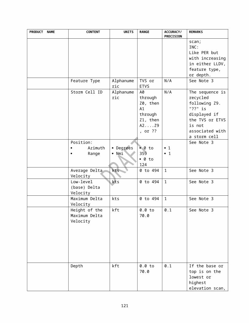
MSB HALFWORD LSBPACKET CODE (=16)INDEX OF FIRST RANGE BINNUMBER OF RANGE BINSI CENTER OF SWEEPJ CENTER OF SWEEPRANGE SCALE FACTOR NUMBER OF RADIALSNUMBER OF BYTES IN RADIALRADIAL START ANGLE
REPEAT RADIAL DELTA ANGLEFOR LEVEL (0) LEVEL (1)EACH LEVEL (2) LEVEL (3)RADIAL
LEVEL (N-1) LEVEL (N)
Figure 3-11c. Digital Radial Data Array Packet - Packet Code 16 (Sheet 1)
124

FIELDNAME TYPE UNITS RANGEPRECISION/ACCURACY REMARKS
Packet Code INT*2 N/A 16 N/A Packet Type 16Index of First Range Bin
INT*2 N/A 0 to 230 1 Location of first range bin
Number of Range Bins
INT*2 N/A 0 to 1840 1 Number of range bins comprising a radial
I Center of Sweep INT*2 Km/4 -2048 to +2047
1 I coordinate of center of sweep
J Center of Sweep INT*2 Km/4 -2048 to +2047
1 J coordinate of center of sweep
Range Scale Factor Scaled Integer
N/A .001 to 1.000
.001 Cosine of elevation angle for elevation based products. For volume based products the value 1.00.
Number of Radials INT*2 N/A 1 to 720 1 Total number of radials in product (Note 1)
Number of Bytes in Radial
INT*2 N/A 1 to 1840 1 Number of bytes of 8-bit data level values per radial
Radial Start Angle Scaled Integer
Degrees 0.0 to 359.9 .1 Starting angle at which radial data was collected; Scan is always clockwise
Radial Delta Angle Scaled Integer
Degrees 0.0 to 2.0 .1 Delta angle from previous radial
Level (0) 1 Byte N/A 0 to 255 1 8-bit data level code. (See Note 1 of Figure 3-6)
Note 1: The RPG clips radials to 70 kft. This could result in an odd number of bins in a radial. However, the radial will always be on a halfword boundary, so the number of bytes in a radial may be number of bins in a radial + 1.
Figure 3-11c. Digital Radial Data Array Packet - Packet Code 16 (Sheet 2)
125

MSB HALFWORD LSBPACKET CODE (=5)LENGTH OF DATA BLOCK (BYTES)
REPEAT I COORDINATEDATA FOR J COORDINATEBLOCK EACH DIRECTION OF ARROW
ARROW ARROW LENGTHARROW HEAD LENGTH
FIELDNAME TYPE UNITS RANGEPRECISION/ACCURACY REMARKS
Packet Code INT*2 N/A 5 N/A Packet Type 5Length of Block INT*2 Bytes 1 to 32767 1 Number of bytes in
block not including self or packet code
I Coordinate Point INT*2 Km/4 or Pixels
-2048 to +2047
1 Coordinate where the arrow and/or value is to be centered
J Coordinate Point INT*2 Km/4 or Pixels
-2048 to +2047
1 Coordinate where the arrow and/or value is to be centered
Direction of Arrow INT*2 Degrees 0 to 359 1 Arrow direction in 1-degree steps: points with wind field
Arrow Length INT*2 Pixels 1 to 512 1 Number of pixels in arrow
Arrow Head Length INT*2 Pixels 1 to 512 1 Number of pixels in arrow head
Figure 3-12. Vector Arrow Data Packet - Packet Code 5
126

MSB HALFWORD LSBPACKET CODE (=4)LENGTH OF DATA BLOCK (BYTES)
REPEAT VALUEDATA FOR X COORDINATEBLOCK EACH Y COORDINATE
BARB DIRECTION OF WINDWIND SPEED
FIELDNAME TYPE UNITS RANGEPRECISION/ACCURACY REMARKS
Packet Code INT*2 N/A 4 N/A Packet Type 4Length of Block INT*2 Bytes 1 to 32767 1 Number of bytes in
block not including self or packet code
Value INT*2 N/A 1 to 5 1 Color level of wind barb (reflects the RMS value associated with the computed velocity)
X Coordinate INT*2 Km/4 or Pixels
-2048 to +2047
1 Coordinate where the value starts
Y Coordinate INT*2 Km/4 or Pixels
-2048 to +2047
1 Coordinate where the value starts
Direction of Wind INT*2 Degrees 0 to 359 1 Points into windWind Speed INT*2 Knots 0 to 195 1 Magnitude of wind
Figure 3-13. Wind Barb Data Packet - Packet Code 4
127
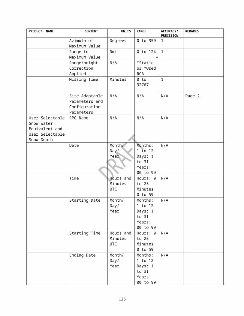
MSB HALFWORD LSBPACKET CODE (=3 or 11)
MESOCYCLONE LENGTH OF BLOCK (BYTES)REPEAT FOR I POSITIONEACH SYMBOL J POSITION
RADIUS OF MESOCYCLONE
MSB HALFWORD LSBPACKET CODE (=12 or 26)
TVS or ETVS LENGTH OF BLOCK (BYTES)REPEAT FOR I POSITIONEACH SYMBOL J POSITION
MSB HALFWORD LSBPACKET CODE (=13)
HAIL POSITIVE(FILLED) LENGTH OF BLOCK (BYTES)REPEAT FOR I POSITIONEACH SYMBOL J POSITION
MSB HALFWORD LSBPACKET CODE (=14)
HAIL PROBABLE LENGTH OF BLOCK (BYTES)REPEAT FOR I POSITIONEACH SYMBOL J POSITION
Figure 3-14. Special Graphic Symbol Packet - Packet Code 3 or 11, 12 or 26, 13 and 14 (Sheet 1)
128
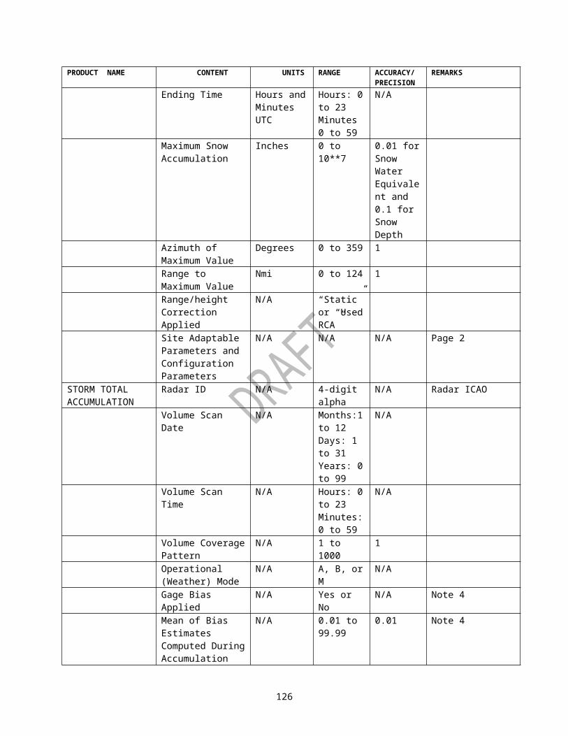
MSB HALFWORD LSBPACKET CODE (=15)
STORM ID LENGTH OF BLOCK (BYTES)REPEAT FOR I POSITIONEACH SYMBOL J POSITION
CHARACTER 1 CHARACTER 2
MSB HALFWORD LSBPACKET CODE (=19)
HDA HAIL LENGTH OF BLOCK (BYTES)REPEAT FOR I POSITIONEACH SYMBOL J POSITION
PROB. OF HAILPROB. OF SEVERE HAILMAX HAIL SIZE
MSB HALFWORD LSBSCIT PAST/ PACKET CODE (=23 or 24)FORECAST DATA LENGTH OF BLOCK (BYTES)
DISPLAY DATA PACKETS
MSB HALFWORD LSBPACKET CODE (=25)
STI CIRCLE LENGTH OF BLOCK (6 BYTES)I POSITIONJ POSITIONRADIUS OF CIRCLE
Figure 3-14. Special Graphic Symbol Packet - Packet Codes 15, 19, 23, 24 and 25 (Sheet 2)
129

FIELDNAME TYPE UNITS RANGEPRECISION/ACCURACY REMARKS
Packet Code INT*2 N/A 3, 11 to 15, 19, 23 to 26
N/A Packet Type (Note 1)
Length of Block INT*2 Bytes 1 to 32767 1 Number of bytes in block not including self or packet code
I Position INT*2 Km/4 -2048 to +2047
1 I starting coordinate
J Position INT*2 Km/4 -2048 to +2047
1 J starting coordinate
Radius of Mesocyclone
INT*2 Km/4 -2048 to +2047
1 A radius of 0 indicates that no mesocyclone is present and I, J coordinates are set to 0,0.
Character 1 Char 8-bitASCII
A to Z N/A First character of Storm ID
Character 2 Char 8-bitASCII
0 to 9 N/A Second character of Storm ID
Probability of Hail INT*2 N/A 0 to 100,-999
10 Probability in Percent (Note 2)
Probability of Severe Hail
INT*2 N/A 0 to 100,-999
10 Probability in Percent (Note 2)
Max Hail Size INT*2 Inches 0 to 4 1 Maximum expected hail size
Display Data Packet INT*2 N/A N/A N/A Past or forecast position data for a Single storm cell. Consists of packet code 2, (Figure 3-8b), packet code 6*(Figure 3-7) or packet code 25 (Figure 3-14)
Radius of STI Circle INT*2 Pixels 1 to 512 1 Radius of circle
Note 1.A packet code of 11 indicates 3-D correlated shear. Packet code 23 for past position data, packet code 24 for forecast position data, and packet code 25 for current position. Packet code 12 is for TVS position data and packet code 261 is for ETVS position data.Note 2.A value of -999 indicates that these cells are beyond the maximum range for algorithm processing.
Figure 3-14. Special Graphic Symbol Packet - Packet Codes 3, 11, 12, 13, 14, 15, 19, 23, 24, 25 and 26 (Sheet 3)
130

MSB HALFWORD LSBPACKET CODE (=20)LENGTH OF BLOCK (BYTES)
REPEAT FOR I POSITIONEACH SYMBOL J POSITION
POINT FEATURE TYPEPOINT FEATURE ATTRIBUTE
FIELDNAME
TYPE UNITS RANGE PRECISION/ACCURACY
REMARKS
Packet Code
INT*2 N/A 20 N/A Packet Type (Note 1)
Length of Block
INT*2 Bytes 8 to 32760
1 Number of bytes in block not including self or packet code
I Position
INT*2 Km/4 -2048 to +2047
1 I starting coordinate
J Position
INT*2 Km/4 -2048 to +2047
1 J starting coordinate
Point Feature Type
INT*2 N/A 1 to 4, 5 to 8, 9-11
1 1 = mesocyclone (extrapolated)2 = 3-D correlated shear (extrapolated)3 = mesocyclone (persistent, new, or increasing)4 = 3-D correlated shear (persistent, increasing, or new)5 = TVS (extrapolated)6 = ETVS (extrapolated)7 = TVS (persistent, new, or increasing)8 = ETVS (persistent, new, or increasing)9 = MDA Circulation with Strength Rank >= 5 AND with a Base Height <= 1 km ARL or with its Base on the lowest elevation angle.10 = MDA Circulation with Strength Rank >= 5 AND with a Base Height > 1 km ARL AND that Base is not on the lowest elevation angle. 11 = MDA Circulation with Strength Rank < 5
Point Feature Attribute
INT*2 Type dependent, see remarks.
Type dependent, see remarks.
Type dependent, see remarks.
For feature types 1-4, 9, 10, 11, radius in km/4
Figure 3-14. Special Graphic Symbol Packet - Packet Code 20 (Sheet 4)
131

MSB HALFWORD LSBPACKET CODE (=21)LENGTH OF BLOCK (BYTES)CELL ID C1 CELL ID C2I POSITIONJ POSITION
REPEAT FOR TREND CODEEACH TREND # VOLUMES LATEST VOL PTRCODE VOL. 1 TREND DATA
VOL N TREND DATA
FIELDNAME TYPE UNITS RANGEPRECISION/ACCURACY REMARKS
Packet Code INT*2 N/A 21 N/A Packet Type 21Length of Block INT*2 Bytes 12 to 198 1 Number of bytes to
follow in this packetCell ID C1 8 bit
ASCIIN/A A to Z N/A First character of
cell IDCell ID C2 8 bit
ASCIIN/A 0 to 9 N/A Second character of
cell IDI Position INT*2 Km/8 -4096 to
+40951 Cell I coordinate at
latest Volume ScanJ Position INT*2 Km/8 -4096 to
+40951 Cell J coordinate at
latest Volume ScanTrend Code INT*2 N/A 1 to 8 1 Indicates trend data
type to follow:1 = cell top2 = cell base3 = max. ref. hgt.4 = prob. hail5 = prob. svr. hail6 = cell based VIL7 = max. ref.8 = centroid hgt.
Figure 3-15. Cell Trend Data Packet - Packet Code 21 (Sheet 1)
132

FIELDNAME TYPE UNITS RANGEPRECISION/ACCURACY REMARKS
# Volumes INT*1 N/A 1 to 10 1 Number of volume scans of trend data for this trend code in the circular list
Latest Vol PTR INT*1 N/A 1 to 10 1 Pointer to the latest volume scan in the circular list
Vol 1 Trend Data INT*2 Note 1 Note 1 Note 1 Trend data for each scan in the circular list
Vol N Trend Data
TRENDCODE UNITS
SCALEFACTOR
SCALEDRANGE PRECISION REMARKS
1 Feet /100 0 to 1700 100 Feet Note 22 Feet /100 0 to 1700 100 Feet Note 23 Feet /100 0 to 700 100 Feet4 Percent 1 0 to 100 10 Percent Note 35 Percent 1 0 to 100 10 Percent Note 36 kg/m**2 1 0 to 100 1 kg/m**27 dBZ 1 0 to 75 1 dBZ8 Feet /100 0 to 700 100 FeetNote 1: The following defines the units, scale factor, range and precision for each trend code:Note 2: If the value is over 700, then 1000 has been added to denote that the CELL TOP (BASE) was detected on the highest (lowest) elevation scan.Note 3:Flag values of -999 denote that an UNKNOWN value (i.e. the cell is outside the maximum hail processing range).
Figure 3-15. Cell Trend Data Packet - Packet Code 21 (Sheet 2)
133

PACKET CODE (=22)CELL TREND LENGTH OF BLOCK (BYTES)VOLUME SCAN # VOLUMES LATEST VOL
PTRTIMES VOL TIME 1
VOL TIME N
FIELDNAME TYPE UNITS RANGEPRECISION/ACCURACY REMARKS
Packet Code INT*2 N/A 22 N/A Packet Type 22Length of Block
INT*2 Bytes 4 to 22 1 Number of bytes to follow in this packet
# Volumes INT*2 N/A 1 to 10 1 Number of cell trend volume scan times in the circular list
Latest Vol PTR INT*2 N/A 1 to 10 1 pointer to the latest cell trend volume scan time in the circular list
Vol Time 1 INT*2 Minutes 0 to 1439 1 Circular list of cell trend volume scan times in minutes after midnight (seconds are truncated)
Vol Time N
Figure 3-15a. Cell Trend Volume Scan Times - Packet Code 22
134

MSW HALFWORD LSBPACKET CODE (=27)LENGTH OF PACKET (MSW)LENGTH OF PACKET (LSW)ELEVATION ANGLELATITUDE (MSW)
REPEAT FOR LATITUDE (LSW)EACH SUPEROB CELL LONGITUDE (MSW)WITH AN AVERAGE LONGITUDE (LSW)RADIAL VELOCITY HEIGHT
AVERAGE RADIAL VELOCITYSTD OF THE AVERAGE RADIAL VELOCITYTIME DEVIATIONAVERAGE AZIMUTH
Figure 3-15b. SuperOb Wind Data Packet - Packet Code 27 (Sheet 1)
Packet 27 would be used in the Product Symbology Block. Each packet would represent a complete elevation scan. Multiple packets would be contained in a single data layer. If there is no data in the elevation scan, the packet “Length of Block” would be set to 2 bytes. There could be more packets than elevation angles in the VCPs since a mixture of VCPs result in reporting all the elevation angles which are separated by 0.35 degrees.Maximum packet size is based on full data coverage extending out to 100 km range and with spatial parameters of 2 degrees by 1 km is 324002 bytes. However, default adaptable parameters (5 km by 6 degrees) result in a maximum packet size of 21602 bytes.A SuperOb-cell is defined as a region bounded by adaptable range and azimuth limits (default 6 degrees by 10 km). The geographic center-point of cells are positioned at an azimuth and range at a multiples of ½ of the cell dimensions (e.g., 0 deg/5km, 0 deg/15km, … 6deg/5 km,… 354deg/95km). However, the position of the average radial velocity (i.e., latitude, longitude, height, and azimuth) is the average of the radar bin positions used in the average radial velocity computation.The product is generated once an hour (default) at 30 minutes past the hour regardless of the position of the antenna with the VCP.What if the radar data stops before the end of the time period, complete product at the scheduled time?If the radar is down for the full hour, don’t need to generate a product.
135

FIELDNAME TYPE UNITS RANGE PRECISION/ACCURACY
REMARKS
Packet Code INT*2 N/A 27 N/A Packet Code 27Packet Length (MSW) INT*4 Bytes 2 to 324002 1 Number of bytes to
follow in this packetElevation Angle INT*2 Degree
s-1.0 to +45.0 0.1 Angle of the Elevation
ScanLatitude (MSW)---------------------------------Latitude (LSW)
INT*4 Degrees
-90 to +90 0.001 North (+) or South (-) of the Equator of the cell
Longitude (MSW)---------------------------------Longitude (LSW)
INT*4 Degrees
-180 to +180 0.001 East (+) or West (-) of the Prime Meridian of the cell
Height INT*2 Meters -100 to 21336 1 Height above sea level of the cell
AVG Radial Velocity INT*2 Meters/Second
-127 to +126 0.01 Mean radial velocity for the cell
Standard Dev. of Ave. Radial Velocity
INT*2 Meters/Second
0 to 255 1 Standard deviation of mean velocity
Time Deviation INT*2 Seconds
-5400 to +5400
1 Deviation from Base Time of the average time of all velocity samples in the SuperOb cell
Azimuth Average INT*2 (Note 1)
Degrees
0 to 359 0.01 Average azimuth angle of all velocity samples in the SuperOb cell.
Note 1: The Azimuth Average is an unsigned 16-bit value.Figure 3-15b. SuperOb Wind Data Packet -- Packet Code 27 (Sheet 2)
136

PACKET CODE (=28, 29)RESERVED (=0)
GENERIC LENGTH OF DATA (BYTES)(MSHW)
DATA LENGTH OF DATA (BYTES) (LSHW)
PACKET START OF SERIALIZED DATASERIALIZED DATA HALFWORD 1SERIALIZED DATA HALFWORD N
FIELDNAME TYPE UNITS RANGEPRECISION/ACCURACY REMARKS
Packet Code INT*2 N/A 28 or 29 N/A Packet Type 28 or Packet Type 29
Reserved INT*2 N/A 0 N/A See Note 1Length of Serialized Data (MSHW)
INT*2 Bytes 0 to maximum 2-byte integer value
1 Number of bytes to follow in this packet (most significant halfword).
Length of Serialized Data (LSHW)
INT*2 Bytes 0 to maximum 2-byte integer value
1 Number of bytes to follow in this packet (least significant halfword).
Serialized Data
N/A N/A N/A N/A Serialized data returned from Generic Data Packet serializing function. See Note 2.
Note 1: Reserved for future use. Should be set to 0.Note 2: The serialized data is encoded using External Data Representation (XDR). The XDR Standard is defined in Request For Comments (RFC) 1832. The deserialized data format is defined by Generic Product Format described in Appendix E.
Figure 3-15c Generic Data Packet - Packet Codes 28 and 29 (Sheet 1)
MSB HALFWORD LSBMESSAGE HEADER BLOCK(see Figure 3-3)PRODUCT DESCRIPTION BLOCK
137

(see sheets 2, 6, & 7 of Figure 3-6)BLOCK DIVIDER (-1)NUMBER OF PAGES
REPEATFOR
REPEATFOR
NUMBER OF CHARACTERS
EACH PAGE
EACH LINE
CHARACTER DATA
END OF PAGE FLAG (-1)
FIELDNAME TYPE UNITS RANGE PRECISION/ACCURACY
REMARKS
Block Divider INT*2 N/A -1 N/A Integer value of -1, used to delineate this block from the header
Number of Pages INT*2 N/A 1 to 48 1 Total number of page
Number of Characters
INT*2 N/A 0 to 80 1 Number of characters in line
Character Data to N
Char 8 bit ASCII
ASCII Character Set
N/A Characters are ASCII
End of Page Flag INT*2 N/A -1 N/A Integer value of -1, to delineate end of page
Figure 3-16. Stand-Alone Tabular Alphanumeric Product Message
138

Table IX. Product Dependent Definition for Stand-Alone Tabular Alphanumeric Block
PRODUCT NAME CONTENT UNITS RANGE ACCURACY/PRECISION
REMARKS
STORM STRUCTURE
Radar ID N/A 0 to 999 N/A
Volume Scan Start Date
N/A Months: 1 to 12Days: 1 to 31Years: 0 to 99
N/A
Volume Scan Start Time
N/A Hours: 0 to 23Minutes: 0 to 59Seconds: 0 to 59
N/A
Number of Storms Cells
N/A 0 to 100 1
Storm Cell ID Alphanumeric
A0 through Z0,then A1 through Z1,then A2 ...Z9
N/A The sequence is recycled following Z9Note 1
Storm Positions: · Azimuth · Range
Degreesnmi
0 to 360 0 to 248
1 1
Note 1
Storm Base Kft 0.0 to 70.0 0.1 If the storm base was identified at the lowest elevation, the value is qualified with "<". Note 1
Storm Top Kft 0.0 to 70.0 0.1 If the storm top was identified at the highest elevation, the value is qualified with ">". Note 1
Cell Based VIL kg/m2 0 to 120 1 Note 1Maximum Reflectivity
dBZ 0 to 95 1 Note 1
Height of MaximumReflectivity
Kft 0.0 to 70.0 0.1 Note 1
Site Adaptable Parameters
See Remarks
See Remarks See Remarks
See Table LXVIII, SiteAdaptation Data inRadar ProductGeneration
139

PRODUCT NAME CONTENT UNITS RANGE ACCURACY/PRECISION
REMARKS
Program,2820003, Pt1.
USER ALERT MESSAGE
Radar ID N/A 0 to 999 N/A
Volume Scan Start Date
N/A Months: 1 to 12Days: 1 to 31Years: 0 to 99
N/A
Volume Scan Start Time
N/A Hours: 0 to 23Minutes: 0 to 59Seconds: 0 to 59
N/A
Alert Area N/A 1 or 2 1Position: · Azimuth · Range
Degreesnmi
0.0 to 359.90.0 to 250.0
0.1 0.1
Position is the alert grid box center for grid based alerts, feature base center for mesocyclone and TVS alerts, not applicable for VAD and 1 HR rainfall alerts, and Storm cell centroid for all other alerts.
Alert Category N/A See Table IV 1Alert Threshold See
RemarksSee Remarks See
RemarksSee Table LXVIII, SiteAdaptation Data inRadar ProductGeneration Program,2820003, Pt1
Exceeding Value
See Remarks
See Remarks See Remarks
See Table LXVIII, SiteAdaptation Data inRadar ProductGeneration Program,2820003, Pt1
Storm Cell ID Alphanumeric
A0 through Z0, then A1 through Z1, then A2....Z9
N/A Storm ID sequence isrecycled following Z9
140

PRODUCT NAME CONTENT UNITS RANGE ACCURACY/PRECISION
REMARKS
Forecast Movement · Direction · Speed
DegreesKts
" " or0 to 3600 to 999
11
" " indicates that theinformation isunavailable since alert is not related to a storm ID.
FREE TEXT MESSAGE
Message Text ASCII All ASCIICharacters
N/A
PUP TEXT MESSAGE
Message Text ASCII All ASCII Characters
N/A
SUPPLEMENTAL PRECIPITATION DATA
Radar ID N/A 0 to 999 N/A
Average Scan Date
N/A Months: 1 to 12Days: 1 to 31Years: 0 to 99
N/A
Average Scan Time
N/A Hours: 0 to 23Minutes: 0 to 59
N/A
No. Blockage Bins Rejected
N/A 0 to 99999 1
No. Clutter Bins Rejected
N/A 0 to 99999 1
No. Bins Smoothed
N/A 0 to 99999 1
Percent Hybrid Scan Filled
% 90.00 to 100.00 0.01
Highest Elev. Angle used in Hybrid Scan
Deg 0.50 to 19.50 0.01
Hybrid Scan Rain Area
Km**2 0.0 to 999999.9 0.1
Mean-field Bias Estimate
N/A .01 to 99.99 .01
Effective # Gage-Radar Pairs (Sample Size)
N/A 0.00 to 9999.99 .01
Memory Span used in Bias Estimate
Hours .001 to 10**7 .001
Bias Applied Flag
Alphanumeric
Yes or No N/A
Begin Missing Period Date
N/A Months: 1 to 12Days: 1 to 31Years: 0 to 99
N/A
Begin Missing Period Time
N/A Hours: 0 to 23Minutes: 0 to 59
N/A
End Missing Period Date
N/A Months: 1 to 12Days: 1 to 31
N/A
141

PRODUCT NAME CONTENT UNITS RANGE ACCURACY/PRECISION
REMARKS
Years: 0 to 99End Missing Period Time
N/A Hours: 0 to 23Minutes: 0 to 59
N/A
Volume Coverage Pattern
N/A 1 to 1000
Operational (Weather) Mode
N/A A, B or M N/A
Average Scan Date (Last Bias Update)
N/A Months: 1 to 12Days: 1 to 31Years: 0 to 99
N/A
Average Scan Time (Last Bias Update)
N/A Hours: 0 to 23Minutes: 0 to 59
N/A
Memory Span, per evaluation timespan
Hours 0.001 to 10**7 .001
Effective # Gage-Radar Pairs, per evaluation timespan
N/A 0.000 to 9999.999
.001
Average Gage Value, per evaluation timespan
mm 0.000 to 99.999 .001
Average Radar Value, per evaluation timespan
mm 0.000 to 99.999 .001
Mean-field Bias Estimate, per evaluation timespan
N/A 0.001 to 99.999 .001
142

MSB HALFWORD LSBMESSAGE HEADER BLOCK(see Figure 3-3)
GENERAL 10STATUS BLOCK (-1) BLOCK DIVIDER11 LENGTH OF BLOCK12 MODE OF OPERATION13 RDA OPERABILITY STATUS14 VOLUME COVERAGE PATTERN15 NUMBER OF ELEVATION CUTS1617·35
ELEVATION 1ELEVATION 2·ELEVATION 20
36 RDA STATUS37 RDA ALARMS38 DATA TRANSMISSION ENABLE39 RPG OPERABILITY STATUS40 RPG ALARMS41 RPG STATUS42 RPG NARROWBAND STATUS43 REFLECT. CALIB. CORR.44 PRODUCT AVAILABILITY45 SUPER RESOLUTION CUTS46 CLUTTER MITIGATION DECISION STATUS47 SPARE48 RDA BUILD NUMBER49 RDA CHANNEL NUMBER50 RESERVED51 RESERVED52 BUILD VERSION
Figure 3-17. General Status Message (Sheet 1)
143

HALFWORD FIELDNAME TYPE UNITS RANGE
PRECISION/ACCURACY REMARKS
10 Block Divider
INT*2 N/A -1 N/A Integer -1, block divider
11 Length of Block
INT*2 Bytes 82 1 Number of bytes to follow
12 Mode of Operation
INT*2 N/A 0 to 2 N/A Where:
0 = Maintenance Mode1 = Clear Air Mode2 = Precipitation/Severe Weather Mode
13 RDA Operability Status
Integer N/A 0,1/Bit Bit 15=LSB Where:
Bit 15=1 Automatic Calibration Disabled
Bit 14=1 OnlineBit 13=1 Maintenance
Action RequiredBit 12=1 Maintenance
Action Mandatory
Bit 11=1 Commanded Shutdown
Bit 10=1 InoperableBit 9 SpareBit 8=1 Wideband
DisconnectBits 7-0 SpareBits 15-10, 8=0
Indeterminate: if all bits are zero, then the RPG determines the status
14 Volume Coverage Pattern
INT*2 N/A 1 to 767 1 RDA Volume Coverage Pattern for the scan strategy being used
15 Number of Elevation
INT*2 N/A 1 to 20 1 Maximum elevation cuts =
144

HALFWORD FIELDNAME TYPE UNITS RANGEPRECISION/ACCURACY REMARKS
Cuts 20
16
.
.
.
Elevation 1 Scaled Integer
Degrees
-1.0 to +45.0
.1 Elevation angle elevation 1
35 Elevation 20
Scaled Integer
Degrees
-1.0 +45.0 .1 Elevation angle for elevation 20. NOTE: If the number of elevation cuts N, is less than 20, then elevations N+1 through 20 are zeros
36 RDA Status Integer N/A 0,1/Bit Bit 15=LSB Where:Bit 15 SpareBit 14=1 StartupBit 13=1 StandbyBit 12=1 RestartBit 11=1 OperateBit 10=1 SpareBit 9=1 Off-line OperateBit 8-0 SparesBits 14-9=0 Indeterminate; if
all bits are zero, then the RPG cannot determine the status
37 RDA Alarms Integer N/A 0,1/Bit,Note 1
Bit 15=LSB Where:
Bit 15=1 Indeterminate; the RPG cannot determine the alarms present
Bit 14=1 Tower/UtilitiesBit 13=1 PedestalBit 12=1 TransmitterBit 11=1 Receiver/Signal
ProcessorBit 10=1 RDA ControlBit 9=1 RDA
CommunicationsBit 8=1 SpareBit 7=1 SpareBits 6-0 SparesBits 15-7=0 No Alarms; if all
bits are zero, then
145

HALFWORD FIELDNAME TYPE UNITS RANGEPRECISION/ACCURACY REMARKS
there are no alarms present
38 Data Transmission Enabled
Integer N/A 0,1/Bit Bit 15=LSB Where:
Bit 15=1 SpareBit 14=1 NoneBit 13=1 ReflectivityBit 12=1 VelocityBit 11=1 Spectrum WidthBit 10=1 Dual Pol Data
ExpectedBits 9-0 Spares
39 RPG Operability Status
Integer N/A 0,1/Bit Bit 15=LSB Where:
Bit 15=1 LoadshedBit 14=1 On-lineBit 13=1 Maintenance
Action RequiredBit 12=1 Maintenance
Action MandatoryBit 11=1 Commanded
ShutdownBits 10 to 0 Spares
40 RPG Alarms Integer N/A Bit 15=LSB Where:Bit 15=1 No AlarmsBit 14=1 Node ConnectivityBit 13=1 SpareBit 12=1 RPG Control Task
FailureBit 11=1 Data Base FailureBit 10=1 SpareBit 9=1 RPG Input Buffer
Loadshed (Wideband)
Bit 8=1 SpareBit 7=1 Product Storage
LoadshedBit 6=1 SpareBit 5=1 SpareBit 4=1 SpareBit 3=1 RPG/RPG
Intercomputer Link Failure
Bit 2=1 Redundant Channel Error
Bit 1=1 Task FailureBit 0=1 Media Failure
146

HALFWORD FIELDNAME TYPE UNITS RANGEPRECISION/ACCURACY REMARKS
41 RPG Status Integer N/A 0,1/Bit Bit 15=LSB Where:Bit 15=1 RestartBit 14=1 OperateBit 13=1 StandbyBit 12=1 SpareBit 11=1 Test ModeBit 10-0 Spares
42 RPG Narrowband Status
Integer N/A 0,1/Bit Bit 15=LSB Where:
Bit 15=1 Commanded Disconnect
Bit 14=1 Narrowband Loadshed
Bit 13-0 Spares
43 Horizontal Channel Reflectivity Calibration Correction
Fixed Point, Scaled Integer
dB/4 -792 to +792 (-198 dB to +198 dB)
.25/1
Reflectivity Calibration Correction (difference from adaptation data)
44 Product Availability
Integer N/A 0,1/Bit Bit 15=LSB Where:
Bit 15=1 Product Availability
Bit 14=1 Degraded Availability
Bit 13=1 Not Available
45 Super Resolution Elevation Cuts
Integer N/A 0,1/Bit Bit 15 = LSBBit 15 = Elev 1
Bit field indicating which elevation cuts have super resolution enabled.
46 Clutter Mitigation Decision Status
Integer N/A 0,1/Bit Bit 15 = LSB
Where:
Bit 15 = 0 DisabledBit 15 = 1 EnabledBits 14-10 Bit field indicating
which elevation segments have Clutter Mitigation Decision enabled.
147

HALFWORD FIELDNAME TYPE UNITS RANGEPRECISION/ACCURACY REMARKS
47 Vertical Channel ReflectivityCalibration Correction
Fixed Point, Scaled Integer
dB/4 -792 to + 792(-198 dB to + 198 dB)
.25/1 Reflectivity CalibrationCorrection (difference from adaptation data)
48 RDA Build Number
Fixed Point, Scaled Integer
N/A 0 to 999, Note 2
N/A RDA major and minor build version information
49 RDA ChannelNumber
Integer N/A 0,1,2 N/A 0 = NWS single thread1 = RDA 12 = RDA 2for NWS redundant or FAA redundant
50-51 Reserved Halfword 50 & 51 are applicable to dial-up (Class II, Class IV, and Class V [RFC]) user only
52 Build Version
ScaledInteger
N/A 10 to 32767
RPG Build Version
Note 1: RDA Alarms reflect the controlling channel.Note 2: For Legacy RDA systems, this value will be 0. For Open RDA systems, the Build Version format is XX.Y where XX indicates the major build version and Y indicates the minor build version. This information is stored in scaled integer format. For example, Build 7.0 equals a value of 70. Build 99.9 equals a value of 999.
Figure 3-17. General Status Message (Sheet 2)
148

MSB HALFWORD LSBMESSAGE HEADER BLOCK(see Figure 3-3)
10 BLOCK DIVIDER (-1) REQUEST 11RESPONSE
LENGTH OF BLOCK
BLOCK 12
ERROR CODE (MSW)
13 (LSW)14 SEQUENCE NUMBER15 PRODUCT/MESSAGE CODE16 ELEVATION ANGLE17 VOLUME SCAN DATE18-19 VOLUME SCAN START TIME20-24 SPARES (7 HALFWORDS)
Figure 3-18. Request Response Message (Sheet 1)
149

HALFWORD FIELDNAME TYPE UNITS RANGEPRECISION/ACCURACY REMARKS
10 Block Divider
INT*2 N/A -1 N/A Integer -1, Block Divider
11 Length of Block
INT*2 Bytes 26 1 Number of bytes to follow
12-13 Error Code Integer N/A 0,1/Bit Bit 31=LSB Where:Bit 0=1 No Such Message
CodeBit 1=1 No Such Product
CodeBit 2=1 Product Not
Generated (Not Available in Data Base)
Bit 3=1 One-Time Request Generation Process Faulted
Bit 4=1 Narrowband Loadshed
Bit 5=1 Illegal RequestBit 6=1 RPG Memory
LoadshedBit 7=1 RPG CPU Loadshed
(Note 1)Bit 8=1 Unavailability of
Slots (Real-Time, Replay or Customized)
Bit 9=1 Failure (Task Failed)
Bit 10=1 Unavailable (Task Not Loaded Upon Startup)
Bit 11=1 Available Next Volume Scan
Bit 12=1 Moment DisabledBit 13 Bit 13 is Reserved
and Not Applicable to Associated PUPS
Bit 14 SpareBit 15 Aborted Volume
Scan (Note 2)
Bit 16 Invalid Product Parameters
Bit 17 Product Not Generated (Data Sequence Error) Note 3
150

HALFWORD FIELDNAME TYPE UNITS RANGEPRECISION/ACCURACY REMARKSBit 18 Task Failure (Self-
Terminated)Bits 19-31 Spares
14 Sequence Number
INT*2 N/A -13, 0 to 32767
1 Sequence number of request that caused response
15 Product/Message Code
INT*2 N/A -16 to -299,16 to 299
N/A Product/Message code as defined in Table II, that caused response
16 Elevation Angle
Scaled Integer
Degrees
-1.0 to +45.0
.1 Elevation angle of radar for requested product
17 Volume Scan Date
INT*2 Julian Date
1 to 32767 1 Modified Julian Date;integer number of days since Jan. 1, 1970
18-19 Volume Scan Start Time
INT*4 Seconds GMT
0 to 86399 1 Number of seconds after midnight, Greenwich Mean Time (GMT)
20-24 SparesNote 1: The RPG has not implemented the CPU Loadshed functionality that will generate an alarm.Note 2: The following conditions will cause ABORTED VOLUME SCAN: Commanded VCP Restart (either via operator command or Mode Deselection) or Unexpected Start of Volume Scan.Note 3: Product Not Generated (Data Sequence Error) is caused when VCP number changes unexpectedly, Azimuth Tolerance Exceeded in the initial elevation cut of volume, RDA Elevation Number Changes Unexpectedly, or Start of Elevation Y Expected, But Start Of Elevation received. In addition, any sequence error encountered during task processing …e.g. the task is not processing radial messages fast enough and its input buffers are lost at the expense of new input buffers.
Figure 3-18. Request Response Message (Sheet 2)
151

MSB HALFWORD LSBMESSAGE HEADER BLOCK(see Figure 3-3)
10 BLOCK DIVIDER (-1)11 ALERT STATUS12 ALERT AREA NUMBER13 ALERT CATEGORY14 THRESHOLD CODE15 THRESHOLD VALUE (MSW)16 THRESHOLD VALUE (LSW)17 EXCEEDING VALUE (MSW)18 EXCEEDING VALUE (LSW)19 GRID BOX AZIMUTH20 GRID BOX RANGE21 STORM CELL ID
C1STORM CELL ID C2
22 VOLUME SCAN NUMBER23 VOLUME SCAN DATE24 VOLUME SCAN START TIME (MSW)25 VOLUME SCAN START TIME (LSW)
Figure 3-19. Alert Message (Sheet 1)
152
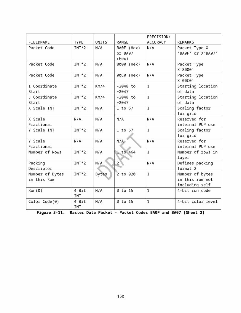
HALFWORD FIELDNAME TYPE UNITS RANGE
PRECISION/ACCURACY REMARKS
10 Block Divider INT*2 N/A -1 N/A Integer value of -1, used to delineate the header from the Alert Message Block
11 Alert Status INT*2 N/A 1 to 2 N/A 1 = First Time Alert2 = Alert Ended
12 Alert Area Number
INT*2 N/A 1 to 2 N/A Area number of alert as defined per user
13 Alert Category
INT*2 N/A 1 to 41 N/A Alert category number as defined by Table IV
14 Threshold Code
INT*2 N/A 1 to 6 N/A Parameter dependent threshold code that triggers alert (Refer to Table IV)
15-16 Threshold Value
INT*4 - - - Parameter dependent data value corresponding to the user defined threshold code (Refer to Table LXVIII in 2820003, Pt1)
17-18 Exceeding Value
INT*4 - - - Parameter dependent data value (maximum detected) which triggered the alert (Refer to Table LXVIII in 2820003, Pt1)
19 Grid Box Azimuth
Scaled Integer
Degrees 0.0 to 359.9
.1 Identifies the location of the grid box that triggered the alert. This halfword has no meaning for a cancelled alert.
20 Grid Box Range
Scaled Integer
Nmi 0.0 to 186.0
.1 Identifies the location of the grid box that triggered the alert. This halfword has no meaning for a canceled alert.
21 Storm ID C1 Char 8-bitASCII
A to Z, blank
N/A First character of Storm Cell ID associated with alert, when applicable (A-Z)
21 Storm ID C2 Char 8-bitASCII
0 to 9, blank
N/A Second character of Storm Cell ID
22 Volume Scan INT*2 N/A 1 to 80 1 Identifies the volume
153

HALFWORD FIELDNAME TYPE UNITS RANGE
PRECISION/ACCURACY REMARKS
Number scan when alert was triggered
23 Volume Scan Date
INT*2 Julian Date
1 to 32767
1 Identifies the volume scan date when the alert was triggered or canceled. (Modified Julian Date: integer number of days since Jan 1970.)
24-25 Volume Scan Time
INT*4 SecondsGMT
0 to 86399
1 Identifies the volume scan when the alert was time triggered or canceled. (Number of seconds after midnight, Greenwich Mean Time (GMT).)
Figure 3-19. Alert Message (Sheet 2)
154

MSB HALFWORD LSBMESSAGE HEADER BLOCK(see Figure 3-3)
10 BLOCK DIVIDER (-1)11 LENGTH OF BLOCKREPEAT FOR 12 ALERT GROUPEACH ALERT 13 ALERT CATEGORYCATEGORY 14 NUMBER OF ALLOWABLE THRESHOLDS(MAX = 41) 15·20
THRESHOLD 1·THRESHOLD 6
21 PRODUCT IDFigure 3-20. Alert Adaptation Parameters Message (Sheet 1)
155

HALFWORD FIELDNAME TYPE UNITS RANGE
PRECISION/ACCURACY REMARKS
10 Block Divider
INT*2 N/A -1 N/A Integer value of -1, used to delineate the header from the Alert Adaptation Data Parameters
11 Length of Block
INT*2 Bytes 820 1 Number of bytes to follow from -1 divider to end of block
12 Alert Group INT*2 N/A 0 to 3 1 1 = Grid Group2 = Volume Group3 = Forecast Group
13 Alert Category
INT*2 N/A 0 to 41 1 Alert category number as defined by Table IV
14 Number of Allowable Thresholds
INT*2 N/A 0 to 6 1 Parameter dependent threshold code that triggers alert (refer to Table IV)
15-20 Threshold Value
INT*2 - - - Parameter dependent data value corresponding to the user defined threshold code (refer to Table LVIII in 2820003, Pt1)
21 Product Code
INT*2 N/A 0, 16 to 299 1 Product Code as defined in Table III for product alert pairing, with the following exceptions:
Product Code of 91 corresponds to SWR(43), SWV(44), SWW(45), and SWS(46);
Product code of 92 corresponds to SWR(43), SRR(55), SWW(45), and SWS(46).
NOTE: The RPG transmits the Alert Adaptation Parameters Message upon Narrowband link connection, or if any changes are mad to either Product Alert Pairing or Alert Thresholds. Zero in range denotes spares.
Figure 3-20. Alert Adaptation Parameters Message (Sheet 2)
156

MSB HALFWORD LSBMESSAGE HEADER BLOCK(see Figure 3-3)
PRODUCT 10LIST
(-1) BLOCK DIVIDER
MESSAGE 11BLOCK
LENGTH OF BLOCK
12 NUMBER OF PRODUCTS13 RESERVEDREPEAT FOR 14 PRODUCT CODEEACH PRODUCT 15 ELEVATION16 PARAMETER 1 PRODUCT 17 PARAMETER 2 DEPENDENT18 PARAMETER 3 (SEE TABLE X)19 PARAMETER 420 DISTRIBUTION CLASS
Figure 3-21. Product List Message (Sheet 1)
157

HALFWORD FIELDNAME TYPE UNITS RANGE
PRECISION/ACCURACY REMARKS
10 Block Divider
INT*2 N/A -1 N/A Integer -1, block divider
11 Length of Block
INT*2 Bytes 4 to 8408 1 Number of bytes in block from -1 divider to end of the block.
12 Number of Products
INT*2 N/A 0 to 600 1 Number of Products on list
13 Reserved - - - - Reserved for dial-up users
14 Product Code
INT*2 N/A 16 to 299 1 Internal NEXRAD product code from Table III
15 Elevation Scaled Integer
Degrees
-1.0 to +45.0
.1 Elevation of product
16 Parameter 1 - - - - Product dependent (Refer to Table X)
17 Parameter 2 - - - - Product dependent (Refer to Table X)
18 Parameter 3 - - - - Product dependent (Refer to Table X)
19 Parameter 4 - - - - Product dependent (Refer to Table X)
20 Distribution Class
INT*2 N/A 0 to 20 1 Distribution class for individual products:0 = Available for one-time product request1 = Repeat every volume scan2 = Repeat every other volume scan9920 = Repeat every 20th volume scan
Figure 3-21. Product List Message (Sheet 2)
158

Table X. Product List Message Parameter Definition
Product Name(see Note 1)
MessageCode
SliceParameter 1 (see Note 2)
Parameter 2 (see Note 2)
Parameter 3 (see Note 2)
Parameter 4 (see Note 2)
Base Products 16-30 Elevation N/A N/A N/A N/AUser Selectable Layer Reflectivity
137 N/A Bottom Altitude of Layer
Top Altitude of Layer
N/A N/A
Cross Section 50, 51, 85, 86
N/A Azimuth of Point 1
Range of Point 1
Azimuth of Point 2
Range of Point 2
Storm Relative Mean Radial Velocity Region
55 Elevation Azimuth of Window Center
Range of Window Center
Storm Speed
Storm Direction
Storm Relative Mean Radial Velocity Map
56 Elevation N/A N/A Storm Speed
Storm Direction
Velocity Azimuth Display
84 Altitude N/A N/A N/A N/A
Mesocyclone Rapid Update
139 Elevation N/A N/A N/A N/A
Tornado Vortex Signature Rapid Update (TRU)
143 Elevation N/A N/A N/A N/A
User Selectable Snow Water Equivalent and User Selectable Snow Depth
150, 151
N/A End Hour Time Span N/A N/A
Differential Reflectivity
158-159
Elevation N/A N/A N/A N/A
Correlation Coefficient
160-161
Elevation N/A N/A N/A N/A
Specific Differential Phase
162-163
Elevation N/A N/A N/A N/A
Hydrometeor Classification
164-165
Elevation N/A N/A N/A N/A
Melting Layer 166 Elevation N/A N/A N/A N/ADigital User Selectable Accumulation
173 N/A End Time Time Span N/A N/A
Note l: The units, range and accuracy/precision for the above parameters are identical to the parameters listed in Table II- -A.Products that are completely defined by (message) product code (Slice and Parameters 1- -4 are N/A) are as follows: 32-- 41, 47, 48, 57- -75, 78-- 83 and 87-- 90.Note 2: For Parameters 1-4, if parameter is N/A, the value is undefined.
159
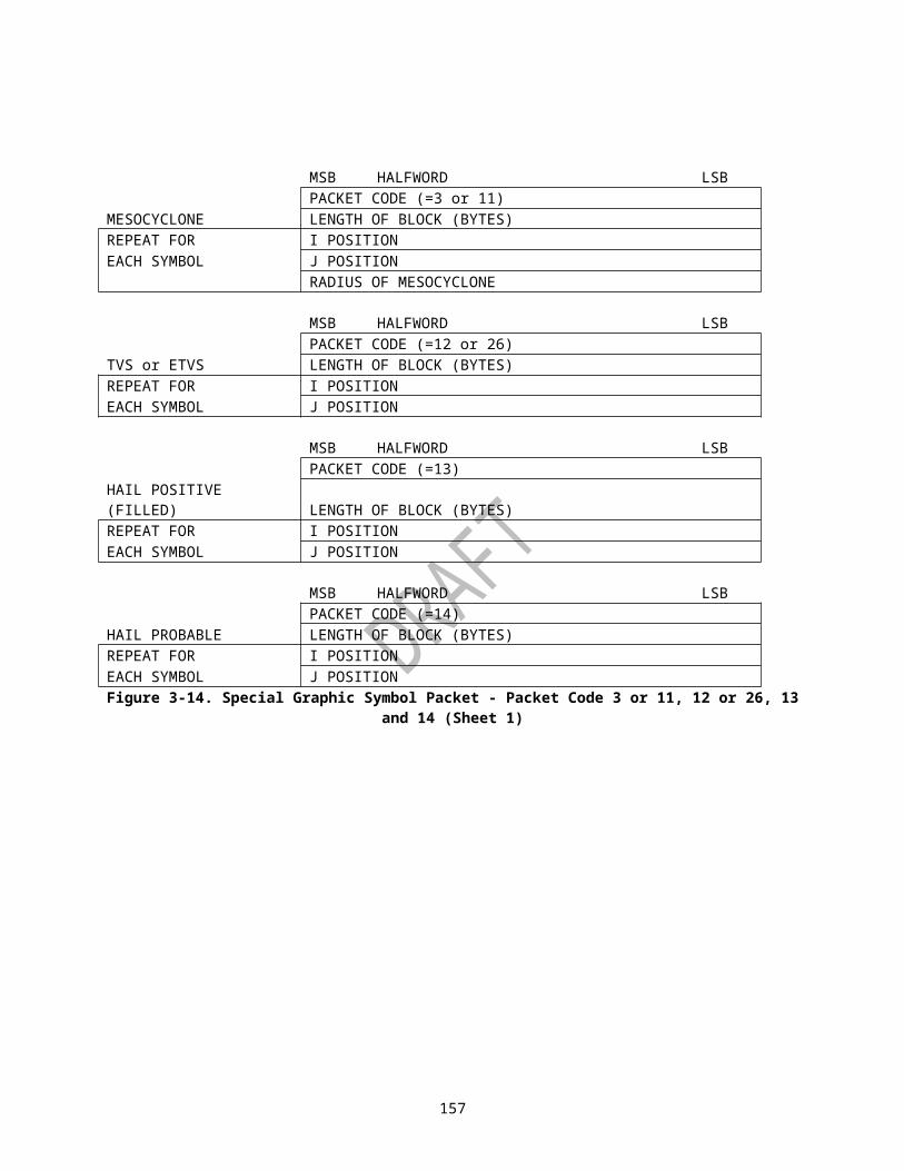
THE RADAR CODED MESSAGE MSB HALFWORD LSB
MESSAGE HEADER BLOCK(see Figure 3-3)
MESSAGE CODE = 74
PRODUCT DESCRIPTIONBLOCK
(Figure 3-6, Sheets 2, 6, & 7)
RADAR CODED MESSAGEHEADER
(see Appendix B)
BLOCK 3,TABULAR
ALPHANUMERIC
BLOCK
RADAR ENCODED MESSAGEDATABLOCK
Figure 3-22. Radar Coded Message
160

MSB HALFWORD LSBMessageHeaderBlock(See Figure 3-3)Block Divider (-1)Block IDSpareCompression TypeDecompressed Size (MSW)Decompressed Size (LSW)Data Packets See Figures 3-7
through 3-15c
Field Name Type Units Range Accuracy/Precision
Remarks
Block Divider
INT*2 N/A -1 N/A Integer value of -1 used to delineate this block from the Message Header block
Block ID INT*2 N/A 4 N/A Value of 4 indicates Environmental Data from 40-km RUC Model. See Note 1.
Spare INT*2 N/A N/A N/A SpareCompression Type
INT*2 N/A 0 to 2 1 0 = No compression, 1 = bzip2, 2 = zlib
Decompressed Size
INT*4 Bytes 0 to 2147483647
1/1 Size of decompressed data packets.
Note 1. For messages containing data from a source external to RPG (as indicated by Message Code 5 in Message Header), Block ID indicates specific type of External Data.
Figure 3-23. External Data Message
161

MSB HALFWORD LSBMessageHeaderBlock(See Figure 3-3)Block Divider (-1)Block ID (1)Version NumberBlock LengthAWIPS Site ID (MSW)AWIPS Site ID (LSW)Radar ID (MSW)Radar ID (LSW)Observation Time: YearObservation Time: MonthObservation Time: DayObservation Time: HourObservation Time: MinuteObservation Time: SecondGeneration Time: YearGeneration Time: MonthGeneration Time: DayGeneration Time: HourGeneration Time: MinuteGeneration Time: SecondNo. Rows (in Bias Table)Bias Table Row n: Memory Span (MSW)
REPEAT Bias Table Row n: Memory Span (LSW)Bias Table Row n: No. G-R Pairs (MSW)
FOR Bias Table Row n: No. G-R Pairs (LSW)Bias Table Row n: Avg. Gage (MSW)
EACH Bias Table Row n: Avg. Gage (LSW)Bias Table Row n: Avg. Radar (MSW)
ROW Bias Table Row n: Avg. Radar (LSW)Bias Table Row n: Mean Field Bias (MSW)
(MEMORY SPAN) Bias Table Row n: Mean Field Bias (LSW)Figure 3-25. Bias Table Message (Sheet 1)
162

Field Name Type Units Range Acc/Prec RemarksBlock Divider INT*2 N/A -1 N/A Integer value of -1 used to
delineate this block from the Message Header block
Block ID INT*2 N/A 1 N/A Value of 1 indicates "Bias Table" type of Environmental Data1
Version Number
INT*2 N/A 0 to 99 1 Initial=0, then 1, 2...
Block Length INT*2 N/A 70 to 270 1 Length of block in bytes (from -1 divider to end of block)
AWIPS Site ID (MSW)/AWIPS Site ID (LSW)
CHAR*4 N/A N/A N/A ID of AWIPS site (RFC or WFO) which originally computed the mean field bias (leading blank +3 chars)
Radar ID (MSW) /Radar ID (LSW)
CHAR*4 N/A N/A N/A ID of destination radar (leading blank +3 chars)
Observation Time: Year
INT*2 N/A 1970-2099
1 Ending date/time of Gage-Radar accum. period in Bias Table
Observation Time: Month
INT*2 N/A 1-12 1 "
Observation Time: Day
INT*2 N/A 1-31 1 "
Observation Time: Hour
INT*2 N/A 0-23 1 "
Observation Time: Minute
INT*2 N/A 0-59 1 "
Observation Time: Second
INT*2 N/A 0-59 1 "
Generation Time: Year
INT*2 N/A 1970-2099
1 Date/time of generation of Bias Table (will be later than Obs.time)
Generation Time: Month
INT*2 N/A 1-12 1 "
Generation Time: Day
INT*2 N/A 1-31 1 "
Generation Time: Hour
INT*2 N/A 0-23 1 "
Generation Time: Minute
INT*2 N/A 0-59 1 "
Generation Time: Second
INT*2 N/A 0-59 1 "
No. Rows (in Table)
INT*2 N/A 2-12 1 No. Memory Spans evaluated(default: 10)
Memory Span (MSW) /
Log, thenScaled
Hours .001 - 1. x 10**7
.001 Period of Gage-Radar Analysis
163

Field Name Type Units Range Acc/Prec RemarksMemory Span (LSW)
Int2
No. G-R Pairs (MSW) /No. G-R Pairs (LSW)
Scaled Integer
N/A .001 - 1. x 10**5
.001 Effective sample size(No. Gage-Radar Pairs)
Avg. Gage (MSW) /Avg. Gage (LSW)
Scaled Integer
mm 0.00-254.00
.001 Avg. Hourly Gage Accum.
Avg. Radar (MSW) /Avg. Radar (LSW)
Scaled Integer
mm 0.00-254.00
.001 Avg. Hourly Radar Accum.
Bias (MSW) / Bias (LSW)
Scaled Integer
N/A .01-100.00
.001 Mean-field Bias (Avg. Gage/Avg. Radar ratio)
1 For messages containing Environmental Data from external source to RPG (as indicated by Message Code 15 in Message Header), Message Block ID indicates specific type of Environmental Data.2 First take (natural) logarithm, then scale by 1000.
Figure 3-25. Bias Table Message (Sheet 2)
164

APPENDIX A. GLOSSARY
Acronym/Abbreviation DescriptionA Address SequenceABM Asynchronous Balanced ModeACCUM AccumulationADAPT AdaptationADM Asynchronous Disconnect ModeALT AltitudeANSI American National Standards InstituteARO Asynchronous Respond OpportunityASCII American Standard Code for Information
InterchangeAZ AzimuthBA Balanced, Asynchronous Balanced Mode (Same as
ABM)Beg BeginningBit Binary DigitBlock A related set of bytes containing control information
or data. A block is a component of a message.bps Bits per secondC Control SequenceCal CalibrationCALIB CalibrationCCITT Consultative Committee International Telephone
and TelegraphChar CharacterCKT CircuitCLIN Contract Line Item NumberCM Cubic MetersComp CompositeConst ConstantCPC Calcomp Pen CommandCPCI Computer Program Configuration ItemCPU Central Processor UnitCRC Cyclical Redundancy CheckingdBZ Reflectivity, in decibelsDCE Data Circuit-Terminating Equipmentdeg DegreeDig DigitalDir DirectionDISC DisconnectDM Disconnected ModeDTE Data Terminal EquipmentEIA Electronic Industries AssociationErr ErrorExt ExternalF or Flag Flag SequenceFCS Frame Check SequenceFlg Flag
A-1

Acronym/Abbreviation DescriptionFrame A segment of a bit stream bounded by a uniquely
recognizable bit sequence and containing a specified number of bits or bytes of data.
FRMR Frame RejectGFS General Format SpecifierGMT Greenwich Mean TimeHalfword Two bytes (16 bits)Header A set of bits or bytes contained in a bounded
segment of information which provides a label or control information to the remaining contents of the segment.
Hgt HeightHword Halfword (16 bits)I InformationI-field Information fieldI-frame Information frameICD Interface Control DocumentID IdentificationIEB Industrial Electronics BulletinINT*2 One halfword of integer data in standard 2' s
compliment formatINT*4 One fullword (32 bits) of integer data in standard
2's compliment formatInt IntegerInteg IntegratedInteger Bit stream of 1s and 0s, represented as an integer
number, not formatted in 2's compliment format (i.e., 32,768 integer code would represent setting the MSB of a halfword).
ISO International Organization for StandardizationITS Information Transfer Statekg Kilogramkm Kilometerkfs Kilofeetkts KnotsLAPB Link Access Procedure, BalancedLCG Logical Channel GroupLDS Logically Disconnected StateLFM Limited Fine MeshLiq LiquidLSB Least Significant BitLSW Least Significant WordMAX MaximumMessage The complete set of information transported from
the source to the destination. A message may be a product, product request, data, data request, or NEXRAD control information.
MSB Most Significant BitMsg MessageMSL Mean Sea LevelMSW Most Significant Word
A-2

Acronym/Abbreviation DescriptionN(r) Receive sequence variableN(s) Send sequence variableNMI Nautical MileN/A Not ApplicableNAVAIDS Navigational AidsNeg NegativeNEXRAD Next Generation Weather RadarNum NumberNTR NEXRAD Technical RequirementsOP OperationOS Operating SystemOSI Open Systems InterconnectionPDB Product Description BlockPos PositivePrec PrecipitationProb ProbabilityProduct A collection of information that is self contained and
provides a complete representation of a graphical image or an alphanumeric message.
PUP Principal User Processor GroupPVC Permanent Virtual CircuitRAD RadialRCM Radar Coded MessageRDA Radar Data Acquisition GroupReal*4 One fullword (32 bits) of real data, where the MSB is
the Sign-bit, followed by a 7 bit Exponent and a 24 bit Mantissa
Reflect ReflectivityReflect.Calib.Corr.
Reflectivity Calibration Correction
REJ RejectRES ResolutionRFC River Forecast CenterRGDAC Rain Gage Data Acquisition ComputerRLE Run Length EncodedRMS Root Mean SquareRNR Receiver Not ReadyRPG Radar Product Generation GroupRPGOP Radar Product Generator Operational PositionRR Receiver ReadySABM Set Asynchronous Balanced ModeScaled Integer Integer values with an assumed decimal point
whose position is defined by the precision of the item
SCN Specification Change NoticeSec SecondSD Snow Depthsq SquareSpd SpeedSPR Software Problem ReportSR Signaling Rate Selector
A-3

Acronym/Abbreviation DescriptionSW Spectrum WidthSWE Snow Water EquivalentSWP Severe Weather ProbabilityTAB TabularTM Test ModeTurb TurbulenceTWA Two-Way Alternate TransmissionTWS Two-Way Simultaneous TransmissionUA Unnumbered AcknowledgmentUCP Unit Control PositionUI Unnumbered FrameVAD Velocity Azimuth DisplayVar VariationVel VelocityVIL Vertically Integrated LiquidVME Versa Module EurocardVMECS Versa Module Eurocard Communication SubsystemWd WidthZBID Zero-Bit Insertion and Deletion
A-4

APPENDIX B. RADAR CODED MESSAGE
RADAR CODED MESSAGE CODEThe Radar Coded Message, as described in Item 26, Appendix E of the NTR, NEXRAD Products, will be composed of the following three parts, preceded by a communications header: Part A (Reflectivity), Part B (VAD Winds) and Part C (Remarks). In the groups below, capital letters represent the fixed part of the group, and small letters represent variables. The message will be encoded as follows:
HeaderThe header is encoded as follows:cccc Value is 1234. It is no longer the communications node (PUP
site identifier).ROBUU The product category for unedited radar coded message.sidd Four-letter RDA site identifier.
Part A: ReflectivityPart A of the Radar Coded Message (RCM) contains a tabular listing of alphanumerics. Data in the Radar Coded Message are located with respect to a polar stereographic grid. The local grid at each antenna site is designed to be a subset of the National Radar Grid so that data may be readily composited.The National Radar Grid has a resolution of LFM (Limited Fine Mesh model) which is 47.625 km at 60 degrees north latitude. The vertical axis of the grid is parallel to the 105 degrees west longitude meridian.At each site, a local grid is chosen having 25 rows and 25 columns, with the antenna site located within the central box. The 25 rows and columns of the grid are assigned letters A through Y, so that the box containing the antenna site is always box NM. Box AA is at the upper left. As shown in Figure D-1, each box is further subdivided to form an overall 1/16-LFM grid.The RCM is based on the 256-level, .54 nmi x 1 degree Composite or Hybrid Scan Reflectivity product but contains only nine data level categories; six for data within 124 nmi and one for missing or below threshold data and two for data beyond 124 nmi. Hybrid Scan Reflectivity data is used for the region within 124 nmi of the radar and Composite Reflectivity data is used for the region outside of 124 nmi. For data beyond 124 nmi, a separate threshold is provided for which: (a) all data above that threshold are labeled as level eight, and (b) all data below that threshold are labeled as level nine.
B-1

Figure B-1. 1/16 Limited Fine Mesh Model Grid
Within the tabular listing, data are provided for the maximum echo top. The height, and the position where provided, are derived from the Echo Tops product. The listing also shows the locations of the largest centroids within 124 nmi of the radar using the 1/16-LFM grid and provides the forecast centroid speed and direction, as available from the Storm Position Forecast algorithm. Part A of the message is encoded as follows:/NEXRAA Part A indicator.sidd Four letter RDA site identifier.ddmmyytttt The day (dd) of the month (mm), the year (yy) and the time (tttt) to
the nearest minute in Greenwich Mean Time (GMT).UNEDITED Status of message. The "edited" version no longer exists.RADNE A group to encode no reportable reflectivity intensity values shall be
provided; i.e., field NInnnn is zero. RADOM A group to encode radar down for maintenance shall be provided./MDnnnn A group of six characters to encode operational mode shall be
provided. See Appendix I of the NTR. Choices are PCPN and CLAR. (Example: /MDPCPN)
/SCnnnn A group of six characters to encode scan strategy shall be provided. Refer to Appendix I of NTR. Choices are 1405 (14 scans in 5 minutes), 0906, 0510, 1404, 0907, etc. (Example: /SC1405)
B-2

/NEXRAA Part A indicator./NInnnn: The total number (nnnn) of intensities (NI) reported in the following
field (gggi) shall be encoded. (Example: /NI0144:)gggi Reflectivity intensity shall be mapped onto the 1/16 LFM grid. Encode
locations and intensities by a series of groups made up of three letters (1/16 LFM followed by the maximum intensity of the designated grid box). The three letters (in order) shall be row, column, and sub-grid. The numbers following represent intensities in succeeding sub-grid boxes in that row; that is, encode each 1/16 LFM grid box from west to east, starting with the northern-most row with data, followed by the next southern row, etc. In the interest of compacting the message, successive intensities of different or similar values may be listed after a single location as long as the intensities are continuous. When succeeding sub-grid boxes contain the same intensity value, the number of succeeding boxes with the same value may be designated by a letter of the alphabet; that is, if four succeeding 1/16 LFM grid boxes (a total of five boxes) are at level 2, they could be coded as GGG2D. The "2D" may also be followed by different intensity values. Location/intensity groups shall be separated by a comma. (Example: ABF112D33l, BCA1211)
/MThhh:ggg The location and height (MSL) of the maximum echo top (MT) within 230 km radius of the radar shall be encoded using the three-letter grid designator (ggg) and assigning the height coinciding with echo top product in hundreds of feet (hhh). (Example: /MT320:NLB)
/NCENnn: The total number (nn) of centroids (NCEN) reported in this portion of the message shall be encoded. This number shall correspond to the corrected centroids below. (Example: /NCEN04:)
Cnnggg dddfff The centroid (C) number (nn), location (grid box) (ggg), direction from which it is moving (in 1-degree increments) (ddd), and its speed (fff) in knots, shall be encoded. Successive groups shall be separated by commas. If, during editing, data are deleted in a grid box that contains a centroid, this group shall be corrected by deleting this centroid. (Example: C03QMB240012)
/ENDAA(C/R) A group to indicate the end of Part A.The following is a summary example of the components of Part A:
/NEXRAA sidd ddmmyytttt UNEDITED/MDnnnn /SCnnnn /NInnnn:gggiii. . .i,gggiii...1/MThhh:ggg/NCENnn: Cnnggg dddfff, Cnnggg dddfff/ENDAA
B-3

Part B: VAD WindsPart B of the RCM contains a single profile of the horizontal wind information derived from the output of the VAD algorithm. Part B of the message is encoded as follows:
/NEXRBB Part B indicator.sidd Four letter RDA site identifier.ddmmyytttt The day (dd) of the month (mm), the year (yy), and the time (tttt), to
the nearest minute, in GMT.VADNA The optional entry VADNA shall be encoded for instances when no
VAD wind data available for the last 15 minutes, if appropriate.hhhcdddfff Coded heights (hhh) in hundreds of feet MSL; confidence 3 level,
using RMS for the coded height; wind direction (ddd) and wind speed (fff), in knots, shall coincide with those derived from the VAD Winds product. The confidence level shall be encoded as a single letter in accordance with the following:A = RMS of 2 kts; B = RMS of 4 kts;C = RMS of 6 kts; D = RMS of 8 kts;E = RMS of 10 kts; F = RMS of 12 kts;G = RMS of greater than or equal to 14 kts.
Wind direction and speed, as output from the VAD Algorithm, shall be reported at up to 19 heights, in feet MSL. Default heights are:1,000 6,000 12,000 25,0002,000 7,000 14,000 30,0003,000 8,000 16,000 35,0004,000 9,000 18,000 50,0005,000 10,000 20,000(Example: 080C240060)/ENDBB (C/R) End of Part B indicator.The following is a summary example of the components of Part B:
/NEXRBB sidd 2812881330 (C/R)hhhcdddfff ,hhhcdddfff ,hhhcdddfff/ENDBB (C/R)
B-4

Part C: RemarksPart C of the Radar Coded Message contains remarks in an alphanumeric format. Automatically generated remarks provide information on the locations of tornadic vortex signatures, mesocyclones, centroids, storm tops and hail indices. Part C is encoded as follows:/NEXRCC Part C indicator.sidd Four letter RDA site identifier.ddmmyytttt The day (dd) of the month (mm), the year (yy) and the time (tttt) to
the nearest minute in GMT./NTVSnn: The total number (nn) of Tornado Vortex Signatures (NTVS) detected
by the TVS algorithm and reported in Part C shall be encoded (Example: /NTVSO3:).
TVSnnggg The location (ggg) and number identifier (nn) of each Tornado Vortex Signature (TVS) shall be encoded using the three-letter grid box designator (Example: TVS02NLB).
/NMESnn: The total number (nn) of mesocyclones that meet or exceed the Minimum Display Filter Strength Rank threshold (default = strength rank 5) detected by the Mesocyclone Detection algorithm and reported in Part C shall be encoded (Example: /NMESO02:).
Mrrggg: The location (ggg) and strength rank (rr) of each mesocyclone that meets or exceeds the Minimum Display Filter Strength Rank threshold (M) shall be encoded using the three-letter grid box designator (Example: M05JLC).
/NCENnn: The total number (nn) of centroids (NCEN) reported in Part C shall be encoded (Example: /NCENO8:).
Cnnggg ShhhHi The height (hhh) in hundreds of feet (Above Ground Level - AGL), of the storm top(s), as derived from the Storm Cell Centroids algorithm, for each centroid identified in Part A to include location (ggg) shall be encoded. The centroid identifier number (nn) is the same as given in Part A. The hail (H) index (I), as provided by the Hail algorithm, is also given as one of the four following data levels:N - no hail (Probability of Severe Hail(POSH) = <30%P - possible or probable hail (50%>POSH>=30%H - hail (POSH >= 50%U - unknown
(Example: C04QQD S440HP).The following is a summary example of the components of Part C:
/NEXRCC sidd 2812881330 (C/R)/NTVSnn: TVSnnggg,TVSnnggg,TVSnnggg/NMESnn: Mnnggg,Mnnggg,Mnnggg/NCENnn: Cnnggg ShhhHi,Cnnggg ShhhHi,Cnnggg ShhhHi/UNEDITED:int
B-5

APPENDIX C. DATA TRANSMISSION CHARACTERISTICS
Table XI. Application Data Sizes
Typical Maximum Application Data Size Estimates (Note 1)Product Code
Mnemonic Message Size All VCPs
0 Prod. Req. For RPS list =.05 x # of prod on list. For OTR = .052 GSM .1243 Request
Resp..048
4 Max. Connect
.028
6 Alert Adapt. .0647 Alert Req. .5508 Prod. List .026 + (.014 x # of prod on list)9 Alert .0511 Sign On .03612 Request
PUP Status.018
13 Prod. Req. Cancel
.05
14 PUP Status .1NOTE 1: All product sizes are estimated maximum based on Build 4.0 testing and sizes are given in Kilobytes where (1 Kilobyte = 1024 bytes).
B-6

Table XII. VCP 11 Product Size
PRODUCT CODE
PRODUCT MNEMONIC ELEVATION
MIN SIZE(Bytes)
MAX SIZE(Bytes)
AVERAGE SIZE(Bytes)
MEDIAN SIZE(Bytes)
16 R 0.5 18968 19340 19170 1920016 R 1.5 17342 18026 17647 1764916 R 2.4 16528 17084 16819 1689716 R 3.4 14894 15594 15332 1530416 R 4.3 13668 14436 14029 1402417 R 0.5 16170 16510 16358 1640017 R 1.5 14046 14814 14408 1438817 R 2.4 12550 13052 12833 1288417 R 3.4 10882 11486 11241 1126618 R 0.5 10756 11150 10958 1094018 R 1.5 9636 10130 9873 984418 R 2.4 8504 8988 8765 881018 R 3.4 7706 8220 7990 801619 R 0.5 29130 29864 29634 2967419 R 1.5 27240 29048 28066 2786219 R 2.4 25510 26980 26197 2603619 R 3.4 22830 24200 23443 2353819 R 4.3 19546 22420 20802 2041620 R 0.5 22650 22938 22772 2274420 R 1.5 19974 21018 20413 2031020 R 2.4 17486 18278 17880 1784220 R 3.4 15136 16042 15571 1556621 R 0.5 14166 14360 14238 1421121 R 1.5 12828 13196 12987 1297721 R 2.4 11300 11580 11456 1147421 R 3.4 10218 10572 10371 1034822 V 0.5 19348 22158 21053 2117322 V 1.5 13556 14220 13881 1385822 V 2.4 12236 12938 12441 1237022 V 3.4 11672 12302 11970 1194823 V 0.5 17582 19530 18723 1878623 V 1.5 13310 13920 13651 1366323 V 2.4 12524 13038 12720 1268423 V 3.4 12186 12568 12305 1227824 V 0.5 16208 17562 17019 1722224 V 1.5 13210 13660 13438 1344824 V 2.4 12830 13630 13198 1311424 V 3.4 12040 12660 12373 1247424 V 4.3 11440 11700 11601 1161225 V 0.5 24624 26006 25339 2555825 V 1.5 17368 19570 18630 1879825 V 2.4 17388 18582 17913 1773025 V 3.4 16586 17406 16991 1699025 V 4.3 15680 16696 16186 1614626 V 0.5 23160 24180 23809 2389726 V 1.5 17974 20228 19162 1922726 V 2.4 18670 19896 19292 1932826 V 3.4 18110 19006 18522 1834427 V 0.5 20532 21612 21206 21278
B-7

PRODUCT CODE
PRODUCT MNEMONIC ELEVATION
MIN SIZE(Bytes)
MAX SIZE(Bytes)
AVERAGE SIZE(Bytes)
MEDIAN SIZE(Bytes)
27 V 1.5 17980 19294 18483 1842027 V 2.4 18614 18960 18733 1863627 V 3.4 17122 17606 17376 1745027 V 4.3 15862 16240 16011 1594628 SW 0.5 34794 36780 36112 3648628 SW 1.5 27902 30820 29331 2944428 SW 2.4 26578 30824 29083 2958228 SW 3.4 26538 29228 28146 2861429 SW 0.5 32464 33820 33199 3317329 SW 1.5 28452 30564 29706 2969029 SW 2.4 28704 31362 30148 3040829 SW 3.4 27994 30068 29170 2948230 SW 0.5 26132 27070 26640 2676430 SW 1.5 24322 25108 24749 2489230 SW 2.4 24882 25422 25186 2514630 SW 3.4 23496 24122 23784 2383230 SW 4.3 20960 22640 21958 2202431 USP 280 280 280 28032 DHR 40046 43286 41685 4173833 HSR 27466 28324 28044 2809435 CR 31862 32846 32288 3228536 CR 11060 11286 11176 1117737 CR 43324 44956 43854 4357238 CR 12542 12792 12648 1266441 ET 3180 3334 3243 324448 VWP 11532 11938 11820 1186450 RCS 636 1944 1300 132951 VCS 1326 2004 1525 137055 SRR 1680 2112 1892 188956 SRM 0.5 18812 20544 19704 1978756 SRM 1.5 17138 18590 17925 1806056 SRM 2.4 16710 19224 18012 1809356 SRM 3.4 15768 18390 16967 1672256 SRM 4.3 14690 17126 15910 1570857 VIL 2392 2504 2443 244458 STI 11078 18642 15575 1595659 HI 11676 12026 11831 1182660 M 3626 4928 4371 445261 TVS 3028 3428 3178 317862 SS 12696 17176 14948 1491463 LRA 3000 3192 3086 309064 LRA 3052 3288 3165 315265 LRM 3234 3424 3305 328166 LRM 2932 3002 2955 294867 APR 3030 3214 3122 309673 UAM 782 5380 2061 143874 RCM 2710 2780 2760 278078 OHP 5734 12696 11233 1198879 THP 12278 12278 12278 1227880 STP 17486 18112 17782 17746
B-8

PRODUCT CODE
PRODUCT MNEMONIC ELEVATION
MIN SIZE(Bytes)
MAX SIZE(Bytes)
AVERAGE SIZE(Bytes)
MEDIAN SIZE(Bytes)
81 DPA 2592 10984 8012 853882 SPD 2834 2834 2834 283484 VAD 3828 6702 5914 617689 LRA 2236 2386 2315 230890 LRM 3004 3086 3055 305093 DBV 0.5 44558 44558 44558 4455893 DBV 1.5 44558 44558 44558 4455893 DBV 2.4 44558 44558 44558 4455893 DBV 3.4 36650 36650 36650 3665093 DBV 4.3 29270 29350 29327 2935094 DR 0.5 45422 49361 47540 4742494 DR 1.5 41268 45532 43257 4307494 DR 2.4 34849 38184 36276 3610694 DR 3.4 29339 34208 31659 3152994 DR 4.3 24316 30184 27288 2751895 CRE 24032 28696 27745 2824696 CRE 6574 11118 10340 1093897 CRE 31520 36152 34731 3507498 CRE 7946 12504 11700 1228499 DV 0.5 84409 94614 87733 8723899 DV 1.5 79320 86532 81680 8062099 DV 2.4 77767 87576 81842 8152299 DV 3.4 74043 85500 78812 7896999 DV 4.3 64770 79918 72260 73260132 CLR 0.5 38626 40314 39584 39568132 CLR 1.5 39252 40008 39594 39596132 CLR 2.4 33556 34138 33871 33836132 CLR 3.4 29284 30054 29717 29872132 CLR 4.3 24890 27272 26082 25944133 CLD 0.5 31492 32390 31928 32074133 CLD 1.5 30546 31892 31424 31416133 CLD 2.4 29900 31218 30582 30604133 CLD 3.4 29400 30902 30141 30194133 CLD 4.3 26886 29438 28336 28240134 DVL 46993 47780 47439 47437135 EET 24167 24855 24543 24523136 SO 126736 138016 132376 132376137 ULR 15140 23998 19750 19720138 DSP 44676 44676 44676 44676139 MRU 0.5 1320 5030 3559 3786139 MRU 1.5 2834 5122 3912 4076139 MRU 2.4 2846 5204 4040 4146139 MRU 3.4 2916 5214 4221 4228139 MRU 4.3 2950 5628 4346 4240139 MRU 5.3 2950 5708 4352 4272139 MRU 6.2 2950 5708 4430 4782139 MRU 7.5 2950 5730 4467 4826139 MRU 8.7 2950 5730 4495 4848139 MRU 10.0 2950 5730 4500 4848139 MRU 12.0 2950 5730 4501 4848
B-9

PRODUCT CODE
PRODUCT MNEMONIC ELEVATION
MIN SIZE(Bytes)
MAX SIZE(Bytes)
AVERAGE SIZE(Bytes)
MEDIAN SIZE(Bytes)
139 MRU 14.0 2950 5730 4501 4848139 MRU 16.7 2950 5730 4501 4848139 MRU 19.5 2094 4816 3601 3786141 MD 120 3120 2030 2022143 TRU 0.5 120 1870 1438 1558143 TRU 1.5 120 1870 1438 1558143 TRU 2.4 120 1870 1528 1558143 TRU 3.4 120 1870 1549 1662143 TRU 4.3 120 1870 1552 1662143 TRU 5.3 120 1870 1552 1662143 TRU 6.2 120 1870 1552 1662143 TRU 7.5 120 1870 1552 1662143 TRU 8.7 120 1870 1552 1662143 TRU 10.0 120 1870 1552 1662143 TRU 12.0 120 1870 1552 1662143 TRU 14.0 120 1870 1552 1662143 TRU 16.7 120 1870 1552 1662143 TRU 19.5 120 1870 1438 1558144 OSW 2836 30442 21748 29077145 OSD 2836 28706 20813 27721146 SSW 15496 22940 19808 20308147 SSD 15538 20266 18197 18516149 DMD 0.5 3103 4417 3659 3607149 DMD 1.5 3354 4798 4153 4201149 DMD 2.4 4081 5830 4970 4986149 DMD 3.4 4338 6524 5439 5426149 DMD 4.3 4605 6869 5646 5650149 DMD 5.3 4665 7169 5888 5879149 DMD 6.2 4674 7450 6076 6190149 DMD 7.5 4656 7671 6209 6295149 DMD 8.7 4658 7859 6287 6470149 DMD 10.0 4675 7851 6363 6573149 DMD 12.0 4918 7997 6417 6690149 DMD 14.0 4900 7982 6464 6740149 DMD 16.7 4869 8169 6496 6746149 DMD 19.5 4935 8155 6478 6622150 USW 3082 3082 3082 3082151 USD 3082 3082 3082 3082
B-10

Table XIII. VCP 12 Product Size
PRODUCT CODE
PRODUCT MNEMONIC ELEVATION
MIN SIZE(Bytes)
MAX SIZE(Bytes)
AVERAGE SIZE(Bytes)
MEDIAN SIZE(Bytes)
16 R 0.5 14334 17910 16264 1647516 R 0.9 12086 17910 15164 1524216 R 1.3 10036 16314 12527 1200316 R 1.8 9904 11094 10610 1082017 R 0.5 12746 13846 13257 1330217 R 0.9 11158 13846 12623 1282617 R 1.3 9704 13090 11247 1118217 R 1.8 8776 9960 9409 949018 R 0.5 8158 8710 8589 861718 R 0.9 7122 8710 8143 802718 R 1.3 6534 7896 7398 751618 R 1.8 6158 6978 6571 655418 R 2.4 5754 6426 6098 606619 R 0.5 16950 22954 20172 2048919 R 0.9 13654 22954 18257 1819919 R 1.3 11152 18940 14268 1333719 R 1.8 10978 12204 11746 1184419 R 2.4 11196 12550 11881 1200620 R 0.5 14472 17398 15874 1584820 R 0.9 12400 17398 14774 1477920 R 1.3 10360 15132 12450 1212420 R 1.8 9404 10552 10081 1019220 R 2.4 8934 10070 9551 975821 R 0.5 9486 10838 10085 1004921 R 0.9 8308 10838 9439 941221 R 1.3 6890 9338 8164 815121 R 1.8 6518 7328 6966 699822 V 0.5 28006 35776 29280 2891722 V 0.9 18934 35776 25629 2802522 V 1.3 16914 28270 20763 2106822 V 1.8 17074 20626 19317 1969223 V 0.5 23410 32676 25994 2538423 V 0.9 16638 32676 22893 2348723 V 1.3 15430 24450 18582 1838423 V 1.8 15100 17278 16412 1648424 V 0.5 17936 22346 19335 1890224 V 0.9 13856 22346 17552 1793624 V 1.3 13508 17746 15273 1530924 V 1.8 13372 14898 14263 1438225 V 0.5 32152 34528 33610 3376225 V 0.9 23996 34528 30744 3102725 V 1.3 21398 29902 26948 2822125 V 1.8 20028 28042 25449 2629826 V 0.5 27238 31100 29223 2924726 V 0.9 20308 31100 26517 2684826 V 1.3 18754 26458 22823 2341326 V 1.8 17014 22482 20598 2104827 V 0.5 20340 22658 21313 2127127 V 0.9 16258 22658 19749 20340
B-11
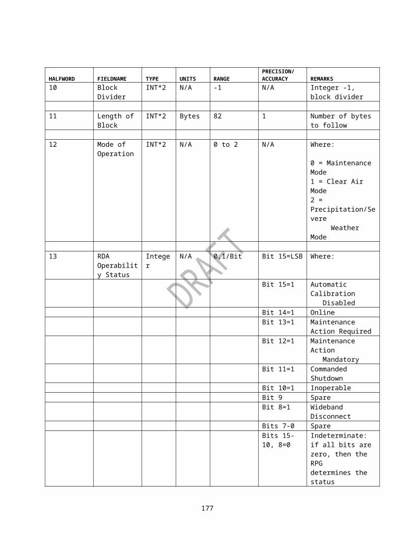
PRODUCT CODE
PRODUCT MNEMONIC ELEVATION
MIN SIZE(Bytes)
MAX SIZE(Bytes)
AVERAGE SIZE(Bytes)
MEDIAN SIZE(Bytes)
27 V 1.3 15814 19796 17901 1824627 V 1.8 14758 18038 16853 1714628 SW 0.5 41934 45846 43111 4296528 SW 0.9 33398 45846 39751 4146328 SW 1.3 27394 40992 34293 3469128 SW 1.8 26558 35890 30736 3153429 SW 0.5 33158 42384 36340 3600929 SW 0.9 26630 42384 32991 3336829 SW 1.3 23024 34350 27821 2782929 SW 1.8 21692 27626 24309 2482030 SW 0.5 23708 27834 25188 2501730 SW 0.9 19952 27834 23347 2380830 SW 1.3 18374 24248 20763 2084230 SW 1.8 17526 20768 19051 1938231 USP 280 376 283 28032 DHR 85716 85716 85716 8571633 HSR 12012 17660 15034 1532035 CR 25204 28052 26587 2668836 CR 7570 9584 8863 889137 CR 29696 33646 31438 3153038 CR 8298 10276 9526 965541 ET 1866 1998 1936 193648 VWP 5578 11200 9097 943656 SRM 0.5 19522 22448 20705 2043856 SRM 0.9 16556 22448 19376 1958856 SRM 1.3 15882 19588 17656 1762656 SRM 1.8 14678 17892 16566 1677457 VIL 1506 1684 1583 157358 STI 4550 10940 8981 930959 HI 5594 8914 7386 694260 M 3400 5450 4342 420561 TVS 2112 2928 2384 211262 SS 5758 9850 8355 830263 LRA 1744 1850 1789 178464 LRA 1684 1836 1755 174765 LRM 2544 2992 2751 273866 LRM 1970 2150 2083 209267 APR 2196 2506 2338 234374 RCM 1800 2010 1919 194078 OHP 5734 11064 8020 573479 THP 5816 5816 5816 581680 STP 8940 10490 9750 979481 DPA 2592 8316 5036 259282 SPD 2834 2834 2834 283484 VAD 6444 7070 6759 674289 LRA 1524 1648 1589 159190 LRM 1810 1994 1921 193493 DBV 0.5 43582 44070 43948 4394893 DBV 0.9 43582 44070 43950 4394893 DBV 1.3 42362 44070 43624 43460
B-12

PRODUCT CODE
PRODUCT MNEMONIC ELEVATION
MIN SIZE(Bytes)
MAX SIZE(Bytes)
AVERAGE SIZE(Bytes)
MEDIAN SIZE(Bytes)
93 DBV 1.8 42606 44070 43830 4394893 DBV 2.4 43704 44314 43840 4382694 DR 0.5 168376 168376 168376 16837694 DR 0.9 167910 168376 168367 16837694 DR 1.3 148238 168376 160095 16791094 DR 1.8 133782 138390 137637 13800695 CRE 21324 23260 22464 2247096 CRE 7176 9248 8437 842697 CRE 23576 25416 24651 2470998 CRE 7696 9786 8944 893399 DV 0.5 329806 333510 332584 33258499 DV 0.9 329806 333510 332601 33258499 DV 1.3 320546 333510 330126 32888099 DV 1.8 322398 333510 331695 332584132 CLR 0.5 27318 32188 29678 29818132 CLR 0.9 25394 32188 28400 28330132 CLR 1.3 20480 29256 24734 24823132 CLR 1.8 19978 22830 21673 21972133 CLD 0.5 26450 30698 28209 28172133 CLD 0.9 23532 30698 26660 26490133 CLD 1.3 21860 27762 24314 24223133 CLD 1.8 21214 24406 22660 23022134 DVL 10149 16880 13274 12788135 EET 11061 12394 11968 12042136 SO 42247 114620 78433 78433137 ULR 17190 21468 20033 20220138 DSP 44676 44676 44676 44676139 MRU 0.5 120 3622 2501 2858139 MRU 0.9 120 3704 2565 2863139 MRU 1.3 828 3786 2686 2868139 MRU 1.8 992 3786 2797 2898139 MRU 2.4 992 3848 2884 2950139 MRU 3.1 992 3900 3040 3152139 MRU 4.0 992 4052 3162 3266139 MRU 5.1 1982 4086 3326 3522139 MRU 6.4 1982 4168 3343 3535139 MRU 8.0 1982 4172 3395 3618139 MRU 10.0 1982 4172 3396 3618139 MRU 12.5 1982 4172 3396 3618139 MRU 15.6 1982 4172 3396 3618139 MRU 19.5 1816 3970 2834 2908141 MD 136 1890 1347 1562143 TRU 0.5 120 1454 564 120143 TRU 0.9 120 1454 564 120143 TRU 1.3 120 1454 564 120143 TRU 1.8 120 1454 581 120143 TRU 2.4 120 1558 688 120143 TRU 3.1 120 1558 739 120143 TRU 4.0 120 1558 764 120143 TRU 5.1 120 1558 846 1454
B-13

PRODUCT CODE
PRODUCT MNEMONIC ELEVATION
MIN SIZE(Bytes)
MAX SIZE(Bytes)
AVERAGE SIZE(Bytes)
MEDIAN SIZE(Bytes)
143 TRU 6.4 120 1558 846 1454143 TRU 8.0 120 1558 846 1454143 TRU 10.0 120 1558 846 1454143 TRU 12.5 120 1558 846 1454143 TRU 15.6 120 1558 846 1454143 TRU 19.5 120 1454 564 120144 OSW145 OSD146 SSW147 SSD150 USW151 USD
B-14

Table XIV. VCP 121 Product Size
PRODUCT CODE
PRODUCT MNEMONIC ELEVATION
MIN SIZE(Bytes)
MAX SIZE(Bytes)
AVERAGE SIZE(Bytes)
MEDIAN SIZE(Bytes)
16 R 0.5 19000 21078 20347 2057216 R 1.5 14868 16966 15787 1579416 R 2.4 13812 15806 14530 1424616 R 3.3 12804 14232 13271 1310816 R 4.3 11138 12576 11524 1128617 R 0.5 16200 17862 17235 1735217 R 1.5 12102 13690 12716 1268017 R 2.4 10562 11946 10983 1078217 R 3.3 9130 10046 9439 932918 R 0.5 10828 11984 11454 1145418 R 1.5 8068 9328 8568 845218 R 2.4 7136 8242 7527 739918 R 3.3 6430 7320 6743 664719 R 0.5 29606 31364 30437 3038919 R 1.5 21412 25180 22656 2245619 R 2.4 19350 22626 20322 2017519 R 3.3 16830 19332 17704 1758719 R 4.3 14052 16238 14678 1462920 R 0.5 22930 24272 23478 2347420 R 1.5 15986 18486 16671 1648320 R 2.4 13674 15722 14248 1413720 R 3.3 11522 13078 12087 1204721 R 0.5 14824 15526 15137 1508421 R 1.5 10556 12000 11076 1096421 R 2.4 9042 10424 9481 929221 R 3.3 7944 8986 8345 825722 V 0.5 35428 37400 36741 3696622 V 1.5 37930 43412 41496 4237822 V 2.4 37478 44076 41640 4231622 V 3.3 32110 36538 35167 3564723 V 0.5 33194 36608 35389 3583423 V 1.5 34302 38874 37267 3801423 V 2.4 29684 32268 31129 3135823 V 3.3 26036 27300 26792 2686724 V 0.5 28486 34022 31882 3209624 V 1.5 27138 29298 28559 2872024 V 2.4 23584 25044 24418 2445424 V 3.3 20454 21392 20844 2078625 V 0.5 30218 34504 32270 3262625 V 1.5 33698 37098 35396 3530625 V 2.4 34930 39890 37855 3785025 V 3.3 29874 33892 32511 3266625 V 4.3 22224 24418 23863 2402426 V 0.5 31330 32690 32244 3233826 V 1.5 30868 33680 32468 3277826 V 2.4 27166 29544 28513 2866426 V 3.3 23366 25192 24494 2463827 V 0.5 26180 28324 27324 2747527 V 1.5 23322 25192 24500 24458
B-15

PRODUCT CODE
PRODUCT MNEMONIC ELEVATION
MIN SIZE(Bytes)
MAX SIZE(Bytes)
AVERAGE SIZE(Bytes)
MEDIAN SIZE(Bytes)
27 V 2.4 21488 22894 22110 2210827 V 3.3 18848 19862 19283 1926927 V 4.3 15842 16316 16062 1604528 SW 0.5 47334 49068 48380 4856628 SW 1.5 50052 51760 51040 5109128 SW 2.4 46296 50662 49232 4949428 SW 3.3 39916 42890 41781 4183429 SW 0.5 46510 48272 47474 4754429 SW 1.5 42784 44180 43440 4348429 SW 2.4 35054 36218 35478 3536629 SW 3.3 29676 30994 30313 3030930 SW 0.5 37188 39302 38642 3879830 SW 1.5 31842 32788 32388 3239530 SW 2.4 26792 28284 27515 2740430 SW 3.3 22624 24240 23223 2306031 USP 280 10268 2390 42432 DHR 85716 85716 85716 8571633 HSR 28506 30548 29206 2921835 CR 35338 40224 39068 3971236 CR 8064 12580 12136 1248237 CR 50212 55822 54019 5444838 CR 10296 14968 14547 1464441 ET 2744 3274 2933 285742 M 2112 2798 2472 255248 VWP 9218 10388 9516 945350 RCS 636 1614 1121 117951 VCS 1132 1594 1303 122155 SRR 2122 2796 2443 236956 SRM 0.5 24536 30380 28649 2891156 SRM 1.5 22184 26874 26167 2634856 SRM 2.4 20340 23852 23072 2316756 SRM 3.3 17870 20710 19572 1962656 SRM 4.3 15208 17222 16324 1634357 VIL 2128 2608 2278 220858 STI 10438 18062 14424 1408059 HI 10962 11700 11231 1120461 TVS 2112 2112 2112 211262 SS 10840 16580 13560 1341663 LRA 3228 3476 3329 333464 LRA 2574 2786 2671 267865 LRM 3924 4564 4191 410766 LRM 2684 3154 2926 293067 APR 3792 4348 4030 397573 UAM 782 4066 975 97574 RCM 2990 3200 3057 306078 OHP 5734 13600 12359 1262979 THP 5816 12278 8476 1012280 STP 15394 17308 16478 1648681 DPA 2592 14418 11339 1262882 SPD 2834 2834 2834 2834
B-16

PRODUCT CODE
PRODUCT MNEMONIC ELEVATION
MIN SIZE(Bytes)
MAX SIZE(Bytes)
AVERAGE SIZE(Bytes)
MEDIAN SIZE(Bytes)
84 VAD 1948 6924 5265 661689 LRA 1860 1980 1925 190690 LRM 2312 2434 2379 238393 DBV 0.5 43338 43338 43338 4333893 DBV 1.5 43338 43338 43338 4333893 DBV 2.4 43338 43338 43338 4333893 DBV 3.3 36462 36462 36462 3646293 DBV 4.3 28710 28710 28710 2871094 DR 0.5 166046 166046 166046 16604694 DR 1.5 146110 146520 146141 14611094 DR 2.4 120510 120510 120510 12051094 DR 3.3 101966 101966 101966 10196694 DR 4.3 85830 85830 85830 8583095 CRE 29602 34454 33637 3393096 CRE 7762 12250 11819 1215897 CRE 38892 44804 43287 4339298 CRE 9740 14418 13898 1421099 DV 0.5 327954 327954 327954 32795499 DV 1.5 327954 327954 327954 32795499 DV 2.4 327954 327954 327954 32795499 DV 3.3 329806 329806 329806 32980699 DV 4.3 330732 330732 330732 330732132 CLR 0.5 38556 39948 39126 39031132 CLR 1.5 33508 35584 34302 34254132 CLR 2.4 28910 31358 29713 29489132 CLR 3.3 25222 27538 25898 25674133 CLD 0.5 40872 42364 41705 41718133 CLD 1.5 36092 37724 36993 37047133 CLD 2.4 31362 33842 32195 31942133 CLD 3.3 27052 29594 27671 27296134 DVL 37074 43265 38816 37963135 EET 25329 28548 26031 25667136 SO 30561 67536 53762 63190137 ULR 14198 27482 19552 18898138 DSP 44676 44676 44676 44676139 MRU 0.5 120 1402 980 1156139 MRU 1.5 120 1402 1014 1156139 MRU 2.4 120 2224 1227 1279139 MRU 3.3 120 2224 1234 1279139 MRU 4.3 120 2224 1256 1279139 MRU 6.0 120 2224 1268 1320139 MRU 9.9 120 2224 1268 1320139 MRU 14.6 120 2224 1268 1320139 MRU 19.5 120 1402 1008 1156141 MD 136 136 136 136143 TRU 0.5 120 1454 171 120143 TRU 1.5 120 1454 171 120143 TRU 2.4 120 1454 171 120143 TRU 3.3 120 1454 171 120143 TRU 4.3 120 1454 171 120
B-17

PRODUCT CODE
PRODUCT MNEMONIC ELEVATION
MIN SIZE(Bytes)
MAX SIZE(Bytes)
AVERAGE SIZE(Bytes)
MEDIAN SIZE(Bytes)
143 TRU 6.0 120 1454 171 120143 TRU 9.9 120 1454 171 120143 TRU 14.6 120 1454 171 120143 TRU 19.5 120 120 120 120144 OSW145 OSD146 SSW147 SSD150 USW151 USD152 ASP TBD TBD TBD TBD
B-18

Table XV. X-25 Bandwidth Estimation for an Example Class 1 User RPS List (See Note 1)
ProductCode
ProductName
Elevation EstimatedSize (bytes)
WithX.25Overhead(Note 2)
Total With SatcomX.25Overhead(Note 3)
SatcomTotal
2 GSM 124 8 132 8 13219 R .5 29250 1832 31082 784 3003419 R 1.5 29250 1832 31082 784 3003419 R 2.4 29250 1832 31082 784 3003419 R 3.4 29250 1832 31082 784 3003426 V .5 24250 1520 25770 704 2495427 V 1.5 21750 1360 23110 664 2241427 V 3.4 21750 1360 23110 664 2241427 V 6.2 21750 1360 23110 664 2241427 V 21750 1360 23110 664 2241433 HSR 28250 1768 30018 768 2901837 CR 45250 2832 48082 1352 4660256 SRM .5 20750 1304 22054 648 2139856 SRM 1.5 20750 1304 22054 648 2139856 SRM 2.4 20750 1304 22054 648 2139856 SRM 3.4 20750 1304 22054 648 2139856 SRM 4.3 20750 1304 22054 648 2139856 SRM 7.5 20750 1304 22054 648 2139857 VIL 2750 176 2926 48 279858 STI 19500 1224 20724 472 1997259 HI 11750 736 12486 344 1209460 M 5750 360 6110 96 5846Total Bytes Transferred per 5 Minute Scan 495872 -Total Bits Transferred in 300 Second Scan 3966976 -Bandwidth Required in Bits per second (bps) 13223.25 -Total Bytes Transferred per 5 Minute Scan 480104Total Bits Transferred in 300 Second Scan 3840832Bandwidth Required in Bits per second (bps) 12802.77Note 1: Assumption is VCP 11, which uses a 5 minute (300 sec) scan strategy. This example calculation would be typical of estimating bandwidth for a Class 1 user. The Class 1 user has a dedicated connection and should send a Routine Product Set (RPS) list request dependent upon VCP or precipitation detection. This example does not account for the initial connection data exchanges, e.g. Product codes 6, 7, and 8 or Class 1 (e.g. PUP) status exchanges. Nor does the example include overhead attributed to protocol acknowledgements.Note 2: If product size is < 10240 bytes, then data packet overhead is calculated as follows:
Let P = Product Size, X.25/LAPB/Flag Overhead = 8 bytes [dividend of (P ÷ 128) + 1] x 8 bytes
If product size is > 10240 bytes or multiple of 10240 bytes, then data packet overhead is calculated:
80 x [dividend of (P ÷ 10240)] x [((Remainder of (P ÷10240)) ÷ 128) + 1] x 8 bytesNote 3: If product size is < 10240 bytes, then data packet overhead is calculated as follows:
B-19
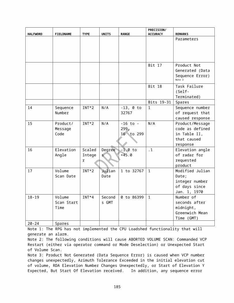
Let P = Product Size, X.25/LAPB/Flag Overhead = 8 bytes [dividend of (P ÷ 512) + 1] x 8 bytes
If product size is > 10240 bytes or multiple of 10240 bytes, then data packet overhead is calculated:
40 x [dividend of (P ÷ 10240)] x [((Remainder of (P ÷ 10240)) ÷ 512) + 1] x 8 bytesBandwidth Estimation Example The estimated transfer rates for an example Class 1 user RPS list are tabulated below. The estimates only include routine products and not additional one time request (OTR). As indicated in Note 1, this example is for the worse case coverage pattern. VCP 11 is a 14 elevation scan strategy completed in 5 minutes (300 seconds). Omitted in estimates is the additional payload of protocol acknowledgements. The estimate does include calculation for both the default NEXRAD X.25 configuration of 128 byte data packets and the communications option packet size of 512 bytes for each data packet. Reference section 7.1 Ten Kilobyte Segmentation of 2620040, ICD for RPG X.25 Protocol for more detail on the 10240 byte product segmentation. The X.25/LAPB overhead consists of: 3 bytes for X.25 + 4 bytes for LAPB + 1 byte for the inter-frame flag.
B-20

Table XVI. - VCP 211 Product Sizes
PRODUCT CODE PRODUCT MNEMONIC
ELEVATION MIN SIZE (Bytes)
MAX SIZE (Bytes)
AVERAGE SIZE (Bytes)
MEDIAN SIZE (Bytes)
39 R 1.5 13340 16328 15428 1582839 R 2.4 13686 16520 15456 1569839 R 3.3 13236 16942 15373 1559639 R 4.3 12502 16450 14927 1529628 R 0.5 14332 15928 15017 1512128 R 1.5 10690 12322 11658 1188528 R 2.4 10482 12474 11688 1189728 R 3.3 10310 12468 11684 1195429 R 4.3 10194 12096 11424 1165039 R 0.5 15338 16780 16018 1606839 R 1.5 11020 12736 12148 1230239 R 2.4 9924 11486 10920 1102437 R 3.3 8890 10806 10106 1019837 R 4.3 7854 9980 9189 938228 R 0.5 12716 13950 13391 1347728 R 1.5 9356 10304 9878 993728 R 2.4 8242 9132 8746 882328 R 3.3 7332 8354 7961 807729 R 4.3 6522 7676 7225 735628 R 0.5 9892 10864 10387 1041128 R 1.5 7508 8326 7969 803428 R 2.4 6694 7686 7317 739328 R 3.3 6336 7410 6949 706729 R 4.3 5638 6860 6395 650428 R 0.5 8484 9310 8890 888228 R 1.5 6566 7086 6806 680928 R 2.4 5812 6424 6153 621228 R 3.3 5374 5950 5696 574929 R 4.3 4786 5522 5232 528439 SW 0.5 39028 47066 41744 4097837 SW 1.5 22946 33990 28308 2804637 SW 2.4 14076 21188 17735 1775837 SW 3.3 12980 18858 15716 1539837 SW 4.3 13062 17818 14913 1433828 SW 0.5 35404 42236 38301 3807728 SW 1.5 18430 25802 21467 2103028 SW 2.4 13584 19014 15584 1522329 SW 3.3 13402 17810 15204 1494829 SW 4.3 13814 17298 15073 1490639 SW 0.5 25088 29366 26522 2565439 SW 1.5 15972 20440 18091 1806839 SW 2.4 12430 15966 14127 1393239 SW 3.3 12154 14942 13482 1344237 SW 4.3 11988 13928 12789 1275839 V 0.5 28664 35648 31199 3064237 V 1.5 19884 25530 22480 2210437 V 2.4 15996 20588 17998 1794437 V 3.3 15498 19208 16971 1653437 V 4.3 13158 18368 16450 16284
B-21

PRODUCT CODE PRODUCT MNEMONIC
ELEVATION MIN SIZE (Bytes)
MAX SIZE (Bytes)
AVERAGE SIZE (Bytes)
MEDIAN SIZE (Bytes)
28 V 0.5 27228 38210 31015 2936128 V 1.5 19306 26684 22335 2241828 V 2.4 15836 19640 17648 1743029 V 3.3 15914 18104 16764 1661829 V 4.3 13080 17156 16274 1624828 V 0.5 26238 31782 28561 2817028 V 1.5 16748 21198 18317 1789528 V 2.4 14712 17730 15888 1552729 V 3.3 15040 17798 16055 1573029 V 4.3 15082 17272 16155 1618828 V 0.5 25982 35150 29308 2794028 V 1.5 17126 22718 19210 1894828 V 2.4 15032 17658 16228 1613729 V 3.3 15226 17084 16048 1583829 V 4.3 15344 17416 16387 1641239 V 0.5 20354 24284 21727 2118439 V 1.5 15326 18000 16374 1623839 V 2.4 13156 15626 14229 1402839 V 3.3 13258 14982 14003 1382439 V 4.3 12134 14190 13558 1362839 V 0.5 20606 26248 22318 2144037 V 1.5 15358 19172 16750 1669237 V 2.4 13162 15510 14152 1414237 V 3.3 13078 14560 13700 1372237 V 4.3 12088 13876 13349 1333637 CR 31432 34754 33057 3271335 CR 24428 26228 25312 2517438 CR 6732 10084 7184 704136 CR 6052
6196 6136 6140
41 ET 2080 2234
2161 2171
59 HI 3560 8916
5617 5607
48 VSP 6742 11546 10897 1145863 LRA 2142
2364 2293 2310
64 LRA 2046 2230
2118 2114
65 LRM 2744 2960
2876 2883
66 LRM 2236 2454
2345 2351
60 M 2112 2388
2136 2112
67 APR 2698 2922
2829 2839
62 SS 4926 9710
6959 6852
58 STI 3466 11240 6561 611331 USP 520 16428 6230 520
B-22

PRODUCT CODE PRODUCT MNEMONIC
ELEVATION MIN SIZE (Bytes)
MAX SIZE (Bytes)
AVERAGE SIZE (Bytes)
MEDIAN SIZE (Bytes)
32 DHR 29653 32666 30982 3074233 HSR 18122 19608 18609 1849039 SRM 0.5 19346 24414 21628 2129039 SRM 1.5 15702 18484 16570 1640239 SRM 2.4 13250 16438 14595 1434639 SRM 3.3 13420 15594 14374 1426239 SRM 4.3 12696 15092 14044 1409228 SRR 0.5 11214 15692 12913 1237428 SRR 1.5 8936 12224 9881 960228 SRR 2.4 7938 10270 8859 859529 SRR 3.3 7602
9696 8497 8296
29 SRR 4.3 6856 9014
8296 8392
61 TVS 2112 2112
2112 2112
51 VCS 1628 1718
1670 1670
50 RCS 1490 1556
1526 1530
57 VIL 1670 1868
1783 1780
28 DBV 0.5 44070 44070 44070 4407028 DBV 1.5 44070 44070 44070 4407028 DBV 2.4 44070 44070 44070 4407029 DBV 3.3 36870 36870 36870 3687029 DBV 4.3 28950 28950 28950 2895032 DR 0.5 31931 35059 33479 3372832 DR 1.5 22152 24610 23090 2296733 DR 2.4 18843 21128 19944 1981533 DR 3.3 19446 20637 20139 2009533 DR 4.3 17449 20041 19212 1944232 DV 0.5 77061 87291 82648 8313833 DV 1.5 52250 60582 55679 5536233 DV 2.4 40554 49827 44335 4386633 DV 3.3 45061 47971 46152 4611333 DV 4.3 42894 47465 44823 4463478 OHP 5734 11070 9075 1041479 THP 5816
9070 6900 5816
80 STP 8448 11010 10255 1031481 DPA 2592
9342 6914 8614
82 SPD 2834 2834
2834 2834
84 VAD 5396 6846 6094 611285 RCS 1488
1540 1518 1522
86 VCS 1632 1712
1672 1676
89 LRA 1520 1618 1561 1566
B-23

PRODUCT CODE PRODUCT MNEMONIC
ELEVATION MIN SIZE (Bytes)
MAX SIZE (Bytes)
AVERAGE SIZE (Bytes)
MEDIAN SIZE (Bytes)
90 LRM 1848 2096
2005 2010
97 CRE 30854 32906 31885 3199895 CRE 24100 25840 24784 2466698 CRE 6822
8718 7039 6974
96 CRE 5986 7800
6157 6096
74 RCM 1940 2290
2173 2220
39 CLR 0.5 30326 33624 31654 3107037 CLR 1.5 24974 26820 25647 2538837 CLR 2.4 22610 24240 23366 2321037 CLR 3.3 22774 23564 23233 2324437 CLR 4.3 21616 23152 22458 2241039 CLD 0.5 30764 33752 32226 3179837 CLD 1.5 24166 26242 25168 2507037 CLD 2.4 21450 24170 22445 2232637 CLD 3.3 22402 23534 22820 2277237 CLD 4.3 21818 23308 22510 22508134 DVL 23572 26483 25262 25340135 EET 10162 12049 11223 11422136 SO 10578
2108860
107170 106869
137 ULR 21048 21870 21402 21338138 DSP 44628 44628 44628 4462839 MRU 0.5 120 828 174 12039 MRU 1.5 120 828 192 12039 MRU 2.4 120 828 192 12039 MRU 3.3 120 828 192 12039 MRU 4.3 120 992 233 120140 GFM 248
2580 993 248
141 MD 120 120 120 12039 TRU 0.5 120 120 120 12039 TRU 1.5 120 120 120 12039 TRU 2.4 120 120 120 12039 TRU 3.3 120 120 120 12039 TRU 4.3 120 120 120 120144 OSW 2836 21556 15304 20462145 OSD 2836 24756 16519 21854146 SSW 2836 17304 15065 15710147 SSD 2836 16850 14692 1523632 DMD 0.5 736
1841 1000 1052
33 DMD 1.5 748 2291
1144 1064
33 DMD 2.4 760 2454
1344 1403
33 DMD 3.3 772 2427
1381 1427
B-24

PRODUCT CODE PRODUCT MNEMONIC
ELEVATION MIN SIZE (Bytes)
MAX SIZE (Bytes)
AVERAGE SIZE (Bytes)
MEDIAN SIZE (Bytes)
33 DMD 4.3 780 2430
1377 1428
150 USW 3082 3082
3082 3082
151 USD 3082 3082
3082 3082
B-25

APPENDIX D. PRODUCT DATA COMPRESSION USING BZIP2
In order to decompress products having been compressed using bzip2, the libbzip2 library, version 1.0.1 or higher, is required. The source code can be found at the official home page (URL): http://sources.redhat.com/bzip2. This web site contains complete instructions on building the libbzip2 library on a wide range of computer architectures and operating systems. Detailed documentation of the various library functions is also provided.Within libbzip2, the library function that should be used to decompress the data is:
BZ2_bzBuffToBuffDecompress( char *dest, unsigned intdestLen, char *source, unsigned intsourceLen, intsmall, int verbosity). The destination buffer “dest” holds the decompressed product. The destination buffer size “destLen” must be at least as large as the sum of the Message Header block, Product Description block and the compressed product data size given by the Product Dependent Parameters (see Table V). The source “source” points to the compressed product data immediately following the Product Description block. The source length “sourceLen” is the total product size (defined in the Message Header block), less the size of the Message Header and Product Description blocks. Depending on the architecture, “small” can either be 0 (normal case) or non-zero. By specifying a non-zero value for “small”, the library requires less memory utilization at the expense of increased decompression time. The verbosity level can take on any value from 0 to 4 inclusive with higher values denoting greater verbosity. After the product is decompressed, the products Message Header and Product Description blocks can be prepended to the decompressed product data.
D-1

APPENDIX E. GENERIC PRODUCT FORMAT
The Generic Product Format is designed to be a flexible, platform independent data format wherein the information describing the data is contained in the data itself. Information for each product that typically has been included in this interface control document such as the parameter’s definition, type, range, precision and scaling, is encoded in the data structures defined in this appendix.The first item within the deserialized data will be the Product Description data structure (for packet 28 data) or the External Data Description data structure (for packet 29 data). The Product Description data structure is defined in Figure E-1. The External Data Description data structure is defined in Figure E-1b. Additional product data is determined by the values of “Parameter List” and “Component List”. The Parameter List is defined in Figure E-2. The possible Component List data structures are defined in Figures E-3 through E-11.
The following conventions will be used for describing data structure element types:Byte/Char One byte (8 bits)INT*2 2 byte, signed integer dataINT*4 4 byte, signed integer dataUINT*4 4 byte, unsigned integer dataREAL*4 4 byte, floating point data adhering to IEEE-754-1985 standardString NULL (0) terminated array of ASCII coded characters, each character occupying 1
bytePointer Contains the address of a data item. Size is architecture dependent.
NAMEDESCRIPTIONCODETYPEGENERATION TIMERADAR NAMERADAR LATITUDERADAR LONGITUDERADAR HEIGHTVOLUME SCAN START TIMEELEVATION SCAN START TIMEELEVATION ANGLEVOLUME SCAN NUMBEROPERATIONAL MODEVOLUME COVERAGE PATTERNELEVATION NUMBERSPARESPARENUMBER OF PARAMETERSPARAMETER LISTNUMBER OF COMPONENTSCOMPONENT LIST
Figure E-1. Product Description Data Structure (Sheet 1)
E-1

FIELD NAME TYPE UNITS RANGE PRECISION/ACCURACY
REMARKS
Name String N/A N/A N/A Product name
Description String N/A N/A N/A Product description (may contain version information)
Code INT*4 N/A See Table II N/A Product code
Type INT*4 N/A 1 to 7 1/1 1=Volume, 2=Elevation, 3=Time,4=On Demand,5=On Request, 6=Radial, 7=External
Generation Time
UINT*4 Seconds 0 to 4294967295
1/0.5 Product generation time. See Note 1.
Radar Name String N/A N/A N/A Null or empty string indicates the radar name is not applicable
Radar Latitude
REAL*4 Degrees -90.0 to +90.0
N/A Only applicable if radar name specified.
Radar Longitude
REAL*4 Degrees -180.0 to +180.0
N/A Only applicable if radar name specified.
Radar Height
REAL*4 Meters 30 to 3350 N/A Meters above mean sea level.
Volume Scan Start Time
UINT*4 Seconds 0 to 4294967295
1/0.5 Volume scan start time. See Note 1.
Elevation Scan Start Time
UINT*4 Seconds 0 to 4294967295
1/0.5 Used only if type is equal to 2. See Note 1.
Elevation Angle
REAL*4 Degrees -1.0 to +45.0
N/A Angle of elevation scan
E-2

FIELD NAME TYPE UNITS RANGE PRECISION/ACCURACY
REMARKS
Volume Scan Number
INT*4 N/A 1 to 80 N/A Counter, recycles to 1 after 80 volume scans.
Operational Mode
INT*2 N/A 1 to 3 N/A 1=Test,2=Clear Air,3=Precipitation
Volume Coverage Pattern
INT*2 N/A 0 to 999 N/A Volume coverage pattern (VCP) number
Elevation Number
INT*2 N/A 1 to 20 N/A Elevation number within the VCP. Only used if type is equal to 2.
Spare INT*2 N/A N/A N/A Spare (reserved for future compression type)
Spare INT*4 N/A N/A N/A Spare (reserved for future decompressed size)
Number of Parameters
INT*4 N/A 0 to 1000 N/A Number of product specific parameters
Parameter List
Pointer to Structure
N/A N/A N/A See Note 2
Number of Components
INT*4 N/A 0 to 1000 N/A Number of product specific components
Component List
Pointer to Structure
N/A N/A N/A See Note 3
Figure E-1. Product Description Data Structure (Sheet 2)
Note 1. Specified in number of seconds elapsed since midnight GMT January 1, 1970 (Unix Time).Note 2. Product Parameter data structure defined in Figure E-2.Note 3. When the product contains multiple detected events, this is an array of pointers to Event Component data structures (see Figure E-10). A product can have any number of events. If there is only one event, this is an array of pointers, each of which points to one of the following product component structure types: Radial Component (Figure E-3), Grid Component (Figure E-5), Area Component (Figure E-6), Text Component (Figure E-8), or
E-3

Table Component (Figure E-9). A product can have any number of components of mixed types.
NAMEDESCRIPTIONCODETYPEGENERATION TIMESPARE (MSW)SPARE (LSW)SPARE (MSW)SPARE (LSW)SPARE (MSW)SPARE (LSW)SPARE (MSW)SPARE (LSW)NUMBER OF PARAMETERSPARAMETER LISTNUMBER OF COMPONENTSCOMPONENT LIST
Figure E-1b. External Data Description Data Structure (Sheet 1)
E-4

FIELD NAME TYPE UNITS RANGE PRECISION/ACCURACY
REMARKS
Name String N/A N/A N/A Product nameDescription String N/A N/A N/A Product
description (may contain version information)
Code INT*4 N/A See Table II
N/A Product code
Type INT*4 N/A 7 1/1 Product type = External
Generation Time
UINT*4 Seconds 0 to 4294967295
1/0.5 Product generation time. See Note 1.
Spare INT*4 N/A N/A N/A SpareSpare INT*4 N/A N/A N/A SpareSpare INT*2 N/A N/A N/A SpareSpare INT*2 N/A N/A N/A Spare
(reserved for future compression type)
Spare INT*4 N/A N/A N/A Spare (reserved for future decompressed size)
Number of Parameters
INT*4 N/A 0 to 1000 N/A Number of product specific parameters
Parameter List Pointer to Structure
N/A N/A N/A See Note 2
Number of Components
INT*4 N/A 0 to 1000 N/A Number of product specific components
Component List
Pointer to Structure
N/A N/A N/A See Note 3
Figure E-1b. External Data Description Data Structure (Sheet 2) Note 1. Specified in number of seconds elapsed since midnight GMT January 1, 1970 (Unix Time).Note 2. Product Parameter data structure defined in Figure E-2.Note 3. When the product contains multiple detected events, this is an array of pointers to Event Component data structures (see Figure E-10). A product can have any number of events. If there is only one event, this is an array of pointers, each of which points to one of the following product component structure types: Radial Component (Figure E-3), Grid Component (Figure E-5), Area Component (Figure E-6), Text Component (Figure E-8), or Table Component (Figure E-9). A product can have any number of components of mixed types.
E-5

PARAMETER IDPARAMETER ATTRIBUTES
Figure E-2. Product Parameter Data Structure (Sheet 1)
FIELD NAME TYPE UNITS RANGE PRECISION/ACCURACY
REMARKS
Parameter ID
String N/A N/A N/A Parameter identifier
Parameter Attributes
String N/A N/A N/A See Notes 1, 2.
Figure E-2. Product Parameter Data Structure (Sheet 2)
Note 1. Format description of the ASCII-text parameter attributes:
1. The attributes are represented by an ASCII string. The string consists of a number of sections terminated by ";", each of which specifies an applicable attribute. ";" after the last section is optional. Each section must be in the form of "attribute name = attribute description" where "attribute name" must be one of the following: "name", "type", "unit", "range", "value", "default", "accuracy", "description", "conversion" and "exception". The attribute name is case-insensitive. That is, for example, "name", "Name" and "NAME" are all valid and identical. "attribute description" is a character string that describes the value of the attribute as explained in the following.2. Attribute description:
"name": The name of the parameter. An example is"name = 2D feature altitude".
"type": One of the following type names: "int", "short", "byte"(4-byte, 2-byte and 1-byte integer respectively), "bit" (1-bit data),"float", "double" (4-byte and 8-byte IEEE floating point numbersrespectively), "string" (ASCII character string), "unit", "ushort" and"ubyte" (unsigned versions of int, short and byte). An example is "type= int". If type is not specified, "int" is assumed. The type name iscase-insensitive.
"unit": The physical unit of the data value. Standard unit names are tobe defined. Examples are "unit = meter" and "unit = percent".
"range": The set of all valid values for the parameter. The range canbe specified with one of the following three formats:
a. Single interval specification defined by "[min, max]" where "min" and "max" are respectively the minimum and maximum values. "[" and "]" can be replaced by "(" and ")" respectively if the boundary is not inclusive. Unlimited boundary is specified by "-". Examples are "range = [1, 2]", "range = (1, 2]", "range = [1., -)", "range = [A, Z]" (character string type), and "range = (-, -)".
b. A list of valid values: { v1, v2, ...}. Examples are "range = {1, 2, 3}" and "range = {reflectivity, velocity, spectrum width}.
c. A named method that checks the range. The method name is enclosed by "<" and ">". The method must be described elsewhere.
E-6

"value" and "default": A value or a list of values separated by ",".Examples are "value = 1", "value = 1.0, 2., 3.0" and "value = Yes, No".
"accuracy": The accuracy of the data. [max_error] is used for theabsolute maximum error and (max_error) for the relative maximum error.
"description": A text description of the data.
"conversion": The way to convert binary data stored externally. Theconversion can be specified with one of the following formats:
a. Format [scale, offset] is used for scale-offset type of conversion: value = data * scale + offset. An example is "conversion = [2., 64.]".
b. Format {valueMap, data1, value1, data2, value2, ...} for data mapping conversions. Where "valueMap" is a reserved key word. "data1", "data2" ... are the data and "value1", "value2" ... are the values to convert to. An example is "conversion = {valueMap, 1, -5., 2, 0., 3, 50., 4, 100.}".
c. Format <method> is used for named conversion method. The method must be described elsewhere. Elements of binary data array are assumed to be stored one after another in the local byte order for types other than "bit" and "string". For type "bit", we assume that the elements are stored in a byte array each of which holds 8 elements. The first bit element is stored in the left-most bit in the bytes. For type "string", elements are null-terminated strings and stored one after another with the null terminator.
"exception": A list of the exceptional data values and their meanings.An example is "exception = 0, below threshold, 1, missing data".Standard vocabulary for describing exceptional values needs to beestablished in the future.
3. When characters ";", "=" and "," are used for formatting purpose, characters "space", "tab" and "line return" surrounding them are insignificant. That is, for example, "name = short", "name=short" and "name =short" are all identical. Non-formatting use of ";" and "," are allowed if no ambiguity is introduced. In case of ambiguity, "\" can be used in front of characters ";" and "," to indicate that they are not interpreted as formatting characters. The part of "Attribute description" is case-sensitive except otherwise specified.
Note 2.Component parameters are either definitive or descriptive. Definitive component parameters are required and predefined. Examples are:
The dimension size (number of grid points) for each dimension.
The location of the origin and the coordinate orientation for certain grids.
For equally spaced grid, the step size for each dimension.
E-7

The altitude of a geo-area if the altitude is relevant.
The definitive component parameters must be predefined so the user of the product can interpret and display the data product-independently.
Descriptive component parameters, on the other hand, provide additional descriptions of the product component. Examples are the data field name, the intensity of the event, the forecast position and so on.
RADIAL COMPONENT TYPE (=1)NUMBER OF COMPONENT PARAMETERSCOMPONENT PARAMETER LISTNUMBER OF RADIALSRADIAL DATA
Figure E-3. Radial Component Data Structure (Sheet 1)
FIELD NAME TYPE UNITS RANGE PRECISION/ACCURACY
REMARKS
Radial Component Type
INT*4 N/A 1 N/A Radial component type
Description String N/A N/A N/A Component Description
Number of Component Parameters
INT*4 N/A 1 to 1000 N/A Number of component parameters
Component Parameter List
Pointer to Structure
N/A N/A N/A See Figure E-2
Number of Radials
INT*4 N/A 0 to 800 N/A Number of radials in a radar elevation sweep
Radial Data Pointer to Structure
N/A N/A N/A See Figure E-4
Figure E-3. Radial Component Data Structure (Sheet 2)
AZIMUTHWIDTHBIN SIZERANGE TO FIRST BINBIN VALUES
Figure E-4. Radial Information Data Structure (Sheet 1)
FIELD NAME TYPE UNITS RANGE PRECISION/ACCURACY
REMARKS
Azimuth REAL*4 Degrees 0.0 to 360.0 N/A Azimuth of the leading edge of the radial
Width REAL*4 Degrees 0.0 to 2.0 N/A Radial width or
E-8

separationBin Size REAL*4 Meters 0.0 to
1000.0N/A Range
extent of each bin
Range to First Bin
REAL*4 Meters 1000.0 to 460000.0
N/A Range to the center of the first bin
Bin Values Structure N/A N/A N/A See Figure E-11
Figure E-4. Radial Information Data Structure (Sheet 2)
GRID COMPONENT TYPE (=2)NUMBER OF DIMENSIONSDIMENSIONSGRID TYPENUMBER OF COMPONENT PARAMETERSCOMPONENT PARAMETER LISTGRID DATA
Figure E-5. Grid Component Data Structure (Sheet 1)
E-9

FIELD NAME TYPE UNITS RANGE PRECISION/ACCURACY
REMARKS
Grid Component Type
INT*4 N/A 2 N/A Grid component type
Number of Dimensions
INT*4 N/A 1 to 4 N/A Number of grid dimensions
Dimensions Pointer to INT*4
N/A N/A N/A Grid dimensions, ordered from fastest changing to slowest.
Grid Type INT*4 N/A 1 to 4 N/A 1=Array,2=Equally spaced,3=Lat/Lon,4=Polar
Number of Component Parameters
INT*4 N/A 1 to 1000 N/A Number of component parameters
Component Parameter List
Pointer to Structure
N/A N/A N/A See Figure E-2. See Note 1.
Grid Data Structure N/A N/A N/A See Figure E-11.
Figure E-5. Grid Component Data Structure (Sheet 2)
Note 1. Grid origin and dimension sizes are defined by component parameters. For equally spaced dimensions, we use component parameters for specifying the step sizes. For each unequally spaced grid dimension, we use an additional 1-D grid component to specify the grid pointer locations in that dimension.
AREA COMPONENT TYPE (=3)NUMBER OF COMPONENT PARAMETERSCOMPONENT PARAMETER LISTAREA TYPENUMBER OF POINTSLIST OF POINTS
Figure E-6. Area Component Data Structure (Sheet 1)
E-10

FIELD NAME
TYPE UNITS RANGE PRECISION/ACCURACY
REMARKS
Area Component Type
INT*4 N/A 3 N/A Area component type
Number of Component Parameters
INT*4 N/A 1 to 1000 N/A Number of component parameters
Component Parameter List
Pointer to Structure
N/A N/A N/A See Figure E-2
Area Type INT*4 N/A 1 to 131075
N/A 0x00001=Point (Lat/Lon),0x00002=Area (Lat/Lon),0x00003=Polyline (Lat/Lon),0x10001=Point (X/Y),0x10002=Area (X/Y),0x10003=Polyline (X/Y),0x20001=Point (Az/Ran),0x20002=Area (Az/Ran),0x20003=Polyline (Az/Ran)
Number of Points
INT*4 N/A 1 to 10000 N/A Number of data points
List of Points
Pointer to Structure
N/A N/A N/A See Figure E-7a, E-7b, and E-7c.
Figure E-6. Area Component Data Structure (Sheet 2)
LATITUDELONGITUDE
Figure E-7a. Geographic Location Data Structure (Sheet 1)
FIELD NAME TYPE UNITS RANGE PRECISION/ACCURACY
REMARKS
Latitude REAL*4 Degrees -90.0 to +90.0
N/A Latitude location of data point
Longitude REAL*4 Degrees -180.0 to +180.0
N/A Longitude location of data point
Figure E-7a. Geographic Location Data Structure (Sheet 2)
X COORDINATEY COORDINATE
Figure E-7b. X/Y Location Data Structure (Sheet 1)
FIELD NAME TYPE UNITS RANGE PRECISION/ REMARKS
E-11

ACCURACYX Coordinate REAL*4 km N/A N/A X-coordinate of data
point (See Note 1)Y Coordinate REAL*4 km N/A N/A Y-coordinate of data
point (See Note 1)Figure E-7b. X/Y Location Data Structure (Sheet 2)
Note 1. The default unit for the X/Y location structure is kilometers (km). If a different unit is required, it must be specified in the component parameters.
AZIMUTHRANGE
Figure E-7c. Az/Ran Location Data Structure (Sheet 1)
FIELD NAME TYPE UNITS RANGE PRECISION/ACCURACY
REMARKS
Azimuth REAL*4 Degrees N/A N/A Azimuth of data pointRange REAL*4 km N/A N/A Range of data point
(See Note 1)Figure E-7c. Az/Ran Location Data Structure (Sheet 2)
Note 1. The default unit for range is kilometers. If a different unit is required, it must be specified in the component parameters.
TEXT COMPONENT TYPE (=4)NUMBER OF COMPONENT PARAMETERSCOMPONENT PARAMETER LISTTEXT
Figure E-8. Text Component Data Structure (Sheet 1)
FIELD NAME TYPE UNITS RANGE PRECISION/ACCURACY
REMARKS
Text Component Type
INT*4 N/A 4 N/A Text component type
Number of Component Parameters
INT*4 N/A 1 to 1000 N/A Number of component parameters
Component Parameter List
Pointer to Structure
N/A N/A N/A See Figure E-2
Text String N/A N/A N/A ASCII stringFigure E-8. Text Component Data Structure (Sheet 2)
TABLE COMPONENT TYPE (=5)NUMBER OF COMPONENT PARAMETERSCOMPONENT PARAMETER LISTTITLENUMBER OF COLUMNS
E-12

NUMBER OF ROWSCOLUMN LABELSROW LABELSENTRIES
Figure E-9. Table Component Data Structure (Sheet 1)
FIELD NAME TYPE UNITS RANGE PRECISION/ACCURACY
REMARKS
Table Component Type
INT*4 N/A 5 N/A Table component type
Number of Component Parameters
INT*4 N/A 1 to 1000 N/A Number of component parameters
Component Parameter List
Pointer to Structure
N/A N/A N/A See Figure E-2
Title String N/A N/A N/A ASCII stringNumber of Columns
INT*2 N/A 1 to 32768 N/A Number of columns in table
Number of Rows
INT*2 N/A 1 to 32768 N/A Number of rows in table
Column Labels
Pointer to Structure
N/A N/A N/A See Figure E-12.
Row Labels Pointer to Structure
N/A N/A N/A See Figure E-12.
Entries Structure N/A N/A N/A See Figure E-12.
Figure E-9. Table Component Data Structure (Sheet 2)
EVENT COMPONENT TYPE (=6)NUMBER OF EVENT PARAMETERSEVENT PARAMETER LISTNUMBER OF COMPONENTSCOMPONENT LIST
Figure E-10. Event Component Data Structure (Sheet 1)
FIELD NAME TYPE UNITS RANGE PRECISION/ACCURACY
REMARKS
Event Component Type
INT*4 N/A 6 N/A Event component type
Number of Event Parameters
INT*4 N/A 1 to 10000 N/A Number of event parameters
E-13

Event Parameter List
Pointer to Structure
N/A N/A N/A See Figure E-2.
Number of Components
INT*4 N/A 1 to 1000 N/A Number of components
Component List
Pointer N/A N/A N/A See Note 1.
Figure E-10. Event Component Data Structure (Sheet 2)
Note 1. An array of pointers each of which points to one of the product component structures. An event can have any number of components of mixed types. Possible types are Radial Component (Figure E-3), Grid Component(Figure E-5), Area Component (Figure E-6), Text Component (Figure E-8), and Table Component (Figure E-9).
ATTRIBUTESDATA
Figure E-11. Binary Data Data Structure (Sheet 1)
FIELD NAME TYPE UNITS RANGE PRECISION/ACCURACY
REMARKS
Attributes String N/A N/A N/A See Figure E-2 Note 1. Attribute “type” is required.
Data Pointer N/A N/A N/A See Note 1.Figure E-11. Binary Data Data Structure (Sheet 2)
Note 1. The data is fully described by “Attributes”. The attributes are used to interpret the data. For Grid Component data (see Figure E-5), the gridded data are stored as a 1-dimensional array with the index of the first dimension varying the fastest.
For Table Component data, “Entries” is an “Number of Rows” X “Number of Columns” array with the row index varying the fastest. TEXT STRING
Figure E-12. String Data Structure (Sheet 1)
FIELD NAME TYPE UNITS RANGE PRECISION/ACCURACY
REMARKS
Text String String N/A N/A N/A ASCII coded characters terminated with a null character
Figure E-12. String Data Structure (Sheet 2)
E-14