basic articulator module instructions manual for panadent pch...prosthodontics has changed...
TRANSCRIPT

Introduction
Component Identification
Face-Bow (Ear-Nasion) Instructions
Maxillary Cast Mounting Instructions
Interocclusal Record Instructions • Centric Relation • Protrusive • Left Lateral • Right Lateral
Mandibular Cast Mounting Instructions
Articulator Adjustments (Protrusive)
Articulator Functions
Magna-Split II Instructions
Basic Articulator ModuleInstructions
M Panadent Corporation580 S. Rancho Avenue • Colton, California 92324, USATel: (909) 783-1841 • USA & Canada (800) 368-9777
h 5401
L-BAM REV 25401

L-BAM REV 25401
1. Articulator (Model PCH shown)2. Articulator Support Legs (not shown)3. Pana-Mount ™ Face-bow4. Bio-Esthetic Level Gauge5. Molded Plastic Case6. Mandibular Mounting Stand7. Magna-Split II System (not shown)8. Bite-Tray™ Registration Plates (20)9. Bite-Tab™ Compound Discs (180)
10. Basic Instruction Manual
BASIC SYSTEM COMPONENTS

L-BAM REV 25401
1. Pana-Mount Face-Bow (Frame Assembly)2. Mounting Fixture3. Nasion Relator (22mm)4. Bite-Fork & Stem Assembly (2each)5. Hex Wrench
FACE-BOW COMPONENTS:
i

L-IPSWO REV 1 10/13/08Page
1
Prosthodontics has changed significantly over the years to the point where patient’s acceptance orrequests for complete removable dentures has been replaced with requests to save the natural dentitionwith restorative and fixed prostheses, including implants. The relationship of teeth, TM Joints andneuromuscular system is being increasingly recognized as important factors in fixed prosthodontics aswell as orthodontics. Concurrently, the need for user-friendly articulators that simulate individual patient’scharacteristic jaw movements has increased.
Using a point midway between the lateral and medial condyle pole to represent the path of the condyle,research shows that the condylar movements of one patient are similar in certain aspects to those ofothers. For example, beyond the lateral functional range (3mm from centric relation) contralateral condyles,in the horizontal plane, show similar orbiting paths of about 6-7°. The curvature of protrusive and lateralborder paths in the functional range, in the sagittal plane, are approximately ¾” radii. The lateral borderand protrusive paths of contralateral condyles, in the sagittal plane, are usually identical in the functionalrange (3mm). The paths of ipsilateral condyles are primarily horizontal and/or pivotal in the functionalrange (3mm).
In the lateral functional range (3mm), condylar movement patterns differ primarily in two aspects: (1) theradius curvature of the lateral border path of the contralateral condyle in the horizontal plane and (2) thesteepness of the lateral border and protrusive path in the sagittal plane.
Research shows that under functional loads, patients’ condylar movements on the contralateral side arenot straight paths. The paths curve simultaneously in the three planes of space. Jaw movement studiesalso show that contralateral condylar paths create the major differences between patients’ lateral jawmovements in the functional range (3mm). The ipsilateral condylar paths (Bennett) are primarily horizontaland/or pivotal in the functional range (3mm).
Over the years, attempts have been made to compensate for the curved contralateral paths observedand recorded on patients by various methods. Some manufacturers have incorporated a variablestraight-line “side shift” in their articulator guides (Fig. b). The contralateral condylar element, (Fig. b),does not begin its detrusive movement until after the "side shift" has ended at point “S”. Thus a purehorizontal movement takes place on the articulator. In some instances these horizontal articulatormovements encompass almost the entire occlusal width of the posterior teeth. Negative effects ofhorizontal straight line overcompensating “side shift” articulator movements (Fig. b) include:
(1) Articulators that become awkward to manipulate(2) Unnatural mandibular motion simulation(3) Possibilities of producing low profile (flattened) occlusal surfaces which may overload patients’
temporomandibular joints, teeth, muscles, periodontia, ridges, implants, and prostheses duringfunction.
Compensating curved contralateral articulator paths (Fig. c ) are superior because:(1) Research shows the articulator movements more closely simulate those of the individual patient.(2) They enable dentists, technicians, and students to observe realistic movements of the mandible
as it translates and rotates simultaneously in three planes of space (six degrees of freedom ofmotion).
(3) The articulators are easier to manipulate (user-friendly) during diagnosis as well as constructingartificial occlusal surfaces.
(4) Curved paths help dentists and technicians create better occlusal forms while concurrently
Introduction to the Panadent System

L-IPSWO REV 1 10/13/08Page
2
A functional border path of the contralateral condylar element is represented by the dottedcurved lines in (Figs. a and b), and the solid curved line (Fig. c). The path from CR to B (Fig. a)represents an undercompensating straight line contralateral guide. The solid rectilinear lineCR-S-B (Fig. b) represents an over-compensating straight line, pure horizontal “immediateside shift” guide. (Fig. c) represents the compensating curved path guide. The letter P in eachof the three types represents protrusive movement. The letter W represents ipsilateral movement(Bennett) which is primarily horizontal in the functional range (3mm).
The major disadvantage of “straight line” undercompensating articulators is that most patients’condylar movements under functional load (dotted line) exceed the border limits of the straightpath guides CR-B (Fig. a). This undercompensation creates potential posterior occlusalinterferences of a prosthesis when placed under functional loads in the mouth.
PANADENT PREFORMED CONDYLAR AXIS MOTION ANALOGS
The Panadent Articulator System is the direct result of the most advanced research inmandibular motion simulation (see Bibliography). It is based upon information gathered fromhundreds of patients’ transverse (horizontal) condylar axis motion analogs. The end result isa scientific rationale for uncomplicated, high fidelity, user-friendly, instrumentation for simulatingindividuals characteristic jaw movements.
A series of statistically selected three-dimensional analogs of condylar axis motions arepreformed in resin. They include the curved, protrusive and curved lateral border pathways.The series of analogs come in five sizes, each with increasing curvatures of contralateralcondylar Bennett movement: 0.5, 1.0, 1.5, 2.0, 2.5mm, for right and left sides. The halfmillimeter increments are measured at a point 3mm forward in the sagittal plane from centricrelation position where a vertical line intersects the condylar pathway. The motion analogscan be rotated individually in the sagittal plane to match the protrusive and lateral borderpathways recorded on the patient.
Introduction to the Panadent System

L-IPSWO REV 1 10/13/08Page
3
The analogs can also be selected so that the right and left sides have different sized curvaturesof contralateral condylar movement. Since patients' condylar paths are primarily horizontaland/or pivotal, in nature, the Panadent preformed motion analogs are produced with horizontal(transtrusive) paths on the ipsilateral side.
The Panadent analog articulator is a precision instrument designed to meet the needs ofstudents of occlusion as well as dentists in advanced clinical practice. The Basic ArticulatorModule includes one pair of motion analogs. Based on research, the 1.5mm analogs fit thelargest percent of the population (90%, see Fig. f).
Fig. dSchematic illustration of Panadent preformedIntercondylar Axis Motion Analogs. Note thevariations in the curved contralateral paths in thefunctional range of 3.0mm from centric relation(CR) in the horizontal plane. The curve pathwayin the vertical plane averages ¾”R. The orbitingpaths beyond the 3.0mm point are caused bythe generally pivoting ipsilateral condyle whenthe mandible is forced into extreme movements.These orbiting paths are of no clinical significancein lateral function. The frontal plane paths arenot shown (to avoid line confusion) but are similarto the horizontal (transverse) planecharacteristics.
Fig. eA complete set of Panadent preformed CondylarAxis Motion Analogs showing 0.5mm on thebottom and increments of 0.5mm to the maximumsize of 2.5mm on the top. The right and leftanalogs may be used in any combination to allowfor differences between the right and left side ofthe patient. The analogs may be rotatedindividually to duplicate the patients condylar axispath.
Introduction to the Panadent System

L-IPSWO REV 1 10/13/08Page
4
Fig. fDistribution chart for 220 patients right and leftlateral jaw movements (total of 440 individualborder movements) recorded with the LeeResearch Axiopantograph.
PANA-MOUNT ™ FACE-BOW:
The Pana-mount Bow has been designed and engineered to be, strong, fast, easy to use,face-bow and comfortable for the patient.
The bow can be used as an ear-bow for average-axis mounting, but also has provisions foradding adjustable axis arms for true hinge-axis mounting. It also has a detachable indexedbite-fork assembly and mounting fixture which eliminates the need for attaching the face-bowdirectly to the articulator. By having extra bite-fork assemblies, the bow can be used immediatelyfor other patients and the casts may be mounted at a later time.
PANADENT JAW POSITION INTEROCCLUSAL RECORD SYSTEM
It has long been recognized that wax “check-bite” records have many shortcomings and areunreliable in clinical practice. This manual presents a non-wax method for making accuratecentric relation and protrusive inter-occlusal records for mounting patients’ casts and adjustingthe articulator.
The Panadent Interocclusal Record System is based on the Lee method. It uses a preformedsoft metal tray (Bite-Tray™) for conveying Bite Registration material to the teeth as well as acompound (modeling compound) lower anterior tooth position index. Softened compoundallows the operator to index the lower anterior teeth in either a retruded (CR) or a protrudedposition. When hardened the compound index enables the patient to repeat and hold thedesired mandibular position while the interocclusal registration material is hardening.
Distribution of Bennett MovementOPERATOR INDUCED
millimetersper side *
Percent (%)of
Patients
.25 .5 1 1.5 2 2.5
2 15 52 21 8 2
* Rt. & Lt. border movements measured on the non-working side 3mm forward on thevertical and horizontal planes from centric relation.
Introduction to the Panadent System

L-IPSWO REV 1 10/13/08Page
5
BIBLIOGRAPHY FOR PANADENT PRE-FORMED INTERCONDYLAR (HINGE)AXIS MOTION ANALOGS AND AXI-PATH RECORDER
1. Lee, Robert L., M.S., D.D.S. : Jaw Movements Engraved in Solid Plastic for ArticulatorControls, Part I, Recording Apparatus, Jour. Prost. Dent. 22: 209-224,1969.
2. Lee, Robert L., M.S., D.D.S. : Jaw Movements Engraved in Solid Plastic for ArticulatorControls, Part I, Recording Apparatus, Jour. Prost. Dent. 22: 513-527, 1969.
3. Lundeen, Harry C., D.D.S., and Wirth, Carl G., D.D.S. : Condylar Movement PatternsEngraved in Plastic Blocks, Jour. Prost. Dent. 30: 866-875, 1973.
4. Hobo, Sumiya, D.D.S., M.S.D., Shillingburg, Hubert T., D.D.S., and Whitsett, Lowell,D.D.S.: Articulator Selection for Restorative Dentistry, Jour. Prost. Dent. 36:
25-43, 1976.
5. McCoy, Richard B., D.D.S., M.S., and Shryock, Edwin F., D.D.S., M.S.: A Method ofTransferring Mandibular-Movement Data to Computer Storage, Jour. Prost.
Dent. 36: 510-516, 1976.
6. Lundeen, Harry C., D.D.S., Shryrock, Edwin F., D.D.S., M.S., and Gibbs, CharlesH., Ph.D.: An Evaluation of Mandibular Border Movements: Their Characterand Significance, Jour. Prost. Dent. Vol. 40, No. 4, 442-452, Oct. 1978.
7. Lundeen, Harry C., D.D.S.: Mandibular Movement Recordings and Articulator AdjustmentsSimplified, Dent. Clin. of N. America 23: No. 2, 231-241, 1979.
8. Lee, Robert L., D.D.S.: Anterior Guidance, Chapter 3 in Advances in Occlusion,Harry C. Lundeen, D.D.S. and Charles H. Gibb, Ph.D., editors. Published byJohn Wright-PSG Inc., Boston, Bristol, London 1982.
9. Lee, Robert L., D.D.S.: Esthetics and Its Relationship to Function, Chapter 5 inFundamentals of Esthetics, by Claude R. Rufenacht, D.D.S., Quintessence PublishingCo., Inc., Lombard, Illinois, 1990.
Introduction to the Panadent System

L-IPSWO REV 1 10/13/08Page
6
THE PANADENT MODULAR ARTICULATOR SYSTEM PROVIDES:
I. User-friendly, sophisticated instrumentation for jaw movement simulation.
2. An articulator system that meets the requirements of both removable and fixedprosthodontics as well as orthodontics.
3. An articulator that is as uncomplicated as a straight line adjustable articulator yetreproduces most major mandibular motions with condylar curved paths in three planesof space (“six degrees” of freedom of movement).
4. Major parameters of mandibular movement controls include curved lateral border Bennettand protrusive pathways.
5. Five wall analog guides for each condylar axis element for producing the rhombusgeometrics and the envelope of motion.
6. Fixed condylar axis elements rather than “adjustable intercondylar distance.”
7. A DYNA-LINK system for keeping upper and lower articulator frames joined togetherin eccentric movements as well as centric relation position.
8. An arcon type articulator that opens 180° while the frames remain joined together.
9. Interchangeability of mounted casts from one articulator to another (PCH and PSHmodels).
10. An articulator upper frame that can be locked to the lower frame for centric axis motionduring mounting and remounting procedures.
11. A unique interocclusal record (check bite) method for adjusting articulator pre-formedcondylar motion analogs to the proper protrusive angulation and Bennett shift.
12. An average-axis face-bow (ear-nasion) with a mounting fixture which does not requirethe face-bow to be joined to the articulator during mounting procedures.
13. An articulator modular system that can be expanded to include the Panadent AXI-PATH(Ana-Digit) Recorder and true condylar axis mounting as well as the API and CPI systemfor tracking condyle positions before and during treatments.
14. A modular system that will adapt to new Panadent peripherals including: Magna-Split(magnetic mounting plates), Bio-Esthetic Level Gauge, and Magnetic bite fork supportsystem for supporting the bite fork.
15. A molded plastic carrying case which holds the complete system including: instructionmanual, articulator, face-bow and mounting stand, plus space for study casts and otherauxiliary items.
Introduction to the Panadent System
580 S. Rancho Avenue • Colton, California 92324Tel: (909) 783-1841 • U.S. & Canada (800)368-9777

L-FB REV 35418 Page1
The following procedure is followed whenPanadent Bite-Tab compound discs are usedfor bite-fork registration.
Bend backing-sheet sharply at extreme printedend of Bite-Tab strip to free end of strip so it canbe grasped with index finger and thumb. PeelBite-Tab strip away from backing sheet. Do nottouch adhesive under end of tab wherecompound is located.
Press one Bite-Tab at each of the following sixlocations: left molar, right molar, and incisor onupper and lower surfaces (six tabs) on clean,dry bite-fork.
Hold Bite-Tab with thumb and index finger atlateral edges (arrows). Fold printed end of tabback (adhesive to adhesive) at dotted line. Thisfold-back produces a non-stick flap for easyremoval of Tab after maxillary cast has beenmounted. Do not touch adhesive under Bite-Tabsince powder from latex gloves will preventBite-Tab from adhering to bite-fork.
Place intra oral end of bite-fork in hot water (125°F/ 40°C) for about one half to one minute to softenBite-Tab compound discs. If tap water is not hotenough, hot coffee or coffee water will work wellto soften compound.
ATTENTION: Do not place bite-fork in regularwater-bath since wax residues andoils in water-bath will preventBite-Tabs from adhering to bite-fork.
1
2
3
4
Face-Bow InstructionsM Panadent Corporation580 S. Rancho Avenue • Colton, California 92324, USATel: (909) 783-1841 • USA & Canada (800) 368-9777
h4000, 4130 Includes: 4015u
These instructions applyto the following items:

L-FB REV 35418Page
2
5
6
7
8
Place bite-fork in patient’s mouth with stem onpatient’s right side and pointing straight forward.Position bite-fork with midline mark on forkaligned with midsagittal plane of head. Placemandible in retruded position. Instruct patient toclose teeth with light pressure into the softcompound and open mouth immediately beforeteeth contact metal bite-fork. (Soft compoundcan be molded with fingers before placing inmouth for better contact with teeth if needed.)
Remove bite-fork from patient’s mouth andharden compound discs in cold water to quicklyharden compound.
Shave back excess compound leaving no morethan 1mm deep impressions of cusp tips andincisal edges. Also cut back any distal extensionedentulous areas leaving only small area of ridgewith dense attached gingiva to support bite-forkin the mouth. Remove all loose particles ofcompound with soft tooth brush or compressedair.
For highest accuracy, dry compound with airsyringe. Place small amount of bite registrationmaterial on three compound pads on maxillaryside only. (Include distal extension edentulousareas, if present.)
Face-Bow Instructions

L-FB REV 35418 Page3
9
10
11
12
Seat re-lined bite-fork registration againstpatient’s maxillary teeth and have patient closemandibular teeth firmly into original indentationsusing lower jaw to support fork until bite pastehardens. (Operator' s hands should be removedfrom bite-fork while reline material is hardening.)
Position bite-fork attachment stem assemblywith horizontal slide bar on patient’s right side(arrow 1) and set-screw facing forward (arrow 2).Insert “short end” of attachment post into crossbar of face-bow completely to ring stop (upperend of post should be flush with upper surface ofcross bar). Rotate attachment post until flat areaon upper end faces forward to meet flat-endedset screw. Tighten set screw with hex wrench, tolock attachment post to cross-bar.
Loosen double-toggle clamp with hex wrenchuntil both members of clamp are completely freeto slide and/or rotate respectively.
Lock nasion relator saddle with thumb screwforward against nasion relator bracket (top arrow).Slide nasion relator bracket completely ontoface-bow cross-bar and lock in place with thumbscrew (bottom arrow).
Face-Bow Instructions

L-FB REV 35418Page
4
13
14
15
16
Loosen single toggle clamp with hex wrench untilclamp slides freely up and down ver ticalattachment post.
Slightly loosen ( ½ turn only) large thumb screwat anterior end of face-bow (arrow).
While operator holds anterior end of face-bow,have patient grasp side-arms of bow with his/herfingers near distal ends and extend bow tomaximum width bilateral to face (arrows).
Instruct patient to contract side-arms and placeear pieces firmly in auditory meatuses(bilateral horizontal arrows). While patient keepsside-arms firmly in contact with ears, tighten largethumb screw (vertical arrow) to lock face-bowwidth.
Note: Attachment post clamp is not joined toprotruding stem of bite-fork at this time.
Face-Bow Instructions

L-FB REV 35418 Page5
17
18
19
20
Loosen nasion relator shaft thumb screw slightly.While patient continues to support side-arms,raise or lower anterior end of face-bow untilnasion-relator saddle can be made to contactpatient’s nasion area. Push firmly back with fingerof one hand on end of nasion relator shaft whileconcurrently pulling forward with fingers onnasion support bracket (reciprocal arrows). Locknasion relator saddle in firm contact againstbridge of patient’s nose (nasion).
While patient continues to support both side armsfirmly, slide double-toggle clamp over protrudingstem of bite-fork. (It is recommended to slide theclamp close to the patients mouth to reduce asmuch flexion of the components as possible.)Grasp double clamp (to offset torque) and tightenclamp securely to stem of bite-fork with hexwrench.
Loosen nasion relator thumb screw slightly andretract nasion relator away from patient’s face.Lock nasion relator in contact with supportbracket (arrow).
Have patient sit upright with head held perfectlyerect and looking straight forward (Panadent Bio-Esthetic level guage can be added. ( See LevelGauge Instructions )
While patient continues to hold head erect andface-bow level, grasp single-toggle clamp tightly(to offset torque) and tighten clamp securely tovertical attachment post with hex wrench.
Face-Bow Instructions

L-FB REV 35418Page
6
21
22
23
24
Slightly loosen ( ½ turn only) large thumb screw.Have patient open mouth and retract side-armscompletely away from ears (arrows).
Instruct patient to remove their hands fromface-bow and open their mouth. Removeface-bow downward and forward from patient’sface (arrow).
Loosen hex head set screw (½ turn only) on face-bow cross bar in preparation for removing bite-fork assembly.
Remove bite-fork assembly straight downward(arrow). Transport bite-fork assembly to laboratoryfor cast mounting procedure. (By having multiplebite-fork assemblies, face-bow can immediatelybe used for other patients.)
Face-Bow Instructions

L-FB REV 35418 Page7
1
2
3
4
The Bennett size and angular rotational settingof the Panadent motion analog is not critical formounting procedures since the motion analogsare all interchangeable in centric relation.
When using standard mounting plates on bothmaxillary and mandibular articulator frames,rotate mounting plates in direction thumb screwis being tightened so the plates will have perfectrepeatability when replaced after cast mountingprocedure.
Note: This procedure is not necessary if thePanadent magnetic mounting plate system isbeing used. ( See Magna-Split II Instructions )
Slightly loosen right and left axis shaft lock screwswith hex wrench.
Slightly loosen right and left axis shaft thumbscrews. Be sure motion analogs contactcalibrated sides of articulator (arrow). Rotatemotion analogs until #6 horizontal line coincideswith superior surface of analogs, then tighten axisshaft thumb screws to maintain positionstemporarily.
Maxillary Cast Mounting Instructions

L-FB REV 35418Page
8
5
6
7
8
After analogs have been set at averageangulation of “6”, retighten right and left axis shaftlock screws with hex wrench.
Set incisal pin at heavy center engraved ring(arrow). This will make the maxillary andmandibular articulator frames parallel to eachother.
Note: If curved pin articulator is being used, setincisal pin at '0' degrees.
Open articulator by hinging maxillary frame back.
Spray entire articulator, including analogs, lightlywith silicone lubricant spray each time beforemounting casts to prevent mounting stone fromsticking to articulator.(The lubricant will cause residual mounting stoneon articulator to be easily wiped off withoutscratching finished surface of instrument.)Note: A vaseline or silicone gel on a cotton swabshould be used each time to lubricate the analogpaths and reduce wear on the analogs andcondylar axis elements.
Maxillary Cast Mounting Instructions

L-FB REV 35418 Page9
9
10
11
12
Slightly loosen incisal table thumb screw andremove table forward (arrow).
Place mounting fixture in incisal table slot andlock in rear most position (arrow) with thumbscrew. When using the bi-mount fixture(#4054 ME) use high end of fixture for "H" modelarticulators and low end for mounting on "L"model articulators.
Cut back excess compound and/or zoe relinematerial from maxillary side of bite-fork. Includeall soft tissue imprints except selected ridge areasused to support an edentulous area. Leaveimpressions of cusp tips approximately 1mmdeep.
Maxillary Cast Mounting InstructionsRotate maxillary frame back 180°. Extend andlock support post with thumb screw.

L-FB REV 35418Page
10
13
14
15
16
Hold upper end of bite-fork attachment post withthumb and index finger. Place lower end of bitefork post into vertical hole in mounting fixture.Seat post completely down to retaining ring(arrow) to determine how much plaster is neededto make contact with plaster bite-fork support. Ifplaster support is too high, reduce it with a modeltrimmer.
Remove bite-fork assembly. Place a sufficientquantity of soft quick set plaster on upper surfaceof bite-fork support column so that lower surfaceof bite-fork will be slightly imbedded in the softplaster when bite-fork assembly is placed inmounting fixture.
Place pre-made plaster bite-fork support (shown)or Panadent Magnetic Bite-Fork Support on lowerframe of articulator to support maxillary cast.
(See Magnetic Bite Fork Support Instructions)
Hold upper end of bite-fork attachment post withthumb and index finger of one hand. Place lowerend of attachment post into hole in mountingfixture. Be sure bite-fork attachment post iscompletely down to retaining ring stop. Tightenset screw with hex wrench (or fingers if 'T' headscrew is being used). Remove hands and allowsupport plaster to harden undisturbed.
Maxillary Cast Mounting Instructions

L-FB REV 35418 Page11
17
18
19
20
With model trimmer, grind maxillary surface ofcast parallel to occlusal plane of teeth. Grindperimeter of cast with approximately 10-15° bevelto depth of buccal and labial vestibules. Avoidtouching teeth or buccal and labial gingival areaswith trimmer wheel.
Score superior mounting surface and beveledareas of cast with laboratory knife orcarborundum disc for retention in mounting stone.
Remove all bubbles or impression defects fromocclusal and incisal areas of casts.
Seat cast carefully into bite fork registration andverify fit of cast to registration.
Maxillary Cast Mounting Instructions

L-FB REV 35418Page
12
21
22
23
24
Close maxillary frame of articulator over cast untilend of incisal pin contacts upper surface ofmounting fixture (arrow). Determine quantity ofmounting stone needed. Grind cast if necessaryso there is at least 5mm space between cast andmounting plate in area indicated by spatula.
Hinge maxillary frame back 180°. Mix mountingstone to the consistency of whipped cream.Place stone first in retention areas of mountingplate.
Place sufficient amount of soft stone on mountingsurface of maxillary cast. (The amount ofmounting stone should be only enough to makea "solid" connection with the mounting platestone. Reinforcement stone can be added laterafter the initial stone has hardened.)
Hinge maxillary frame upward and forward overcast and bite fork assembly (curved arrow).
Maxillary Cast Mounting Instructions
L-FB REV 35418 Page13
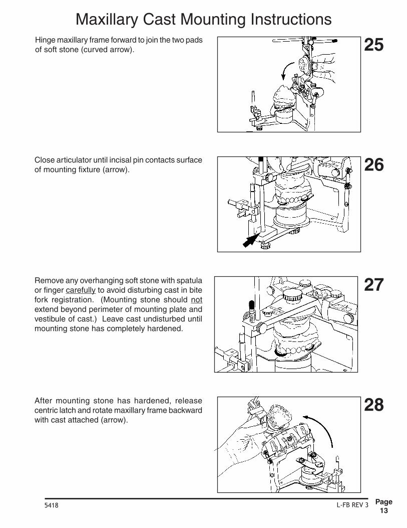
Hinge maxillary frame forward to join the two padsof soft stone (curved arrow).
Close articulator until incisal pin contacts surfaceof mounting fixture (arrow).
Remove any overhanging soft stone with spatulaor finger carefully to avoid disturbing cast in bitefork registration. (Mounting stone should notextend beyond perimeter of mounting plate andvestibule of cast.) Leave cast undisturbed untilmounting stone has completely hardened.
After mounting stone has hardened, releasecentric latch and rotate maxillary frame backwardwith cast attached (arrow).
25
26
27
28
Maxillary Cast Mounting Instructions

L-FB REV 35418Page
14
Remove maxillary cast from articulator. Cut backexcess stone (if any) projecting beyond perimeterof mounting plate and vestibule of cast.
For more secure and esthetic mounting, mixquick-set plaster to the consistency of whippedcream. Add reinforcement layer of plaster to castusing trimmed edge of cast and perimeter ofmounting plate as guides for plaster spatula.While plaster is still soft, use fingers underrunning tap water to smooth plaster surfaces.
Remove any residual plaster from mounting plateand ar ticulator before replacing cast onarticulator. When standard mounting plates arebeing used be sure to rotate mounted cast indirections the mounting plate screw is beingturned (arrows). Tighten mounting plate screwsecurely.
29
30
31
32
Remove mounting fixture, bite-fork assembly andbite-fork support. Replace incisal table.
Maxillary Cast Mounting Instructions
iu

L-IOR REV 25420Page
1
1
ITEMS USED FOR PROCEDURE:
1. Quick Drying Impression Tray Adhesive 2. Adhesive Brush 3. Baby Oil 4. Bowl of Warm Water 5. Bowl of Ice Water 6. Alcohol Torch 7. Matches or lighter 8. Bite-Trays (Panadent) 9. Soft Toothbrush10. Compound Stick11. Leaf Gauge (Panadent)12. Scissors13. Rubber Wheel on Mandrel14. Marking Ribbon and Holder15. Zip-lock Plastic Bags16. Cotton Roll17. 2x2 Gauze Pads18. Sharp Scalpel19. Bite Registration Material20. Paper Mixing Pad21. Cement Spatula
INTEROCCLUSAL RECORD INSTRUCTIONS
M Panadent Corporation580 S. Rancho Avenue • Colton, California 92324, USATel: (909) 783-1841 • USA & Canada (800) 368-9777 h 1210, 1211, 1230, 1231
These instructions apply to thefollowing items:

L-IOR REV 25420Page
2
2
3
4
5
Remove Panadent Bite-Trays from package.
Although Bite-Trays have been manufactured ina sanitary manner, trays should be sterilized priorto patient use. Sterilization of Bite-Trays may beby autoclave, chemclave or cold sterilizingsolution.
Paint Bite-Tray to be used with fast dryingimpression adhesive (e.g., Impergum) on bothsides in perforated areas only.
If maxillary cast of patient's teeth is available,place cast on Bite-Tray with incisors against up-turned anterior flange. Cut off extending portionof tray distal to second molars. Tray should coverfirst and second molars and distal extensionedentulous areas. Third molars should only beincluded if they are to be needed as bridgeabutments etc.
The first phase of maxillary registration is thesame (generic) as all types of interocclusalrecords (e.g., centric relation, protrusive as wellas lateral border).
INTEROCCLUSAL RECORD INSTRUCTIONS

L-IOR REV 25420Page
3
6
7
8
9
If maxillary cast is not available at time of recordmaking, place tray in patient's mouth to determinelength. Cut off distal end of tray extending beyondsecond molar areas.
Hold Bite-Tray with thumb and index finger atserrated areas on lateral edges of tray for placingtray in patient's mouth (arrows).
Remove any sharp edges of Bite-Tray withsandpaper disc, round stone, or abrasive rubberwheel.
Center tray laterally against patient’s maxillaryteeth with anterior up-turned flange restingagainst labial surface of incisors. Align midlinemark on up-turned flange with midsagittal ofmaxilla. With mandible retruded, have patient"bite down hard" on tray to adapt it to occlusalsurface of teeth (arrows).
INTEROCCLUSAL RECORD INSTRUCTIONS

L-IOR REV 25420Page
4
10
11
12
13
Mix bite registration paste. Spread about 1mmthick on maxillary side of tray in perforated areasonly.
Wipe off excess registration paste that flowsthrough perforations onto madibular side of traywith gauze pad.
Note: For patients with deep anterior verticaloverlap, (for example, class II div. 2), cutcompletely across perforated occlusal areas oftray on both sides just anterior to serratedgripping areas (arrow). Have patient "bite down"hard on tray to adapt it to teeth. This will causemetal to overlap in canine areas, thus allowingposterior teeth to come closer together.
After removing crushed tray from patients mouth,dry tray with compressed air.
INTEROCCLUSAL RECORD INSTRUCTIONS

L-IOR REV 25420Page
5
14
15
16
17
OPTIONAL: Dip entire bite tray briefly in bowl ofcold water before placing in the mouth.
Have patient use tongue to quickly lubricate teethwith saliva. Place loaded Bite-Tray in mouth andhold lightly against maxillary teeth (arrows).Instruct patient to tap mandibular teeth (inretruded position) against tray to assure tray isproperly repositioned.
While continuing to hold Bite-Tray in contact withmaxillary teeth (arrows) have patient open mouthslightly to separate mandibular teeth from tray.Hold tray against maxillary teeth in steady passivemanner until registration-paste hardens.
To remove Bite-Tray from patient’s mouth withoutwarping it, grasp tray with thumbs and indexfingers firmly on right and left flanges at premolararea; then shake tray vertically to break seal toteeth (arrows). Spraying mouth with cold watermay also be helpful in separating registration trayfrom teeth.
It is okay if maxillary occlusal and incisal contactsare made with the tray because tray is being heldin passive fashion against maxillary teeth.
INTEROCCLUSAL RECORD INSTRUCTIONS

L-IOR REV 25420Page
6
18
19
20
21
Trim excess material on maxillary side of Bite-Traywith sharp scalpel. Leave impressions of cusptips approximately 1mm deep. Also, remove anyhardened material that may have oozed out ontolower surface of tray.Note: If proper amount of registration paste wasused, above procedure is seldom necessary.
Remove all loose registration material fromocclusal areas with soft toothbrush under coldrunning tap water and dry record withcompressed air.
Clean all registration paste from patient's teethand face. Replace occlusal registration inpatient’s mouth to assure proper fit to maxillaryteeth. If registration does not fit perfectly to teeth,reline record with thin layer of registration materialor repeat total procedure using new Bite-Tray.
Place Bite-Tray in cold water (e.g. ice water) afew minutes to increase hardness of registrationmaterial.
Caution: Extreme care must be used whentrimming registration material to avoid warpingrecord.
Note: Magnification should be used to be sureall loose particles of material have been removedfrom record before proceeding.
INTEROCCLUSAL RECORD INSTRUCTIONS

L-IOR REV 25420Page
7
1
2
3
4
While rotating compound stick heat 3cm end untilstick begins to slump.
Spread hot compound about 2cm long and 1cmwide in anterior-posterior direction on Bite-Trayin area of mandibular incisors.
If compound should harden too quickly, reheatwith alcohol torch pressurized air stream.
Dry both sides of Bite-Tray thoroughly withcompressed air syringe. Especially dry loweranterior area of tray where hot compound is tobe added.
INTEROCCLUSAL RECORD (CENTRIC RELATION)

L-IOR REV 25420Page
8
5
6
7
8
Dip compound end of Bite-Tray about3-5 seconds in warm water (125°F / 40°C) totemper before placing in patient’s mouth.
While compound is still warm and pliable fitregistration to maxillary teeth. Hold tray againstmaxillary teeth with thumb and index finger ofone hand at lateral serrated areas of tray (bilateralarrows). Use thumb of other hand to hold lowerlip away from teeth. Place end of same thumbagainst labial surface of mandibular teeth.“Shake” mandible quickly two or three times whilepushing distally on lower anterior teeth to “break”muscle tension.
Have patient “relax jaw.” Continue to push distallywith forearm aligned in midsagittal plane ofpatient (this procedure may not be applicable forpatients with TMJ pain). Tell patient, “Do notbite, I will close your teeth for you”. Graduallyocclude teeth until mandibular incisors contactsoft compound (center vertical arrow) withoutposterior teeth touching tray.
As soon as mandibular incisors make properimpression in soft compound, instruct patient to“open your mouth quickly” (center arrow).Carefully remove tray from mouth withoutdisturbing soft compound.
Note: The following procedure is shown for righthanded operators. This should be consideredwhen done by left handed operators.
(If mandibular posterior teeth touching tray beforeanterior teeth touch compound, add morecompound to increase vertical dimension.However, keep vertical dimension to a minimumfor most accurate results.)
INTEROCCLUSAL RECORD (CENTRIC RELATION)

L-IOR REV 25420Page
9
9
10
11
12
Quickly harden compound by dipping Bite-Trayin bowl of cold water (e.g. ice water) for severalseconds.
It is recommended that a cotton roll, leaf gaugeor CR occlusal splint be placed between incisorsto keep posterior teeth separated to avoidneuromuscular reprogramming when record isnot in mouth.
Cut back excess cold compound with sharpstraight edged scalpel leaving mandibular incisorimpression no more than 1 mm deep (retrudedincisor registration).
Remove loose particles of compound fromretruded incisor registration with soft toothbrushand/or compressed air.
INTEROCCLUSAL RECORD (CENTRIC RELATION)

L-IOR REV 25420Page
10
13
14
15
16
Replace Bite-Tray in mouth to verify thatmandibular incisors were in most retrudedposition. If incisors can be made to touch behindoriginal indentions, warm compound with alcoholtorch and repeat procedure.
Check right and left sides of bite-tray with thickocclusal ribbon (e.g. .5mm) for absence ofmandibular posterior tooth contacts. If there iscontact, add more compound to increase verticaldimension and repeat procedure.
Note: If patient has unstable TM Joints, condylesmay go to higher position in fossae during brieftime patient is biting on hardened compoundregistration, thus causing lower posterior teethto come into contact with Bite-Tray.
Hold record firmly against maxillary teeth andhave patient tap mandibular incisors into retrudedcompound registration without assistance fromoperator to be sure index is comfortable,repeatable position for patient.
Note: Effects of head posture may be tested atthis time by having patient tip their head farbackward and far forward while tapping intoincisor registration to see if there are anydifferences.
Remove Bite-Tray from mouth and replace withcotton roll between incisors.
Note: There should only be mandibular incisaledge contact in compound (no labial or lingualcontacts).
INTEROCCLUSAL RECORD (CENTRIC RELATION)
L-IOR REV 25420Page
11
17
18
19
20
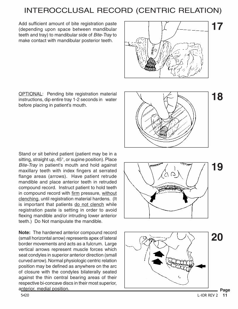
Add sufficient amount of bite registration paste(depending upon space between mandibularteeth and tray) to mandibular side of Bite-Tray tomake contact with mandibular posterior teeth.
OPTIONAL: Pending bite registration materialinstructions, dip entire tray 1-2 seconds in waterbefore placing in patient’s mouth.
Stand or sit behind patient (patient may be in asitting, straight up, 45°, or supine position). PlaceBite-Tray in patient's mouth and hold againstmaxillary teeth with index fingers at serratedflange areas (arrows). Have patient retrudemandible and place anterior teeth in retrudedcompound record. Instruct patient to hold teethin compound record with firm pressure, withoutclenching, until registration material hardens. (Itis important that patients do not clench whileregistration paste is setting in order to avoidflexing mandible and/or intruding lower anteriorteeth.) Do Not manipulate the mandible.
Note: The hardened anterior compound record(small horizontal arrow) represents apex of lateralborder movements and acts as a fulcrum. Largevertical arrows represent muscle forces whichseat condyles in superior anterior direction (smallcurved arrow). Normal physiologic centric relationposition may be defined as anywhere on the arcof closure with the condyles bilaterally seatedagainst the thin central bearing areas of theirrespective bi-concave discs in their most superior,anterior, medial position.
INTEROCCLUSAL RECORD (CENTRIC RELATION)

L-IOR REV 25420Page
12
21
22
23
24
Place cotton roll between teeth to keep posteriorteeth separated until record accuracy has beenverified.
Place record in a bowl of cold water (e.g. icewater) a few minutes to produce maximumhardness. Record can also be placed inrefrigerator to maximize hardness.
With sharp straight edge scalpel, cut back excessregistration material on mandibular side of trayuntil only cusp tip imprints about 1 mm deepremain.
Warning: must be used when cutting off excessregistration material to avoid warping or distortingthe record. (Handle record as though it were asfragile as an egg shell.)
To release mandibular teeth from registrationmaterial without warping tray; hold tray firmlyagainst maxillary teeth with fingers of both handsalong flanges (bilateral upward arrows); theninstruct patient to open mouth (downward arrow).In this way the chances of the teeth sticking inthe registration material and warping the Bite-Trayare greatly reduced.
INTEROCCLUSAL RECORD (CENTRIC RELATION)

L-IOR REV 25420Page
13
25
26
27
28
Remove loose registration particles from recordwith soft toothbrush under cold running tap water.
Dry centric relation record with compressed airand inspect finished product.
Note: Use magnification to be sure all loosematerial has been removed.
Replace finished record in patient's mouth andverify its accuracy.
Remove any artifacts from casts such as cusp orincisal edge impression perforations and bubbles.Fit previously made stone casts of patients teethinto impressions in centric relation record. If castsdo not fit registration impression in centric relationrecord, it is usually due to faulty casts rather thaninaccuracies in record, since record fit to teethwas verified.
INTEROCCLUSAL RECORD (CENTRIC RELATION)

L-IOR REV 25420Page
14
29
Clean residual material from patient’s face andlips with baby oil on a gauze pad.
If centric relation record is acceptable, place inair tight, zip-lock plastic bag with moist 2 x 2gauze pads soaked in sterilizing solution. Storerecord in protective cool place until ready for use.
30
INTEROCCLUSAL RECORD (CENTRIC RELATION)

L-IOR REV 25420Page
15
1
2
3
4
To make protrusive interocclusal record, firstrepeat figures 2-20 of interocclusal recordinstructions on a separate Bite-Tray to obtainregistration of maxillary teeth.
Verify fit of registration to maxillary teeth. Ifregistration does not fit perfectly, reline with thinlayer of fresh registration paste or discard record.Have patient practice retruding and protrudinghis/her “lower jaw” on command “forward” and“backward” so patient will understand thecommands when the anterior compound recordis made.
Note: Remove tray from mouth. Be sure to drylower side of tray with compressed air.
While rotating compound stick, heat about 3cmuntil stick begins to slump.
Spread hot compound approximately 1cm wideand 3cm long (on thoroughly dried Bite-Tray) inanterior posterior direction. Bring compoundanteriorly completely to flange.
INTEROCCLUSAL RECORD (PROTRUSIVE)

L-IOR REV 25420Page
16
5
6
7
8
Temper hot compound about 3 - 5 seconds inwarm water (125°F / 40°C) before placing inpatient’s mouth.
Note: The following procedure is shown for righthanded operators, which should be consideredwhen done by left handed operators.
Place upper-side impression carefully ontomaxillary teeth. Hold Bite-Tray firmly againstmaxillary teeth with thumb and index finger ofleft hand at second pre-molar flange areas(bilateral arrows). Place thumb of right handagainst mandibular incisors to hold mandible inmost retruded position (vertical arrow).
Have patient close slowly in most retrudedposition enough to make slight contact ofmandibular incisors with soft compound (arrow).
As soon as mandibular incisors contact softcompound, have patient immediately open mouth(vertical arrow). Note retruded impression ofteeth.
With teeth separated a few millimeters (arrow 1),have patient protrude mandible approximately 5-7mm(arrow 2).
INTEROCCLUSAL RECORD (PROTRUSIVE)

L-IOR REV 25420Page
17
9
10
11
12
With mandible protruded (avoid lateral deviation),instruct patient to bring teeth slowly together untilmandibular incisors make impression in softcompound (vertical arrow).
Have patient open mouth immediately (arrow).Note two impressions in compound (retruded andprotruded).
Remove tray carefully from patient's mouth to avoidtouching pliable compound and distorting it.
Inspect protrusive compound record to see thatit is approximately 5 - 7mm anterior to retrudedimpression. If record is unsatisfactory, warmcompound with alcohol torch and repeatrecording procedure.
Dip anterior end of tray immediately into bowl ofcold water (e.g. ice water) to harden compoundquickly.
INTEROCCLUSAL RECORD (PROTRUSIVE)

L-IOR REV 25420Page
18
13
14
15
16
With sharp straight edge scalpel, cut back excesscompound, leaving rather deep (3mm) protrusiveimpression of anterior teeth. (The reason forleaving the protrusive imprint deep is to help thepatient quickly relocate the recorded position withtheir mandibular incisors when the final stage ofthe recording is being done.)
Remove loose compound particles with softtoothbrush or air syringe.
Replace record in patient’s mouth to be sure itfits teeth. Make sure there are no mandibularposterior tooth contacts with Bite-Tray. Alsodetermine amount of registration paste neededto make contact between mandibular posteriorteeth and tray.
Check right and left sides with thick ribbon (e.g..5mm) for absence of mandibular posterior toothcontacts with Bite-Tray. If there is contact, addmore compound to increase vertical dimensionof record and repeat procedures.
INTEROCCLUSAL RECORD (PROTRUSIVE)

L-IOR REV 25420Page
19
17
18
19
20
Dip tray briefly in cold water before placing inmouth.
Hold tray firmly against maxillary teeth bi-laterallyat pre-molar areas (arrows). Have patient placemandibular anterior teeth in protrusive index.Instruct patient to bite firmly in index untilregistration material hardens. Continue to holdtray against maxillary teeth while registrationmaterial is setting to prevent posterior end of trayfrom separating from maxillary posterior teeth.
To release mandibular teeth from registrationmaterial without warping tray; hold tray firmlyagainst maxillary teeth with fingers of both handsalong flanges (bilateral upward arrows); theninstruct patient to open mouth (downward arrow).In this way the chances of the teeth sticking inthe registration material and warping the Bite-Tray are greatly reduced.
Mix an adequate amount of registration paste.Apply to right and left mandibular posterior areasof Bite-Tray. (Add excess amounts for distaledentulous areas in order to contact ridge.)
INTEROCCLUSAL RECORD (PROTRUSIVE)

L-IOR REV 25420Page
20
21
22
23
Cut back excess registration material with sharpscalpel, leaving impression of cusp tipsapproximately 1mm deep.
Remove loose registration particles with softtoothbrush under cold running tap water. Drywith compressed air. Inspect with magnificationto be sure all loose particles have been removed.
Place record in cold sterilizing solution. Sealrecord in Zip-lock bag with moist 2x2 gauze padsoaked in sterilizing solution. Store record inprotected cool place until ready to use.
Clean residual material from patient's face andlips with Baby Oil on gauze pad.24
INTEROCCLUSAL RECORD (PROTRUSIVE)

L-IOR REV 25420Page
21
1
2
3
4
To make left lateral interocclusal record, firstrepeat figures 2-20 of interocclusal recordprocedure on a separate Bite-Tray to obtainregistration of maxillary teeth.
Verify fit of impression to maxillary teeth. Ifimpression does not fit teeth, impression mustbe relined or redone. If impression is acceptable,dry lower side of tray thoroughly with compressedair.
While rotating compound stick, heat 3cm end untilstick slumps.
Spread 3cm portion of hot compound onmandibular side of dry Bite-Tray at left canine areajust anterior to serrated finger grips on edge oftray.
INTEROCCLUSAL RECORD (LEFT LATERAL)

L-IOR REV 25420Page
22
5
6
7
8
Temper compound two or three seconds in warmwater before placing in patient's mouth.
Seat Bite-Tray registration completely againstmaxillary teeth and hold in place with thumb andindex finger of one hand at pre-molar flangeareas. Place thumb of other hand againstmandibular incisors and hold patient in retrudedposition with teeth separated. Instruct patient tomove mandible slowly to the left (arrow).
Stop lateral jaw movement about 3mm (caninetip to tip). Have patient close slowly untilmandibular canine makes imprint 2-3mm deepin soft compound (vertical arrow).
As soon as mandibular canine has madeapproximately a 3mm imprint in soft compound,have patient "open mouth" immediately (verticalarrow).
INTEROCCLUSAL RECORD (LEFT LATERAL)

L-IOR REV 25420Page
23
9
10
11
12
Carefully remove tray from mouth. Hardencompound quickly by dipping registration in bowlof ice water. With sharp straight edge scalpel,remove all tooth imprints except canine cusp tip.Shave back canine imprints so it is between2-3mm deep.
Remove loose compound material with softtoothbrush under cold running water. Drycompound index with compressed air.
Clean all loose material from patient's teeth.Replace tray in mouth to make sure there are nomandibular posterior tooth contacts with tray.Have patient close into left lateral compoundindex to check fit of index to canine cusp tip.
Check both right and left sides to be sure thereis interocclusal space. A thick marking ribbon maybe used between mandibular teeth and tray tosee that there are no posterior contacts on eitherside. Also determine amount of registrationmaterial needed to make contact between trayand mandibular teeth.
INTEROCCLUSAL RECORD (LEFT LATERAL)

L-IOR REV 25420Page
24
13
14
15
16
Place adequate amount of bite registration pasteon mixing pad.
Be sure to add more paste to Bite-Tray oncontralateral (non-working) side and positionpaste somewhat lingually to register molars oncontralateral side (arrows). Add more than usualamount of material to register any distaledentulous ridge areas.
OPTIONAL, depending on operating timeneeded. Dip Bite-Tray briefly in cold water beforeplacing in patient's mouth to accelerate settingtime of bite registration paste in mouth.
Fit upper side registration carefully to maxillaryteeth and hold tray firmly against teeth with thumband index finger at pre-molar areas. Place wristand forearm against patient's forehead (arrows)to stabilize head against head-rest on dentalchair. Instruct patient to move mandible to theleft and place mandibular canine in compoundindex.
INTEROCCLUSAL RECORD (LEFT LATERAL)
L-IOR REV 25420Page
25
17
18
19
20
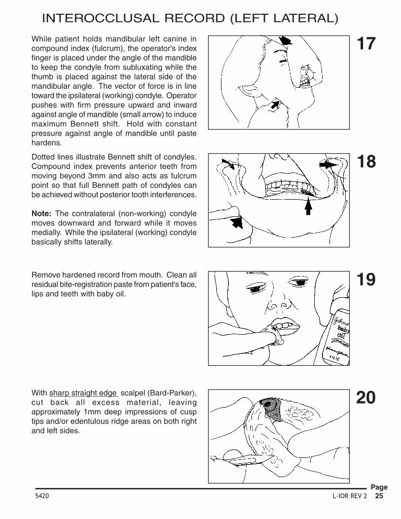
While patient holds mandibular left canine incompound index (fulcrum), the operator's indexfinger is placed under the angle of the mandibleto keep the condyle from subluxating while thethumb is placed against the lateral side of themandibular angle. The vector of force is in linetoward the ipsilateral (working) condyle. Operatorpushes with firm pressure upward and inwardagainst angle of mandible (small arrow) to inducemaximum Bennett shift. Hold with constantpressure against angle of mandible until pastehardens.
Dotted lines illustrate Bennett shift of condyles.Compound index prevents anterior teeth frommoving beyond 3mm and also acts as fulcrumpoint so that full Bennett path of condyles canbe achieved without posterior tooth interferences.
Note: The contralateral (non-working) condylemoves downward and forward while it movesmedially. While the ipsilateral (working) condylebasically shifts laterally.
Remove hardened record from mouth. Clean allresidual bite-registration paste from patient's face,lips and teeth with baby oil.
With sharp straight edge scalpel (Bard-Parker),cut back all excess material, leavingapproximately 1mm deep impressions of cusptips and/or edentulous ridge areas on both rightand left sides.
INTEROCCLUSAL RECORD (LEFT LATERAL)

L-IOR REV 25420Page
26
21
22
23
Remove loose registration particles with softtoothbrush under cold running water.
Dry completed registration with compressed airand make final inspection.
Wrap finished record in sterilizing solution soaked2x2 gauze. Place in sealed plastic bag. Storebag in sturdy plastic box for protection until readyto use.
INTEROCCLUSAL RECORD (LEFT LATERAL)

L-IOR REV 25420Page
27
1
2
3
4
Verify fit of upper impression to maxillary teeth.If impression does not fit teeth, impression mustbe relined or redone. If impression is acceptable,dry lower side of tray thoroughly with compressedair.
While rotating compound stick, heat 3cm end untilstick slumps.
Spread 3cm por tion of hot compound onmandibular side of dry Bite-Tray at right caninearea just anterior to serrated finger grips on edgeof tray.
To make right lateral interocclusal record, firstrepeat figures 2-20 of interocclusal recordprocedure on a separate Bite-Tray to obtainregistration of the maxillary teeth.
INTEROCCLUSAL RECORD (RIGHT LATERAL)

L-IOR REV 25420Page
28
5
6
7
8
Temper compound two or three seconds in warmwater before placing in patient's mouth.
Seat Bite-Tray registration completely againstmaxillary teeth and hold in place with thumb andindex finger of one hand at pre-molar flangeareas. Place thumb of other hand againstmandibular incisors and hold patient in retrudedposition with teeth separated. Instruct patient tomove mandible slowly to the right (arrow).
Stop lateral jaw movement about 3mm (caninestip to tip). Have patient close slowly untilmandibular canine makes imprint 2-3mm deepin soft compound (vertical arrow).
As soon as mandibular canine has madeapproximately a 3mm imprint in soft compound,have patient "open mouth" immediately (verticalarrow).
INTEROCCLUSAL RECORD (RIGHT LATERAL)

L-IOR REV 25420Page
29
9
10
11
12
Carefully remove tray from mouth. Hardencompound quickly by dipping registration in bowlof ice water. With sharp straight edge scalpel,remove all tooth imprints except canine cusp tip.Shave back canine imprints so it is between2- 3mm deep.
Remove loose compound material with softtoothbrush under cold running water. Drycompound index with compressed air.
Clean all loose material from patient's teeth.Replace tray in mouth to make sure there are nomandibular posterior tooth contacts with tray.Have patient close into right lateral compoundindex to check fit of index to canine cusp tip.
Check both right and left sides to be sure thereis interocclusal space. A thick marking ribbonmay be used between mandibular teeth and trayto see that there are no posterior contacts oneither side. Also determine amount of registrationmaterial needed to make contact between trayand mandibular teeth.
INTEROCCLUSAL RECORD (RIGHT LATERAL)

L-IOR REV 25420Page
30
13
14
15
16
Place adequate amount of bite registration pasteon mixing pad.
Be sure to add more paste to Bite-Tray oncontralateral (non-working) side and positionpaste somewhat lingually to register molars oncontralateral side (arrows). Add more than usualamount of material to register any distaledentulous ridge areas.
OPTIONAL, depending on operating timeneeded. Dip Bite-Tray briefly in cold water beforeplacing in patient's mouth to accelerate settingtime of bite registration paste in mouth.
Fit upper side registration carefully to maxillaryteeth and hold tray firmly against teeth with thumband index finger at pre-molar areas. Place wristand forearm against patient's forehead (arrows)to stabilize head against head-rest on dentalchair. Instruct patient to move mandible to theright and place mandibular canine in compoundindex.
INTEROCCLUSAL RECORD (RIGHT LATERAL)

L-IOR REV 25420Page
31
17
18
19
20
Dotted lines illustrate Bennett shift of condyles.Compound index prevents anterior teeth frommoving beyond 3mm and also acts as fulcrumpoint so that full Bennett path of condyles canbe achieved without posterior tooth interferences.
Note: The contralateral (non-working) condylemoves downward, foreward and medially whilethe ipsilateral (working) condyle basically shiftslaterally.
Remove hardened record from mouth. Clean allresidual bite-registration paste from patient's face,lips and teeth with baby oil.
With sharp straight edge scalpel (Bard-Parker),cut back all excess material leaving approximately1mm deep impressions of cusp tips and/oredentulous ridge areas on both right and leftsides.
The operator's index finger is placed under theangle of the mandible (pointing anteriorly) to keepthe condyle from subluxating while the thumb isplaced against the lateral side of the mandibularangle. The vector for inducing the Bennett shiftis in a line toward the ipsilateral (working) condyle.While patient holds mandibular right canine inindex, push medially with firm steady pressureagainst angle of mandible on contralateral (non-working) side to induce maximum amount ofBennett shift. Hold constant pressure againstmandible until paste is hard.
INTEROCCLUSAL RECORD (RIGHT LATERAL)

L-IOR REV 25420Page
32
21
22
Remove loose registration particles with softtoothbrush under cold running water.
Dry completed registration with compressed airand make final inspection.
23 Wrap finished record in sterilizing solution soaked2x2 gauze. Place in sealed plastic bag. Storebag in sturdy plastic box for protection until readyto use.
INTEROCCLUSAL RECORD (RIGHT LATERAL)
i

L-MAND REV 35421 Page1
1
2
3
4
Grind mandibular mounting surface of castparallel to occlusal plane of teeth with modeltr immer. Grind perimeter of cast withapproximately 10-15o bevel to depth of buccaland labial vestibules. Avoid touching teeth orbuccal and labial gingival areas with trimmerwheel.
Cut retention grooves in trimmed cast withlaboratory knife or carborundum disc.
Score mounting surface of cast with laboratoryknife or carborundum disc.
MANDIBULAR CAST MOUNTING INSTRUCTIONS
h2280,1210,1211,1230,1231
M Panadent Corporation580 S. Rancho Avenue • Colton, California 92324, USATel: (909) 783-1841 • USA & Canada (800) 368-9777
Raise and lock maxillary frame against incisalpin about 3-4 mm above heavy "0" ring dependingon thickness of centric record. (If verticaldimension is not being changed by thickness ofcentric record, i.e. closed-bite interocclusalrecord, leave incisal pin set at "0").Note: The raising of the maxillary frame on theincisal pin is an arbitrary procedure and does notchange the relationship of the occlusal surfacesof the maxillary teeth to the protrusive path whichwill be set in the articulator at a later time.
These instructions apply to the following items:

L-MAND REV 35421Page
2
5
6
7
8
Rotate centric latch forward to engage latch withaxis shaft and depress centric pin into centricchannel of lower frame of articulator.
The mandibular mounting stand has two holelocations. The top hole is used for High (H) modelarticulators; the bottom hole is used for Low (L)model articulators.
Grasp articulator upside down in one hand andvertical support arm of mounting stand with otherhand. Insert "far side" extending analog axis pininto appropriate hole in mounting stand.
MANDIBULAR CAST MOUNTING INSTRUCTIONS
Flex "near side" vertical support arm outward toallow arm to spring inward and capture extendingend of analog axis pin in appropriate hole insupport arm.

L-MAND REV 35421 Page3
9
10
11
12
Hinge mandibular frame back to open position.Adjust and lock support pin with thumb screw.
Place centric record carefully on maxillary castand verify fit. Pay particular attention to see thatthere are no contacts of centric record materialwith soft tissue unless it is a designated area tosupport a distal edentulous ridge.
Remove any occlusal bubbles or artifacts ifpresent in tooth area of mandibular cast. Placemandibular cast carefully into cusp tipimpressions in centric record and verify fit.
MANDIBULAR CAST MOUNTING INSTRUCTIONS
Close mandibular frame of articulator over castuntil incisal pin touches incisal table to determineamount of plaster needed for mounting. Grindmounting surface of cast if necessary so therewill be at least a 5mm space between mountingplate and cast (area indicated by spatula).

L-MAND REV 35421Page
4
Mix quick set mounting stone to consistency ofwhipped cream. Place amount of soft stone firston mounting plate, being sure to get stone intoretention areas of plate.
Place minimum amount of soft stone on mountingsurface of cast to make connection with stoneon mounting plate.Note: Do not add more stone than required tomake a small to moderate sized connection. Ifthe mounting space is large it is best to build upon the cast and mounting plate and allow thisstone to harden. Then make the final connectionwith a small amount of stone to keep theexpansion errors to a minimum.
13
14
15
16
Adjust length of support post to level mountingsurface of mandibular cast (arrow).
Spray entire mandibular frame, including condylarelement and analogs with silicone lubricant spray.Also spray the mounting stand for protection ofstand and easy removal of any residual mountingstone.
MANDIBULAR CAST MOUNTING INSTRUCTIONS

L-MAND REV 35421 Page5
17
18
19
20
Close mandibular frame to join two pads of softmounting stone until end of incisal pin rests onincisal table (arrow). Press cast tightly into centricrecord with thumb and fingers at premolar areas(arrows) while palm of hand rests on frame ofarticulator. Hold in this manner until quick-setstone reaches initial set. Then remove hand andleave articulator undisturbed until mounting stonehas completely hardened.
MANDIBULAR CAST MOUNTING INSTRUCTIONS
Remove articulator from mounting stand by firstpulling laterally on one support arm of stand toflex arm sufficiently to release axis pin of analog(arrow) and then twist articulator slightly to freeextending analog axis pin from support arm.
Pull articulator toward you to release other analogaxis pin from its support arm on mounting stand.Lift articulator upward and away from mountingstand.
Release centric latch to allow for easy removalof centric record.

L-MAND REV 35421Page
6
When mounting stone has hardened, loosenmounting plate screw and remove cast from lowerframe.
For added strength and esthetics, add soft mix ofquick-set plaster using edge of mounting plateand cut edge of buccal and labial vestibules ofcast as guides for spatula. Allow plaster to reachfinal set.
Remove any residual plaster on mounting plateand articulator mounting surface and replacemandibular cast on articulator. Always rotate castin direction the mounting screw is being tightenedto maintain highest accuracy.
21
22
24
23
Lift upper frame of articulator and carefullyremove centric record from casts.
MANDIBULAR CAST MOUNTING INSTRUCTIONS
i

Page1 L-AI REV 35409
1
2
3
4
Raise and lock incisal pin and support pin (arrow)at least 5mm above incisal table.
Loosen thumb screws and retract right and leftDyna-Link pins (arrow).
Place Dyna-Link pins in storage holes inarticulator legs (arrow).
Release centric latch (arrow) to allow centric pinto spring upward and lift lower end of pin out ofcentric channel in mandibular frame. (If centricpin does not spring upward when latch isretracted, rotate centric pin cap to release it.)
Articulator InstructionsM Panadent Corporation580 S. Rancho Avenue • Colton, California 92324, USATel: (909) 783-1841 • USA & Canada (800) 368-9777 hhhhh1610,1620,1701,1801,1210,1211,1230,1231
These instructions applyto the following items:

Page2 L-AI REV 35409
5
6
7
8
Separate maxillary frame from mandibular frameof articulator.
Stretch elastic band on lower surface ofmandibular frame over extending latch arm tokeep latch retracted back and down out of theway.
Loosen right and left analog shaft lock screwswith hex wrench.
Rotate and lock both motion analogs in their "0"positions using only thumb screws to maintainposition. The "0" line should be equal to the uppersurface of the analogs. The analogs should bein contact with the calibrated sides of thearticulator.

Page3 L-AI REV 35409
9
10
11
12
Place protrusive interocclusal record onmandibular cast. Fit maxillary cast vertically intoprotrusive record. (Be sure centric and incisalpins have been raised.)
While placing straight downward pressure onmaxillary cast (vertical arrows) to keep maximumcontact with protrusive record, loosen incisal pinscrew and allow incisal pin to drop down to makecontact with incisal table (horizontal arrow). Lockincisal pin firmly before proceeding.
Note: This procedure produces a larger tripodalong with the casts and protrusive record forbetter stabilization.
While continuing downward pressure above cast,loosen thumb screw and allow right side analogto "fall" (rotate) downward to contact superiorsurface of condylar element (curved arrow).Tighten axis shaft thumb screw to hold the analogangular position.
While holding downward pressure on the castswith one hand, move the other hand to grasp theright analog thumb screw.

Page4 L-AI REV 35409
13
14
15
16
Angular setting is read where upper surface ofanalog corresponds to a calibration line on sideof articulator (arrow).
After analog angulations have been obtained,make sure analogs are in contact with calibratedsides of articulator. Tighten both analog axis shaftlock screws with hex wrench to retain analogangulation.
Reinsert right and left Dyna-Link pins (arrow) andlock in place with retaining thumb screws.Release elastic centric latch hold down andengage centric latch over centric pin cap.
While maintaining downward pressure on casts(large arrow), loosen left side axis shaft thumbscrew to obtain angular inclination for left side. Ifanalog does not rotate freely downward intocontact with condylar element, tap lightly on upperanterior surface of analog.Note: If the patient's condyles did not protrudesymetrically, it may be necessary to move theanalogs slightly laterally away from the calibratedside of the articulator to make contact withcondyle element.

Page5 L-AI REV 35409
17
18
19
20
When centric latch is engaged and articulator isclosed, extending arm of latch automaticallydepresses centric pin (arrow) and places lowerend of centric pin in centric channel of mandibularframe.
Centric pin engaged in centric channel (arrow).Eccentric movements (lateral & protrusive) shouldnever be attempted when centric latch is engagedor when centric pin is in centric channel.
To occlude casts in centric relation, raise and lockincisal pin and support post both about 5mmabove incisal table. Hinge maxillary frame bylifting up on lower end of incisal pin.
To execute protrusive and lateral movements,release centric latch by pushing distally onprotruding end of latch (arrow). Be sure centricpin springs upward to disengage centric channelon mandibular frame.

Page6 L-AI REV 35409
21
22
23
24
If centric pin does not spring upward when latchis released, rotate centric pin cap (arrow) torelease it.
Depress centric pin cap with finger (arrow) totemporarily locate centric relation during use ofinstrument. (Hinging movement can be madewith centric pin depressed but lateral movementsshould never be attempted with centric locatorpin in depressed position.)
Centric pin out of centric channel (arrow). Lateraland protrusive movements can now be made.
To make protrusive - retrusive movement, graspvertical frame of articulator with one hand.Separate casts by pushing down on incisal table(lifting up on incisal pin). Then pull forward onincisal table (push distally on incisal pin) (arrows)until incisor teeth are edge to edge. Slowlyrelease finger pressure and allow mandibularframe to retrude to centric relation.

Page7 L-AI REV 35409
25
26
27
28
To occlude teeth in a right lateral chewing motion,grasp end of incisal pin with thumb and indexfinger and left maxillary frame (depressmandibular) to separate teeth. Then movemandibular frame right (incisal pin left)approximately 3mm (cuspid to cuspid). Bringcasts slowly into cuspid contact. Keep slightforward pressure on incisal pin to assure condylarborder movement while occluding cast slowlyback to centric relation.
For left lateral movement use same basicprocedure as for right lateral movement.
To reconnect centric latch when articulator isclosed, rotate latch upward and forward withfingers (curved arrow) until cradles of latchengage analog axis shafts. (This procedure willautomatically depress centric pin into centricchannel of mandibular frame of articulator.)
Centr ic latch can also be engaged whenarticulator is in open position by exerting distalpressure on latch bar with fingers (arrow).

Page8 L-AI REV 35409
29
30
31
To lock centric locator pin in down position whencentric latch is disengaged, place finger on flangeof pin cap (arrow)
then depress centric pin cap and rotate clockwise(arrows).
Lingual approach to teeth is accomplishedthrough lingual access area of articulator.
32 When articulator is not in use, it is recommendedthat incisal pin be locked in contact with incisaltable (arrow), slightly separating the teeth toprevent tooth breaking from casts.
iu

L-MSII REV 35405
Magna-Split II System Instructions
1 2
3 4Fasten Metal Mounting Plate toArticulator with fastening screws.
Attach Magnet to Mounting Platewith mounting plate screw.
Place plastic index plate to metalmagnetic mounting plate.
Add plaster to plastic index plateand study cast to mount models inusual manner.
5 6
To prevent losing the magnetassembly, Do not try to removeyour casts by unscrewing the knob,the magnet housing and magnetwill fall out or stay with the mountedcasts.
To prevent casts from separating frommounting plate, grasp the cast andmounting plate with thumb and fingers.Tilt the mounted cast assembly sidewaysto release cast from mounting platemagnet. (Do not pull on mounted casts.)
Check to make sure your magnet is still on your articulator, without a magnet, your stone transfer plates will not connect.
i
M Panadent Corporation580 S. Rancho Avenue • Colton, California 92324, USATel: (909) 783-1841 • USA & Canada (800) 368-9777
2860: If used more than one time, insert may come loose and plate will no longer index to base plate.D
h2850, 1610, 1620, 1210,1211, 1230, 1231
Includes:2860D
These instructions apply to the following items: