basic classic - medident exim...instruction manual • mode d’emploi istruzioni d’uso •...
TRANSCRIPT

Made in Germany
Basic classicNo. 2947
2166
38 1
7112
015
/ B
Ideas for dental technology
BedienungsanleitungInstruction manual • Mode d’emploi
Istruzioni d’uso • Instrucciones de servicioИнструкция по эксплуатации
操作说明书 • 取扱説明書 • 사용 설명서
- 1 - EN
Basic classicNo. 2947
ENGLISH
1. Introduction .......................................................................................................................................... 11.1 Employed Symbols ................................................................................................................. 1
2. Safety ..................................................................................................................................................... 22.1 Intended use............................................................................................................................... 22.2 Improper use .............................................................................................................................. 22.3 Environmental conditions for safe operation .............................................................. 22.4 Hazards and warnings........................................................................................................... 22.5 Authorised persons ................................................................................................................. 32.6 Liability Exclusion .................................................................................................................... 3
3. Product description .......................................................................................................................... 33.1 General description ................................................................................................................. 33.2 Components and functional elements ........................................................................... 33.3 Standard Delivery .................................................................................................................... 43.4 Accessories ................................................................................................................................ 4
4. Commissioning .................................................................................................................................. 44.1 Installation ................................................................................................................................... 44.2 Foot switch connection ......................................................................................................... 44.3 Compressed air connection ................................................................................................ 44.4 Electrical connection .............................................................................................................. 54.5 Connection to suction device ............................................................................................. 54.6 Adjusting the Operating Pressure .................................................................................... 54.7 Filling the Sandblasting Tanks ........................................................................................... 5
4.7.1 Authorised sandblasting material ............................................................................................ 55. Operation .............................................................................................................................................. 5
5.1 Blasting Notes ........................................................................................................................... 65.2 Cold silanization in the sandblasting unit ..................................................................... 6
6. Cleaning / Maintenance ................................................................................................................ 66.1 Cleaning the Interior ............................................................................................................... 66.2 Condensation ............................................................................................................................. 66.3 Blasting Nozzle Replacement ............................................................................................ 66.4 Cleaning the dosing nozzle ................................................................................................. 66.5 Lamp cover ................................................................................................................................. 66.6 Spare Parts ................................................................................................................................. 66.7 Shipping Notes .......................................................................................................................... 7
7. Trouble shooting ............................................................................................................................... 78. TechnicalSpecifications ................................................................................................................ 79. Warranty ............................................................................................................................................... 810. Disposing of the Unit ...................................................................................................................... 8
10.1 Information on disposal for countries within the EC ............................................ 8
1. Introduction1.1 Employed Symbols
Intheseinstructionsorontheunititselfyouwillfindsymbolswhichhavethefollowingmeaning: Danger
This indicates an imminent risk of injury. In these instructions or on the unit itself you will find symbols which have the following meaning:
Electrical hazard There is a risk of electrical shock.
Attention Failure to observe the associated information can result in damage to the unit.
Note The operating instructions contain useful information to make handling easier.
Attention! Wear eye protection.
The unit complies with the relevant EC guidelines.
The unit is subject to the EC guidelines 2002/96/EG (WEEE Directive).
Further symbols are described by their uses.
EN

- 2 -EN
2. Safety Inform the operator about working procedures, possible operating hazards and actual operation of the unit
with these user instructions.Ensurethattheseinstructionsareavailablefortheoperator.
2.1 Intended useTheBasiclineofsandblastingunitsaredesignedforuseindentallaboratoriestoremoveinvestmentresidues,oxidesoncastobjects,andforsurfacetreatment.Otherareasofusealsoincludedivestingpressceramicorsandblastingporcelainocclusalsurfaces.
2.2 Improper useOnly spare parts and accessories supplied or authorized by Renfert GmbH may be used with this product. If other sparepartsoraccessoriesareused,thiscouldhaveadetrimentaleffectonthesafetyofthedevice,increasetheriskofseriousinjuryandleadtodamagetotheenvironmentorthedeviceitself.
2.3 Environmental conditions for safe operationSafeoperationofthisunitcanbeguaranteedunderthefollowingconditions: - Indoors, - Uptoanaltitudeof2,000m[6,500ft]abovesealevel, - Atanambienttemperatureof5-40°C[41-104°F]*), - Atamaximumrelativehumidityof80%at31°C[87.8°F],decreasinglinearlyto50%relativehumidity at40°C[104°F]*),
- Withamainspowersupplywherecurrentfluctua-tionsdonotexceed10%ofthenominalvalue, - Underlevel2contaminationconditions, - UnderovervoltagecategoryIIconditions.*) Between5–30°C[41-86°F],theunitcanbeoperatedatarelativehumidityofupto80%.Attemperaturesbetween31-40°C[87.8-104°F],
thehumiditymustdecreaseproportionallyinordertoensureoperationalreadiness(e.g.,at35°C[95°F]=65%humidity;at40°C[104°F]=50%humidity).Theunitmaynotbeoperatedattemperaturesabove40°C[104°F].
2.4 Hazards and warnings ► If the unit is not used according to the instructions for use, then protection can no longer be guaranteed. ► The unit may only be used together with a mains cable with a country specific plug system. If a plug ex-change is necessary, this may only be undertaken by a skilled electrician. ► The mains plug must be easy to access. ► Check connection cables (e.g. power cable), tubes and housing (e.g. operating key pad) regularly for dam-age (e.g. kinks, cracks, porosity) or aging. Appliances with damaged connection cables, tubes or housing parts or other defects must no longer be operated! Remove the power cable and secure against being switched on again! ► Risk of Injury! If unauthorised attachments are used, there is a danger of injury. Only original Renfert fittings and acces-sories may be used. ► Please observe the accident prevention regulations provided by the „employer‘s liability insurance associ-ation“! ► Always disconnect the unit from the compressed air and power sources prior to beginning any mainte-nance work. ► When working on the tank (filling up, cleaning, maintenance) wear protective glasses for protecting your eyes. ► Any residue of abrasive material on the gasket may lead to leakage and early wear of the gasket. After filling up clean the thread and the gasket and close the lid properly. ► DO NOT use solvent-containing cleaning agents or disinfectants. ► Solvents and tensides can create micro-cracking in the plastic (danger of explosion!). Clean the tank and the lid only with a dry cloth. Do not write or stick something on the tanks. ► Do not unscrew the tank lid as long as the pressure had not been released ► Check the tanks and the lids regularly on damages and replace them in case of doubt. ► Check the tank cover for correct seating prior to beginning operation. Covers that are not securely closed can suddenly be blown off as the tank pressure increases. The resulting flying parts and abrasive repre-sent a serious hazard. ► Never operate the blasting units without suitable dust extraction and appropriate protective gear, as this could result in health hazards. The type of dust extraction should be selected on the basis of the dust be-ing generated. Follow here absolutely EN 60335-2-69 appendix AA or ask the appropriate authorities. ► Improper use can result in the risk of eye or skin injuries. ► Never direct the blasting material towards eyes or unprotected areas of skin! ► Never work with the view screen open! ► Caution: Failure to wear proper eye protection can result in eye injury due to particles suspended in the air. Always wear proper eye protection to protect your vision!
EN
- 3 - EN
► Do not employ the foot switch when only the compressed air supply hose is connected. The loose hose could wrap around itself and cause serious injury. ► It is the responsibility of the operator that national regulations during operation and regarding a repeated safety inspection of electrical equipment are complied with. For Germany these are BGV A3 in relation with VDE 0701-0702.
2.5 Authorised personsThisproductmayonlybeusedbypersonsovertheageof14.Operationandservicemayonlybecarriedoutbytrainedpersonnel.Repairswhicharenotdescribedintheseinstructionsmayonlybecarriedoutbyskilledelectriciansand the specialist dealers.
2.6 Liability ExclusionRenfertGmbHshallbeabsolvedfromallclaimsfordamagesorwarrantyif:
► The product is employed for any purposes other than those cited in the operating instructions. ► The product is altered in any way other than those alterations described in the operating instructions. ► The product is repaired by other than an authorized facility or if any but Renfert OEM parts are employed. ► The product continues to be employed, despite obvious safety faults. ► In the case of mechanical impact or if the unit is dropped. ► Accessories or consumer products used, which are not supplied or authorised by Renfert GmbH.
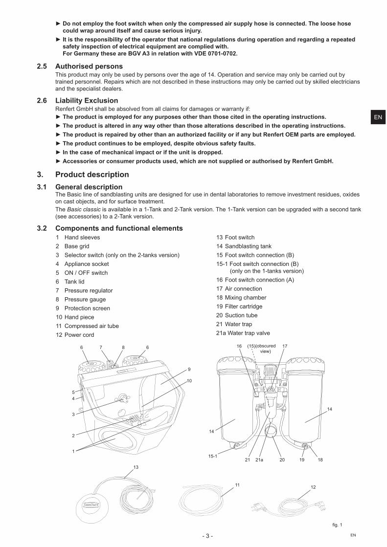
3. Product description3.1 General description
TheBasiclineofsandblastingunitsaredesignedforuseindentallaboratoriestoremoveinvestmentresidues,oxidesoncastobjects,andforsurfacetreatment.The Basic classicisavailableina1-Tankand2-Tankversion.The1-Tankversioncanbeupgradedwithasecondtank(seeaccessories)toa2-Tankversion.
3.2 Components and functional elements1 Handsleeves2 Base grid3 Selectorswitch(onlyonthe2-tanksversion)4 Appliancesocket5 ON / OFF switch6 Tanklid7 Pressure regulator8 Pressure gauge9 Protection screen10 Hand piece11 Compressed air tube12 Power cord
13 Foot switch14Sandblastingtank15Footswitchconnection(B)15-1Footswitchconnection(B)
(onlyonthe1-tanksversion)16Footswitchconnection(A)17 Air connection18Mixingchamber19 Filter cartridge20 Suction tube21 Water trap21aWatertrapvalve
6 6
10
2
11
13
1
14
14
21a
3
8
20
7
45
12
16
15-1
(15) 17
21 1819
9
fig.1
(obscured view)
EN

- 4 -EN
3.3 Standard Delivery1 Basic classic1 Foot switch1 Connection set1 SetofOperatingInstructions,withattachment1 Power cord
3.4 AccessoriesRetrofit tanks2947-0050 Basic classicRetrofittank25-70µm2947-0250 Basic classic Retrofittank70-250µmAbrasivesCobra aluminium oxide 1594-1105 25µm[500mesh],white5kgcanister1594-1205 50µm[270mesh],white5kgcanister1594-2220 50µm[270mesh],white20kgbucket1584-1005 90µm[170mesh],white5kgcanister1583-1005 110µm[150mesh],white5kgcanister1583-1020 110µm[150mesh],white20kgbucket1587-1005 125µm[115mesh],pink5kgcanister1587-1020 125µm[115mesh],pink20kgbucket1585-1005 250µm[60mesh],white5kgcanister1585-1020 250µm[60mesh],white20kgbucket
Rolloblast glass beads1594-1305 50µm[400-200mesh]5kgcanister1594-2312 50µm[400-200mesh]12.5kgcanister1589-1005 100µm[170-100mesh]5kgcanister
NozzlesRound nozzles90002-1203 0,4mm [0.0158inch]90003-3213 0,65mm[0.0256inch]90002-1204 0,8mm [0.0315inch]90003-3211 1,0mm [0.0394inch]90003-3214 1,2mm [0.0473inch]90002-1205 1,4mm [0.0552inch]90002-1206 2,0mm [0.0788inch]
Slotted nozzles90003-1739 1,5x3,5mm[0.0591x0.1379inch]
4. Commissioning4.1 Installation
Choose a stable and non-slip surface to stand the unit on.
4.2 Foot switch connection• Removethefootswitchfromitsshippinglocationintheblastingchamber.• Inserttheendofthetubemarkedwithan„A“(13)asfarasitwillgointothetubeconnectionpointalsomarkedwithan„A“(16)ontheblastingunit.
• Inserttheendofthetubemarkedwithan„B“(13)asfarasitwillgointothetubeconnectionpointalsomarkedwithan„B“ontheblastingunit. 2-tankversion:(15) 1-tankversion:(15-1,Abb.1)
Wheninsertingthetubesyouwillnoticeaslightresistancewhichmustbeovercome.
fig.2
13
15
16
4.3 Compressed air connection• Pushthecompressedairtube(11)ontothetubeconnectionpoint(17)asfarasitwillgo.Indoingsotherewillbeaslightresistancetoovercome.
• Toconnecttothecompressedairsystem,selecttherelevanttubecouplingfromthesup-plied set and attach this to the other end of the tube.
• Attachtothecompressedairnetwork.
fig.3
11
17
EN

- 5 - EN
4.4 Electrical connection Ensure that the voltage information on the type plate and the mains voltage are com-
patible.• Plugthemainscable(12)intothesocket(4).• Plug in the mains cable.
12 4
fig.4
4.5 Connection to suction device• Plugthesuctiontubefromtheextractionunittothesuctionpipe(20).• Forsuctiondeviceswithautomaticactivation:connectthemainsplugfromthesandblastingunitintotheusersocketonthesuctiondevice.
fig.5
(20)
4.6 Adjusting the Operating Pressure• Activatethefootswitch.• Setthesandblastingpressure(1-6bar/14.5-87psi)atthepressureregulator(7).Theamountofpressurewillbeshownonthepressuregauge(8).Inthe2tankversiontheamountofpressureselectedappliesforbothblastingtanks.
4.7 Filling the Sandblasting Tanks Attention: Never press the foot switch during filling.
Even though the manometer may indicate pressure, the sandblasting tanks are only under pressure if the foot switch is engaged.• Addabrasiveuptothemaximumfilllevel(thepointwherethetankjacketthickensjustbelow thethread).
• Reinstallthetankcover. Before closing the tank, be sure to clean the threads in the cover and the tank to remove
any abrasive residue.
Caution: Do not tilt the tank lid when unscrewing.
Alwaysuseonlyclean,dryabrasiveoftheappropriategrainsize(refertotheaccessories).The sandblasting unit is now operational.
4.7.1 Authorised sandblasting material• Cobra(RenfertGmbH)• Rolloblast(RenfertGmbH)• ROCATEC(3MESPE)Sandblastingmaterialsfromothermanufacturersmaybeusedprovidingthegrainsize,grainshapeanddegreeofpuritycomplywiththeabovementionedmaterials.ThecompanyRenfertGmbHassumesnoliabilityforfunctionanddurability of the units if other sandblasting material is used.
fig.6
7 8
fig.7
max
5. Operation• Switchtheilluminationon(5).
If the membrane key is damaged or defect, please disconnect the device and send away for repair! If the membrane is removed there is the risk of an electrical shock!• Selecttheblastingtankattheselectionswitch(3,fig.1)(onlyonthe2-tanksversion).
Do not operate the foot switch during tank selection.
• Taketherespectivehandpiecefromtheselectedblastingtank(seecolouredmarking).• Activatethefootswitch(13,fig.1).Thesandblastingmaterialwillflowaslongasthefootswitchisactivated.
5.1 Blasting NotesFlatblastingwithwidenozzles:90003-1739 1,5x3,5mm[0.059x0.138inch]Whenblastingglassceramics,refertomanufacturer‘snotes.
5
fig.8
EN

- 6 -EN
5.2 Cold silanization in the sandblasting unitTheBasicseriesofRenfertsandblastingunitsisexclusivelyrecommendedby 3MESPEforusewithROCATEC™.Thisbondingsystemisidealifanadhesivebondisrequiredbetweenacompos-iteandadentalmaterial(metal,acrylic,porcelain,zirconiaporcelain).Advantage:Thesurfacefilmisappliedcold,preventingthermalloadingofmetalframeworksandconsequentlytheriskofdistortion.AllunitsintheBasicseriescanbeusedforROCATEC™duetotheirregular,homogeneousjetflow.
6. Cleaning / Maintenance Before cleaning or servicing:
► Switch off and unplug the device! ► Disconnect the appliance from the compressed air supply!
6.1 Cleaning the Interior• DONOTusesolvent-containingcleaningagentsordisinfectants.(usee.g.,soapywater)• Removethegrateandvacuumtheblastingchamber.• Wipeoutthetanksandlidsonlywithadrycloth!
fig.9
6.2 Condensation• Inspectthewaterseparator(21).• Drainanywateroffthroughthevalve(21a).
6.3 Blasting Nozzle Replacement• For installation see accessory supplement.
fig.10
21a
21
6.4 Cleaning the dosing nozzleThedosingnozzlefromthemixingchambercanbecomeblockedduetocontaminationand moist blasting sand.Forcleaning,thedosingnozzleisremovedusingthesuppliedtoolandreplacedaftercleaning.• Vacuumcleantheblastingtankcompletely.• Holdthedosingnozzlewiththetoolandpullupwards(fig.11).• Cleanthedosingnozzle(e.g.blowwithcompressedair).• Replace dosing nozzle.
Before remounting, the dosing nozzle should be completely dry!
• Thedosingnozzlemustbeadjustedwithblastingtanksof25-70µm(fig.12)! see also supplement „Cleaning the dosing nozzle“
fig.11
fig.12
6.5 Lamp coverInthecourseoftime,thelampcovercanbecomematt.Thiscovercanbeorderedasasparepart.
6.6 Spare PartsYoucanfindcomponentssubjecttowearandthesparepartsonthesparepartlistintheinternetat www.renfert.com/p918.Thecomponentsexcludedfromthewarranty(suchasconsumablesorpartssubjecttowearandtear)aremarkedonthe spare part list.Serial number and date of manufacturing are shown on the type plate of the unit.
6.7 Shipping Notes• Emptyallblastingtanks.• OrderRenferttransportpackaging(Tel.+4977318208-383).
Thereturnformcanbedownloadedfromthe„Advice“sectionontheRenfertwebsiteatwww.renfert.com.
EN
- 7 - EN
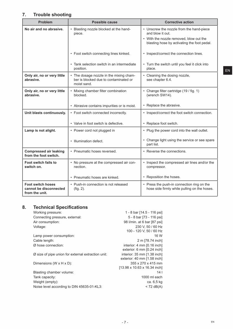
7. Trouble shootingProblem Possible cause Corrective action
No air and no abrasive. • Blastingnozzleblockedatthehand-piece.
• Footswitchconnectinglineskinked.
• Tankselectionswitchinanintermediateposition.
• Unscrew the nozzle from the hand-piece and blow it out.
• Withthenozzleremoved,blowouttheblastinghosebyactivatingthefootpedal.
• Inspect/correct the connection lines.
• Turntheswitchuntilyoufeelitclickintoplace.
Only air, no or very little abrasive.
• Thedosagenozzleinthemixingcham-berisblockedduetocontaminatedormoist sand.
• Cleaningthedosingnozzle, see chapter 6.4.
Only air, no or very little abrasive.
• Mixingchamberfiltercombinationblocked.
• Abrasivecontainsimpuritiesorismoist.
• Changefiltercartridge(19/fig.1) (wrenchSW14).
• Replacetheabrasive.
Unit blasts continuously. • Foot switch connected incorrectly.
• Valveinfootswitchisdefective.
• Inspect/correct the foot switch connection.
• Replace foot switch.
Lamp is not alight. • Power cord not plugged in
• Illumination defect.
• Plug the power cord into the wall outlet.
• Changelightusingtheserviceorseesparepart list.
Compressed air leaking from the foot switch.
• Pneumatichosesreversed. • Reversetheconnections.
Foot switch fails to switch on.
• No pressure at the compressed air con-nection.
• Pneumatichosesarekinked.
• Inspect the compressed air lines and/or the compressor.
• Reposition the hoses.
Foot switch hoses cannot be disconnected from the unit.
• Push-in connection is not released (fig.2).
• Press the push-in connection ring on the hosesidefirmlywhilepullingonthehoses.
8. Technical SpecificationsWorkingpressure: 1-8bar[14.5-116psi]Connectingpressure,external: 5-8bar[73-116psi]Airconsumption: 98l/min.at6bar[87psi]Voltage: 230V,50/60Hz 100-120V,50/60HzLamppowerconsumption: 16WCablelength: 2m[78.74inch]Øhoseconnection: interior:4mm[0.16inch] exterior:6mm[0.24inch]Øsizeofpipeunionforexternalextractionunit: interior:35mm[1.38inch] exterior:40mm[1.58inch]Dimensions(WxHxD): 355x270x415mm [13.98x10.63x16.34inch]Blastingchambervolume: 14lTankcapacity: 1000mleachWeight(empty): ca.6,5kgNoiselevelaccordingtoDIN45635-01-KL3: <72dB(A)
EN

- 8 -EN
9. WarrantyProvidedtheunitisproperlyused,RenfertwarrantsallpartsoftheBasic classic for a period of 3 years. In case of anyclaimsforwarrantyoriginaldealers‘invoiceisrequired.Partswhicharesubjecttonaturalwearandtear(wearparts)andconsumablesareexcludedfromtheguarantee.Thewarrantyisvoidedincaseofimproperuse;failuretoobservetheoperating,cleaning,maintenance,andcon-nectioninstructions;incaseofindependentrepairsorrepairsbyunauthorizedpersonnel;ifsparepartsfromothermanufacturersareemployed,or;incaseofunusualinfluencesorinfluencesnotincompliancewiththeutilizationinstructions.Warrantyserviceshallnotextendtheoriginalwarranty.
10. Disposing of the UnitTheunitmustbedisposedofbyanauthorizedrecyclingoperation.Theselectedfirmmustbeinformedofallpossiblyhealth-hazardous residues in the unit.
10.1 Information on disposal for countries within the ECToconserveandprotecttheenvironment,preventenvironmentalpollutionandimprovetherecyclingofrawmaterials,theEuropeanCommissionadoptedadirectivethatrequiresthemanufacturertoacceptthereturnofelectricalandelectronic units for proper disposal or recycling.Within the European Union units with this symbol should not therefore be disposed of in unsorted domestic waste.
For more information regarding proper disposal please apply at your local authorities.
We reserve the right to make technical change
EN

Renfert GmbH • Industriegebiet • 78247 Hilzingen/Germanyoder: Postfach 1109 • 78245 Hilzingen/GermanyTel.: +49 7731 82 08-0 • Fax: +49 7731 82 08-70www.renfert.com • [email protected]
Renfert USA • 3718 Illinois Avenue • St. Charles IL 60174/USATel.: +1 6307 62 18 03 • Fax: +1 6307 62 97 87www.renfert.com • [email protected]: Free call 800 336 7422
Hochaktuell und ausführlich auf ...Up to date and in detail at …Actualisé et détaillé sous …
Aggiornato e dettagliato su …La máxima actualidad y detalle en ...
Актуально и подробно на …
www.renfert.com
Ideas for dental technology