basic concepts in electron and photon beams - slac … concepts in electron and photon beams ......
TRANSCRIPT

Basic concepts in electron and photon beams
Zhirong Huang
SLAC and Stanford University
July 22, 2013

Lecture Outline
Electron beams
Photon beams
References:
1. J. D. Jackson, Classical Electrodynamics (Wiley, New York, third edition, 1999). 2. Helmut Wiedemann, Particle Accelerator Physics (Springer-Verlag, 2003). 3. Andrew Sessler and Edmund Wilson, Engine of Discovery (World Scientific, 2007). 4. David Attwood, Soft X-rays and Extreme Ultraviolet Radiation (Cambridge, 1999) 5. Peter Schmüser, Martin Dohlus, Jörg Rossbach, Ultraviolet and Soft X-Ray Free-
Electron Lasers (Springer-Verlag, 2008). 6. Kwang-Je Kim, Zhirong Huang, Ryan Lindberg, Synchrotron Radiation and Free-
Electron Lasers for Bright X-ray Sources, USPAS lecture notes 2013. 7. Gennady Stupakov, Classical Mechanics and Electromagnetism in Accelerator
Physics, USPAS Lecture notes 2011. 8. Images from various sources and web sites.
2

William Barletta, USPAS director 3

Electron beams
Primer on special relativity and E&M
Accelerating electrons
Transporting electrons
Beam emittance and optics
Beam distribution function
4

Lorentz Transformation
5

Length Contraction and Time Dilation Length contraction: an object of length Dz’ aligned in the
moving frame with the z’ axis will have the length Dz in the
lab frame
∆𝑧 =∆𝑧′
𝛾
Time dilation: Two events occuring in the moving frame at
the same point and separated by the time interval Dt’ will be
measured by the lab observers as separated by Dt
∆𝑡 = 𝛾∆𝑡′
6

Energy, Mass, Momentum
Kinetic energy Rest mass energy
Energy
Electrons rest mass energy 511 keV (938 MeV for protons),
1eV = 1.6 × 10⁻¹⁹ Joule
Momentum
𝒑 = 𝛾𝜷𝑚𝑐
𝐸 = 𝑇 + 𝑚𝑐2
Energy and momentum
𝐸2 = 𝑝2𝑐2 + 𝑚2𝑐4, E = 𝛾𝑚𝑐2. 7

Maxwell’s Equations
𝑫 = 𝜖0E B = 𝜇0𝑯
Wave equation
Lorentz transformation of fields
𝑐 = (𝜖0𝜇0)−1/2
8

Lorentz Force Lorentz force
Momentum and energy change
Energy exchange through E field only
= 0
No work done by magnetic field!

A relativistic electron
In electron’s frame, Coulumb field is
In lab frame, space charge field is

Guiding beam: dipole Lorentz force
Centrifugal force
𝐹𝑐𝑓 =𝛾𝑚𝑐2𝛽2
𝜌
Bending radius is obtained by balance the forces
1
𝜌 =
𝑒𝐵
𝛾𝛽𝑚𝑐2
1
𝜌 [m-1]=0.2998
𝐵[T]
𝛽𝐸[GeV]
(opposite for e-)
11

Cyclotron If beam moves circularly, re-traverses the same accelerating section again and again, we can accelerate the beam repetitively
12


From Cyclotron to Synchrotron Cyclotron does not work for relativistic beams.
14

Synchrotron GE synchrotron observed first synchrotron radiation (1946) and opened a new era of accelerator-based light sources.
15

Electron linac
16


18

SLAC linac

20


Beam description
Consider paraxial beams such that
Beam phase space (x,x’,y,y’,Dt, Dg)
22

Linear beam transport Transport matrix
Free space drift
Quadrupole (de-)focusing
23

Beam properties Second moments of beam distribution
rms divergence
rms size
correlation
24
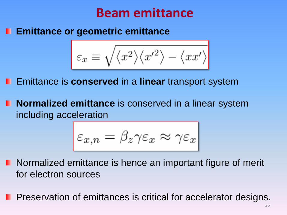
Emittance or geometric emittance
Emittance is conserved in a linear transport system
Normalized emittance is conserved in a linear system
including acceleration
Beam emittance
Normalized emittance is hence an important figure of merit
for electron sources
Preservation of emittances is critical for accelerator designs. 25

Beam optics function Optics functions (Twiss parameters)
Given beta function along beamline
26

Free space propagation
Analogous with Gaussian laser beam
Single particle
Beam envelope
27

Multiple elements (e. g., FODO lattice)
FODO lattice
28

FODO lattice II
Maximum beta
Minimum beta
When f >> l
29

Electron distribution in phase space We define the distribution function F so that
Since the number of electrons is an
invariant function of z, distribution
function satisfies Liouville theorem
equations of motion
is the number of electrons per unit phase space volume
30

Gaussian beam distribution Represent the ensemble of electrons with a continuous
distribution function (e.g., Gaussian in x and x’)
For free space propagation
Distribution in physical space can be obtained by integrating
F over the angle
31

Photon beams
Wave equation and paraxial approximation
Radiation diffraction and emittance
Transverse and temporal coherence
Brightness and diffraction limit
Bright accelerator based photon sources
32
Radiation intensity and bunching

Photon wavelength and energy
33

FEL oscillators
(High-average power)
Single pass FELs
(SASE or seeded)
Synchrotron radiation
Undulator radiation Various accelerator
and non-acc. sources 34

Radiation diffraction Wave propagation in free space
Paraxial approximation (f2 << 1)
General solution
Angular representation
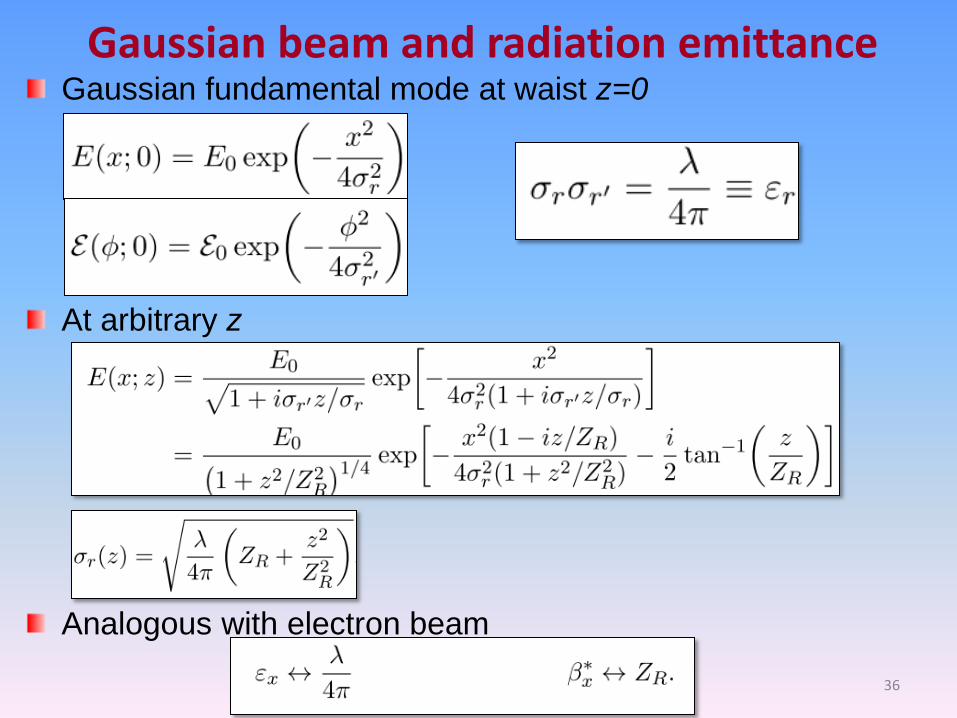
Gaussian beam and radiation emittance
At arbitrary z
Analogous with electron beam
Gaussian fundamental mode at waist z=0
36

What is coherence?
37
Complex degree of coherence
R. Ischebeck
E(x,t) at location z z

Transverse (Spatial) Coherence Transverse coherence can be measured via the interference pattern in Young's double slit experiment.
Near the center of screen, fringe visibility is described by g(x1,x2,0).
Degree of transverse coherence (coherence fraction):
38
D. Attwood

Phase space criteria for transverse coherence
• Initial phase space area 4pR >> l
• Coherent flux is reduced by MT • This criteria from physical optics argument
• Final phase space area
39

Coherence time is determined by measuring the path length difference over which fringes can be observed in a Michelson interferometer.
Temporal (Longitudinal) Coherence
Temporal coherence function and the radiation spectrum forms a Fourier pair
For a Gaussian radiation spectrum,

Temporal Coherence
41

Chaotic light Radiation from many random emitters (Sun, SR, SASE FEL)
Correlation function and coherence time
42

Temporal mode and fluctuation
1
L
W
W M
D
Number of regular temporal regions is # of coherent modes
Intensity fluctuation
Total # of modes
Same numbers of mode in frequency domain
Fourier limit, minimum longitudinal phase space
Longitudinal phase space is ML larger than Fourier limit
43

Due to resonant condition, light overtakes e-beam by one radiation wavelength l1 per undulator period
electron bunch
optical pulse
electron bunch
optical pulse z
Interaction length = undulator length
Slippage length = l1 × undulator period (e. g., 100 m LCLS undulator has slippage length 1.5 fs,
much less than 100-fs e-bunch length)
Each part of optical pulse is amplified by those electrons within a slippage length (an FEL slice)
Only slices with good beam qualities (emittance, current, energy spread) can lase
Projected and slice beam parameters
slippage length
Dz

Light Bulb vs. Laser
A. Schawlow (Nobel prize on laser spectroscopy), Scientific Americans, 1968
Radiation emitted from light bulb is chaotic.
Pinhole can be used to obtain spatial coherence.
Monochromator can be used to obtain temporal coherence.
Pinhole and Monochromator can be combined for coherence.
Laser light is spatially and temporally coherent.

Brightness
D
Dx
Units: photons/s/mm2/mrad2/0.1%BW
2)divergence size (source
unit timein range spectralunit in Photons
B
Peak
Average 46
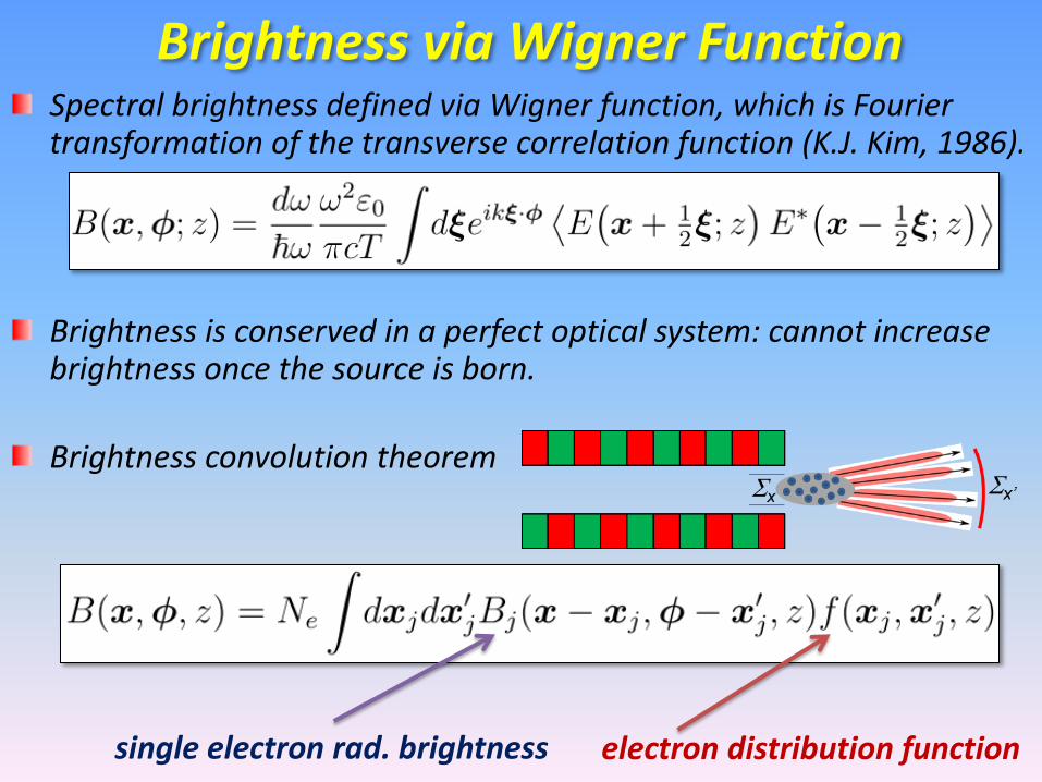
Brightness via Wigner Function Spectral brightness defined via Wigner function, which is Fourier transformation of the transverse correlation function (K.J. Kim, 1986).
Brightness is conserved in a perfect optical system: cannot increase brightness once the source is born.
Brightness convolution theorem
electron distribution function single electron rad. brightness

Radiation from many electrons Such a beam can be described by the convolution of the
coherent Gaussian beam with the electron distribution in
phase space
Same formula as previous slide except sr Sr, sr’ Sr’
When electron beam emittance >>l/(4p)
# of transverse modes
x
x’

Synchrotron Radiation Facilities
State-of-art storage rings have pulse duration ~10 ps, emittance ~1 nm. Diffraction-limited storage rings and energy recovery linacs with emittance ~10 pm
are under active R&D.
SSRF (2009)
MAX-IV (2016)
NSLS-II (2014)

Perfect optical system has dss = dii
i is the numerical aperture of focusing system
i s di ds
Diffraction Limit
p
l
4~~ r
yx
Ultimate spatial resolution
50
Reducing pinhole size until dss ~ l/2
since di ~ l /(2i) reaches diffraction limit.
A even smaller pinhole does not reduce the image size but only hurts the photon flux
Diffraction limited source does not require a pinhole and provide the most coherent flux

Storage Ring Spectral Brightness
B. Hettel 51

When
intensity from many electrons add incoherently (~Ne)
Radiation intensity What if emitters are not random in time
For an electron bunch with rms bunch length se
52

Bunching and coherent radiation
Form factor or bunching factor
If the bunch length is shorter than the radiation wavelength
Radiation intensity from many electrons add coherently
(~Ne2)
Another way to produce bunching from a relatively long
bunch is through so-called microbunching
53

Resonant interaction of electrons
with EM radiation in an undulator^
Free Electron Laser (FEL)
Coherent radiation intensity N2
due to beam microbunching
(N: # of e- involved ~106 to 109)
l1
S. Reiche
At x-ray wavelengths, use Self-Amplified Spontaneous Emission* (a wonderful instability!) to reach high peak power
* Kondradenko, Saldin, Part. Accel., 1980 * Bonifacio, Pellegrini, Narducci, Opt. Com., 1984 ^ J. Madey, J. Appl. Phys., 1971

Evolution of X-ray Light Sources GE synchrotron (1946) opened a new era of accelerator-based light sources.
These light sources have evolved rapidly over four generations.
The first three-generations are based on synchrotron radiation.
The forth-generation light source is a game-changer based on FELs.
The dramatic improvement of brightness and coherence over 60 years easily outran Moore’s law.

X-Ray Holography: Coherence Wanted Lensless imaging of magnetic nanostructures by x-ray holography

Ordered Structures
Equilibrium Phenomena
Disordered Structures
Nonequilibrium Phenomena
Transient States
1900 2000 future
Era of Crystalline Matter Era of Disordered Matter
Coherent X-ray Probes Conventional X-ray Probes
Future Role of FELs and Advanced Sources
H. Dosch (DESY)

58
Summary Despite spectacular successes in synchrotron radiation and FELs, the quest for brightness and coherence continues, with no sign of slowing down.
Future light source development includes diffraction-limited light sources, high-peak and average power FELs, compact coherent sources and many more possibilities.
I hope you enjoy this summer school and this exciting field of research.