basic dc principles for telecommunications tutorial
TRANSCRIPT

8/3/2019 Basic DC Principles for Telecommunications Tutorial
http://slidepdf.com/reader/full/basic-dc-principles-for-telecommunications-tutorial 1/65
Basic DC Principles for Telecommunications
© JB Hunter Technology Page 1 V2.3
Student Tutorial
Basic DC Principles for Telecommunications
This introductory course is designed to assist those who have little or nobackground in electrical terminology and concepts to cope with thetraining modules which are mandatory for obtaining a cabling registrationunder the ACMA’s Cabling Provider Rules.
The DC Principles examination conducted at the end of this course willenable you to evaluate how well you have mastered the instructionalmaterial.
A mark of 80% or more indicates that you have mastered this material
well enough to cope with the mandatory modules which comprise theOpen and Restricted Registration conversion courses for those withindustry cabling experience.
A mark significantly less than 80 % means that you should attend anationally accredited module for more detailed instruction in AC/DCElectrical Principles such as NTE009 or NE160 (or equivalent) beforeattempting the mandatory modules for cabling registration training.
Topics
1. Principles of Electricity2. Electrical Terms and Units3. DC and AC4. Electrical Circuit Components5. Simple Electrical Circuits6. The Telephone Local Loop7. Safety Issues8. Measuring Instruments9. Magnetism and Electro-Magnetism10. Answers to End of Chapter Assessment Questions
8/3/2019 Basic DC Principles for Telecommunications Tutorial
http://slidepdf.com/reader/full/basic-dc-principles-for-telecommunications-tutorial 2/65
Basic DC Principles for Telecommunications
© JB Hunter Technology Page 2 V2.3
Chapter 1 – Principles of Electricity
1.1 Atoms
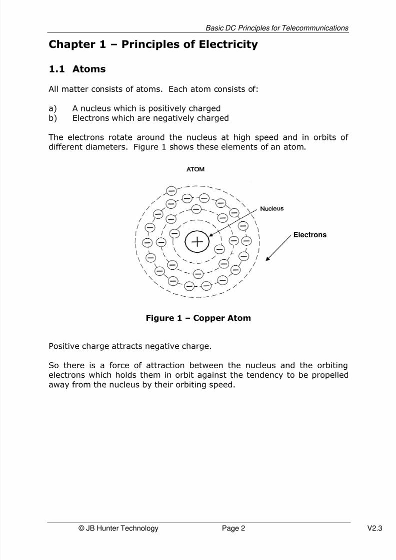
All matter consists of atoms. Each atom consists of:
a) A nucleus which is positively chargedb) Electrons which are negatively charged
The electrons rotate around the nucleus at high speed and in orbits of different diameters. Figure 1 shows these elements of an atom.
Figure 1 – Copper Atom
Positive charge attracts negative charge.
So there is a force of attraction between the nucleus and the orbitingelectrons which holds them in orbit against the tendency to be propelledaway from the nucleus by their orbiting speed.
Electrons
8/3/2019 Basic DC Principles for Telecommunications Tutorial
http://slidepdf.com/reader/full/basic-dc-principles-for-telecommunications-tutorial 3/65
Basic DC Principles for Telecommunications
© JB Hunter Technology Page 3 V2.3
1.2 Conductors
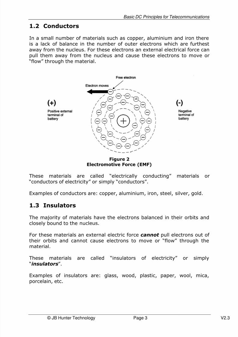
In a small number of materials such as copper, aluminium and iron thereis a lack of balance in the number of outer electrons which are furthestaway from the nucleus. For these electrons an external electrical force canpull them away from the nucleus and cause these electrons to move or “flow” through the material.
Figure 2Electromotive Force (EMF)
These materials are called “electrically conducting” materials or “conductors of electricity” or simply “conductors”.
Examples of conductors are: copper, aluminium, iron, steel, silver, gold.
1.3 Insulators
The majority of materials have the electrons balanced in their orbits andclosely bound to the nucleus.
For these materials an external electric force cannot pull electrons out of their orbits and cannot cause electrons to move or “flow” through thematerial.
These materials are called “insulators of electricity” or simply “insulators”.
Examples of insulators are: glass, wood, plastic, paper, wool, mica,porcelain, etc.

8/3/2019 Basic DC Principles for Telecommunications Tutorial
http://slidepdf.com/reader/full/basic-dc-principles-for-telecommunications-tutorial 4/65
Basic DC Principles for Telecommunications
© JB Hunter Technology Page 4 V2.3
1.4 Semi-Conductors
There is another class of materials which, when they have certainimpurities added to their atomic structure will support “conduction” underparticular electrical conditions. Semiconductor materials are used toproduce transistors and integrated circuits.
Examples of these materials are germanium and silicon.
1.5 Electrical Force or Pressure
The external electrical force or pressure which causes the electrons to bepulled out of orbit and flow in conductors is called an EMF.
EMF stands for electromotive force.
Figure 3Movement of Electrons
A car battery produces an EMF across its terminals due to chemicalreactions occurring inside this “lead-acid” battery.This EMF causes the electron flow in the wires connecting the battery tothe car headlights.
This electron flow through the fine wires of the headlights heats them upto “white” intensity causing them to “light up”.
The “generator” in the car is a source of EMF.The car engine drives the electrical generator which converts rotationalenergy of the car engine into an electrical force or EMF. This EMF isproduced across the output terminals of the generator.
Solar cells produce a small EMF by converting the energy of sunlight into
an electrical pressure or force.
Electric Current Flow
EMF
PositiveTerminal
NegativeTerminal

8/3/2019 Basic DC Principles for Telecommunications Tutorial
http://slidepdf.com/reader/full/basic-dc-principles-for-telecommunications-tutorial 5/65
Basic DC Principles for Telecommunications
© JB Hunter Technology Page 5 V2.3
Steam-driven turbines drive electrical generators to produce large EMFs orelectrical pressures to power up the electrical transmission lines whichdistribute electricity through Australia.
Examples of sources of EMF or electrical pressure are:
• car battery• car (electrical) generator• solar cells
• turbine driven – electrical generators
1.6 Electrical Current
The combined effect of many electrons flowing along a conductor is calledelectrical current flow. Refer to Figure 3.
Electric current flow can generate heat and this effect is used in theelectric radiators and electric light globes. In the case of electric lightglobes the heat is sufficiently intense to heat the light globe’s fine wires towhite heat producing light.
Figure 4An Electric Circuit
Examples of the use of electrical current for heating:
• electric radiator• electric light globe• electric toaster

8/3/2019 Basic DC Principles for Telecommunications Tutorial
http://slidepdf.com/reader/full/basic-dc-principles-for-telecommunications-tutorial 6/65
Basic DC Principles for Telecommunications
© JB Hunter Technology Page 6 V2.3
1.7 Assessment Questions
1. Positive and negative charges:
a) Attract each otherb) Repel each other
c) Have no interaction with each other
2. The positive battery terminal
a) Repels electronsb) Attracts electronsc) Has no interaction with electrons
3. Name three conductors of electricity:
a) _________________________
b) _________________________
c) _________________________
4. Name three insulators of electricity:
a) _________________________
b) _________________________
c) _________________________
5. Name two semi-conductor materials:
a) _________________________
b) _________________________
6. What does the abbreviation, “EMF” mean?
___________________________________________________
7. What is another way of describing “EMF”?
___________________________________________________

8/3/2019 Basic DC Principles for Telecommunications Tutorial
http://slidepdf.com/reader/full/basic-dc-principles-for-telecommunications-tutorial 7/65
Basic DC Principles for Telecommunications
© JB Hunter Technology Page 7 V2.3
8. State three sources of EMF:
a) _________________________
b) _________________________
c) _________________________
9. Complete this sentence:
An electrical current is ________________________________
10. Provide two examples of home appliances which use the heatingeffect of electrical current flow:
a) _________________________
b) _________________________

8/3/2019 Basic DC Principles for Telecommunications Tutorial
http://slidepdf.com/reader/full/basic-dc-principles-for-telecommunications-tutorial 8/65
Basic DC Principles for Telecommunications
© JB Hunter Technology Page 8 V2.3
Chapter 2 – Electrical Terms and Measurement
Units
2.1 Electrical Pressure (EMF)
• Electrical pressure or EMF is measured in volts.• The symbol “v” is used for voltage.• A high voltage would be a voltage greater than 1500 volts (written
as 1500v).• A low voltage would be a voltage less than 1500 v but greater than
about 60v.• Extra-low voltage would be less than 60v.
Electrical power is generally delivered to the home at 240v.
Home appliances are designed to be powered up by 240v. Even thoughthis level of electrical pressure is called “low voltage” it can still kill you.
Safety aspects of dealing with electricity are dealt with in section7.
A 12v car battery is in the extra-low voltage category and under normalconditions is of no danger to humans.
2.2 Electrical Current
Electrical current flow is measured in amperes (generally called “amps” forshort). The symbol used for amps is “I”.
A 1000/2000 watt/240v domestic electric radiator “draws” between 5 Aand 10 A of electric current.
A 100 watt/240v electric light globe draws about 0.5 A of electric current.
Your telephone draws about 0.05 A of electrical current from the
telephone exchange via the telephone line.

8/3/2019 Basic DC Principles for Telecommunications Tutorial
http://slidepdf.com/reader/full/basic-dc-principles-for-telecommunications-tutorial 9/65
Basic DC Principles for Telecommunications
© JB Hunter Technology Page 9 V2.3
2.3 Electrical Resistance
The ease with which electrons are pulled out of their orbits in conductorsvaries with the material.
The electrons are more easily pulled out of their orbits in copper than iniron. So copper has a lower “resistance” to having electrons pulled out of their orbit than iron.
So we say that copper has a lower electrical resistivity (“resistance”) thaniron.Aluminium has a lower resistivity than iron but not as low as copper.
The following list of conductors is in resistivity order with the lowestresistivity materials first and the highest, last:
• Silver (lowest)• Copper• Gold• Aluminium• Tungsten• Platinum• Steel• Nichrome (highest)
So, on this listing of conductors, silver is the best conductive material with
the lowest resistivity and nichrome is the poorest conductive material withthe highest resistivity.
2.4 Electrical Resistance of a Conductor
In electrical work, electrical components like a battery and car headlightsare connected together using conductors consisting of lengths of copperwire. These wires have a layer of insulation material covering them.
The telephone is electrically connected to the telephone exchange using
insulated copper wires.
The light switches in your home are electrically connected to the lightsand power points by conductors such as lengths of insulated wire.
The connecting wires in electrical work are a vital part of the installationsand we need to understand their important properties.
One of their most important properties is their electrical resistance.
This is the total resistance to electrical current flow from one end of a wireto the other end.

8/3/2019 Basic DC Principles for Telecommunications Tutorial
http://slidepdf.com/reader/full/basic-dc-principles-for-telecommunications-tutorial 10/65
Basic DC Principles for Telecommunications
© JB Hunter Technology Page 10 V2.3
This total resistance is determined by:
a) the length of the wire: the longer the wire the greater the overallresistance
b) the type of material used in the wire : this is its resistivity c) the cross-sectional area of the wire: larger diameter wires have
less resistance than smaller diameter wires. You could compare histo water pipes where large diameter pipes have less resistance towater flow than small diameter pipes
d) temperature: where the environment temperature is high, theresistance will be higher than in a lower temperature environment
Electrical resistance is measured in ohms. The symbol used for ohms is “Ω”.
The following table compares the resistance of 100 m lengths of copper
wire for various wire diameters (cross-sectional areas). The wirediameters chosen in the table are typical of those used in telephony anddata work.The resistance values apply for a temperature of 20 °°°°C.
WireDiameter
Cross-Sectional Areain mm2
ResistancePer 100 m
Typical Uses
0.4 mm 0.126 14 Ω Telecommunications external distributioncables
0.5 mm 0.196 9 Ω Internal building telephone and data cables
and some telecommunications externalcables
0.64 mm 0.32 5.4 Ω Longer distance telecommunications external
cables
7/0.67mm(7 strands of 0.67 diawire)
2.5 0.7 Ω Earthing of metal work and distributionframes in telecommunications/ datainstallations but not for lightning protectionearthing
7/1.04 mm(7 strands of 1.04 mmdia)
6 0.3 Ω Lightning protection earthing intelecommunications installations in buildings
Table 1Typical Resistances of Copper Wire at 20 °°°°C for 100m Length

8/3/2019 Basic DC Principles for Telecommunications Tutorial
http://slidepdf.com/reader/full/basic-dc-principles-for-telecommunications-tutorial 11/65
Basic DC Principles for Telecommunications
© JB Hunter Technology Page 11 V2.3
2.5 How Temperature changes Resistance
Conducting materials such as copper, aluminium and steel have a positivetemperature co-efficient.
This means that as the temperature increases, their resistance increasesalso.
So a 100 metres length of copper wire at 45 °C will have a higher
resistance than the same length of wire at 20 °C.
The temperature co-efficient for copper is 0.00393 ohms per ohm per °C.
Example: A copper wire has a resistance of 10 ohms at 20 °°°°C.
Calculate its new resistance at 45 °°°°C.The change in temperature is (45 – 20) = 25 °°°°C.
At 40 °°°°C its resistance will be:
10 + 0.00393 X 10 X (25)= 10 + 0.983= 10.983 ohms

8/3/2019 Basic DC Principles for Telecommunications Tutorial
http://slidepdf.com/reader/full/basic-dc-principles-for-telecommunications-tutorial 12/65
Basic DC Principles for Telecommunications
© JB Hunter Technology Page 12 V2.3
2.6 Assessment Questions
1. The unit of measurement of EMF is the ___________ and its
symbol is ___________
2. Complete the following:
a) High voltage is above _____________
b) Extra low voltage is below _________
c) Low voltage is below __________ but above __________
3. In which of the voltage categories mentioned in Question 2 wouldyou place a 12v car battery?
____________________________
4. In which of the voltage categories mentioned in Question 2 wouldyou place the voltage output of the three pin power socket in yourhome?
____________________________
5. The unit of measurement of electric current is the ___________ and
its symbol is ___________
6. Which material is the better conductor of electricity –Silver, iron, mica, plastic or copper?
____________________________
9. Of the following conductor material, which material has the highestresistivity Copper, gold, platinum, aluminium or nichrome?
____________________________

8/3/2019 Basic DC Principles for Telecommunications Tutorial
http://slidepdf.com/reader/full/basic-dc-principles-for-telecommunications-tutorial 13/65
Basic DC Principles for Telecommunications
© JB Hunter Technology Page 13 V2.3
10. The resistance of a conducting wire is determined by:
a)___________________________
b)___________________________
c)___________________________
d)___________________________
11. A copper wire of 0.4 mm diameter is 100 metres long and has aresistance of 14 . If the same type of wire was 200 metres longwould its resistance be:
a) greater than 14 b) less than 14
c) the same if the temperature was the same
12. Which would have the greater resistance:
a) 100m length of copper wire of 0.4 mm diameterb) 100 m length of copper wire of 0.5 mm diameterc) 100 m length of copper wire of 0.64 mm diameter
12. If a 50 m length of copper wire of 0.5 mm diameter has a resistanceof 7 when the temperature is 20 ºC, would its resistance be
greater or less than 7 when the temperature rises to 40 ºC?
a) Greater than 7 b) Less than 7
8/3/2019 Basic DC Principles for Telecommunications Tutorial
http://slidepdf.com/reader/full/basic-dc-principles-for-telecommunications-tutorial 14/65
8/3/2019 Basic DC Principles for Telecommunications Tutorial
http://slidepdf.com/reader/full/basic-dc-principles-for-telecommunications-tutorial 15/65
Basic DC Principles for Telecommunications
© JB Hunter Technology Page 15 V2.3
• Most modern cars use an AC electrical generator which has anoutput voltage of 12 v ac.
• The electric motor which drives the domestic refrigerator’s coolingsystem is a 240 v ac motor.
• The lighting and power distribution in a home is a 240 v ac system.
This ac current alternates 50 times a second. We say this ac current has a “frequency” of 50 hertz (50 Hz for short).
When you speak into a telephone, the transmitter converts your voicesound signals into alternating current signals for transmission down thetelephone line. These signals are extra low voltage and are approximately1-2v ac.

8/3/2019 Basic DC Principles for Telecommunications Tutorial
http://slidepdf.com/reader/full/basic-dc-principles-for-telecommunications-tutorial 16/65
Basic DC Principles for Telecommunications
© JB Hunter Technology Page 16 V2.3
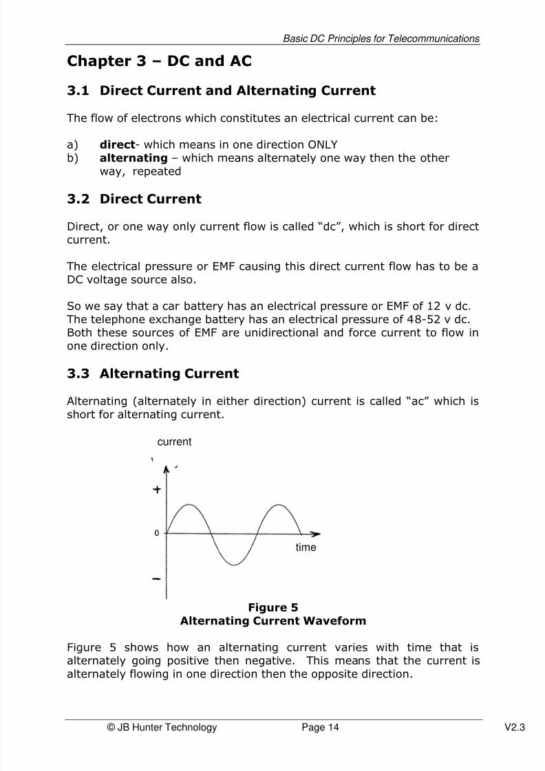
3.4 Assessment Questions
1. What is meant by the abbreviation “dc”?
____________________________________________________
2. What does the abbreviation “ac” represent?
____________________________________________________
3. Does a car battery produce dc or ac?
___________________________
4. Is the home lighting and power distribution dc or ac?
___________________________
5. When you speak into a telephone, its transmitter converts yourvoice signals into electrical signals. Are these converted signals acor dc?
___________________________
6. What is the voltage level of the telephone exchange battery anddoes it produce ac or dc?
___________________________

8/3/2019 Basic DC Principles for Telecommunications Tutorial
http://slidepdf.com/reader/full/basic-dc-principles-for-telecommunications-tutorial 17/65
Basic DC Principles for Telecommunications
© JB Hunter Technology Page 17 V2.3
Chapter 4 – Electrical System Components
4.1 Components
The building blocks of electrical systems including those used in
telecommunications systems include:
a) Sources of EMF ( electrical pressure)b) The wires or cables connecting the system components together to
form an electrical current pathc) Resistorsd) Capacitorse) Switches
4.2 Sources of EMF (Electrical Pressure)
In telecommunications systems, the telephone exchange battery is amajor and common source of DC voltage to power the telephones whichare connected to it. This battery consists of individual cells each having aterminal voltage of approximately 2 volts. 24 of these are connected intandem to give an overall EMF of 48-52 v dc
Figure 6 shows the circuit symbol for a single cell of a battery and thesymbol for a number of cells combined in tandem.
Figure 6 – Circuit Symbols for Battery Cells
a) Symbol for single cellshowing positive andnegative terminals
b) Symbol for two cells intandem (series) showingpositive and negative
c) Symbol for multiple cells connected intandem (series) showing positive andnegative terminals

8/3/2019 Basic DC Principles for Telecommunications Tutorial
http://slidepdf.com/reader/full/basic-dc-principles-for-telecommunications-tutorial 18/65
Basic DC Principles for Telecommunications
© JB Hunter Technology Page 18 V2.3
Solar cells energised by sunlight are used to provide the EMF to remotetelecommunications equipment. Typically, a composite cell array wouldprovide terminal voltages of 12 v dc or 24 v dc.
At the customer’s premises, telecommunications equipment, other thanthe standard telephone, is generally powered by the domestic 240 v ac
source. The power pack which is plugged into a standard three pin poweroutlet may convert the 240 v ac into say 9 or 12 v dc to powertelecommunications equipment such as modems and answering machines.
4.3 Wires and Cables
Conductors connect together electrical/telecommunications equipment tofacilitate electrical current flow between them. These conductors aremanufactured as thin conductors (wires) with an insulation jacket over theoutside of the wire. The insulation material may be PVC (poly-vinyl-
chloride) for indoor wires and polyethylene for outside plant wires. Thewires are associated (generally by twisting them together) into groups of “pairs”. Each pair consists of two wires twisted together and with adistinctive colour code to enable identification of the individual wire and todistinguish each pair from the other pairs.
The insulated pairs of wires are given a further protective coating byenclosing them in a PVC or polyethylene jacket. We call this jacketedassembly of pairs of wires a cable.
Figure 7UTP – Unshielded Twisted Pair
(4 Pair Cable)
Insulated Conductors TwistedTogether to Form Pairs
Overall
Protective Jacket
Individual Bare
Conductors

8/3/2019 Basic DC Principles for Telecommunications Tutorial
http://slidepdf.com/reader/full/basic-dc-principles-for-telecommunications-tutorial 19/65
Basic DC Principles for Telecommunications
© JB Hunter Technology Page 19 V2.3
4.4 Resistors
4.4.1
A resistor is a component through which current flows but which exhibitsconcentrated resistance to the current flow. In some telecommunicationssystems, there is a need to restrict current flow or control current flow byadding “resistance” at a particular point in the system.
The unit of resistance is the “ohm” with the symbol “Ω”.Resistors come in a wide range of physical sizes and packages and a widerange of resistance values. Figure 8 shows examples of resistors.
Figure 8Three Types of Resistor
a) Wire Wound Resistor
b) Carbon Resistor
c) Metal Film Resistor

8/3/2019 Basic DC Principles for Telecommunications Tutorial
http://slidepdf.com/reader/full/basic-dc-principles-for-telecommunications-tutorial 20/65

8/3/2019 Basic DC Principles for Telecommunications Tutorial
http://slidepdf.com/reader/full/basic-dc-principles-for-telecommunications-tutorial 21/65
Basic DC Principles for Telecommunications
© JB Hunter Technology Page 21 V2.3
Figure 10Examples and Relative Sizes of Power Resistors
This power dissipated is obtained by multiplying the voltage applied to the
resistor by the current flow through it, giving the power dissipated inwatts:
V x I = W
Where V = voltage applied to the resistor in voltsI = current flow through it in ampsW = power dissipated in the resistor in watts
8/3/2019 Basic DC Principles for Telecommunications Tutorial
http://slidepdf.com/reader/full/basic-dc-principles-for-telecommunications-tutorial 22/65
Basic DC Principles for Telecommunications
© JB Hunter Technology Page 22 V2.3
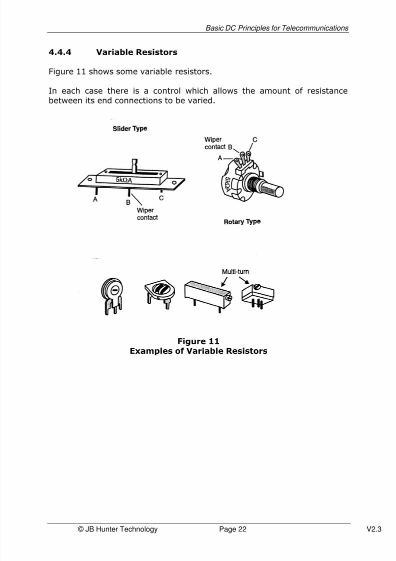
4.4.4 Variable Resistors
Figure 11 shows some variable resistors.
In each case there is a control which allows the amount of resistance
between its end connections to be varied.
Figure 11Examples of Variable Resistors

8/3/2019 Basic DC Principles for Telecommunications Tutorial
http://slidepdf.com/reader/full/basic-dc-principles-for-telecommunications-tutorial 23/65
Basic DC Principles for Telecommunications
© JB Hunter Technology Page 23 V2.3
4.4.5 Drawing symbol for resistor
In electrical/telecommunications drawings a physical symbol is used torepresent a resistor. Figure 12. Shows the drawing symbols used torepresent both fixed and variable resistor elements.
Figure 12Circuit Symbols for Fixed and Variable 10kΩΩΩΩ Resistors
4.5 Capacitors
Capacitors can be used to store small amounts of electricity and as suchhave a “smoothing out” role in certain types of power supplies. They alsohave other roles in electrical and telecommunications systems.
Two important roles of capacitors in telecommunications are:
a) to block direct current (dc)b) to allow alternating current (ac) to pass through
In these roles they discriminate between the two types of current flow,stopping one and allowing the other to pass.
This is very important in the operation of the telephone.
When the telephone is not in use, a capacitor in the phone is placed in thepath of an incoming phone call.
This capacitor blocks the 52v dc exchange voltage from passing throughinto the telephone but allows the ac ring tone to pass through and operatethe ring generator. This ring generator emits the recognisable sound totell you that there is a call for you to answer.
If the capacitor was not there, the telephone would be drawing continuousdc current from the telephone exchange even when the phone was not inuse. This would be a waste of electrical energy.

8/3/2019 Basic DC Principles for Telecommunications Tutorial
http://slidepdf.com/reader/full/basic-dc-principles-for-telecommunications-tutorial 24/65
Basic DC Principles for Telecommunications
© JB Hunter Technology Page 24 V2.3
Examples of capacitor shapes are shown in Figure 13 (a).
The symbol for a fixed capacitor is shown in Figure 13 (b).
The circuit symbol for a capacitor is shown in Figure 13 (c).
Figure 13 (a) Capacitor Shapes
Figure 13 (b) Fixed Disc Capacitors
Figure 13 (c) Circuit Symbol for a Capacitor

8/3/2019 Basic DC Principles for Telecommunications Tutorial
http://slidepdf.com/reader/full/basic-dc-principles-for-telecommunications-tutorial 25/65
Basic DC Principles for Telecommunications
© JB Hunter Technology Page 25 V2.3
4.6 Switches
A switch is a physical circuit component which can either completely stopthe flow of electrical current, or if operated, can allow through the flow of electrical current without any impediment.
Figure 14Controlling Role of Switch in a Simple Installation
The switch position for allowing current through is called the “closed” or “make” position.
The switch position for stopping the flow of current is called the “open” or “break” position.
The symbols for a switch in closed (make) and in open (break) positions,are shown below.
(a) switch closed (b) switch open(make position) (break position)
Figure 15 – Switch Symbols for Open and Closed Positions
The electric light switch is in the “make” position when you switch thelight on” and in the “break” position when you switch the light off.
8/3/2019 Basic DC Principles for Telecommunications Tutorial
http://slidepdf.com/reader/full/basic-dc-principles-for-telecommunications-tutorial 26/65
Basic DC Principles for Telecommunications
© JB Hunter Technology Page 26 V2.3
4.7 Assessment Questions
1. Name three sources of EMF?
a) ____________________________
b) ____________________________
c) ____________________________
2. Draw the circuit symbol for a battery “cell”
3. Draw the battery symbol for multiple cells such as the telephoneexchange battery and indicate its terminal voltage.
4. A wire used for conduction of electricity is a conductor covered ininsulation material. Different insulation materials are used for indoorand outdoor wires/cables. State the insulation material used andwhether used indoor or outdoor.
a) For indoor, the insulation material is
______________________
b) For outdoor, the insulation material is
______________________

8/3/2019 Basic DC Principles for Telecommunications Tutorial
http://slidepdf.com/reader/full/basic-dc-principles-for-telecommunications-tutorial 27/65
Basic DC Principles for Telecommunications
© JB Hunter Technology Page 27 V2.3
5. Draw a diagram showing the parts of a cable used fortelephone/data connections and label those parts.
6. State the unit of resistance and its symbol.
a) The unit of resistance is the ___________
b) The symbol for the unit of resistance is __________
7. State the meaning of “kilo” when used in describing the magnitudeof resistance:
“kilo” means __________________
8. What does 10 MΩ mean ?
_____________________________
9. Draw the symbol for a fixed resistor.
10. Draw the symbol for a variable resistor
8/3/2019 Basic DC Principles for Telecommunications Tutorial
http://slidepdf.com/reader/full/basic-dc-principles-for-telecommunications-tutorial 28/65
Basic DC Principles for Telecommunications
© JB Hunter Technology Page 28 V2.3
11. Draw the symbol for a capacitor
12. State two functions of a capacitor in telephone systems.
a) ____________________________________________________
b) ____________________________________________________
13. Draw the symbol for a switch in the closed (make) position.
14. Draw the symbol for a switch in the open (break) position

8/3/2019 Basic DC Principles for Telecommunications Tutorial
http://slidepdf.com/reader/full/basic-dc-principles-for-telecommunications-tutorial 29/65
Basic DC Principles for Telecommunications
© JB Hunter Technology Page 29 V2.3
Chapter 5 – Electric Circuits
5.1 Circuits
When electrical components are connected together using conductors to
form a closed loop, that assembly is called an electric circuit.
For current to flow around the circuit, there must be a source of EMF(electrical pressure) in the circuit.The electrical pressure then forces current flow around the circuit throughthe electrical components.
A typical electric circuit might consist of a battery, a switch, connectingwires and a lamp.
This is shown in Figure 16.
Figure 16
Typical Electric Circuit
Referring to Figure 16, when the switch is closed, that is in the “make” position, there is a completed circuit and current will flow from one side of the battery, through the switch, around the circuit and through the lampand back to the opposite terminal of the battery.
Referring to the same figure, if the switch is opened, that is, in the “break:” position, the circuit will no longer be complete and current flowwill stop.
5.2 Current Direction
Whilst electric current flow in this type of circuit is comprised of electronflow and is therefore from the negative terminal of the battery, throughthe circuit to the positive terminal of the battery, convention describescurrent flow from positive to negative.
Using the conventional direction does not make any installations orcalculations invalid.
We will use the conventional direction hereafter in this training manual.

8/3/2019 Basic DC Principles for Telecommunications Tutorial
http://slidepdf.com/reader/full/basic-dc-principles-for-telecommunications-tutorial 30/65
Basic DC Principles for Telecommunications
© JB Hunter Technology Page 30 V2.3
5.3 Calculating Current Flow
Referring to Figure 17, we will calculate the current flow in the circuit.
Figure 17
There is a simple formula that allows us to calculate current flow in thiscircuit.
The formula is: I = V ÷ R
That is, the current around the circuit is the voltage applied to the circuitdivided by the total resistance of the circuit.
In Figure 17, the voltage applied to the circuit is 12 volts, and the totalresistance is 6 ohms.
I = V ÷ R
I =12 ÷ 6I = 2 amps. A current of 2 amps will flow through the circuit.
Let’s make the EMF source a 24v battery. What be the current flow nowaround the circuit?
I = V ÷ RI = 24 ÷ 6I = 4 amps.
You will notice that as the EMF is increased, so the current is increased.
Now we will increase the resistance from 6 ohms to 12 ohms and leavethe EMF at 12v.
I = V ÷ RI = 12 ÷ 12I = 1 amp.
Note that an increase in resistance results in a decrease in current.
12 v6 Ω
I in am s

8/3/2019 Basic DC Principles for Telecommunications Tutorial
http://slidepdf.com/reader/full/basic-dc-principles-for-telecommunications-tutorial 31/65
Basic DC Principles for Telecommunications
© JB Hunter Technology Page 31 V2.3
This formula is called “Ohms Law ” and it is a very fundamental formula inelectrical work. In topic 6 you will do basic telephone network calculationsusing ohms law.
5.4 Ohm’s Law
Ohm’s Law is probably the most important electrical relationship you willencounter. It is the basic law of current flow.
A German physicist, Georg Simon OHM (1787 – 1854) discovered thisrelationship in 1827.
When an emf is applied to a resistor a movement of charges is produced.The rate of movement of those charges (current) is directly related to theapplied voltage. If the applied voltage is double, then the current is alsodoubled provided the resistance remains constant.
Ohm’s Law is expressed by:
Resistance = V ÷ I
The resistance is constant as long as the temperature is held constant.
It is important to realise that there are components which haveresistance, but do not obey Ohm’s Law. For example, diodes, lightdependent resistors, and temperature dependent resistors.
8/3/2019 Basic DC Principles for Telecommunications Tutorial
http://slidepdf.com/reader/full/basic-dc-principles-for-telecommunications-tutorial 32/65
Basic DC Principles for Telecommunications
© JB Hunter Technology Page 32 V2.3
V
I R
12 v 10 Ω
1.2 am s
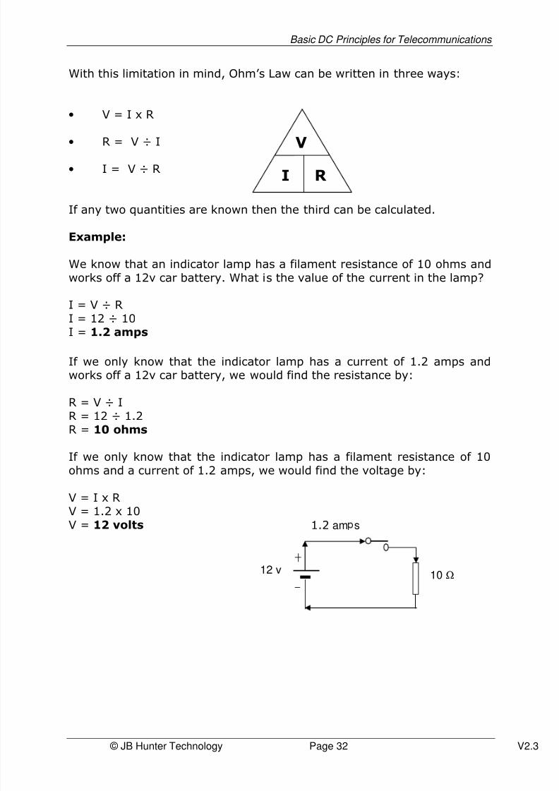
With this limitation in mind, Ohm’s Law can be written in three ways:
• V = I x R
• R = V ÷ I
• I = V ÷ R
If any two quantities are known then the third can be calculated.
Example:
We know that an indicator lamp has a filament resistance of 10 ohms and
works off a 12v car battery. What is the value of the current in the lamp?
I = V ÷ RI = 12 ÷ 10I = 1.2 amps
If we only know that the indicator lamp has a current of 1.2 amps andworks off a 12v car battery, we would find the resistance by:
R = V ÷ I
R = 12 ÷ 1.2R = 10 ohms
If we only know that the indicator lamp has a filament resistance of 10ohms and a current of 1.2 amps, we would find the voltage by:
V = I x RV = 1.2 x 10V = 12 volts

8/3/2019 Basic DC Principles for Telecommunications Tutorial
http://slidepdf.com/reader/full/basic-dc-principles-for-telecommunications-tutorial 33/65
Basic DC Principles for Telecommunications
© JB Hunter Technology Page 33 V2.3
5.5 Series Circuits
When electrical components are connected in tandem to form a closedloop, the circuit components are said to be connected in series.
Figure 18Series Circuit
Going around the circuit starting at the positive terminal of the batteryand proceeding to the negative terminal of the battery, we have:
100 ohm resistor, 600 ohm resistor and a 100 ohm resistor.
These components are said to be connected in series. The circuit iscompleted through the battery. We call this circuit a “ series circuit ”.
The total resistance in this circuit as “seen” by the battery is the sum of the individual resistances; ie 100 + 600 + 100 = 800 Ω
5.6 Parallel Circuits
When electrical components are connected across each other, that is thecomponents divide the circuit into more than one path it is said to be a parallel circuit.
In this circuit the current, I, from the battery will now divide between thetwo resistors. The resistors are regarded as being in parallel.A parallel connection is present when the components divide the current.
12 v
I in amps100 Ω
100 Ω
600 Ω

8/3/2019 Basic DC Principles for Telecommunications Tutorial
http://slidepdf.com/reader/full/basic-dc-principles-for-telecommunications-tutorial 34/65
Basic DC Principles for Telecommunications
© JB Hunter Technology Page 34 V2.3
The parallel circuits will provide extra current paths and hence a largeroverall current. It is therefore reasonable to expect less total resistancefor an increase in total current. This can be proved as follows.
Using Ohm’s Law:
I1 = V1 ÷ R1
I2 = V2 ÷ R2
IT = VS ÷ RT
Where RT is used to represent the total resistance.
8/3/2019 Basic DC Principles for Telecommunications Tutorial
http://slidepdf.com/reader/full/basic-dc-principles-for-telecommunications-tutorial 35/65
Basic DC Principles for Telecommunications
© JB Hunter Technology Page 35 V2.3
200Ω 200Ω
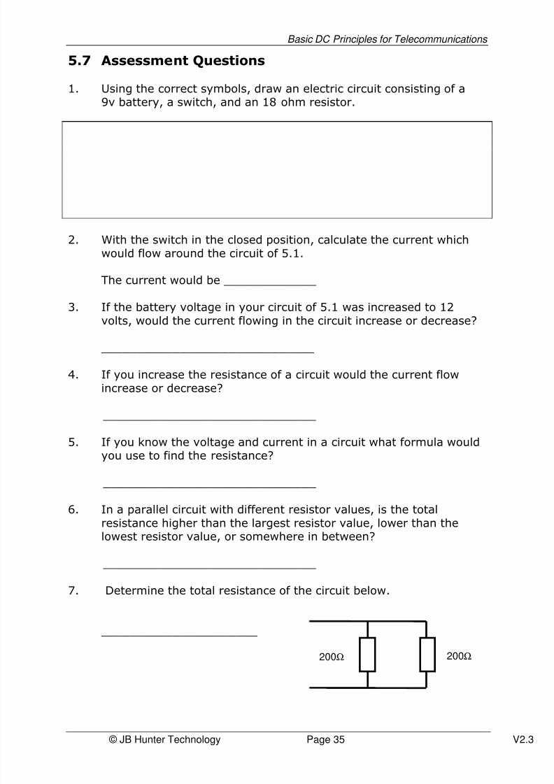
5.7 Assessment Questions
1. Using the correct symbols, draw an electric circuit consisting of a9v battery, a switch, and an 18 ohm resistor.
2. With the switch in the closed position, calculate the current whichwould flow around the circuit of 5.1.
The current would be _____________
3. If the battery voltage in your circuit of 5.1 was increased to 12volts, would the current flowing in the circuit increase or decrease?
______________________________
4. If you increase the resistance of a circuit would the current flowincrease or decrease?
______________________________
5. If you know the voltage and current in a circuit what formula wouldyou use to find the resistance?
______________________________
6. In a parallel circuit with different resistor values, is the totalresistance higher than the largest resistor value, lower than thelowest resistor value, or somewhere in between?
______________________________
7. Determine the total resistance of the circuit below.
______________________

8/3/2019 Basic DC Principles for Telecommunications Tutorial
http://slidepdf.com/reader/full/basic-dc-principles-for-telecommunications-tutorial 36/65
Basic DC Principles for Telecommunications
© JB Hunter Technology Page 36 V2.3
Chapter 6 – The Local (Telephone) Loop
6.1 The CAN and the Local Loop
The connection between your fixed telephone at home and the telephone
exchange is called the “local loop”. It is also called the customer’s accessconnection as it gives you access to the switching and transmissionnetwork of the carrier with whom you are associated.
The aggregate of all the telephone connections from home to telephoneexchange is called, collectively, the Customer’s Access Network or “CAN” for short. Electrically, this “local loop” looks like the circuit in Figure 19.
Figure 19Local Loop Telephone Circuit
Note that the circuit consists of a battery, a pair of wires and a resistorrepresenting the telephone resistance, at the opposite end of the “telephone line”. We show a resistor in each of the connecting wires toremind us that each length of wire has resistance. This is a series circuit.
The source of EMF is the telephone exchange battery of 48-52 volts.We will use the upper figure of 52 volts in our calculations.
Each wire in the pair of wires connecting this battery to the telephone inyour home, will have resistance. The amount of resistance in the total
length of each wire will depend on:
a) its actual lengthb) it diameter (cross-sectional area)c) its material (copper in this case).
A typical wire used in this situation would have a diameter of 0.4 mm anda resistance of 14 per 100 metres.
We will make the connecting cable distance 1 km from the telephone
exchange to the home telephone.
Each connecting wire will have a resistance of 14 x 1000 ÷ 100 =140.
8/3/2019 Basic DC Principles for Telecommunications Tutorial
http://slidepdf.com/reader/full/basic-dc-principles-for-telecommunications-tutorial 37/65
Basic DC Principles for Telecommunications
© JB Hunter Technology Page 37 V2.3
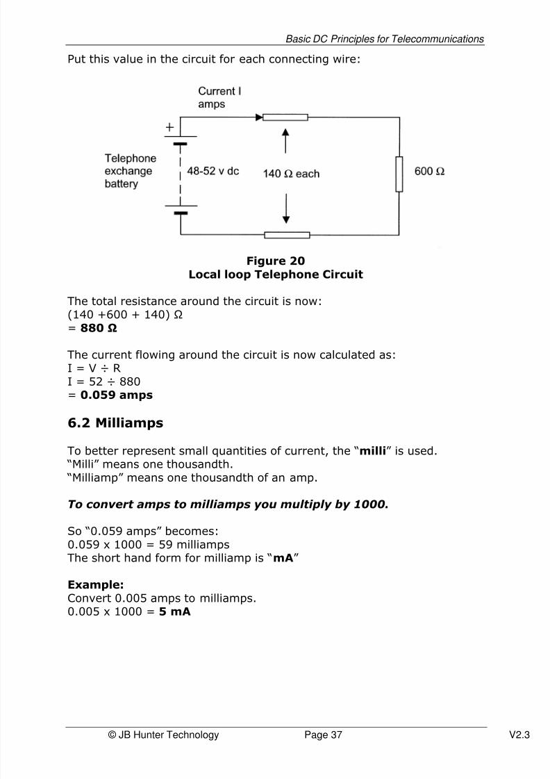
Put this value in the circuit for each connecting wire:
Figure 20
Local loop Telephone Circuit
The total resistance around the circuit is now:(140 +600 + 140) = 880
The current flowing around the circuit is now calculated as:I = V ÷ RI = 52 ÷ 880= 0.059 amps
6.2 Milliamps
To better represent small quantities of current, the “milli” is used. “Milli” means one thousandth. “Milliamp” means one thousandth of an amp.
To convert amps to milliamps you multiply by 1000.
So “0.059 amps” becomes:
0.059 x 1000 = 59 milliampsThe short hand form for milliamp is “mA”
Example:Convert 0.005 amps to milliamps.0.005 x 1000 = 5 mA

8/3/2019 Basic DC Principles for Telecommunications Tutorial
http://slidepdf.com/reader/full/basic-dc-principles-for-telecommunications-tutorial 38/65
Basic DC Principles for Telecommunications
© JB Hunter Technology Page 38 V2.3
6.3 Another Local Loop Calculation
Increase the distance from the telephone exchange to the home telephoneto 2.5 km. Using 0.4 mm diameter copper wire and 52 volts for theexchange battery, calculate the current flow in the local loop circuit.Remember this wire has a resistance of 14 ohms for every 100m length of wire.
Each connecting wire will now have a resistance of:14 x 2,500 ÷ 100= 350
The total resistance for the circuit will now be:= 350 + 600 + 350= 1300
The circuit is as shown in Figure 21.
Figure 21Local Loop Telephone Circuit
The current flow around the circuit will now be:I = 52 ÷ 1300= 0.04 amp.Converting to milliamps:0.04 x 1000= 40 mA

8/3/2019 Basic DC Principles for Telecommunications Tutorial
http://slidepdf.com/reader/full/basic-dc-principles-for-telecommunications-tutorial 39/65
Basic DC Principles for Telecommunications
© JB Hunter Technology Page 39 V2.3
6.4 Assessment Questions
1. State the meaning of the abbreviation “mA”?
“mA” means ___________________
2. Convert 0.03 Amps to milliamps
0.03 Amps = _________ milliamps
3. Convert 0.005 A to mA.
0.005 A = _______ mA
4. Examine the Figure below. What is the total resistance between thetwo battery terminals going around the circuit clockwise?
The total resistance is ____________________________
5. Calculate the current flow around the circuit of the figure shown inquestion 4.
I = _______ mA
20052 v dc

8/3/2019 Basic DC Principles for Telecommunications Tutorial
http://slidepdf.com/reader/full/basic-dc-principles-for-telecommunications-tutorial 40/65
Basic DC Principles for Telecommunications
© JB Hunter Technology Page 40 V2.3
Chapter 7 – Electrical Safety Matters
7.1 An Electric Shock can be Painful and Fatal
About 100 people die each year in Australia from electric shock.
Before touching electrical components or installing electrical componentsand circuits or maintaining them, it is essential to understand:
a) What constitutes electric shock?b) How is the body affected by electricity?c) How can you avoid electric shock; what precautions must be taken
to avoid the risk of electric shock?d) What to do if someone else is subject to electric shock?
7.2 Effects on the Human Body
Figure 22Physiological Effect
The physiological effect of electricity on the human body can vary from a “tingling” sensation which has no lasting effects to the stopping of theheat beat and breathing. Depending on the duration and severity, thislatter physiological effect may result in death.
Voltages as low as 24 v may cause the “tingling” sensation but this levelof voltage is normally consider non-lethal and in fact voltages up to 60 vdc and 42.4 v ac (peak) are generally considered non-lethal.
Voltage greater than these are considered potentially lethal.
It is the passage of electric current through the body and which mayinterfere with the nervous system which causes the problem for humans.

8/3/2019 Basic DC Principles for Telecommunications Tutorial
http://slidepdf.com/reader/full/basic-dc-principles-for-telecommunications-tutorial 41/65
Basic DC Principles for Telecommunications
© JB Hunter Technology Page 41 V2.3
Voltage simply breaks down the skin resistance to allow current to flowthrough the body.
Once the skin resistance has been broken down, the body fluid pathspresent low resistance paths to the electric current.
Current will enter the body at one point of contact and leave it at anotherpoint of contact in the external electrical path with current flow throughthe body between these two points.
Figure 23The Effect of an Electric Shock
Figure 23 shows two situations.
The first (a) shows the points of contact being fingers on the one hand.Current flowing between these two points (one finger to the other on thesame hand) is not so serious as Figure (b). Figure (b) shows the points of contact being the two hands with current flowing through body andpossible via the heart. This is a serious situation as the heart’s nervoussystem may therefore be directly affected.
Quite small amount of current may have a major effect on the humanbody.
8/3/2019 Basic DC Principles for Telecommunications Tutorial
http://slidepdf.com/reader/full/basic-dc-principles-for-telecommunications-tutorial 42/65
Basic DC Principles for Telecommunications
© JB Hunter Technology Page 42 V2.3
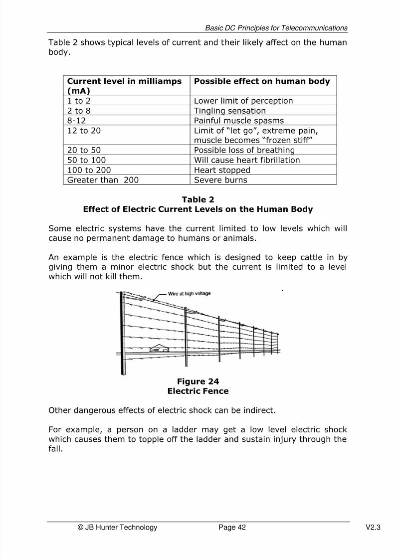
Table 2 shows typical levels of current and their likely affect on the humanbody.
Current level in milliamps(mA)
Possible effect on human body
1 to 2 Lower limit of perception2 to 8 Tingling sensation
8-12 Painful muscle spasms
12 to 20 Limit of “let go”, extreme pain,muscle becomes “frozen stiff”
20 to 50 Possible loss of breathing
50 to 100 Will cause heart fibrillation
100 to 200 Heart stopped
Greater than 200 Severe burns
Table 2Effect of Electric Current Levels on the Human Body
Some electric systems have the current limited to low levels which willcause no permanent damage to humans or animals.
An example is the electric fence which is designed to keep cattle in bygiving them a minor electric shock but the current is limited to a levelwhich will not kill them.
Figure 24
Electric Fence
Other dangerous effects of electric shock can be indirect.
For example, a person on a ladder may get a low level electric shockwhich causes them to topple off the ladder and sustain injury through thefall.

8/3/2019 Basic DC Principles for Telecommunications Tutorial
http://slidepdf.com/reader/full/basic-dc-principles-for-telecommunications-tutorial 43/65
Basic DC Principles for Telecommunications
© JB Hunter Technology Page 43 V2.3
7.3 Basic Rules or Precautions Against Electric Shock
It is not possible to state with certainty a safe voltage level.
It varies with the person and the environment.
A safe voltage contacted under dry conditions with dry hands may bedangerous under humid conditions with wet hands.
Remember that the current path is often between one point on the electricequipment/appliance/circuit/cable/terminal and EARTH.
“Earth” may be the metal part of a refrigerator (which ought to beearthed) or the metal part of an electric toaster (which ought to beearthed or indeed the metal work associated with a building or anenclosure of electrical equipment, again which ought to be earthed.
Consider the following basic working rules to help avoid electric hazards:
a) Consider the conductive (metallic) parts of any electric appliance,circuit, terminals, conductors, wires and equipment as beinghazardous until proved otherwise.
b) Don’t rely on other person’s checks; check yourself.c) A volt meter (multi-meter) or equivalent device is designed to
determine the voltage between two points. Use this device to checkfor hazardous voltages being present. A volt meter check between
the exposed metallic/terminals/frame/conductors and “earth” willhelp determine if a hazardous situation is present.
d) Don’t work in an electrical environment with wet hands or on wetfloors or use wet tools.
e) Use appropriate protective clothing like rubber gloves and rubbersoled shoes in electrical environments.
f) When working near or “live” electrical apparatus wear tight-fittingcloths without metal threads and possible without metal fittings andbe alert at all times.
g) Never work on electrical apparatus when under the influence of
drugs or alcohol or when you are tired.h) Don’t wear conductive jewellery which might contact live terminals;
even metallic rings and watches can preset a hazard in electricalenvironments.
i) Wherever possible switch the power off and unplug and whereappropriate, discharge, electrical apparatus before working on it.

8/3/2019 Basic DC Principles for Telecommunications Tutorial
http://slidepdf.com/reader/full/basic-dc-principles-for-telecommunications-tutorial 44/65
Basic DC Principles for Telecommunications
© JB Hunter Technology Page 44 V2.3
7.4 Rendering Assistance to a Person Suffering fromElectric Shock
a) It is essential to act promptly if you suspect a person is indifficulties and is being subjected to electric shock.
b) It is essential not to put yourself at risk also as you will not be of any assistance if you also become subject to electric shock.c) Seek to quickly make the area safe by switching off the power or
pulling the power cord out of the appropriate socket, where that ispossible.
d) Since every second is vital, if you cannot remove the power, youmay attempt to remove the person from the point of contact withthe electrical hazard. BUT this must be done in a way which doesnot endanger yourself. Use an insulator to drag a person off theirpoint of contact with the hazard making sure you do not contact thehazard or the person.Insulators may be a leather belt which has no metallic elements init, an item of clothing which has no metallic material in it, a blanketor a length of nylon/hessian rope/ rubber.
e) Apply CPR techniques if you are trained in them otherwise call forthe assistance of someone who is trained in CPR.
f) Call for assistance – if possible phone emergency on “000”
It is good work place practice to have staff trained and regularly “refreshed” in the techniques of CPR – it contributes to safety in theworkplace.
8/3/2019 Basic DC Principles for Telecommunications Tutorial
http://slidepdf.com/reader/full/basic-dc-principles-for-telecommunications-tutorial 45/65
Basic DC Principles for Telecommunications
© JB Hunter Technology Page 45 V2.3
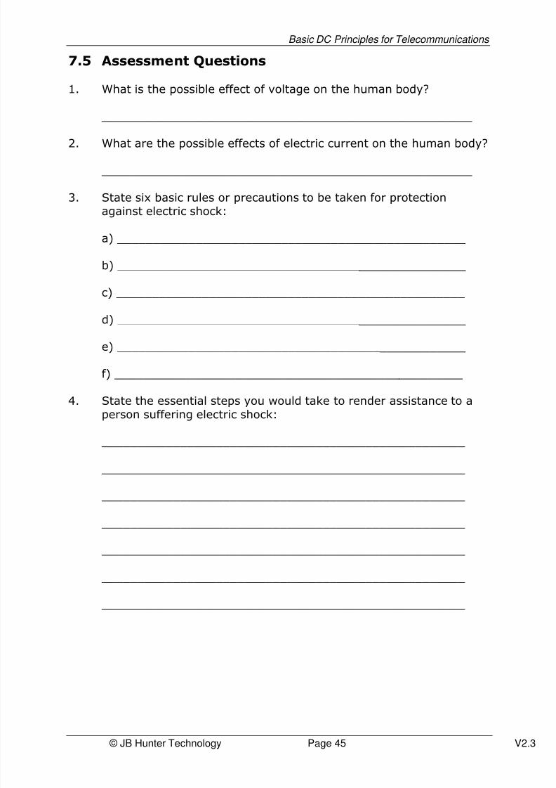
7.5 Assessment Questions
1. What is the possible effect of voltage on the human body?
____________________________________________________
2. What are the possible effects of electric current on the human body?
____________________________________________________
3. State six basic rules or precautions to be taken for protectionagainst electric shock:
a) _________________________________________________
b) _________________________________________________
c) _________________________________________________
d) _________________________________________________
e) _________________________________________________
f) _________________________________________________
4. State the essential steps you would take to render assistance to a
person suffering electric shock:
___________________________________________________
___________________________________________________
___________________________________________________
___________________________________________________
___________________________________________________
___________________________________________________
___________________________________________________
8/3/2019 Basic DC Principles for Telecommunications Tutorial
http://slidepdf.com/reader/full/basic-dc-principles-for-telecommunications-tutorial 46/65
Basic DC Principles for Telecommunications
© JB Hunter Technology Page 46 V2.3
Chapter 8 – Electrical Measuring Instruments
8.1 Electrical Instruments
Electrical instruments are available to measure:
a) voltage both dc and acb) current both dc and acc) resistance
Some electrical measuring instruments specialise in measurement of oneof these electric quantities only:
a) a voltmeter measures voltage onlyb) an ammeter measures current onlyc)
an ohm meter measures resistance only
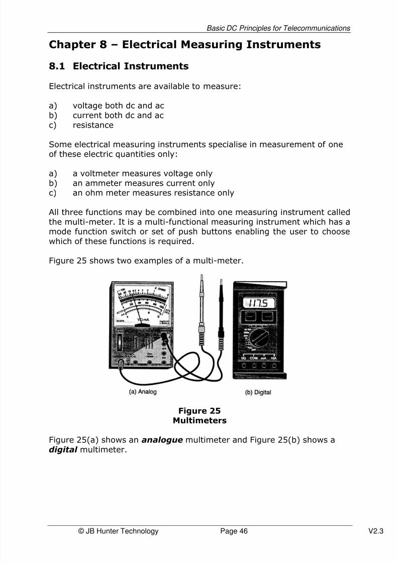
All three functions may be combined into one measuring instrument calledthe multi-meter. It is a multi-functional measuring instrument which has amode function switch or set of push buttons enabling the user to choosewhich of these functions is required.
Figure 25 shows two examples of a multi-meter.
Figure 25Multimeters
Figure 25(a) shows an analogue multimeter and Figure 25(b) shows adigital multimeter.

8/3/2019 Basic DC Principles for Telecommunications Tutorial
http://slidepdf.com/reader/full/basic-dc-principles-for-telecommunications-tutorial 47/65
Basic DC Principles for Telecommunications
© JB Hunter Technology Page 47 V2.3
The disadvantages of the analogue version are:
a) More easily damaged due to mechanical shock as the deflectingneedle mechanism is sensitive to mechanical shock.
b) If the leads are incorrectly connected to the point of measurementon the electric circuit then the deflecting needle moves backwards
and may be damaged.c) If the incorrect range is selected for the measurement concerned
the deflecting mechanism may be overloaded and the deflectingneedle damaged.
As the digital multimeter does not suffer from these disadvantages it hasbecome the more popular instrument.
8.2 Multi-Meter Controls
Before connecting a multimeter to the points of circuit measurement, thecorrect functions/control choices must be made and the connecting leadsinserted into the correct positions on the instrument.
Figure 26 refers.
Figure 26Digital Multimeter

8/3/2019 Basic DC Principles for Telecommunications Tutorial
http://slidepdf.com/reader/full/basic-dc-principles-for-telecommunications-tutorial 48/65
Basic DC Principles for Telecommunications
© JB Hunter Technology Page 48 V2.3
These aspects must be selected carefully:
a) Which function is required: voltage, current or resistance?b) If voltage, dc or ac must be selected.c) The best range must be selected. For example, if selecting voltage
there may be a choice of the following ranges: 3v, 10v, 30v, 100v,
300v, 1000v on a typical multi-meter. It is good practice to select ameasuring range higher than the value expected to be measured toprevent overload.
d) Select the right terminals on the instrument to which themeasuring leads (probes) are to be connected. There may be a “common” terminal for both dc volts and dc current and ohmmeasurement. The other lead will go in the appropriate terminal fordc volts, dc current or ohms. Connecting leads are often colourcoded in black (negative) and red (positive). The black lead goes tothe common terminal. In the case of ac current, select the terminals
appropriately labelled. In ac measurement, the red and black colourcoding do not have the same significance as for dc measurements.
8.3 Circuit Connections
In the case of dc measurements it is vital to connect the positive (red)lead to the point in the circuit which is at the higher voltage and thenegative (black) lead to the point of lower voltage. If this is not done, themeter will deflect backwards (if analogue) or will show a negative sign onthe display (if digital).
In ac measurements, this colour coding “polarity” is not significant.
8.4 Interpreting Measurements
It is easy to misread a multimeter.
The display has meaning only if you are sure which function it is on andwhich range has been selected.

8/3/2019 Basic DC Principles for Telecommunications Tutorial
http://slidepdf.com/reader/full/basic-dc-principles-for-telecommunications-tutorial 49/65
Basic DC Principles for Telecommunications
© JB Hunter Technology Page 49 V2.3
8.5 Insulation Resistance Tester “Megger”
Apart from the multimeter, another instrument which is of particular useto those in the cabling industry is the insulation resistance tester,commonly known as the “megger” because it measures megohms.
This instrument is a resistance tester and measures ohms but is designedparticularly to measure very high resistances such as that of the insulationof a wire or cable. Very high resistances are in the megohm region(millions of ohms).
Such instruments use a higher voltage source for the measurement thanthe multimeter.
Typically a 500v or 1000v option for testing is provided on the functionswitch/button of the “megger”.
The instrument can only deliver very low currents and is not, with correctuse, of danger to the human body however, you are well advised not totouch the terminals or bare connecting points of a megger when using theinstrument.
However, cable pairs and some electronic equipment have capacitancewhich charges up to the voltage of test such as 500v or 1000v. It isimportant to discharge the cable pair or equipment using a conductorbefore touching exposed terminals or wires which may have been charged
up during the “megger” test. The capacitance of cable pairs andequipment can hold enough electronic charge at higher voltages to givethe human body a nasty shock if discharged through the body.
In the telephone and data cabling industry, the ‘megger’ provides a veryuseful test for the insulation integrity of:
• wires and cables• electrical apparatus• cable joints.
8/3/2019 Basic DC Principles for Telecommunications Tutorial
http://slidepdf.com/reader/full/basic-dc-principles-for-telecommunications-tutorial 50/65
Basic DC Principles for Telecommunications
© JB Hunter Technology Page 50 V2.3
8.6 Assessment Questions
1. State the three functions of a multimeter:
a) ___________________________
b) ___________________________
c) ___________________________
2. State the purpose of the “function” switch or push buttons on amultimeter:
____________________________________________________
3. State the purpose of “range” selection on a multimeter:
____________________________________________________
4. What is the best range to select before making an electricalmeasurement?
____________________________________________________
5. How do you determine to which terminals you connect the
instrument test leads?
____________________________________________________
____________________________________________________
6. What is the purpose of a “megger”?
____________________________________________________
7. State any precautions to be observed when using a “megger”?
____________________________________________________
____________________________________________________

8/3/2019 Basic DC Principles for Telecommunications Tutorial
http://slidepdf.com/reader/full/basic-dc-principles-for-telecommunications-tutorial 51/65
Basic DC Principles for Telecommunications
© JB Hunter Technology Page 51 V2.3
Chapter 9 – Magnetism and Electro-Magnetism
9.1 Magnetism and Permanent Magnets
Figure 27Like Magnet Poles Repel
A permanent magnet has a north and a south pole.
If you place two permanent magnets close together and in line with eachother, they will be attracted together in one orientation and repel eachother in the opposite orientation. When the north poles are close togetherthey repel and when the north pole of one is close to the south pole of theother, they will be attracted.
Like poles repel and unlike poles attract is the “rule”.
This force of attraction or repulsion is due to magnetism, a force
developed due to the combined effects of small atomic level particles of matter when their individual magnetic “domains” are aligned. Thisalignment can be done by an external magnetic force.
A material which retains the magnetic property when the externalmagnetic force is removed is called a permanent magnet.
The magnetising force is called “magneto-motive force”.
It is analogous to the “electromotive force (EMF) in electrical terminology.
There are very few materials which respond to electro-motive force andcan be “magnetised”. There is an even smaller number of materials whichretain their magnetism after the magneto-motive force is removedthereby becoming permanent magnets.

8/3/2019 Basic DC Principles for Telecommunications Tutorial
http://slidepdf.com/reader/full/basic-dc-principles-for-telecommunications-tutorial 52/65

8/3/2019 Basic DC Principles for Telecommunications Tutorial
http://slidepdf.com/reader/full/basic-dc-principles-for-telecommunications-tutorial 53/65
Basic DC Principles for Telecommunications
© JB Hunter Technology Page 53 V2.3
Figure 29The Magnetic Field Created when a Current is
Passed Through a Multi-Turn Solenoid
When an electric current flows through a coil of wire a magnetic force fieldis created. The more turns of wire in the coil combined with more electriccurrent in the coil, the stronger the resulting magnetic field.
If the current is dc, the magnetic field will have a “permanent” north and
south poles whilst the current continues to flow.
It has the same external effect as a permanent magnet.However, should the current be turned off, the magnetic field collapsesand the magnetic force disappears.
This effect is called electro-magnetism.
This effect is used in some telephone receivers and is used in audioequipment loudspeakers.
Consider however, what would happen if the current flowing through thecoil was ac.
This means that the current would be alternately flowing in one directionthen the opposite direction. This would produce a correspondingalternating magnetic force with the north and south poles alternating ateach end in sequence with the alternating current and at the same “frequency”.
“Frequency” is how many times per second the magnetic field does a
complete reversal cycle, “N-S-N”.
8/3/2019 Basic DC Principles for Telecommunications Tutorial
http://slidepdf.com/reader/full/basic-dc-principles-for-telecommunications-tutorial 54/65
Basic DC Principles for Telecommunications
© JB Hunter Technology Page 54 V2.3
9.3 Loudspeaker Construction
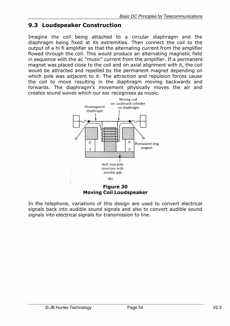
Imagine the coil being attached to a circular diaphragm and thediaphragm being fixed at its extremities. Then connect the coil to theoutput of a hi fi amplifier so that the alternating current from the amplifierflowed through the coil. This would produce an alternating magnetic fieldin sequence with the ac “music” current from the amplifier. If a permanentmagnet was placed close to the coil and on axial alignment with it, the coilwould be attracted and repelled by the permanent magnet depending onwhich pole was adjacent to it. The attraction and repulsion forces causethe coil to move resulting in the diaphragm moving backwards andforwards. The diaphragm’s movement physically moves the air andcreates sound waves which our ear recognises as music.
Figure 30Moving Coil Loudspeaker
In the telephone, variations of this design are used to convert electricalsignals back into audible sound signals and also to convert audible soundsignals into electrical signals for transmission to line.

8/3/2019 Basic DC Principles for Telecommunications Tutorial
http://slidepdf.com/reader/full/basic-dc-principles-for-telecommunications-tutorial 55/65
Basic DC Principles for Telecommunications
© JB Hunter Technology Page 55 V2.3
9.4 Assessment Questions
1. Sate two materials which can be magnetised.
a) _______________________________
b) _______________________________
2. State two metals which cannot be magnetised.
a) __________________________________
b) __________________________________
3. Complete these sentences which describe the forces operatingbetween the poles of magnets:
Like poles ___________ Unlike poles ___________
4. Apart from the permanent magnet, describe another source of magneto-motive force. ______________________________________________________
______________________________________________________
5. If alternating current (ac) is passed through a coil, what effect does
this have on the poles of the electro magnet so formed?
______________________________________________________
______________________________________________________
8/3/2019 Basic DC Principles for Telecommunications Tutorial
http://slidepdf.com/reader/full/basic-dc-principles-for-telecommunications-tutorial 56/65
Basic DC Principles for Telecommunications
© JB Hunter Technology Page 56 V2.3
Chapter 10 – Answers to End of Chapter
Assessment Questions
Answers to Evaluation Exercises of 1.7
1. a)2. b)3. Copper, aluminium, silver or others mentioned in the text4. Mica, plastic, porcelain or others mentioned in the text5. Germanium, silicon6. Electro-motive force7. Electrical pressure8. Car battery, solar cells, turbine-driven electrical generator or car
(electrical generator)9. An electrical current is the combined effect of many electrons
flowing along a conductor10. Electric radiator, electric toaster, electric light globe
Answers to Evaluation Exercises of 2.6
1. Volt, v2. a) High voltage is above 1500v
b) Extra low voltage is below 60vc) Low voltage is below 1500v but above 60v
3. Extra low voltage
4. Low voltage5. Amp, Ω 6. Silver7. Nichrome8. a) Its length
b) Its materialc) Its diameter (cross-sectional area)d) Its temperature
9. a)10. a)
11. a)

8/3/2019 Basic DC Principles for Telecommunications Tutorial
http://slidepdf.com/reader/full/basic-dc-principles-for-telecommunications-tutorial 57/65
Basic DC Principles for Telecommunications
© JB Hunter Technology Page 57 V2.3
Answers to Assessment Questions 3.4
1. Direct current2. Alternating current3. DC
4. AC5. AC6. 52 volts and it produces dc
Answers to Assessment Questions 4.7
1. a) Car batteryb) Solar cellsc) Turbine driven electrical generator
2.
3.
4. a) For indoor … PVCb) For outdoor… polyethylene
5.
6. a) ohmb) Ω
7. one thousand8. 10 million ohms9.
10.
11.
Insulated Conductors TwistedTogether to Form Pairs
Overall
Protective Jacket
Individual BareConductors

8/3/2019 Basic DC Principles for Telecommunications Tutorial
http://slidepdf.com/reader/full/basic-dc-principles-for-telecommunications-tutorial 58/65
Basic DC Principles for Telecommunications
© JB Hunter Technology Page 58 V2.3
12. a) Block dcb) Pass ac
13.
14.
Answers to Assessment Questions 5.7
1.
2. I = V ÷ R = 9 ÷ 18 Amps = 0.5 A = 500 mA3. Increase4. Decrease5. Ohms Law R= V ÷ I6. Lower than the lowest resistor value7. 100. See below for wworkings.
Total Resistance of parallel circuit where R1= 200 and R2= 200.
RT = ____1_____1 + 1R1 R2
RT = 1 _1_ + _1_200 200
= ______1 ______
0.005 + 0.005
= __1__0.01
Therefore: RT = 100
9v18 Ω

8/3/2019 Basic DC Principles for Telecommunications Tutorial
http://slidepdf.com/reader/full/basic-dc-principles-for-telecommunications-tutorial 59/65
Basic DC Principles for Telecommunications
© JB Hunter Technology Page 59 V2.3
Answers to Assessment Questions 6.4
1. mA means milliamps2. 0.03 Amps = 30 mA3. 0.005 A = 5 mA
4. 1000Ω
5. I = 52 ÷ 1000 = 0.052 A = 52 mA
Answers to Assessment Questions 7.5
1. May break down skin resistance and allow electric current into thebody
2. Depending on the level of current will result in a tingling sensationat low current levels and may cause heart and breathing stoppageand death at higher currents
3. a) Don’t work with wet hands or on a wet floorb) Use insulating clothing with no metallic members and rubbersoled shoes and rubber glovesc) Never work under the influence of alcohol or drugs or when tiredand not alertd) Don’t wear conductive jewellery or metallic rings/watchese) Where ever possible switch off the power and unplug and whereappropriate discharge, electrical apparatus before working on it.f) Consider the conductive (metallic) parts of any electric appliance,circuit, terminals, conductors, wires and equipment as being
hazardous until proved otherwise4. a) Act promptly but don’t put yourself at riskb) If possible, quickly switch off the power source or pull out thepower cord from its socket to make the area safec) If you cannot remove the power, remove the person from contactwith power by using insulating material in a safe method which doesnot put yourself in contact with the person or powerd) Apply CPR if trained call for emergency assistance and get aperson trained in CPR if you aren’t, ASAP.
8/3/2019 Basic DC Principles for Telecommunications Tutorial
http://slidepdf.com/reader/full/basic-dc-principles-for-telecommunications-tutorial 60/65

8/3/2019 Basic DC Principles for Telecommunications Tutorial
http://slidepdf.com/reader/full/basic-dc-principles-for-telecommunications-tutorial 61/65
Basic DC Principles for Telecommunications
© JB Hunter Technology Page 61 V2.3
Appendix A – Resistor Colour Codes
Basic Resistor Colour Code
It is often impractical to write the value of a resistor on the outside of its
case. Therefore coloured bands around the case of the resistor are oftenused to indicate the appropriate value of resistance. These bands are easyto read and can be seen from virtually any angle.
Each colour represents a particular number. The basic colour codes are:
Black band 0Brown band 1Red band 2Orange band 3Yellow band 4Green band 5Blue band 6Violet band 7Grey band 8White band 9
The first two coloured bands will give the first figures in the resistancevalue. For example:
Red band – violet band gives 27
Green band – blue band gives 56
The third coloured band will give the number of zeros to be counted afterthe second colour. It must be noted that gold and silver are sometimesused as the third colour. Gold multiplies the first two numbers by 0.1 andsilver by 0.01 for example:
Red band – violet band – brown band = 270ohmsGreen band – blue band – yellow band = 560,000ohmsBrown band – grey band – gold band =1.8ohms
8/3/2019 Basic DC Principles for Telecommunications Tutorial
http://slidepdf.com/reader/full/basic-dc-principles-for-telecommunications-tutorial 62/65
Basic DC Principles for Telecommunications
© JB Hunter Technology Page 62 V2.3
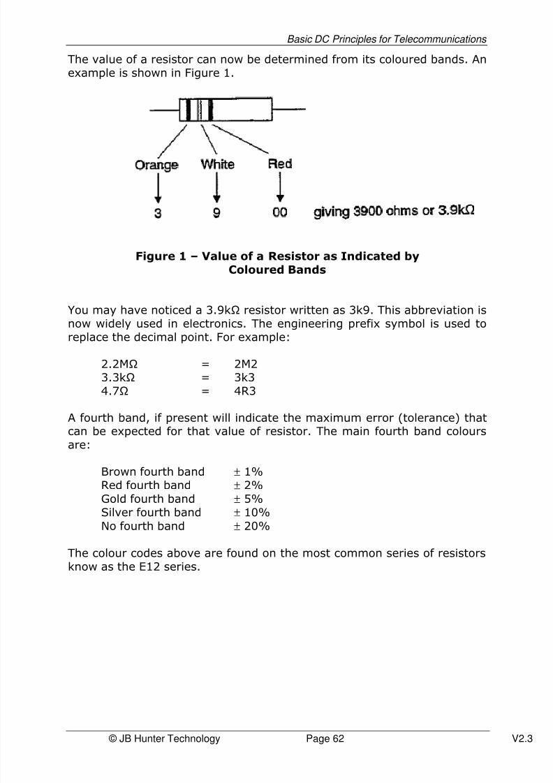
The value of a resistor can now be determined from its coloured bands. Anexample is shown in Figure 1.
Figure 1 – Value of a Resistor as Indicated by
Coloured Bands
You may have noticed a 3.9kΩ resistor written as 3k9. This abbreviation isnow widely used in electronics. The engineering prefix symbol is used toreplace the decimal point. For example:
2.2MΩ = 2M23.3kΩ = 3k34.7Ω = 4R3
A fourth band, if present will indicate the maximum error (tolerance) thatcan be expected for that value of resistor. The main fourth band coloursare:
Brown fourth band ± 1%Red fourth band ± 2%
Gold fourth band ± 5%Silver fourth band ± 10%
No fourth band ± 20%
The colour codes above are found on the most common series of resistorsknow as the E12 series.

8/3/2019 Basic DC Principles for Telecommunications Tutorial
http://slidepdf.com/reader/full/basic-dc-principles-for-telecommunications-tutorial 63/65
Basic DC Principles for Telecommunications
© JB Hunter Technology Page 63 V2.3
Using the basic resistor colour code above, determine the values of resistance and tolerance for the resistors below.
Exercise A – Resistor Colour Codes
3.11......................... 3.12...................... 3.13.......................
3.14........................ 3.15........................ 3.16.......................
3.17......................... 3.18....................... 3.19......................

8/3/2019 Basic DC Principles for Telecommunications Tutorial
http://slidepdf.com/reader/full/basic-dc-principles-for-telecommunications-tutorial 64/65
Basic DC Principles for Telecommunications
© JB Hunter Technology Page 64 V2.3
Philips Film Resistors
Note: Philips offer a range of high precision film resistors with tolerancesas low as 0.1%. In these cases the third coloured band gives a third valueand a fourth band gives the multiplier or number of zeroes. A fifth bandgives the tolerance. A sixth band, in precision metal film resistors, will
give the temperature coefficient. For example a Philips resistor has thecolour coding:
brown red yellow brown brown
Value: 1 2 4 0 1%
OR 1240 ± 1% ≡ 1.24KΩ ± 1%

8/3/2019 Basic DC Principles for Telecommunications Tutorial
http://slidepdf.com/reader/full/basic-dc-principles-for-telecommunications-tutorial 65/65
Basic DC Principles for Telecommunications
Answers for Exercise A - Resistor Colour Codes
3.11......2200 @ 5%.
3.12......560 @ 20%.
3.13......47 @ 10%.
3.14......1.5M @ 10%.
3.15......2.7 @ 5%.
3.16......33K @ 20%.
3.17......100 @ 1%.
3.18......100K @ 5%.
3.19......12K @ 2%.
JB Hunter TechnologyPO Box 2339
DANGAR NSW 2309Phone 1800 672 933