basic humidification 101 - arpis.com
TRANSCRIPT
BasicHumidification
101
What is Humidity? . . . . . . . . . . . . . . . . . . . . . . . . . . . . . . . . 2
Why is Dry Air a Problem? . . . . . . . . . . . . . . . . . 2-3
Why Humidify? . . . . . . . . . . . . . . . . . . . . . . . . . . . . . . . . . . . 3-5
Humidification Sizing . . . . . . . . . . . . . . . . . . . . . . . . . 5-9
Humidification Technologies . . . . . . . . . . . . . 9-12
Humidification Selection . . . . . . . . . . . . . . . . . . . . . 13
Humidifier Installation . . . . . . . . . . . . . . . . . . . . . 13-16
Humidifier Maintenance . . . . . . . . . . . . . . . . . . . 17-19
Humidification Certification Test . . . . . 20-24
What is Humidity?™
Why is Dry Air a Problem?™
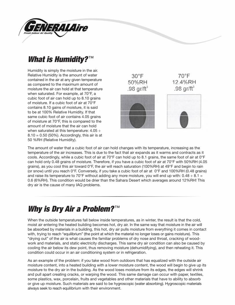
Humidity is simply the moisture in the air. Relative Humidity is the amount of water contained in the air at any given temperature as compared to the maximum amount of moisture the air can hold at that temperature when saturated. For example, at 70°F, a cubic foot of air can hold up to 8.10 grains of moisture. If a cubic foot of air at 70°F contains 8.10 gains of moisture, it is said to be at 100% Relative Humidity. If that same cubic foot of air contains 4.05 grains of moisture at 70°F, this is compared to the amount of moisture that the air can hold when saturated at this temperature: 4.05 ÷ 8.10 = 0.50 (50%). Accordingly, this air is at 50 %RH (Relative Humidity).
The amount of water that a cubic foot of air can hold changes with its temperature, increasing as the temperature of the air increases. This is due to the fact that air expands as it warms and contracts as it cools. Accordingly, while a cubic foot of air at 70°F can hold up to 8.1 grains, the same foot of air at 0°F can hold only 0.48 grains of moisture. Therefore, if you have a cubic foot of air at 70°F with 50%RH (4.05 grains), as you cool this air toward 0°F, the air will reach saturation (100%RH) at 49°F and begin to rain (or snow) until you reach 0°F. Conversely, if you take a cubic foot of air at 0°F and 100%RH (0.48 grains) and raise its temperature to 70°F without adding any more moisture, you will end up with: 0.48 ÷ 8.1 = 0.6 (6%RH). This condition would be drier than the Sahara Desert which averages around 12%RH! This dry air is the cause of many IAQ problems.
When the outside temperatures fall below inside temperatures, as in winter, the result is that the cold, moist air entering the heated building becomes hot, dry air. In the same way that moisture in the air will be absorbed by materials in a building, this hot, dry air pulls moisture from everything it comes in contact with, trying to reach “equilibrium” (the point at which the material no longer loses or gains moisture). This “drying out” of the air is what causes the familiar problems of dry nose and throat, cracking of wood-work and materials, and static electricity discharges. This same dry air condition can also be caused by cooling the air below its dew point, thus removing moisture (dehumidifying), and then reheating it. This condition could occur in an air conditioning system or in refrigeration.
As an example of the problem: if you take wood from outdoors that has equalized with the outside air moisture content, into a heated building with a lower moisture content, the wood will begin to give up its moisture to the dry air in the building. As the wood loses moisture from its edges, the edges will shrink and pull apart creating cracks, or warping the wood. This same damage can occur with paper, textiles, some plastics, wax, porcelain, fruits and vegetables and other materials that have to ability to absorb or give up moisture. Such materials are said to be hygroscopic (water absorbing). Hygroscopic materials always seek to reach equilibrium with their environment.
In the case of a museum, where expensive paintings, sculptures and other hygroscopic materials are kept, rapid changes in Relative Humidity can be devastating and will eventually destroy the artifacts. In a printing operation, paper that is rapidly drying while running through a press, will shrink and curl causing jamming, tearing and even misregistration of printing colors. In a microchip wafer fabrication laboratory, slight changes in the dimension of a Silicon wafer can result in chips that are not usable.
The key to protection of hygroscopic materials is stability of the environ-ment. It is detrimental to permit the Relative Humidity to vary rapidly or widely throughout the year. This is
one of the reasons why control (or stabilization) of the Relative Humidity is becoming an important part of Indoor Air Quality. This is accomplished by dehumidifying when the air becomes too moist and humidifying when the air becomes too dry.
Why Humidify?™
There are 3 basic reasons why a home should be humidified:
1. Static Electricity is occurring in the home. 2. Health and comfort issues caused by dry air. 3. Protection of hygroscopic materials in the home.
1. Static Electricity
Static electricity is drastically reduces when the relative humidity is maintained above 35%™. The average static discharge is 5,000 volts. There are many things in the home that can be affected by static electricity. Besides the discomfort caused by a static discharge to another individual or house-hold material, it can be destructive to electronics, computer storage devices, compact discs,….
For example, a computer microchip only needs 10 volts of static discharge to be destroyed. You can destroy files stored on compact discs if a static discharge is made through the disc, an irreplaceable loss. Other minor difficulties related to static would include paper jams in printers and copiers, unman-ageable hair, along with dust attraction to computer and TV screens.
The answer to these issues is to hu-midify the home to levels above 35% RH. Why take the chance of destroy-ing an electronic device or losing digi-tal photos of the family vacation.
2. Health and Comfort Issues
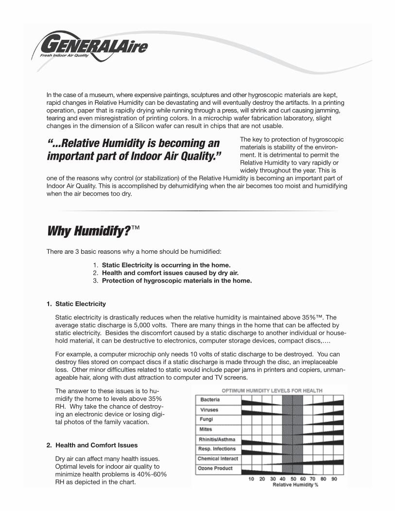
Dry air can affect many health issues. Optimal levels for indoor air quality to minimize health problems is 40%-60% RH as depicted in the chart.
“...Relative Humidity is becoming an important part of Indoor Air Quality.”
The chart simply shows that Bacteria, Viruses, Rhinitis/Asthma, Resp. Infections, and Ozone Product are greatly reduced at levels above 40% RH and below 60% RH. If the home RH falls below 40% an environment has been created that increases the presence of unhealthy agents. Other health related results of dry air include nasal congestion, nose bleeds, dry itchy skin, chapped lips, and even brittle finger nails.
Human discomfort in dry homes results in moisture being evaporated on the sur-face of the skin resulting in the human body feeling cold even though the room temperature is 72 degrees. Humidifica-tion will reduce surface evaporation and allow the body to feel warmer at lower temperature settings. Therefore one can
increase RH and lower the temperature in the home resulting in heat energy savings. Other discomfort can be caused by outgases from hygroscopic materials in the home resulting in unwanted chemicals and odors. Maintaining proper RH levels to avoid the absorption of the moisture containing contami-nants in building materials avoids those irritants being distributed in the air and coming in contact, both external and internal, with the human body. Another easily recognizable discomfort from dry air af-fects those individuals that wear contact lenses. Contact lenses are hygroscopic and need moisture to maintain their shape. Dry conditions will cause contact lenses to curl resulting in discomfort and the use of additional eye drops to keep the lenses hydrated. It is also implied that health conditions created by dry environments will directly affect the body and cause discomfort as well.
Maintain RH levels of 40%-60% and keep those unhealthy conditions from increasing and increase your level of comfort in the home.
3. Protection of Household Goods
What is it that a homeowner might want to protect? It relates back to hygroscopic materials discussed earlier in this training manual. Hygroscopic materials will give off and absorb moisture and during this process will change shape. Examples of hygroscopic materials in a home include wood flooring, molding, musical instruments, kitchen cabinets, carpet fiber, and canvas used for artwork. If low levels of RH are consistent in the home these hygroscopic materials will give off the moisture they contain and cause the material to change shape, become brittle, splinter, and crack. This process can destroy those very materials that homeowners have spent thousands of dollars on.
Wood flooring is one of the most common materials to be easily observed by the affects of dry air. The wood floor joints will separate and the wood will crack. Resulting in possible splintering and uneven floors. Wood molding will also show visible signs of shrinking along the wall it is fastened to. Gapping will occur and separating of molding joints will become noticeable. Molding separation creates additional cost in caulking and painting to conceal damage caused by dry air. Musical instruments made of wood rely on the consistent shape of the wood to stay in tune. When dry air causes the wood to shrink the piano wires will no longer have the same tension creating a different sound. The same is true for guitars and other string instruments. Therefore one must take the time and money to tune the instrument.
“Other health related results of dry air include nasal congestion, nose bleeds, dry itchy skin, chapped lips, and even brittle finger nails.”
“Examples of hygroscopic materials in a home include wood flooring, molding, musical instruments, kitchen cabinets, carpet fiber, and canvas used for artwork.”
Humidification SizingFirst, let’s look at why you would need to determine the load for humidification. Just like a heat load cal-culation where you determine how many Btu’s are needed to properly heat a house during winter condi-tions, one needs to determine how much moisture to add. For example, we do not size a furnace based on total square footage. One must consider outside design conditions, insulation, windows…to prop-erly select a heating system. If it is required to run heat load calculations and cooling load calculation we should be able to verify humidification needs as well. Current humidifier charts are making general assumptions using home square footage and claiming specific humidifiers will handle the requirement. These general charts do not consider all factors that play roles in calculating the humidification load. Since there are formulas to calculate humidification loads we should make every effort to take the time to use them. Just like the industry abandoned a/c sizing generalizations now we need to apply the same logic and process to humidification loads.
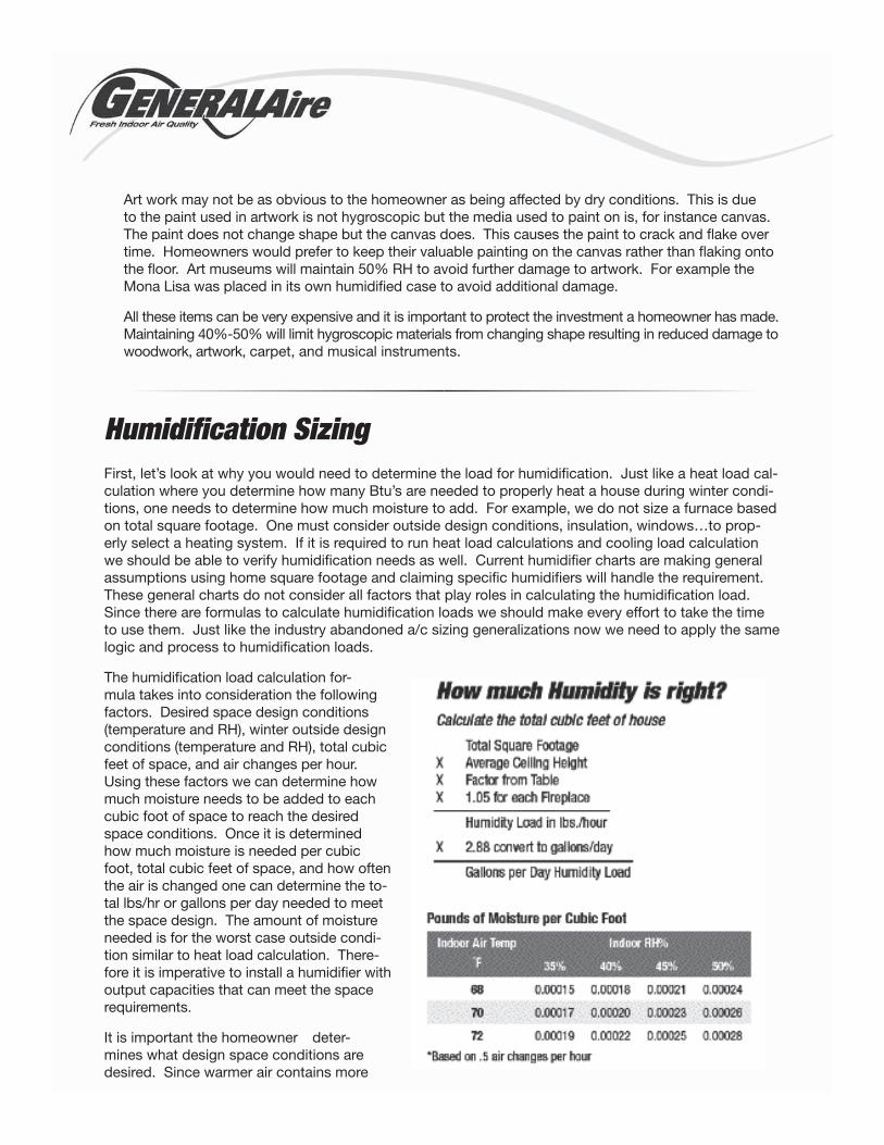
The humidification load calculation for-mula takes into consideration the following factors. Desired space design conditions (temperature and RH), winter outside design conditions (temperature and RH), total cubic feet of space, and air changes per hour. Using these factors we can determine how much moisture needs to be added to each cubic foot of space to reach the desired space conditions. Once it is determined how much moisture is needed per cubic foot, total cubic feet of space, and how often the air is changed one can determine the to-tal lbs/hr or gallons per day needed to meet the space design. The amount of moisture needed is for the worst case outside condi-tion similar to heat load calculation. There-fore it is imperative to install a humidifier with output capacities that can meet the space requirements.
It is important the homeowner deter-mines what design space conditions are desired. Since warmer air contains more
Art work may not be as obvious to the homeowner as being affected by dry conditions. This is due to the paint used in artwork is not hygroscopic but the media used to paint on is, for instance canvas. The paint does not change shape but the canvas does. This causes the paint to crack and flake over time. Homeowners would prefer to keep their valuable painting on the canvas rather than flaking onto the floor. Art museums will maintain 50% RH to avoid further damage to artwork. For example the Mona Lisa was placed in its own humidified case to avoid additional damage.
All these items can be very expensive and it is important to protect the investment a homeowner has made. Maintaining 40%-50% will limit hygroscopic materials from changing shape resulting in reduced damage to woodwork, artwork, carpet, and musical instruments.
The manual calculation chart uses .5 air changes per hour and this must be entered in the web version. Web version also enables you to adjust the air changes. Most new homes are constructed to have .35 air changes therefore .5 provides adequate air changes and works well with looser older homes. It is better to overestimate air changes and have too much capacity than to underestimate and not meet the space demand. You should also consider additional requirements for open flue fireplaces (5% per fire-place) and for very old homes with single pane windows increasing the calculated load by 25%.
Once the humidification load requirement is calculated, a humidifier must be selected with output capac-ity that exceeds the homes requirement. If a selected humidifier does not have the output required to meet the space demands the desired RH will not be met and homeowners will have purchased a product that can not meet their space requirements. Very similar to installing 3 ton AC unit when design condi-tions require 5 tons. The homeowner will not be able to maintain a comfortable temperature because there are not enough btus to satisfy the cooling load requirement.
moisture both temp and RH level are needed. There is a 2% RH change for every 1 degree tempera-ture change. Also homeowners must determine what their goal of humidification in their home. Factors include materials like wood flooring, kitchen cabinets, carpet, artwork canvas, pianos……are considered hygroscopic, materials that absorb/emit moisture and will change dimensions during the process. It is this dimensional change that is damaging to these materials. Most all museums and art galleries will maintain 45-55% RH for the protection of the contents. There are also health benefits to avoiding low RH levels that include dry skin, bloody noses, respiratory issues, sinus congestion…… Target RH levels for healthy environments would be between 40-60% as outlined in the chart below. Lastly one can elimi-nate static electricity at levels above 35% RH. Taking all of these things into consideration a residence should use a target RH of 40-50% in the home.
There are some industry tools available to use that make this process simple and easy. The load calculation can be performed manually with some simple math by using the formula and RH chart provided by General-Aire in the Elite Steam brochure (shown to the right).
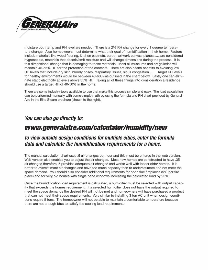
You can also go directly to:
www.generalaire.com/calculator/humidity/new
to view outside design conditions for multiple cities, enter the formula data and calculate the humidification requirements for a home.
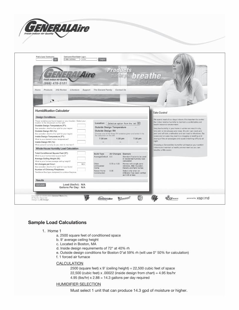
Sample Load Calculations
1. Home 1 a. 2500 square feet of conditioned space b. 9’ average ceiling height c. Located in Boston, MA d. Inside design requirements of 72° at 40% rh e. Outside design conditions for Boston 0°at 59% rh (will use 0° 50% for calculation) f. 1 forced air furnace
CALCULATION 2500 (square feet) x 9’ (ceiling height) = 22,500 cubic feet of space 22,500 (cubic feet) x .00022 (inside design from chart) = 4.95 lbs/hr 4.95 (lbs/hr) x 2.88 = 14.3 gallons per day required
HUMIDIFIER SELECTION
Must select 1 unit that can produce 14.3 gpd of moisture or higher.
Sample Load Calculations (continued)
2. Home 2 a. 4500 square feet of conditioned space b. 8’ average ceiling height c. Located in Aspen, CO d. Inside design requirements of 70° at 45% rh e. Outside design conditions for Aspen area -15°at 64% rh (will use 0° 50% for calculation) f. 2 forced air furnaces
CALCULATION 4500 (square feet) x 8’ (ceiling height) = 36,000 cubic feet of space 36,000 (cubic feet) x .00023 (inside design from chart) = 8.28 lbs/hr 8.28 (lbs/hr) x 2.88 = 23.8 gallons per day required 23.8 x 10% (2 wood fireplaces) = 2.38 gpd additional load 23.8 + 2.38 = 26.2 gallons per day required
HUMIDIFIER SELECTION
Must select 1 or 2 units that can produce 26.2 gpd of moisture or higher.
3. Home 3 a. 9500 square feet of conditioned space b. 10’ average ceiling height c. Historic home with single pane windows d. Inside design requirements of 72° at 35% rh e. Outside design conditions for Richmond -15°at 60% rh (will use 0° 50% for calculation) f. 4 forced air furnaces
CALCULATION 9500 (square feet) x 10’ (ceiling height) = 95,000 cubic feet of space 95,000 (cubic feet) x .00019 (inside design from chart) = 18.1 lbs/hr 18.1 (lbs/hr) x 2.88 = 52 gallons per day required 52 x 25% (Old home) = 13 gpd additional load 52 + 13 = 65 gallons per day required
HUMIDIFIER SELECTION
Must select 1, 2, 3, or 4 units that can produce 65 gpd of moisture or higher.
4. Home 4 a. 7000 square feet of conditioned space b. 9’ average ceiling height c. 3 wood burning fireplaces d. Located in New Haven, CT e. Inside design requirements of 72° at 50% rh f. Outside design conditions for New Haven 0°at 65% rh (will use 0° 50% for calculation) g. 3 forced air furnace
CALCULATION 7000 (square feet) x 9’ (ceiling height) = 63,000 cubic feet of space 63,000 (cubic feet) x .00028 (inside design from chart) = 17.6 lbs/hr 17.6 (lbs/hr) x 2.88 = 50.8 gallons per day 50.8 x 15% (3 wood fireplaces) = 7.62 gpd additional load 50.8 + 7.62 = 58.4 gallons per day required
HUMIDIFIER SELECTION
Must select 1, 2, or 3 units that can produce 58.4 gpd of moisture or higher.
Remember it is better to have too much humidification output than to not have enough. The humidifier will operate only for the time needed to satisfy the humidistat similar to how long a furnace will run to satisfy temperature. Outside conditions affecting inside design conditions dictates the operating time and cycles. ALWAYS perform a load calculation to avoid under sizing equipment resulting in poor performance and unsatisfied homeowners.
Humidification TechnologiesThere are many ways to add humidity to a space but there are 2 primary systems are installed in resi-dential applications. Within each system there are multiple techniques used and each will be outlined as they pertain to whole house humidification. The first is Evaporative Pad type systems and the second is Electric Steam systems. Each system has advantages and disadvantages that will be reviewed so the installing contractor can apply the appropriate technology to the residence being humidified.
Evaporative Pad systems
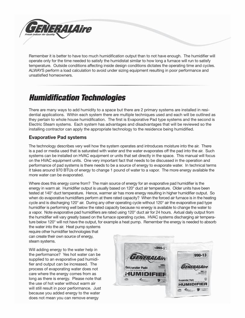
The technology describes very well how the system operates and introduces moisture into the air. There is a pad or media used that is saturated with water and the water evaporates off the pad into the air. Such systems can be installed on HVAC equipment or units that set directly in the space. This manual will focus on the HVAC equipment units. One very important fact that needs to be discussed in the operation and performance of pad systems is there needs to be a source of energy to evaporate water. In technical terms it takes around 970 BTUs of energy to change 1 pound of water to a vapor. The more energy available the more water can be evaporated.
Where does this energy come from? The main source of energy for an evaporative pad humidifier is the energy in warm air. Humidifier output is usually based on 120° duct air temperature. Older units have been tested at 140° duct temperature. Hence, warmer air has more energy resulting in higher humidifier output. So when do evaporative humidifiers perform at there rated capacity? When the forced air furnace is in the heating cycle and is discharging 120° air. During any other operating cycle without 120° air the evaporative pad type humidifier is performing well below the rated capacity because no energy is available to change the water to a vapor. Note evaporative pad humidifiers are rated using 120° duct air for 24 hours. Axtual daily output from the humidifier will vary greatly based on the furnace operating cycles. HVAC systems discharging air tempera-ture below 120° will not have the output, for example a heat pump. Remember the energy is needed to absorb the water into the air. Heat pump systems require other humidifier technologies that can create their own source of energy, steam systems.
Will adding energy to the water help in the performance? Yes hot water can be supplied to an evaporative pad humidi-fier and output can be increased. The process of evaporating water does not care where the energy comes from as long as there is energy. Please note that the use of hot water without warm air will still result in poor performance. Just because you added energy to the water does not mean you can remove energy
from the air. It is possible the total output is lower by using hot water with room temperature air. Evapo-rative systems should only operate while the furnace is in the heating cycle. Otherwise the efficiency of the humidifier will be greatly reduced.
How efficient are evaporative pad humidifiers? A rule of thumb for pad type systems is 30% efficiency with a waterfall type pad. This is when the humidifier is operating during the heating cycle with 120° air. Which means for every 10 gallons of water into the humidifier, only 3 gallons are evaporated into the air? The remaining 7 gallons go to drain. If you supply hot water under the same furnace cycle you can increase the unit output approximately 25% increasing your water efficiency. Pad type systems are not the most efficient with use of water but are the most economical to install.
What types of evaporative pad humidifiers are available? There are multiple type units that use an evaporative pad. The most common is the pad units that have waterfall system where water is applied to the top of the coated mesh media and runs down toward a drain. The media will hold the water and the warm air are passed across the pad. These are also known as by-pass type humidifiers where air is taken from the supply/return of the furnace and pushed/pulled across the pad and put back into the air stream. Air pressure from the HVAC duct system moves the air through the humidifier. There is also available a power fan humidifier that is only installed on the furnace supply. This unit incorporates a fan and motor to bring air across the media for humidification. A second type system is a wicking evapora-tive pad system. This unit has a media that will absorb the water from a pan, known as wicking, and furnace will move warm air across the pad. Most wicking systems do not have a drain and are 100% ef-ficient with the use of water. A third type system is a power wheel humidifier. Here a cylindrical shaped
media is used and a motor will turn the wheel in a trough of water. The media will absorb the water in the bottom of the trough and the furnace moves warm air across the media that is no sub-merged. These units generally do not have drains and are 100% efficient with use of water.
Pad type systems have been available for over 50 years and are limited in performance by air tempera-ture and furnace cycles. They will provide humidification to a residence but are better served for smaller homes with warm air gas/oil/electric heat. Evaporative pad humidifiers need a source of energy to absorb the water. Remember it is a must to have 120° air to perform at the rated capacity.
Steam Humidifiers
Again the description of the humidifier explains how the system operates. Water is boiled in some sort of a chamber and the steam is released into the air stream. A majority of steam units are installed di-rectly in conjunction with the HVAC system and in other application the steam can be distributed directly into the living space. Remember energy is needed to change water to a vapor. In the case of steam units all the energy is put into boiling the water using electricity. The more moisture the residence needs the more electric (kW) is required to boil the water and satisfy space conditions.
As stated above the energy source for residential steam humidifiers is electricity. Electric powers some type of system that will boil the water and produce steam. Which means I no longer need the furnace to operate in the heating cycle for energy to add humidity to the space? It also means I am not concerned with heat pump systems that do not discharge 120° air. All I need is airflow to absorb the steam pro-duced by boiling water with electricity.
How efficient are electric steam humidifiers? The plus side of steam units is they are very efficient with the use of electricity and water. Electrical use efficiency is approximately 97%. This will decline over time de-pending on what type of steam producing unit has been installed (see next paragraph). After the efficiency has declined the steam humidifier will need to be serviced to allow the unit to operate at peek efficiency. As
“Pad type systems have been available for over 50 years...”
for the use of water, most steam units have periodic drain cycles to flush the boiling chamber, some units have water tempering prior to drain, and other systems will drain water based on activity occurring dur-ing the boiling process. All in all the efficiency with use of water would exceed 90%. Note different steam humidifiers with different operating features will use more or less of the water.
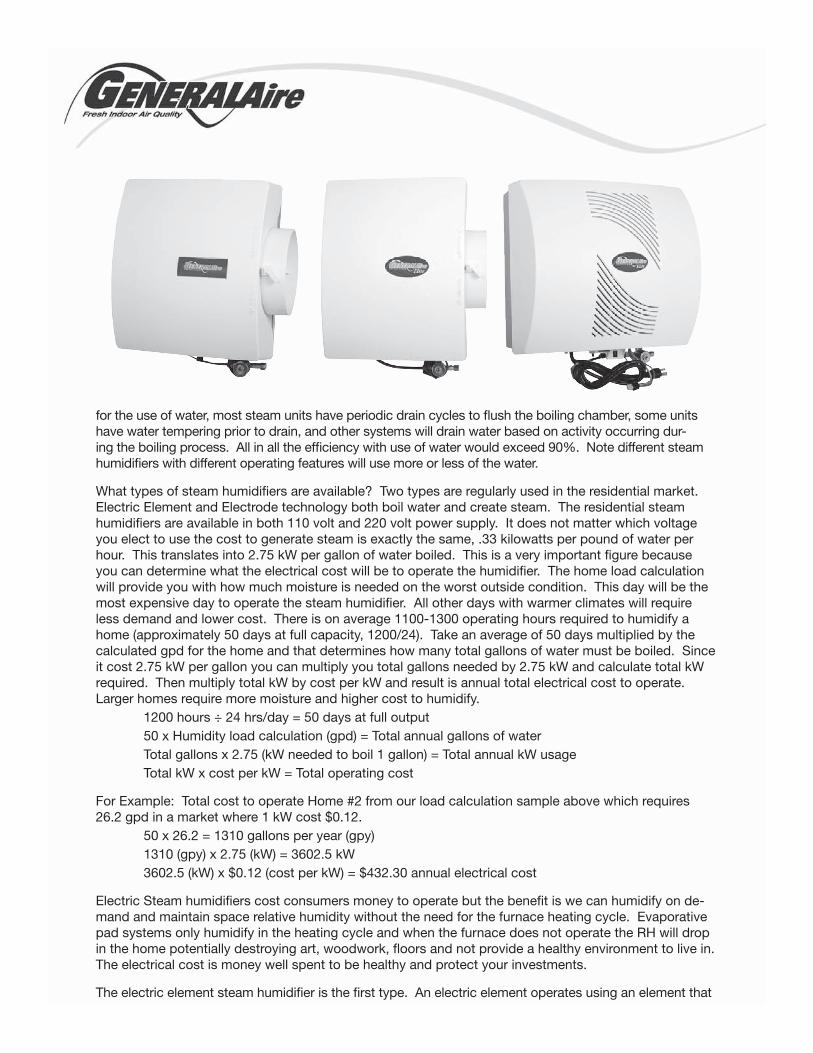
What types of steam humidifiers are available? Two types are regularly used in the residential market. Electric Element and Electrode technology both boil water and create steam. The residential steam humidifiers are available in both 110 volt and 220 volt power supply. It does not matter which voltage you elect to use the cost to generate steam is exactly the same, .33 kilowatts per pound of water per hour. This translates into 2.75 kW per gallon of water boiled. This is a very important figure because you can determine what the electrical cost will be to operate the humidifier. The home load calculation will provide you with how much moisture is needed on the worst outside condition. This day will be the most expensive day to operate the steam humidifier. All other days with warmer climates will require less demand and lower cost. There is on average 1100-1300 operating hours required to humidify a home (approximately 50 days at full capacity, 1200/24). Take an average of 50 days multiplied by the calculated gpd for the home and that determines how many total gallons of water must be boiled. Since it cost 2.75 kW per gallon you can multiply you total gallons needed by 2.75 kW and calculate total kW required. Then multiply total kW by cost per kW and result is annual total electrical cost to operate. Larger homes require more moisture and higher cost to humidify. 1200 hours ÷ 24 hrs/day = 50 days at full output 50 x Humidity load calculation (gpd) = Total annual gallons of water Total gallons x 2.75 (kW needed to boil 1 gallon) = Total annual kW usage Total kW x cost per kW = Total operating cost
For Example: Total cost to operate Home #2 from our load calculation sample above which requires 26.2 gpd in a market where 1 kW cost $0.12. 50 x 26.2 = 1310 gallons per year (gpy) 1310 (gpy) x 2.75 (kW) = 3602.5 kW 3602.5 (kW) x $0.12 (cost per kW) = $432.30 annual electrical cost
Electric Steam humidifiers cost consumers money to operate but the benefit is we can humidify on de-mand and maintain space relative humidity without the need for the furnace heating cycle. Evaporative pad systems only humidify in the heating cycle and when the furnace does not operate the RH will drop in the home potentially destroying art, woodwork, floors and not provide a healthy environment to live in. The electrical cost is money well spent to be healthy and protect your investments.
The electric element steam humidifier is the first type. An electric element operates using an element that
is submerged in water and heated. The heat from the elements warms the water to a boil and the steam is absorbed into the air steam of the HVAC system. These units are either mounted under the duct, in the duct or next to the HVAC system with a steam distribution tube located in the duct work. The principal of the operation is to fill the boiling chamber to the full probe, energize the elements, boil off water and refill the chamber with water. Never letting the chamber run dry and always filling to the top. Water level is commonly measured using a float. Electric Element is a simple on/off system. Meaning it is either boiling water at maximum output or not operating at all. An electric element humidifier must also be maintained. The mineral that is dissolved in the water will become sediment in the boiling chamber when the water is boiled off. This mineral will cling to the inside of the boiling chamber as well as the elements. As mineral content in the chamber and on the element builds it will absorb the heat being generated by the electric element and reduce the efficiency of the humidifier. Since additional heat is absorbed by the mineral that energy is no longer boiling water, it is heating the mineral thus resulting in lower efficiency. Therefore elec-tric element units begin operation around 97% efficient and loose efficiency on a straight line until cleaning is required. Once there is a large deposit of mineral in the chamber it will cause the element to overheat and require cleaning. Electric element units are currently the most common steam humidifier in the Resi-dential housing market but are now competing more with the second type of steam humidifier, Electrode.
Electrode steam humidifiers do not use an electric element; rather they use electrode plates to pass current thru the water. The electrode type unit uses the mineral laden water as a conductor to pass electrical current from one electrode to another. The transfer of the current through the water generates resistance, creates an amp draw, and produces heat. The heat generated will increase the tempera-
ture of the water to a boil creating steam. Electrode systems are also referred to as replacement canis-ter steam humidifiers because the electrodes are housed in a plastic canister and when the system can not longer reach a targeted amp draw the canister will need to be replaced. The replacement time of the canister will vary due to water conditions and output demand on the humidifier. Electrode technol-
ogy has been available for over 30 years and is commonly used in commercial applications. Electrode humidifiers have advanced controllers because they are not just energizing an element to heat the water they are monitoring the activity in the canister based on electrical amp draw. Since all water varies with mineral content and water conductivity every unit will have to adjust to the conditions it is being oper-ated in. The adjustments come from how much water to put in the canister to reach targeted amp draw (humidity output) by exposing more or less electrode, as well as draining and filling based on activity in the canister. Each electrode steam humidifier manufacturer has proprietary algorithms to operate the humidifier and generate steam as efficiently as possible. Most systems have programmed logic to ac-tivate an alarm when the canister is exhausted and can no longer meet the target amp draw. Requiring the canister to be replaced by a qualified HVAC technician. Electrode humidifiers are steam generating units that mount near the HVAC system and distribute the steam to the duct work using steam hose and distribution nozzle. Electrode steam humidifiers allow manufacturers to build larger capacities while still maintaining a small footprint. Also the installing contractor can quickly replace a canister rather than having to clean and replace part on an electric element system.
Steam humidifiers are by far the only humidifier system that can maintain relative humidity in homes. The output is not limited to or tied to the furnace heating cycle and homeowners can maintain rh in the space regardless of where the thermostat has been set day or night. If the consumer is concerned about their IAQ in the home and wants to preserve their valuables steam is the answer.
“Electric element units are currently the most common steam humidifier in the Residential housing market but are now competing more with the second type of steam humidifier, Electrode.”
Humidification SelectionSteam or Evaporative Pad? The homeowner requirements will play a major role in the selection of hu-midifier. Questions need to be asked, are there health reasons for a humidifier, protection of valuables, static electricity, and all the things discussed earlier in this training manual. If the homeowner has hard wood floors, artwork, musical instruments then it is imperative they protect the household valuables, steam is the best. Explain to the decision maker why they need humidity and find out what their hot buttons are. If someone has a small place and would like to keep the residence above 30% you could consider an evaporative pad type humidifier. This technology would allow the homeowner to maintain low levels of RH. When you approach homes that are in excess of 2000 s/f and above most likely an evaporative type unit will not maintain rh in the winter months. It will add moisture but performance will be affected by furnace cycles. For larger homes it is strongly urged to promote and sell steam. Perform a load calculation and only sell the capacity humidifier that meets or exceeds this calculated number. Under sizing a humidifier will only result in unhappy consumers. For applications using Heat Pumps the only choice is steam. As discussed earlier there is not enough energy in the air to allow evaporative type systems to perform on a heat pump. Steam is your answer.
All in all any type humidifier is better than none at all. Point out the advantages of humidification, take advantage of protection of valuables you see in the home, discuss health for children, and make the homeowner realize it is a good investment. If you do not ask you will not sell.
Humidifier InstallationInstallation of all humidifiers is critical in the performance of the system. Installed improperly will result in unsatisfied homeowners and poor performing humidifiers. We will review installation of Evaporative Pad type systems as well as steam. Since there are many manufacturers of humidifiers, the goal is to discuss general installation procedures that are common among the technologies. It is very important the installer read and review the installation manual provided by the manufacturer. Failure to install equipment within the manufacturer’s guidelines usually will void the equipments warranty and is the sole responsibility of the installer.
Evaporative Pad System Installation
The installation of by-pass and power fan evaporative humidifiers will be the focus of this manual. Re-minder evaporative systems are recommended for installation on forced air HVAC systems generating 120° or higher supply air.
By-pass type humidifiers are the most common pad system and come in a variety of gpd outputs. Installation guidelines are similar for all capacities. A by-pass humidifier is exactly as described in the name, warm air is by-passed from the supply duct across the wet pad and ducted back to the return air of the HVAC system. Commonly supplied parts with a by-pass humidifier include the humidifier, humi-distat, water tap, and transformer. Items that installer will need to supply include humidistat wire, flex duct, wire ties, round duct connector, current sensing relay (if required), and mounting screws.
Step 1: Since air is being by-passed from supply to return the installer must select hanging the humidifier on either supply or return duct. It does not matter which is selected. Select the duct that provides the most access and will not interfere with other IAQ products.
Step 2: Use the proper templates provided with instructions and cut an opening in the duct for the humidifier to mount over.
Step 3: Mount the humidifier on the duct.
Step 4: Select a location on the opposite ductwork, of the humidifier, for the air to by-pass. If the humidifier is located on the return, the flex duct will attach to the supply side.
Step 5: install round flex connector on the duct for the by-pass air to be connected.
Step 6: Connect the humidifier to the round connector using appropriate size flex duct and secure using wire ties and/or tape.
Step 7: Locate home water line to connect water supply valve.
Step 8: Connect humidifier supply water to the unit.
Step 9: Connect humidifier drain line to condensate pump or home drain.
Step 10: mount the humidistat in the conditioned space on the return air duct prior to the humidifier. The air being measured must be prior to adding moisture.
Step 11: Wire the humidistat, transformer and optional control devices per the installation manual.
Step 12: If optional outdoor air sensor is provide, install sensor and run wire from humidistat to out-door sensor.
Step 13: Turn the HVAC on in the heating mode and test the operation of the humidifier.
Power Fan Humidifier installation is very similar except by-pass flex duct is not required because the humidifier will bring air across the media with a built in fan.
Step 1: Locate humidifier on the supply side (warm air side) of the furnace and use the proper tem-plates provided with instructions and cut an opening in the duct for the humidifier to mount over.
Step 2: Mount the humidifier on the duct.
Step 3: Locate home water line to connect water supply valve.
Step 4: Connect humidifier supply water to the unit.
Step 5: Connect humidifier drain line to condensate pump or home drain.
Step 6: Mount and wire the humidistat in the conditioned space on the return air duct prior to the AHU.
Step 7: If optional outdoor air sensor is provide, install sensor and run wire from humidistat to out-door sensor.
Step 8: Provide a 110 volt outlet at AHU for humidifier power supply.
Step 9: Select control wiring from installation manual that best suits application.
Step 10: Turn the HVAC on in the heating mode and test the operation of the humidifier.
Steam System Installation
We will discuss installation of a steam humidifier using a distribution nozzle in the duct work. It is the safest and most flexible installation to avoid operational difficulties which are created mainly by poor installation. Installation of a steam humidifier requires some additional thought to location of unit, steam nozzle location, steam hose route, and air flow safety device. When the right decisions are made the installation is smooth and the operation of the unit is optimized. As each step is listed there will be sig-nificant details and information provided. There will be choices that must be made and the easiest is not always the best.
Step 1: Determine where you will locate the steam distribution nozzle in the ductwork. The distribu-tion nozzle must be located in the duct with the following parameters; a) There must be 36 inch-es of straight duct down stream of the nozzle with NO offshoots, bends, Ts, elbows…. b) There must be laminar airflow at the location of the nozzle. c) Location can be either return or supply duct. Fact, once the steam is absorbed in the 36 inch distance it can NOT cause any wetting. There is only one way to remove moisture from the air, after it has been absorbed, and that is to drop the temperature below dew point. This will only occur across an active AC coil which is not in use during the winter. Therefore the return duct is a prime location for the nozzle.
Step 2: Mount the humidifier on a wall as close to the nozzle as possible using the provided tem-plate. The humidifier needs to be mounted level on the wall. A wall might need to be construct-ed to keep the humidifier near by. Keep in mind the following conditions; a) the shorter amount of steam hose that can be used the better the install. Steam is 213 degrees and becomes hot water at 212 degrees. It is best to avoid long steam hose runs to reduce condensate. Also it is atmospheric steam (no pressure) and prefers to rise not run horizontal. b) The steam hose running from the humidifier to the nozzle must maintain a 20% slope back to the unit. Therefore locate the humidifier low enough to meet the slope requirement.
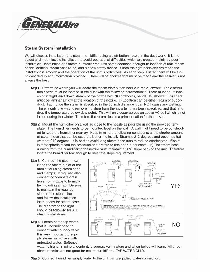
Step 3: Connect the steam noz-zle to the steam outlet of the humidifier using steam hose and clamps. If required also connect condensate drain hose from nozzle to humidi-fier including a trap. Be sure to maintain the required slope of the steam line and follow the installation instructions for steam hose. The diagram to the right should be followed for ALL steam installations.
Step 4: Locate home tap water that is unconditioned to connect water supply valve. It is very important to sup-ply steam humidifiers with untreated water. Softened water is higher in mineral content, is aggressive in nature and when boiled will foam. All three characteristics are not good for steam humidifiers. TAP WATER ONLY.
Step 5: Connect humidifier supply water to the unit using supplied water connection.
Step 6: Connect drain line to humidifier using specified material to meet operational characteristics of humidifier manual. Run the drain line to an open drain or condensate pump. Note that not all manufacturers temper the 212 degree water to levels below 140 degrees as code requires. If the humidifier is not tempering the water than cpvc or copper must be used for drain lines. Also you can not run 212 degree water to a standard low temperature condensate pump. All units that due true tempering is safe to connect to standard condensate pumps. Do not undersize drain lines, this could cause back pressure and not allow the humidifier to drain resulting in possible unit failures. Again follow installation manual for specific instructions for trapping and pipe sizes.
Step 7: Power supply lines are required to be installed per local code and installation instructions. Humidifiers are considered appliances and most have received agency approval using this stan-dard. Therefore ALL humidifiers are required to be installed on separate electrical circuits using specified breaker and wire size. Connect wires to humidifier power supply connections along with ground wire. It is a good installation practice to provide an electrical disconnect at the hu-midifier for service and convenience to consumer.
Step 8: Air Flow switch installation. All steam humidifiers should have air flow proving device installed on the HVAC duct. Most manufacturers require air flow switched to be installed while others just recom-mend or do not require at all. The purpose of the switch is to verify air flow is moving in the duct. If there is no air flow and the steam humidifier is operating, the duct will fill up with steam (like a steam sauna) and condense on the duct and grills. Most likely will results in wet walls and floors at the reg-isters. It is a safety device that needs to be installed for a professional installation. Air flow proving devices vary in style and should be connected to the safety circuit of the humidifier (AB/AB circuit). It is also strongly recommended to wire the safety on the condensate pump in series with the air flow switch. This assures that if either safety device would fail the circuit would open and the humidifier would cease operation until the circuit closes.
Step 9: Fan relay circuit wiring. A portion of the manufacturers now include a dry contact for energizing the fan (R to G) on the AHU circuit board. This will enable the humidifier to operate regardless of the furnace heating cycle. It is a simple 2 wire connection from the humidifier to the AHU circuit board. If the humidifier being installed does not have a relay then it is suggested to install a third party relay to power the fan when there is a call for humidity. Since an air flow device is used the fan must be running for the humidifier to begin steam production.
Step 10: Humidistat installation. Locate the humidistat in the conditioned space or return air supply duct prior to the humidifier. Mount the humidistat to wall or duct and run stat wire from the humidi-fier to the humidistat. Some humidifiers have an on board 24 volt power supply while others will require 24 volt to be wired from the furnace. Connect the dry contacts from the humidifier to the humidistat. Also connect the outdoor air compensation sensor to the humidistat as well, providing the homeowner prefers to operate in the automatic mode.
Step 11: Energize the humidistat and test run the humidifier. Sequence of operation might be as fol-lows; humidistat closes calling for steam production, humidifier closes fan relay, air flow device closes after AHU fan is running, unit begins steam production by filling with water. After the hu-midistat is satisfied the humidifier will stop steam production, open fan relay and remain idle until another call for humidification. During the test cycle verify there are no water leaks in supply and drain lines.
It is imperative that the installation manual is reviewed from front to back for all humidifier installations. Each individual manufacturer has requirements that must be met and is outlined in the manual. Also all electrical and plumbing installations must be to national and local codes. Installation is not difficult but if done improperly can cause many service issues with both steam and evaporative pad humidifiers.
Humidifier MaintenanceAll humidifiers require maintenance. If humidifiers are not maintained they will not add moisture to the air. Maintenance is normally 1 time per year but under special circumstances could be multiple times per year, pending on humidifier type and manufacturer. Maintenance is required because when water is evaporated in to the air, the dissolved minerals in the water are left behind. These minerals build up and eventually cause the humidifier to no longer perform.
Evaporative Pad Humidifier Maintenance
Maintenance requirements for pad type systems consist of pad replacement either annually or semiannually. Again each manufacturer has recommended pad replacement schedules. The reason for the maintenance is the pad is no longer capable of holding water and the water runs off the pad immediately and the warm air is not able to absorb the water. This is caused by either the pad drying out over the summer months or the build up of mineral over the pad from operation. The media can be replaced by completing the following steps.
Step 1: Remove cover of the humidifier.
Step 2: Remove the frame housing the pad.
Step 3: Open the frame and remove pad.
Step 4: Check to make sure bottom of frame around drain is free from obstructions.
Step 5: Clean water trough or tray where water is dispersed from the frame to the pad.
Step 6: Insert new media and reassemble frame.
Step 7: Reinstall the frame/media and put the cover back on the humidifier.
Step 8: Make sure damper is open for humidification.
Step 9: Turn off water to the humidifier, remove the water connection at the solenoid and clean water inlet strainer.
Step 10: Reconnect the water and open the water valve.
Step 11: Test run to make sure no leaks and proper operation.
Steam Humidifier Maintenance
Maintenance for steam units will vary pending on the technology of the humidifier. Some steps are com-mon for all types while others are not. Maintenance schedule for steam units will vary with type and manu-facturer. While some are annual others have notification lights or LCDs for required maintenance which display only when the system requires servicing. It never hurts to look at a unit even if it is not displaying service notification. Service steps and requirements for both element and electrode steam will be outlined. Service on steam humidifiers should take approximately 1 hour for both technologies. Electrode units require less cleaning and therefore could only take 30 minutes.
Electric Element Humidifier Maintenance
Element humidifier require routine maintenance and service the mainly consists of cleaning parts and boiling tank of mineral buildup. There is potential for part replacement if any internal component can not be cleaned for proper operation. This service is usually recommended annually or the humidifier has a notification system alerting for service. It is possible maintenance could be required 2 or more times during a humidification season, especially if the unit is undersized for the home it is humidifying. Basically the unit will run constantly when undersized, not meeting space demand and building up mineral in the chamber more quickly. If maintenance is not done the element could fail and need replacement.
Step 1: Manually drain humidifier
Step 2: At humidistat, change to off mode.
Step 3: Turn off power to humidifier.
Step 4: Turn off water to humidifier.
Step 5: Remove humidifier boiling chamber per manufacturer’s instructions.
Step 6: Clean tank and drain outlet on tank.
Step 7: Carefully clean the heating elements. NOTE: If you break and element during cleaning it must be replaced and is not considered a failure under warranty.
Step 8: Clean water level float to assure it moves freely to engage and disengage water fill.
Step 9: Clean inlet water strainer.
Step 10: Clean drain line and trap to make sure mineral has not clogged or reduce flow of drain water.
Step 11: If using a condensate pump, clean tank to remove any mineral that could be deposited in holding tank.
Step 12: Reassemble the humidifier and connect all water and drain lines.
Step 13: Turn water on.
Step 14: Turn power on.
Step 15: Turn humidistat on.
Step 16: Test the humidifier to assure proper operation.
Electrode Humidifier Maintenance
Electrode steam humidifier maintenance involves less cleaning but does require a replacement boil-ing canister which contains the electrodes. Most electrode humidifiers will include a notification display on the unit requiring cylinder replacement. This notification occurs when the canister can no longer reach target output, based on amp draw. The controller realizes this lack of amperage and triggers the system to require a cylinder replacement. This replacement could be annually or even longer depending on demand output on the humidifier and water quality. Again if the humidifier is undersized the system could operate 24 hours a day and require a cylinder replacement in a matter of months. Properly sized systems should operate for a humidification season under normal water conditions.
Step 1: Manually drain humidifier
Step 2: At humidistat, change to off mode.
Step 3: Turn off power to humidifier.
Step 4: Turn off water to humidifier.
Step 5: Remove electrode canister by disconnecting electrode leads, steam hose, and fill probe connection.
Step 6: Discard canister. DO NOT OPEN AND CLEAN.
Step 7: Remove drain valve and clean plunger.
Step 8: Insert new O-ring, provided with new canister, in drain valve.
Step 9: Replace washer spacer over o-ring on drain valve.
Step 10: Insert new canister and reconnect, fill probe, electrode leads and steam hose.
Step 11: Remove water connection at humidifier and clean inlet water strainer.
Step 12: Clean drain line and trap to make sure mineral has not clogged or reduce flow of drain water.
Step 13: If using a condensate pump, clean tank to remove any mineral that could be deposited in holding tank.
Step 14: Reassemble the humidifier and connect all water and drain lines.
Step 15: Turn water on.
Step 16: Turn power on.
Step 17: Turn humidistat on.
Step 18: Test the humidifier to assure proper operation.
References
Excerpts taken from Section 1, 2, and 3 Carel LLC, Carel Paper +03U220725r0_0
Indirect Health Effects of Relative Humidity in Indoor Environments. Environmental Health Perspectives, Vol. 65, p358. Sterling, et.al. 1986.
The complete study is also available at http://ehp.niehs.nih.gov/members/1986/065/65050.PDF
Study materials researched and written by Dean Schuerich, Decemeber 23, 2009
Disclaimer
Basic Humidification 101 is intended to provide information about Whole-House Humidifcation Sys-tems. Users of this document must keep abreast of rapid changes in technologies, standards, and mandates as applicable to federal, state, provincial, and local laws and regulations.
In publishing this document, General Filters, Inc. is not undertaking to render scientific, professional, medical, legal, or other advice or services for or on behalf of any person or entity or to perform any duty owed by any person or entity to someone else. Any and all use of our reliance upon the ma-terials for education purposes is at the user’s own discretion and risk. Anyone using this documrnt should rely on their own independent judgement or, as appropriate, seek the advice of a competent professional in determining the exercise of resonable care in any given situation.