basic ohm’s law - mississippi state university
TRANSCRIPT
Basic Ohm’s Law ABE 3413 – Bioinstrumentation I Dr. Filip To Ag and Bio Engineering, Mississippi State University
A Little Formula – the Ohm’s Law
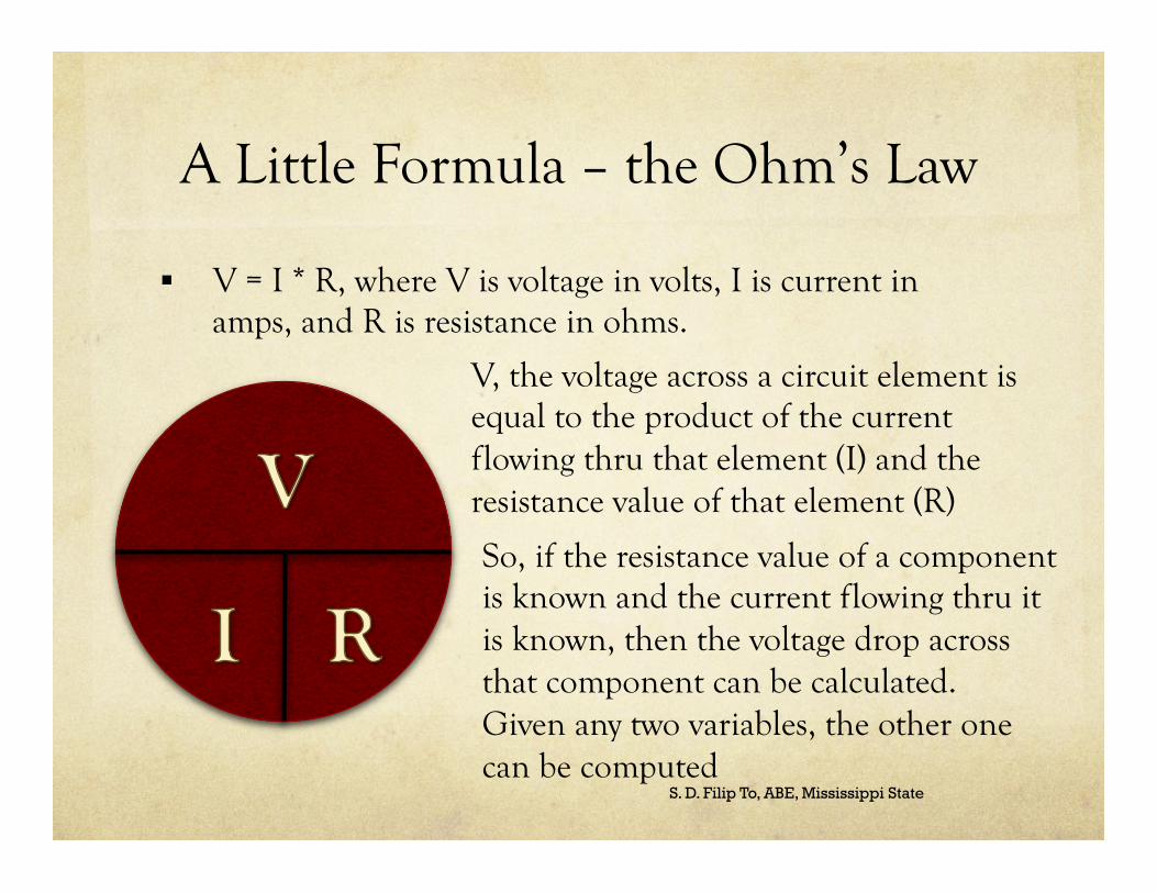
§ V = I * R, where V is voltage in volts, I is current in amps, and R is resistance in ohms.
S. D. Filip To, ABE, Mississippi State
V, the voltage across a circuit element is equal to the product of the current flowing thru that element (I) and the resistance value of that element (R)
So, if the resistance value of a component is known and the current flowing thru it is known, then the voltage drop across that component can be calculated. Given any two variables, the other one can be computed

The Other Ohm’s Law
§ P = Power in Watt, V = voltage in volts, I = current in Amp
§ Power = Energy/Time (Watt = Joule/Sec)
§ Observing this formula and the one in previous slide, we know the relationships between P, V, I, R
§ P = V * I
§ V = P / I
§ I = P / V
§ P = I2 * R
§ P = V2/R
S. D. Filip To, ABE, Mississippi State

Constructing a Circuit
§ How do you implement a circuit described in a schematic diagram?
§ How do you measure voltage?
S. D. Filip To, ABE, Mississippi State
The easiest and clean way to construct a circuit is to use a
BREAD BOARD

Bread Board
S. D. Filip To, ABE, Mississippi State
BREAD BOARD
Internal of a bread board
The black hole patterns are conductors (copper)
Components plugged into the holes of the same conductor are
connected to each other

Constructing a Circuit with Bread Board
S. D. Filip To, ABE, Mississippi State
R1
R2
R3

Measuring Voltage
S. D. Filip To, ABE, Mississippi State
Multi meter
Measuring VAB Red on A, Black on B
Measuring VDB Red on D, Black on B

Examples Given the circuit on the left. Assume the voltage of R2 = 4 volts. 1. What is VR1, and VR3? 2. What is the total power produced by the power source? 3. What is the power consumed by R3?
VR2 = 4 volts; VR2 = IR2 * R2; IR2 = VR2/R2 = 4 A; Draw the current in the circuit, the current thru R1 = the current thru R3 = current thru R3. VR1 = IR1 * R1 = 4 A * 1 Ohms = 4 volts. Since R3 is = R1 then VR3 = 4 volts.
P = V * I. The voltage of the source = 12 volts, the current from the source is 4A so PV1 = 4 A * 12 V = 48 watts.
PR3 = VR3 * IR3 = 4 volts * 4 A = 16 watts
REMEMBER UNITS WHEN YOU DO MATH WITH QUANTITIES!!!

Homework Due Next Class
1. Based on Ohm's Law, if a circuit component is consuming 0.12 watts of power and there is a voltage drop of 1.2 volts across it, what is the resistance of this circuit in the correct unit?
2. Assume that there is a resistance of 2.70 kΩ in a system and there is a current of 2.2 A flowing thru it. How much energy is consumed by this component in 24 hours?
3. Imagine a circuit consisted of two DC power sources of 12 volt and 10 volts. The negative terminals of these power sources are wired together. Assume that the positive terminals of these power sources are labeled as A and B respectively. It is desired to connect nodes A and B with a resistance element so that the power dissipated by it is 20 watts. What is the value of resistance must be chosen for this?
4. Assume that you have two DC voltage sources of 1.5 volts each (like two AA batteries). The positive terminals are wired together (joined together) and the negative terminals labeled A and B respectively. What is the voltage from A to B?
5. For problem 4, what is the current if nodes A and B are connected with a resistor of 1 ohm?
S. D. Filip To, ABE, Mississippi State