basic principles of networking - about us
TRANSCRIPT
Basic principles of networking

2
Networks
communication network: nodes and links
nodes:
– user device; other endpoints;
– intermediate networking nodes routers, switches, multiplexers, mobile network nodes
• in general, these are also computers
• have to be fast
– physical nodes: a device
– logical nodes: a function
links: – provide interconection of nodes
– physical links
– logical links

3
Digital transmission:
– the information to be transmitted (e.g. picture, text,
voice, etc.) is converted into binary data
– binary data is transmitted over the network
binary data:
– series of zeros and ones
basic element:
– bit, eight bits is a byte or octet in communications
E.g.
– letter A: 01000001;
– one 125 microsec segment of voice: 01011100
Digital communications

Digital communications
The data is organised into
– frames or packets
Frame or packet header
– information for network elements, what to do with it
– body: the actual data
Digital communications
Error detection and correction
– possible with advanced mechanisms
Acknowledgement
– receiver acknowledges the correct receipt of a frame
Retransmission
– in case of error
Digital communications
to transmit digital information, phyisical signals are needed
digital signals:
– can change in given instants
– can have a finite set of possible values
transmission bitrate:
– the amount of information that can be transmitted in a second
• bps, kbps, Mbps, Gbps: x1000 in telecom.
– x1024 in IT
• e.g. 1 Gbps Ethernet link: approx. 61000 pages of text in a second

Digital communications
capacity
– of a link: amount of bits that can be transmitted in a
second
– of a node: amount of bits that can be
processed/forwarded in a second
user bitrate
– how many bits a user want to transmit
– or how many bits it can transmit

8
Circuit switching (CS)
circuit switched transmission/network
– originates in telephony
– in old analogue phone systems a metallic circuit was
physically created between the two endpoints
– in so called cross-bar switches: metallic wires/bars
were crossed to connect in/outputs of telephone
exchanges

9
Circuit switching (CS)
circuit switched digital communications
– before the actual stream of user data, there is a signalling phase of the communication, to set up the connection
– signalling: user and network nodes exchange information in order to set up the connection and required network resources, capacities on all links between the two endpoints
– the flow of data uses the aforementioned network resources/capacities along the path in the network
– the actual communication may „last forever”
– frames contain user data
– connection is teared down by explicit signalling

10
connection established
data flow over the
connection
Circuit switching (CS)
11
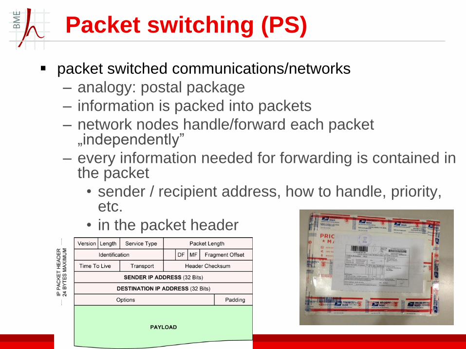
packet switched communications/networks
– analogy: postal package
– information is packed into packets
– network nodes handle/forward each packet „independently”
– every information needed for forwarding is contained in the packet
• sender / recipient address, how to handle, priority, etc.
• in the packet header
Packet switching (PS)

12
if a packet is ready, the terminal equipment sends
it to the network
network nodes are responsible for forwarding
based on addresses and other information
the packets are flowing independently in the
network
basically there is no establishment of fixed
connections, capacities along the routes
Packet switching (PS)

13
packets may follow different routes
there is no guarantee that packets arrive in
order: there must be mechanism at the
endpoints to ensure correct order
Packet switching (PS)
14
CS networks traditionally
– typical: voice telephony networks
– central offices, large operators, large infrastructure, own infrastructure (network)
– network centric view: control and charge the whole transmission/process end to end
– centralized, controlled
– fixed, guaranteed service quality
– timely delivery of data is a must
– constant flow of data
– base of charging: connection time
– high availability
CS vs. PS

15
PS networks traditionally
– typical: IP (Internet Protocol) networks
– originating from small scale computer data
networks
– small amounts of sporadically sent data, no need
for timely delivery
– distributed, service remains in case of failure of
various network nodes/links
– user centric view: to ensure interchange of data
without error, don’t care about the network
– base of charging: amount of data
CS vs. PS
16
the two paradigms are mixed in real networks
– existing infrastructure to be used as much as
possible by the operator
Internet Protocol / Ethernet carried over
„classical” circuit switched SDH, or
circuit emulation over Ethernet
or CS (e.g. voice) service over PS
– VoIP
CS vs. PS

17
connection oriented
– there’s a signalling phase for setting up a
connection
• although may be over PS network
• e.g. TCP over IP
connection-less
– no connection setup
CS vs. PS
18
Network services
real time service
– the information should be transmitted when it is created (or with minimum latency)
– e.g. voice call, videotelephone
– quality:
• latency and variance of latency (jitter)
– latency: fraction of second
• packet (information) loss: tolerable
„quasi” real time
– (live) streaming voice and video
– latency can be seconds

19
Network services
non-real time service
– latency is not a concern
• seconds: browsing
• tens of seconds: file transfer, email
– data loss is not permitted
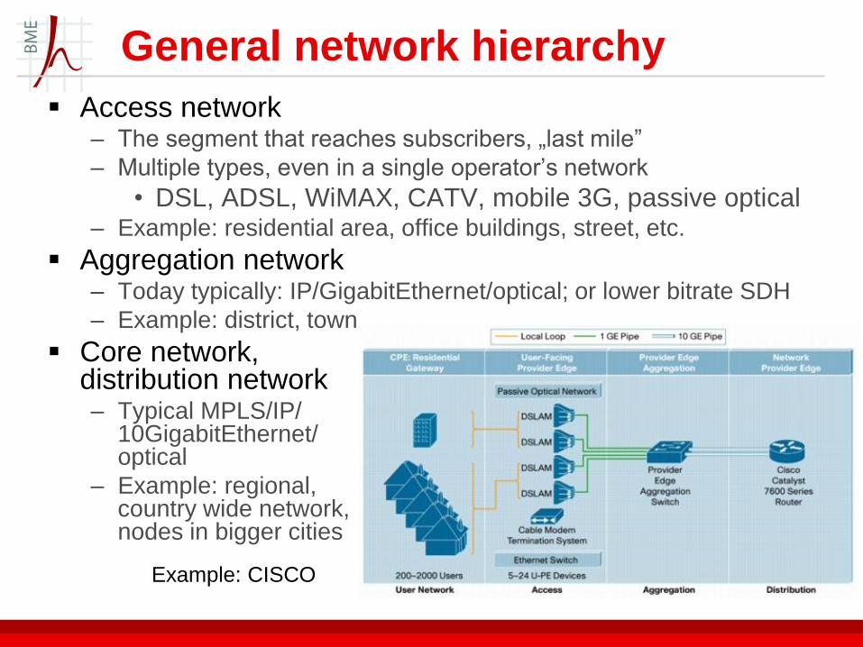
General network hierarchy
Access network – The segment that reaches subscribers, „last mile”
– Multiple types, even in a single operator’s network
• DSL, ADSL, WiMAX, CATV, mobile 3G, passive optical – Example: residential area, office buildings, street, etc.
Aggregation network – Today typically: IP/GigabitEthernet/optical; or lower bitrate SDH
– Example: district, town
Core network, distribution network – Typical MPLS/IP/
10GigabitEthernet/ optical
– Example: regional, country wide network, nodes in bigger cities
Example: CISCO

Geographic scale of networks
Personal Area Network (PAN) : – close to one person, typically extends to 10 meters
– wired PAN: USB and FireWire connections
– wireless PAN: Bluetooth and infrared communication
Local Area Network (LAN): – in a limited geographical area such as a home, school, office building
– wired LANs: most likely based on Ethernet technology (coaxial cables, power lines etc.)
– wireless LAN: 802.11a,ac,ad,b,g,n
– higher data transfer rates; can be connected to a WAN using a router
Metropolitan area network (MAN): – usually spans a city or a large campus
Wide Area Network (WAN): – covers a large geographic area such as a city, country, or spans even intercontinental
distances
– many types of media such as telephone lines, cables, and air waves
– WAN technologies generally function at the lower three layers of the OSI reference model: the physical layer, the data link layer, and the network layer.
26/07/2016 21 © Department of Networked
Systems and Services
22
end to end transmission over a large network
network containing various elements
– different standards, vendors, network solutions
– different access methods, transmission links, etc.
there is a lot of different functions to be solved in
the networks
– these are organized into logical layers
there is an „entity” (software function)
Network layers

layered view of a travel example
– information: me; from: Home; to: Sydney hotel
– passed to end-to-end layer Pacific tours
Network layers
Home Bp. Airport London Singapore Sidney Sidney
Hotel
British
Airways
A320 A380
Quantas
B747
Bp. Taxi
Skoda
Hotel
shuttle
Scania
Pacific tours

24
OSI (Open System Interconnection) seven layer
model contain all functons
– allocated to layers
the first four layers are treated by the networks
– the above three layers are at endpoints
Examples:
– SS7: Signalling System No. 7, over TDM: telephony
network signalling: all 7 OSI layers
– TCP/IP in Ethernet: Layer 1-4 and above
Network layers
Protocol stack (network layers)
Hierarchy of protocols
ISO OSI 7 protocol layers works as general logical separation of functionalities
A protocol usually communicates with two other in the stack (upper and lower layer)
Lower layer protocols provides services for upper layer protocols
Lower layer protocol hides even lower layer protocols/functions from the upper layer protocol → transparency
Lower layer protocols usually encapsulate upper layer protocols
Modularity, „interchangeability” is important

Protocol stack (network layers)
http://www.mobile-telecom-networks.com http://www.comptechdoc.org/independent/
networking/protocol/protlayers.html
27
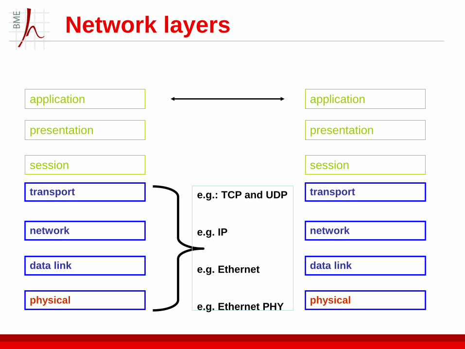
application
presentation
session
transport
network
data link
physical
Network layers
e.g.: TCP and UDP
e.g. IP
e.g. Ethernet
e.g. Ethernet PHY
application
presentation
session
transport
network
data link
physical
28
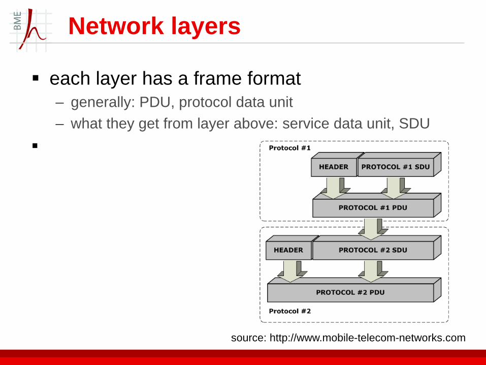
each layer has a frame format
– generally: PDU, protocol data unit
– what they get from layer above: service data unit, SDU
Network layers
source: http://www.mobile-telecom-networks.com

Network layers
PDU, Packet Data Unit:
– Contains the protocol header and the SDU as „useful
information”
Header:
– additional information about how the packet have to be
handled by network and about the SDU
SDU, Service Data Unit:
– PDU of an upper layer protocol or on the top of the
protocol stack, the useful data itself
This mechanism is called encapsulation.
The actual name of SDU depends on the protocol, e.g.
Ethernet’s SDU is called frame, TCP’s SDU called
segment.
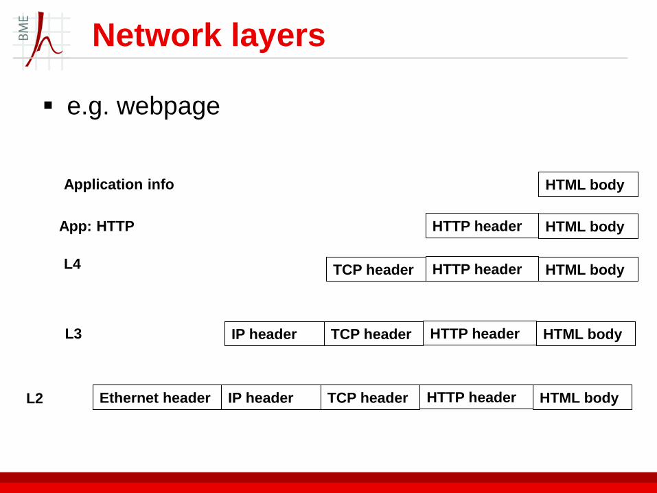
e.g. webpage
Network layers
HTML body HTTP header
HTML body HTTP header TCP header
HTML body HTTP header TCP header IP header
HTML body HTTP header TCP header IP header Ethernet header
Application info HTML body
App: HTTP
L4
L3
L2
31
physical layer (PHY)
actual transmission over the physical medium
– activate, maintain and deactivate the physical connection
– adopting the data stream to physical transmission
– ensure that endpoints of the connection recognize transmission
signals
– creating the actual physical signal
ordered forwarding of bits
mechanism for detecting/correcting bit errors
etc.
Network layers
32
data link control layer (L2)
originally: communication between two, directly interconnected device; organize
creating data frames, detecting frame delimiters, error free and ordered delivery of data frames
detecting errors (lost/erroneous frames), sending and receiving acknowledgements
in case of errors: retransmisions
error free delivery towards network layer
sublayers
– MAC, Medium Access Control: how and when do endoints transmit or receive
– LLC, Logical Link Control: the other functions
– RLC, Radio Link Control: in mobile networks (-> maybe L3)
Network layers
2002. október 25. 33
network layer (L3)
assure end to end delivery in a large (global) network
level
interconnect heterogeneous networks
– e.g. access of Facebook from mobile network
routing of packets or flows in the network
control of network traffic
addressing
Network layers

34
transport layer
end to end error free and in-sequence delivery
– without knowing the details in layers below
– for this:
• error detection,
• acknowledgements and retransmissions
• control of amount of data sent
allowing several communications in paralell by a single
endpoint
Network layers

35
this nice structure is almost never existent
various layers are integrated above each other
more layers
e.g. 4G networks example:
–
Network layers
source: www.nsnam.org
What is protocol?
„…a communication protocol is a system of rules that allow two or more entities of a communications system to transmit information...These are the rules or standard that defines the syntax, semantics and synchronization of communication and possible error recovery methods. Protocols may be implemented by hardware, software, or a combination of both.
Communicating systems use well-defined formats for exchanging messages. Each message has an exact meaning intended to elicit a response from a range of possible responses pre-determined for that particular situation. The specified behavior is typically independent of how it is to be implemented. Communications protocols have to be agreed upon by the parties involved. To reach agreement, a protocol may be developed into a technical standard.” – Wikipedia

Standardization
Organizations:
– IEEE (Institute of Electrical and Electronics Engineers)
• Wifi, Bluetooth etc.
– ITU (International Telecommunication Union)
• xDSL, SS7, JPEG
– 3GPP (3rd Generation Partnership Project), ETSI (European Telecommunications Standards Institute)
• GSM-LTE
Members: 3 main parties
– Vendors: Ericsson, Nokia, Intel, Qualcomm
– Operator/service provider: Telekom, Vodafone, Verizon
– Regulators: NMHH, FCC

Standardization
An implementation of standard must be conform with the
standard
Interoperability: different implementations/products from
different vendors are able to communicate with each
other
Increases the market competition between vendors

Internet protocol
meanwhile in computer networks ...
– local networks of computers
– interchanging files, mails, data
• servers and clients
– autonomous systems (AS)
let’s connect autonomous systems
– as simply and as distributed as possible

Internet protocol
Internet: ~ devices using Internet Protocol
– unified, global addressing method, devices connecting
to the network can be reached through this IP address
– given standard packet format
• more precisely: IP datagram
– given packet forwarding method and routing methods
and supporting mechanisms
– various applications

Internet protocol
a family of protocols using IP protocol packets for transmission
above network layer (3. layer) – transport layer
• TCP Transmission Control Protocol: reliable transfer of files
• UDP User Datagram Protocol: unreliable transfer of streams
• SCTP Stream Control Transmission Protocol – designed to carry telephony signalling
„control plane application” protocols – ICMP Internet Control Message Protocol
– SNMP Simple Network Management Protocol
– IGMP Internet Group Management Protocol: manage multicast
– DHCP Dynamic Host Configuration Protocol: to ask an IP address from a server
Internet protocol
application protocols
– HTTP Hypertext Transfer Protocol
– SMTP Simple Mail Transfer Protocol
– FTP File Transfer Protocol
– TELNET : remote login
– SSH Secure Shell: remote login
– RTP Real Time Protocol: for real time voice/video
– NTP Network Time Protocol: time synchronisation
– SIP Session Initiation Protocol: call signalling
– H323: voice and videoconferencing
– etc, there is a lot

Internet protocol
ICMP IGMP Internet Protokoll,
IP
TCP UDP
FTP, Telnet, HTTP,
SMTP,
physical
datalink: Ethernet, Ethernet over X;
ATM/AAL5, stb.
NFS, SNMP, DNS,
RTP, DHCP
network
transport
ARP
SCTP
WebRTC

Internet Protocol
IP packets, datagrams
– connectionless: no connection setup, etc.
– best effort
– basically no QoS
Later extensions
– means for providing QoS (Intserv, Diffserv)
– means for security (IPSec)

Internet Protocol
version: 4
TTL time to live: decreased by one at each router
protocol: what is carried as payload?
addresses

Internet Protocol
IP networking, „all IP” <-> addressed by IP address
– not a device, but rather a connecting interface of a device
4 bytes: 4 numbers between 0 .... 255
– usually: x.y.z.w, 0<=x,y,z,w<256
– e.g. 152.66.248.74
usually: dynamically and temporarily allocated IP
addresses -> DHCP
other: permanent IP addresses set by the network
operator
– user with admin rights can set in operating systems
IANA: Internet Assigned Numbers Authority

Internet Protocol
first part of the address identifies the network
second part is the device in the network
– e.g. only ~64000 devices can be addressed within
BME
BME network
152.66.z.w
152.66.248.110

Internet Protocol
big networks divided into smaller subnets
the part identifying terminal also identifys subnet
BME network
152.66.x.y
I. E
I.B 152.66.248.v
152.66.249.w
Dept. of Networked
Systems and
Services

Internet Protocol
private addresses, shared address space
– addresses that are only used inside a private network
– not routable to outside the network
– not addressable from outside the network
– create an own mini – internet
• intranet
– everyone at home WiFi (acquiring network address)
• DHCP allocates 192.168.x.y
– e.g. my phone logged in to department server:
• netacc-gpn-5-199-11.pool.telenor.hu
• 84.225.199.11 -> globally visible and accessable
• but I see (Settings/About phone/Status): 100.80.29.135 :
shared address space
Internet Protocol
how/why
– more users/devices than global IP addresses available for
the ISP
– solution one:
• assign when needed one IP address from the pool
• hope that the total number of customers that want to
use Internet is less then the available addresses

Internet Protocol
– solution two:
• use local IP addresses, we can have more
• and expand the namespace visible to outside
• translate between the two: NAT Network Address
Translation
• we don’t gain

Internet Protocol
– solution three:
• expand the namespace: use TCP/UDP port
• use the same IP address for several terminals towards
outside world, with different ports
• this is officiall NAPT Network Address Port Translation,
but we usually call NAT
• it works but there are a lot of problems

Internet Protocol
How to connect autonomous systems
– router
• looks at the Destination address of the IP packet
• routing table:
– Destination Address -> output network interface
– decrements Time To Live field
– voilá
– usually does a lot more
• e.g. Network Address Translation; firewall; packet filtering
• IP security, IP QoS
• IPv4/v6 coexistence
• have various interface (line) cards
• handling of virtual networks
• act as L2 (Ethernet) switch as well, with L2 header processing
• knows a lot of protocols

Internet Protocol
sending between two devices
– in a local network: L2 address can reach the node
– (although the IP address and everything must be
put to the packet, of course)
– packets can be forwarded based on the L2 address
only
if I want to send to a device on my network, I need to
know its L2 address
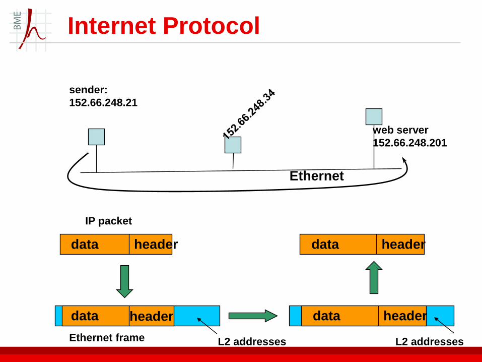
Internet Protocol
web server
152.66.248.201
Ethernet
sender:
152.66.248.21
data header
data header
IP packet
Ethernet frame
data header
data header
L2 addresses L2 addresses

Internet protocols
ARP Address Resolution Protocol
I know the IP address, but what is the Ethernet
address , so to whom should I send in Ethernet
directly?
a broadcast is sent to the network with the
above question
– the one that I searched for answers
– typically: the router
– in Windows: default gateway
Internet Protocol
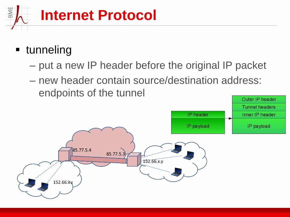
tunneling
– put a new IP header before the original IP packet
– new header contain source/destination address:
endpoints of the tunnel
Internet Protocol
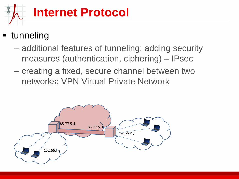
tunneling
– additional features of tunneling: adding security
measures (authentication, ciphering) – IPsec
– creating a fixed, secure channel between two
networks: VPN Virtual Private Network

Internet Protocol
tunneling
– connecting a remote client as if it was in my IP domain
– VPN server in my home network 152.66.. tunnels all
my packets to my IP address 85.77.v.z
– remote server communicates with me through
152.66.x.y

Internet protocols
ICMP Internet Control Message Protocol
– control messages at IP layer, in the payload of
IP packets
– signalling of errors, messages for discovering
routes, paths
– e.g.: ping : ICMP „echo” messages
• check availability of a device
– e.g. traceroute
• show nodes in between two endpoints
Internet protocols
BGP Border Gateway Protocol
– large routers of different network providers can exchange
routing table information with this
– neighbors are configured manually
– there’s a heartbeat messaging to ensure the link is still alive

IPv6
version 6
„new” version (December 1998)
– „IPv4 addresses will be exhausted, IPv6 will spread in the
next 10 years” – random lecturer in 2000; 2010; 2020 ...
why
– IPv4 address exhaustion: only roughly 4.3 billion addresses
– everything on Internet
– can be much better than IPv4
why not
– not backward compatible
– address problem can be handled
• if not solved
IPv6
new IPv6 addresses: 128 bits
2128 possible addresses
– this is a huge number
– but there are restrictions, allocations, etc
most pessimistic allocations estimate around
1500 addresses to each square meters of the
surface of Earth (including oceans)

IPv6
simplified header
security measures built in IP layer
mobility support
– address auto-configuration: device can derive an
own IP address when arrived to a new IP
subnetwork
– permanent IP address <-> temporary IP address
binding in remote nodes
support of IP flows
– to handle IP packet of the same flow identically
– to reserve capacities
– -> ~ provide what circuit switched needs
IPv6
IPv6 is introduced in islands, slowly
mechanisms to interconnect IPv6 domains
over IPv4
several standardized means to solve the
interoperability

IPv6 protocol features
Larger Address Space:
– ~1564 addresses can be allocated to every square meter
of this earth
End-to-end Connectivity:
– Every device will have unique IP address
– every device can directly reach other devices on the
Internet (with some limitations involved)
Simplified Header:
– (header: additional information for proper message
delivery and processing)
– all unnecessary information and options are moved to the
end of the IPv6 header

IPv6 protocol features
Auto-configuration:
– Whenever a node plugs in and wants to be part of a network, IP address information and router information is required to properly configure the node and get it running
– IPv6 supports both stateful and stateless auto configuration mode of its host devices
– stateful – DHCP (Dynamic Host Configuration Protocol):
• host obtains the address as well as other required information such as the configuration information and parameters from a server
– stateless:
• a host can automatically configure its own IPv6 address and does not need any assistance from a stateful address server
IPv6 protocol features
Faster Forwarding/Routing: – the information contained in the first part of the header is
adequate for a router to take routing decisions
• therefore making routing decision as quickly as looking at the mandatory header
IPSec (Internet Protocol Security): – security features for the IPv6 packet: ciphering and
authentication features
– end-to-end: protects all application traffic over an IP network
Mobility: – IPv6 was designed keeping mobility in mind
– this feature enables hosts (such as mobile phone) to roam around in different geographical area and remain connected with the same IP address
– the mobility feature of IPv6 takes advantage of auto-configuration
© Department of Networked
Systems and Services

Transport protocols
TCP Transport Control Protocol – basic goal: to send large (compared to packet sizes)
files/data
• bytestream of data
– it defines a connection-oriented transport over the connectionless IP
– reliable and in-sequence delivery based on the unreliable IP
• acknowledgement/retransmission mechanism
• flow control (load control) mechanism
• two-way data transfer, multiplexing of several higher layer transfers (e.g. file downloads) over single TCP connection
TCP/IP
Transport protocols
role: transmit the data between the actual user
endpoints
TCP packets are called TCP segments
before actual transmission, there is a connection
setup phase
– the two parties agree upon an initial sequence number,
to start with
– signaling of being ready to transmit/receive
ending a connection explicitely
acknowledgement of connection end

Transport protocols
transmission over connection – sliding window mechanism for flow control and
acknowledgement procedure
– ack-ing: receiver tells the sender in the header of TCP segment that what is the last byte received correctly
flow control: – receiver tells the window size: how many more bytes can it
receive
– this enables talking of endpoints with different bitrate and processing rates
• the sender does not overflow the receiver
slow start: initial window size is small and increases
congestion control:
– in case of ACK timeout the sender assumes congestion end smaller window is used
Transport protocols
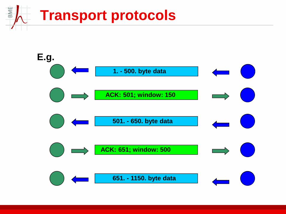
1. - 500. byte data
E.g.
ACK: 501; window: 150
501. - 650. byte data
ACK: 651; window: 500
651. - 1150. byte data

Transport protocols
TCP segment
– source port and destination port: a 2 byte identifier of the
TCP connection
– TCP port + IP address: a network socket
– „server listens to port”: check incoming packets’
Destination Port
– well known ports:
• client should know
in advance
• IANA
• e.g. HTTP: 80
TCP
TCP (Transmission Control Protocol):
– provides reliable, ordered, and error-checked delivery of a stream of octets between applications running on hosts communicating (host-to-host connection) over an IP network
– At the lower levels of the protocol stack, due to network congestion, traffic load balancing, or other unpredictable network behavior, IP packets may be lost, duplicated, or delivered out of order.
– TCP detects these problems, requests retransmission of lost data, rearranges out-of-order data, and even helps minimize network congestion to reduce the occurrence of the other problems. If the data still remains undelivered, its source is notified of this failure.
– Once the TCP receiver has reassembled the sequence of octets originally transmitted, it passes them to the receiving application.

Transport Protocols
UDP User Datagram Protocol
– connection-less transport protocol
– simple, low owerhead
– no flow control, no retransmissions
• UDP packet based
– typically: for small, periodic data units
• voice, video
• better to loose some packets than being delayed
because of the retransmissions
– interesting: connection setup is handled in above
layers in this case
– simply: source port, destination port, error detection
UDP
UDP (User Datagram Protocol):
– simple, connectionless and stateless transmission model
with a minimum of protocol mechanism
– there is no guarantee of delivery, ordering, or duplicate
protection – unreliable
– provides checksums for data integrity
– time-sensitive/real-time applications often use it
– no notification for upper layers about data delivery
Upper layers
DNS Domain Name System
delivery based on IP address
but it is not known in advance, rather a name
– e.g. www.hit.bme.hu <-> IP address ?
to handle the name <> IP address relations
in ancient times it was in a file

Upper layers
hierarchical, distributed directory of names
around the world
DNS concept:
– domains of names
– more domains in domains
• domains are managed by authorities
– name servers for the domains
– supervision: IETF (http://www.i-d-n.net/)
– root name servers
Upper layers
names or domains not necessarily (but often)
mean network/organisational relations
devices of any domain can be distributed
anywhere physically
– e.g. .com domain servers
name servers know the IP address of devices
in the domain
– or the IP address of name servers of
subdomains

Upper layers
example of recursive query
can be query chain

Ethernet
„the” layer 2 of IP networks
– first: local networking technology
• create a small computer network
• coaxial cable
– now: local to metropolitan network sizes
• twisted pair cable in local, optical fibre in metropolitan solutions
Some notions of Ethernet
– 10; 100; 1000 at the beginning means the network operates at 10, 100, 1000 Mbps
– BASE means the type of signaling used is baseband
– 2 or 5 at the end indicates the maximum cable length in 100 meters.
– T: twisted pair, F: fiber; X: duplex
– 1000 Base FX
state of the art: 40 Gbps, 100 Gbps Ethernet links
switches/routers with multiple 40 Gbps Ethernet interfaces

Ethernet
addressing:
– MAC address (often called physical address) of the interface
– 6 bytes, source address, destination address
switching:
– based on destination address, similar to how it is in IP router
– does not consider anything beyond the Ethernet header
– switch learns MAC addresses
no provisioning for QoS or bandwidth allocation
Ethernet
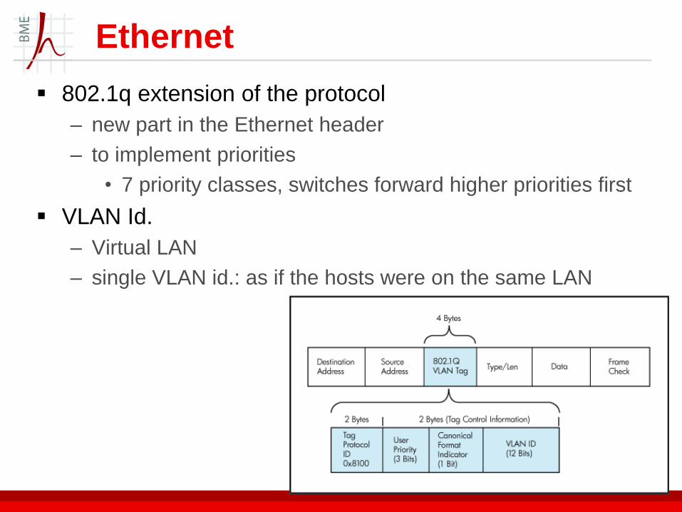
802.1q extension of the protocol
– new part in the Ethernet header
– to implement priorities
• 7 priority classes, switches forward higher priorities first
VLAN Id.
– Virtual LAN
– single VLAN id.: as if the hosts were on the same LAN