basic rabbit laser operation - university of...
TRANSCRIPT

Basic Rabbit Laser Operation

File SetupLayer color is how the Rabbit Software designates different operations so, regardless of design software, you will want to organize geometry into the following layers.
-Cut-Etch-Fill-Material
Note - Each layer needs to be a different color for the Rabbit to process it separately.
For vector based operations, export a .DXF file.
The Rabbit is capable of engraving from a Raster image and the best format for this is .JPG
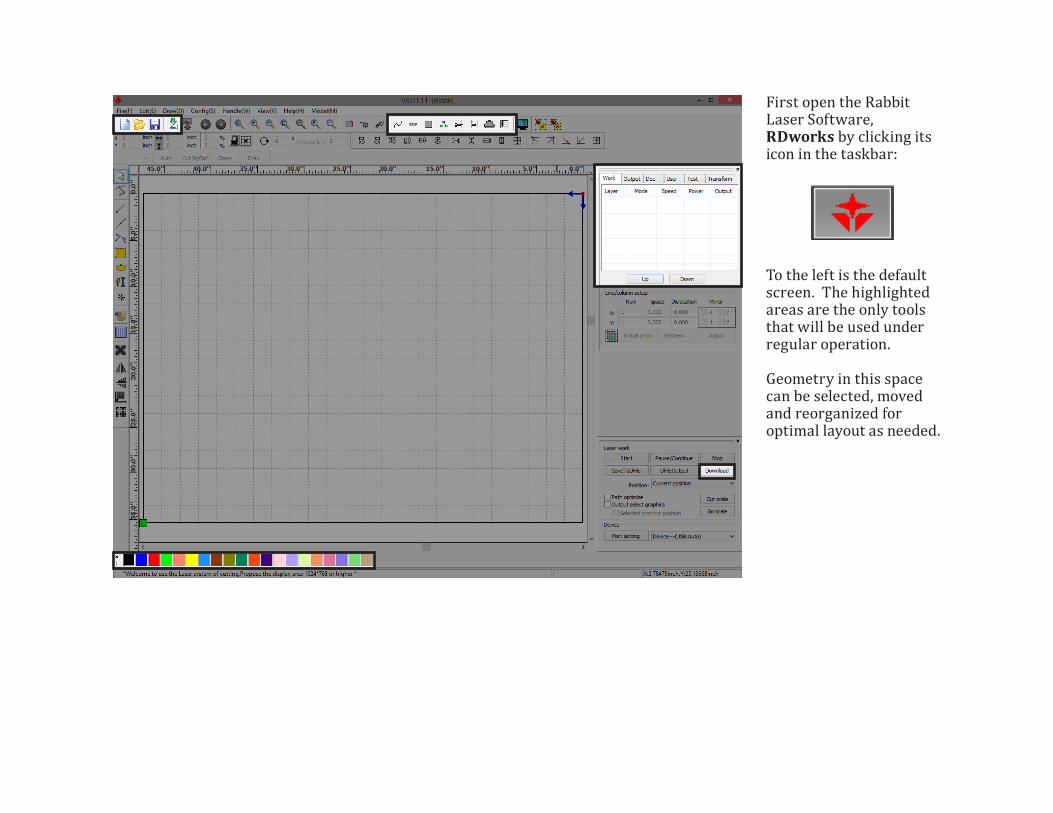
First open the Rabbit Laser Software, RDworks by clicking its icon in the taskbar:
To the left is the default screen. The highlighted areas are the only tools that will be used under regular operation.
Geometry in this space can be selected, moved and reorganized for optimal layout as needed.

Import a FileUse File-Import or click the highlighted button.
Import Invaders.dxf from the RDworks_Tutorial folder.
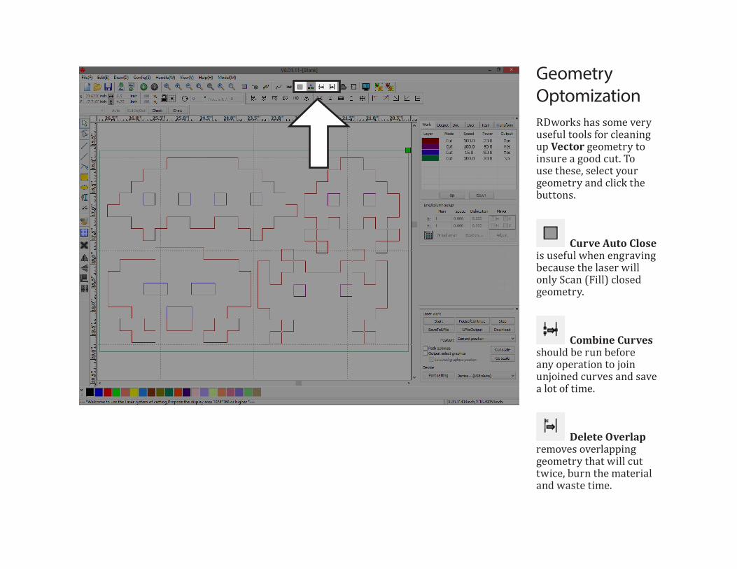
Geometry OptomizationRDworks has some very useful tools for cleaning up Vector geometry to insure a good cut. To use these, select your geometry and click the buttons.
Curve Auto Close is useful when engraving because the laser will only Scan (Fill) closed geometry.
Combine Curves should be run before any operation to join unjoined curves and save a lot of time.
Delete Overlap removes overlapping geometry that will cut twice, burn the material and waste time.

Layer SetupLayers organize both the Settings and the Cut-Order of operations in RDworks.
The layers you set up in your design software will show up on the right, designated by color only. (Layer Names from your design software will not import.)
If you need to change an object’s layer or make a new one, highlight geometry and choose a new color from the bottom of the screen.
To Change the Order of Operations. drag layers up or down.

Setting up a ProcessFirst, click on the layer you want to set up on the right side of the screen.
Layer Parameter is where we adjust the mode, speed and power of the Laser machine. The highlighted windows of this panel are the only options you will need to adjust.
Tip - Order your layers so that the cut out operations happen last because otherwise a cut out part could move in the machine and cause subsequent fill and etch operations to be inaccutrate.

Parameter Library - Preset settings database
Layer - Selects the Layer being set up
Is Output - Determines if layer geometry will be processed
Speed - Determines the speed of the Lens assembly
If Blowing - Turns on or off the machine nozzle air supplyProcessing Mode - Determines process to be run
Min Power - % of Power when speed slows to round corners
Max Power - % of Power when at full speed
Tip - With any laser machine, it is important to run tests on your specific material to determine the optimal settings before you run your job. This is done by making a small square of geometry in RDworks, cutting or scanning it and adjusting the settings based on observation.

Setting Up a Fill OperationThe Parameter Library is where the RPC staff will save settings for different materials. For this fill operation, select RPC Chipboard_Fill from the list and click load.
Tip - Settings in the Layer Parameter often need to be adjusted after testing for optimal results.

Setting the Etch Speed and PowerFor this operation, select RPC Chipboard_Etch from the Parameter Library and click load.
Tip - Settings in the Layer Parameter often need to be adjusted after testing for optimal results.
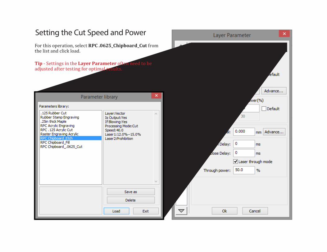
Setting the Cut Speed and PowerFor this operation, select RPC .0625_Chipboard_Cut from the list and click load.
Tip - Settings in the Layer Parameter often need to be adjusted after testing for optimal results.
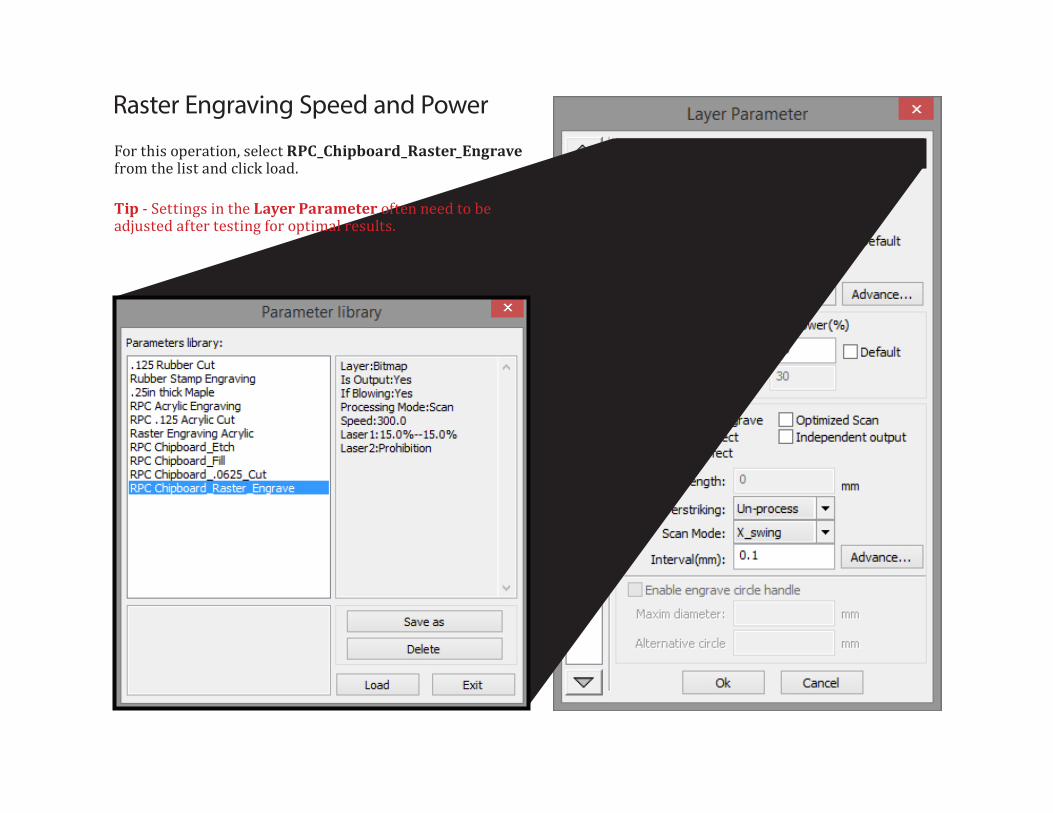
Raster Engraving Speed and Power
For this operation, select RPC_Chipboard_Raster_Engrave from the list and click load.
Tip - Settings in the Layer Parameter often need to be adjusted after testing for optimal results.

Disable the Material Boundary
To ensure the Material Boundary is not cut, first select the Green layer and change the Output to NO.
The machine will recognize all layers, On or Off, as the extents of the geometry and will start its operation from the green dot. This allows parts to be precisely organized on a specific sized material without actually cutting the border.

Start up the Laser Machine
This is the Rabbit Laser Machine Interface. Before turning on the laser, you must first turn on the BOFA Air Purifier and rotate the Compressed Air Valve 90 degrees counter clockwise.
Lift up the Cover, make sure the bed is clear and turn the Laser Machine Key On.
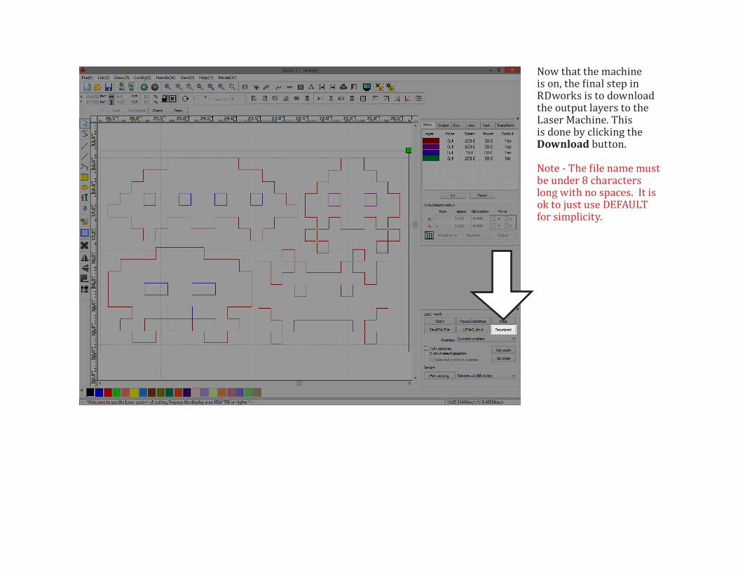
Now that the machine is on, the final step in RDworks is to download the output layers to the Laser Machine. This is done by clicking the Download button.
Note - The file name must be under 8 characters long with no spaces. It is ok to just use DEFAULT for simplicity.

First, place your material so one corner is near the Lens Assembly, the part of the machine pictured below.
Next you must move the bed down so the top of the material is lower than the bottom of the Lens Assembly.
To move the bed up and down, press the Z/U button and then use the left and right Arrows.
Left is Up and Right is Down.
Press ESC to get out of the Z/U control and use all four Arrow buttons to drive the Lens Height Sensor over the material as pictured.
Press Z/U again and use the Down Arrow to highlight Auto Focus.
Press Enter and the bed will raise the material till it is in focus.
2 Focusing the Lens
1 Loading Material
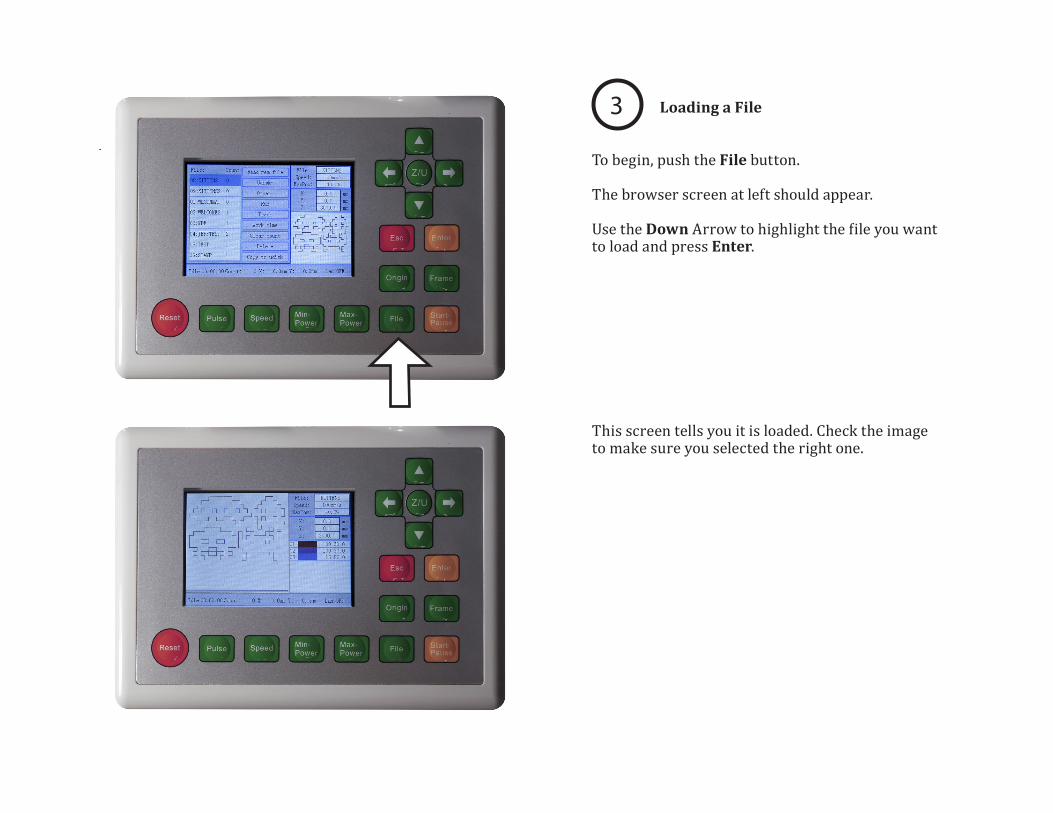
To begin, push the File button.
The browser screen at left should appear.
Use the Down Arrow to highlight the file you want to load and press Enter.
3 Loading a File
This screen tells you it is loaded. Check the image to make sure you selected the right one.

Since materials come in all different sizes and shapes, the machine needs to be told where to begin its operation.
Use the arrows to drive the Lens Assembly directly over the corner of the material that corresponds with the location of the green dot in RDworks.
Once in place, press the Origin Button to lock it in.
4 Setting the Origin
Once your file is loaded, it is helpful to use the Frame button to test the operation. This will drive the lens assembly around the perimeter of your loaded geometry so you can be sure it will cut or engrave in the right place.
5 Test

Be sure to monitor the machine for flare ups or collisions. In the case of a dangerous situation, hit the big red Emergency Stop and the entire machine will be disabled.
If you need to stop for any non-emergency reason such as material that is lifting or if you need to check the quality of a cut, press the Start-Pause button to Pause. If you press Start-Pause again, it will resume exactly where it left off. If you press Esc, the lens assembly will return to your Origin.
7 Operation
When your job is done, remove your material from the bed. If any small parts fall through the grid, they can be retrieved from a small tray that is accessible through the red doors on the front of the machine.
Finally, turn the Key to Off then shut off the air supply and the Bofa Air Purifier.
8 Shut Down
Press the Start button to begin your operation.
6 Start

Advanced Rabbit Laser Operation

Raster Engraving
The Rabbit Laser Machine can perform Raster Engraving from an image file such as a JPEG.
First, import your JPEG file, highlight the geometry and then click the BMP button at the top.

The best settings for this operation are shown here. set the resolution to 200dpi-300dpi and check Dither, Dot Graphic.
Click Apply to View and OK
