basic & simplified controls for machines & systems...2 basic & simplified controls for...
TRANSCRIPT
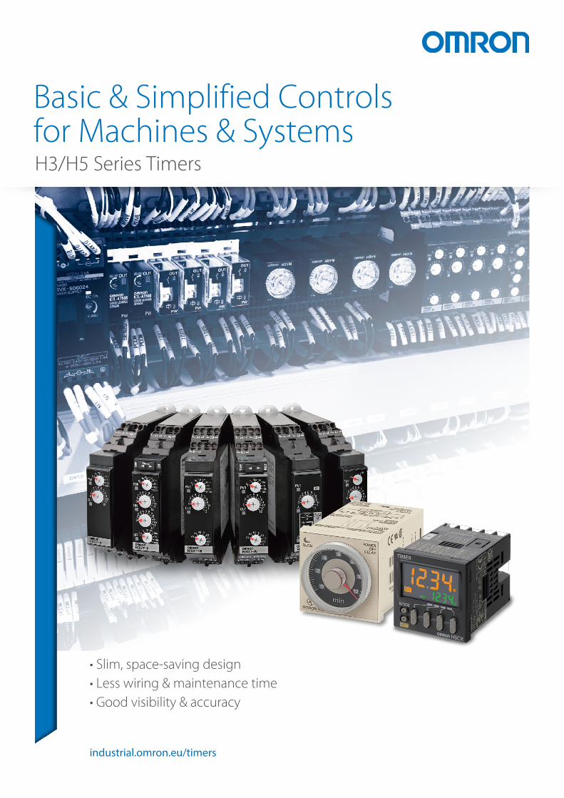
industrial.omron.eu/timers
Basic & Simplified Controls for Machines & Systems
• Slim, space-saving design• Less wiring & maintenance time• Good visibility & accuracy
H3/H5 Series Timers

2 Basic & Simplified Controls for Machines & Systems
80 years of dedication to technology and quality
X-Ray Timer
Continuous improvement is our ethos
It's been 80 years since we produced our first product: an X-Ray Timer. With each new product we provide more value to the customer while leading control panels to a higher level of performance and ease of build.
To pursue the same high quality & best service in the world
As one of the world’s leading suppliers of industrial automation solutions, we not only deploy the latest techniques in our own factories we also practice rigorous quality assurance systems. The result? Products and services you can rely on.
Efficient design
Our CAD library of products (industrial.omron.eu/cadlibrary) saves you time and reduces design effort.
With electical control CAD *Example for Zuken E3.series.
zuken.com industrial.omron.eu/eplan
Design work reduced by 40% to 50%
Previous
E3.series is a product name of Zuken Inc. for their Electrical and Control Cable Design Solution.
Zuken Inc.
EPLAN is a registered trademark of EPLAN Software & Service GmbH & Co. KG.
EPLAN
Download a high-quality your CAD library Partners in panel design
Over
7,000models
Surface Mount Technology (Chip Mounter line)
Assembling lineOmron manufacturing IndonesiaOmron manufacturing Shanghai

3
2016Screw-less Solution
1980Plug-in Small Timer
1962Solid State Timer (Analog)
1954Motor Timer for industry
Development in technology and quality over 80 years
1990Slim Analog Timer
1933X-Ray Timer
When time counts… We're your Timer product solution!
• Wide variety of Timer Portfolio supported by 80 years’ experience • Certified for safety standards globally• Products continuously adapted with new technology and towards all application needs.
Analog Timers
Digital Timers
Slim DIN rail mount Plug-in DIN rail mount Multi-mount On-panel/DIN rail
LED Display LCD Display
Our
por
tofo
lio
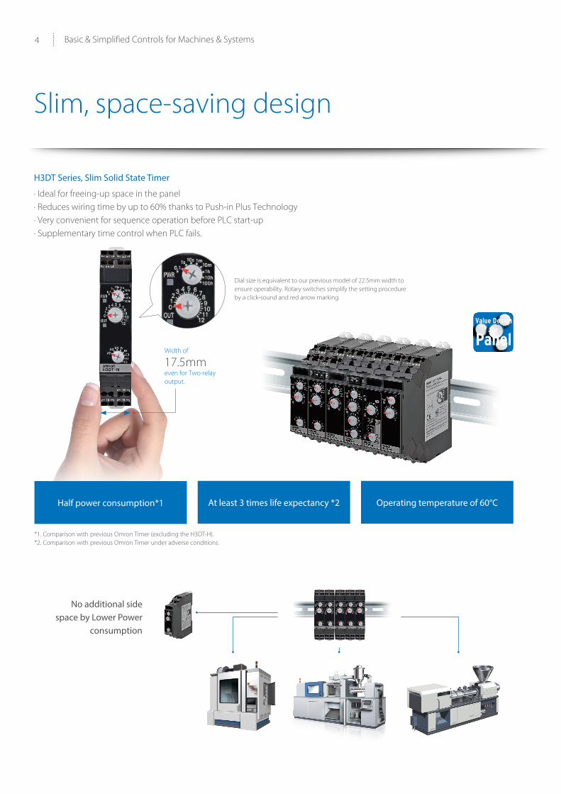
4 Basic & Simplified Controls for Machines & Systems
No additional side space by Lower Power
consumption
H3DT Series, Slim Solid State Timer
· Ideal for freeing-up space in the panel· Reduces wiring time by up to 60% thanks to Push-in Plus Technology · Very convenient for sequence operation before PLC start-up · Supplementary time control when PLC fails.
Slim, space-saving design
Dial size is equivalent to our previous model of 22.5mm width to ensure operability. Rotary switches simplify the setting procedure by a click-sound and red arrow marking
Half power consumption*1 At least 3 times life expectancy *2
*1. Comparison with previous Omron Timer (excluding the H3DT-H).*2. Comparison with previous Omron Timer under adverse conditions.
Operating temperature of 60°C
Width of
17.5mmeven for Two-relay output.

5
Faster wiring, thanks to Push-in Plus technology
*1
AccessoriesSlim Timer family
H3DK 22.5 mm Screw type, 2 x SPDT
H3DS 17.5 mm Screw type, 1 x SPDT
Y92A-D1A Front cover
Certified for safety standards globally** The Timers help to reduce the work involved in control panel design with certifications and compliance for various standards, including UL Listing.** Please check safety standard per model *1 CSA conformance evaluation by UL.
(DNV-GL is pending for certification)
Light insertion force Strong and secure connection Strong and secure connection
Earphone Jack Push-In Plus technology
8 N10 N
INSERTION FORCE
2
IEC standard (cable diameter)
Push-In Plus technology
Screw technology
20 N min. (AWG20, 0.5mm) 125 N 112 N
PULL-OUT FORCE
Earphone Jack Push-In Plus technology
8 N10 N
INSERTION FORCE
2
IEC standard (cable diameter)
Push-In Plus technology
Screw technology
20 N min. (AWG20, 0.5mm) 125 N 112 N
PULL-OUT FORCEBest-in-class (*1) power consumption
Power consumption is low, which reduces the DC power supply load for the entire control panel.
The expected service life is more than THREE times*3Reduces the work and cost involved in replacement and other maintenance.
*1. According to Omron investigation in November 2015.
*2. Comparison with previous Omron Timer (excluding the H3DT-H).
*3. Comparison with previous Omron Timer under adverse conditions.
Previous Omron Timer H3DT
60%lower power
consumption*2

6 Basic & Simplified Controls for Machines & Systems
Less wiring & maintenance
H3YN-B Series, Plug-in Timer
·Ideal for water control systems and power facilities ·Plug-in style ensures easy replacement - ideal longer life panels·Range of accessories to speed up wiring times even further.
Product features
Wider setting for Time mode & Time range by DIP Switch
Short bar solution enables common connection when several timers are installed closely.
Double wiring holes for one pole enables common connection when the timer is located on a different line.
Easy wiring by the combination with Push-in plus technology socket
PYF-14-PU Push-in Plus Accessories
Good hold & precise positioning by a jagged disk
Clip Screw Socket Screw-less Socket H3RN-B H3Y-B
Y92H-3PYF08APYF14A
PYF-08-PU-LPYF-14-PU-L
Multi-mode 1 x SPDT or 2 x SPST
On-delay Single time range DPDT
or 4PDT

7
Good visibility & accurate setting
H3CR/H5CX Series, Analog Timer & Digital Timer
• Ideal for applications such as traffic control systems or small machines which do not have a Programmable Terminal (Touch Panel)
• Good visibility & accurate setting help operators adjust setting precisely .• DIN48x48mm, size, Panel installation is possible by the mounting adapter.
Product features
H3CR Series, Analog Timer
H5CX Series, Digital Timer, bigger LED Letters & Wider Angle
Easy to know the status of output by Switchable Display color
Accessories
Easy to know the status of output
Before the setting value On status and it change the color
On Panel Mounting Adaptor
DIN rail Mount Socket
Hard protect Cover
Soft protect Cover
Waterproof packing
Y92F-30P2CF-08-EP2CF-11-E
Y92A-48B Y92A-48F1 Y92S-29
Power LED flashes when it starts the count up
The numbers on the unit change along with the setting.
Easy to see the setting status
Out LED lights when the output is on-status

16
Selection GuideSlim Timer H3DT series
Timer category Analog Timer
Multi operation Power ON Delay Twin Timer Star-Delta Timer Power OFF Delay
Operation mode ON-delayFlickerSignal ON/OFF-delaySignal OFF-delayIntervalSignal OFF-intervalOne-shotCumulative
ON-delay Flicker OFF startFlicker ON start(Independent time setting for ON time and for OFF time)
Star-Delta Power OFF Delay
Model name H3DT-L/N H3DT-A H3DT-F H3DT-G H3DT-H
Appearance
17.5×90 17.5×90 17.5×90 17.5×90 17.5×90
Mounting method
Direct Mount – – – – –
On-Panel Mount – – – – –
DIN-Rail Mount
On board Mount – – – – –
Time setting
Cover range of time
Numbers of scale change
8 8 8 2 8
Terminal structure Screwless terminal(Push-in Plus)
Screwless terminal(Push-in Plus)
Screwless terminal(Push-in Plus)
Screwless terminal(Push-in Plus)
Screwless terminal(Push-in Plus)
Power supply voltage AC/DC24~240 V AC/DC24~240 V AC/DC24~240 V AC/DC24~240 V • AC100-120 V• AC200-240 V• AC/DC24-48 V
Control output
Relay Time output 250 VAC/30 VDC 5 A
250 VAC/30 VDC 5 A
250 VAC/30 VDC 5 A
250 VAC/30 VDC 5 A
250 VAC/30 VDC 5 A
Time & Instantenious output
250 VAC/30 VDC 5 A
– – – –
Transistor – – – – –
Time accuracy
Accuracy of operating time
±1% FS max.
Setting error ±10% FS max ±0.05 s FS max
Influence of voltage ±0.5% FS max
Influence of temperature
±2% FS max
Standards CE, UL, CSA, LR, CCC, DNV-GL
1200h
300h120h60h30h24h12h10h6h3h1h30m12m10m6m5m3m2m1m30s18s12s10s6s5s3s2s1.25s1.2s1s0.6s0.5s0.3s0.2s0.1s0.05s0.04s
1200h
300h120h60h30h24h12h10h6h3h1h30m12m10m6m5m3m2m1m30s18s12s10s6s5s3s2s1.25s1.2s1s0.6s0.5s0.3s0.2s0.1s0.05s0.04s
1200h
300h120h60h30h24h12h10h6h3h1h30m12m10m6m5m3m2m1m30s18s12s10s6s5s3s2s1.25s1.2s1s0.6s0.5s0.3s0.2s0.1s0.05s0.04s
300h120h60h30h24h12h10h6h3h1h30m12m10m6m5m3m2m1m30s18s12s10s6s5s3s2s1.25s1.2s1s0.6s0.5s0.3s0.2s0.1s0.05s0.04s
300h120h60h30h24h12h10h6h3h1h30m12m10m6m5m3m2m1m30s18s12s10s6s5s3s2s1.25s1.2s1s0.6s0.5s0.3s0.2s0.1s0.05s0.04s
Timers_Selection_guide.fm Seite 16 Montag, 14. November 2016 4:44 16
8

Selection Guide
17
Dimensions
Model number legend
17.5
90
90
865H3DT-N1
H3DT-L1
100
1 3 42H3DT-@@@@
1. Type 2. Control Output *
* N-, L- and A-type models only.
3. Supply Voltage
* H-type models only.
4. Time Ranges *
* H-type models only.
Symbol Meaning
N Standard Eight-mode Timer
L Expansion Eight-mode Timer
A Power ON-delay Timer
F Twin Timer
G Star-delta Timer
H Power OFF-delay Timer
Symbol Meaning
1 SPDT
2 DPDT
Symbol Meaning
Blank 24 to 240 VAC/DC
B * 24 to 48 VAC/DC
C * 100 to 120 VAC
D * 200 to 240 VAC
Symbol Meaning
S 0.1 to 1.2 s or 1 to 12 s
L 1 to 12 s or 10 to 120 s
Timers_Selection_guide.fm Seite 17 Montag, 14. November 2016 4:44 16
9

Selection Guide
18
Plug-in socket series
Selection guide Dimensions
Timer category Analog Timer
Multi operation Multi operation
Operation mode ON-delayFlicker OFF startFlicker ON startInterval
ON-delayFlicker OFF startFlicker ON startInterval
Model name H3YN-B H3RN-B
Appearance
21.5×28 12.8×31.2
Mounting method
Direct Mount
On-Panel Mount –
DIN-Rail Mount
On board Mount – –
Time setting
Cover range of time
Numbers of scale change
4 4
Terminal structure Plug-in connection8 pins or 11 pins
Plug-in connection5 pins or 8 pins
Power supply voltage • AC100-120 V• AC200-240 V• DC100-110 V• AC24 V• DC12 V• DC24 V• DC48 V
• AC24 V• DC12 V• DC24 V
Control output
Relay Time output DPDT: 250 VAC 5 A4PDT: 250 VAC 3 A
250 VAC 5 A
Time & Instantenious output
– –
Transistor – –
Time accuracy
Accuracy of operating time
±1% FS max. (1 s range: ±1% ±10 ms max.)
Setting error ±10% FS max ±0.05 s FS max
±15% FS max ±0.05 s FS max
Influence of voltage ±2% FS max
Influence of temperature
±2% FS max
Standards CE, UL, CSA, LR, CCC CE, UL, CSA
300h120h60h30h24h12h10h6h3h1h30m12m10m6m5m3m2m1m30s18s12s10s6s5s3s2s1.25s1.2s1s0.6s0.5s0.3s0.2s0.1s0.05s0.04s
300h120h60h30h24h12h10h6h3h1h30m12m10m6m5m3m2m1m30s18s12s10s6s5s3s2s1.25s1.2s1s0.6s0.5s0.3s0.2s0.1s0.05s0.04s
H3YN-2-B/-21-B Front Mounting
H3YN-4-B/-41-B Front Mounting H3YN-4-Z-B/-41-Z-B
(63.0)
0.5
4 52.6 6.4 21.5 max.
28 max.
(63.0)
0.5
4 52.6 6.421.5 max.
28 max.
4647.26 12.8
31.2 28.8
4647.26 12.8
31.2 28.8
H3RN-1-B/H3RN-11-B Front Mounting
H3RN-2-B/H3RN-21-B Front Mounting
Timers_Selection_guide.fm Seite 18 Montag, 14. November 2016 4:44 16
10

Selection Guide
19
Model number legend
Accessories (Order separately)
Clip
Socket
Note: Cannot be used with the H3YN-_-0 (PCB terminals).
Model number legend
List of models
Accessories (Order separately)
Socket
27.6
30.828.1
35.5
27.25
27.6
36.345
3.9
52.1
(4.2)
(4.2)
90 max.
31 max. 4536.3
27.6
3.9
35.5
27.25
27.628.1
52.1
90 max.
(4.2)
(4.2)
31 max.
30.8PYF-08-PU-L PYF-14-PU-L
52.4
4536.3
27.6
27.25
35.5
28.127.6
52.1
3.9
56.5 max. 56.5 max.
15.5 max.
90 max.
(3)
(3)
Release lever
P2RF-05-PU P2RF-08-PU
27.628.1
4536.3
27.6
35.5
27.25
52.1
52.4
3.9
15.5 max.
(3)
(3)
90 max.Release lever
H3Y-_-B/H3YN-_-B Series for PYF-_-PU-L SocketY92H-3 (Set of two clips)
5 max.
53
4.51.24.5
PYF-08-PU-L (PYF-14-PU-L *2)
PYF-08-PU-L (PYF-14-PU-L)
88.692 7881.4 *
82.8 *
P2RF-_-E
56.3
H3RN-_-BH3Y(N)-BSeries
P2RF-_-PU
Note: There are no restrictions to the mounting direction.
* These values apply when the PFP-_N is used.Add 9 mm if you use the PFP-_N2.
Name/specification Model
Clip For PYF-@-PU-L Y92H-3
Timer Square Sockets
Contact Model Pin Connection Terminal Model Terminal Type
DPDT H3YN-2_-B 8-pin Front Connecting
DIN track mounting
PYF-08-PU-L Push-In Plus Terminal Block4PDT H3YN-4_-B 14-pin PYF-14-PU-L
1 3 42H3YN-@@@-@
Supply voltageEx: H3YN-2 100 to 120 VAC
(1) Output (2) Time range (3) Contact typeSymbol Meaning Symbol Meaning Symbol Meaning
2 DPDT None Short-time range None Single contact
4 4PDT 0 Long-time range Z Twin contacts
(4) Body color and Terminal arrangementSymbol Meaning
None Beige with output terminals on top and power supply terminals on bottom
B Black with power supply terminals on top and output terminals on bottom
Supply voltage
Time-limit contact
Short-time range model(0.1 s to 10 min)
Long-time range model(0.1 min to 10 h)
24 VAC;12, 24 VDC
SPDT H3RN-1-B H3RN-11-B
DPST-NO H3RN-2-B H3RN-21-B
Timer Track mounting/Front connecting socket
H3RN-1-B/-11-B P2RF-05-PU
H3RN-2-B/-21-B P2RF-08-PU
1 2H3RN-@@-B
(1) Output (2) Time rangeSymbol Meaning Symbol Meaning
1 SPDT None Short-time range (0.1 s to 10 min)
2 DPST-NO 1 Long-time range (0.1 min to 10 hrs)
Note: Specify both the model number and supply voltage when ordering.Example: H3RN-1-B 24 VAC
Supply voltage
Timers_Selection_guide.fm Seite 19 Montag, 14. November 2016 4:44 16
11

Selection Guide
20
On Panel series
Dimensions
Timer category Analog Timer
Multi operation Twin Timer Star-Delta Timer Power OFF Delay
Operation mode ON-delayFlickerSignal ON/OFF-delaySignal OFF-delayIntervalOne-shot
Flicker OFF startFlicker ON start(Independent time setting for ON time and for OFF time)
Star-Delta Power O?? Delay
Model name H3CR-A H3CR-F H3CR-G H3CR-H
Appearance
DIN 48×48 DIN 48×48 DIN 48×48 DIN 48×48
Mounting method
Direct Mount
On-Panel Mount
DIN-Rail Mount
On board Mount – – – –
Time setting
Cover range of time
Numbers of scale change
20 20 4 4
Terminal structure Plug-in connection8 pins or 11 pins
Plug-in connection8 pins or 11 pins
Plug-in connection8 pins
Plug-in connection8 pins or 11 pins
Power supply voltage • AC100~240 VAC/100~125 VDC
• 24~48 VAC/12~48 VDC
• AC100~240 VAC/100~125 VDC
• 24~48 VAC/12~48 VDC
• 100/110/120 VAC• 200/220/240 VAC• 24 VAC/DC• 48 VDC• 100-125 VDC
• 100/110/120 VAC• 200/220/240 VAC
Control output
Relay Time output 250 VAC/30 VDC 5 A125 VDC 0.15 A
250 VAC/30 VDC 5 A
250 VAC/30 VDC 5 A
250 VAC/30 VDC 5 A
Time & Instantenious output
250 VAC/30 VDC 5 A125 VDC 0.15 A
– 250 VAC/30 VDC 5 A
–
Transistor 30 VDC 100 mA
– – –
Time accuracy
Accuracy of operating time
±0.2% FS max
Setting error ±0.5% FS max ±0.05 s max
Influence of voltage ±0.2% FS max
Influence of temperature
±1% FS max
Standards CE, UL, CSA, LR, CCC, NK
300h120h60h30h24h12h10h6h3h1h30m12m10m6m5m3m2m1m30s18s12s10s6s5s3s2s1.25s1.2s1s0.6s0.5s0.3s0.2s0.1s0.05s0.04s
300h120h60h30h24h12h10h6h3h1h30m12m10m6m5m3m2m1m30s18s12s10s6s5s3s2s1.25s1.2s1s0.6s0.5s0.3s0.2s0.1s0.05s0.04s
300h120h60h30h24h12h10h6h3h1h30m12m10m6m5m3m2m1m30s18s12s10s6s5s3s2s1.25s1.2s1s0.6s0.5s0.3s0.2s0.1s0.05s0.04s
300h120h60h30h24h12h10h6h3h1h30m12m10m6m5m3m2m1m30s18s12s10s6s5s3s2s1.25s1.2s1s0.6s0.5s0.3s0.2s0.1s0.05s0.04s
48
48
66.652.3
15
6
44.8 × 44.8
0.7
11 pins
39 dia.
66.6
44.8 × 44.8
52.3
0.7
6
17.4
5.7
37 din.14 din.
11 pins
H3CR-A/F H3CR-F H3CR-G/HH3CR-A
44.8 5 44.8
(78)
63.7
79.4
0.713.6
6
15
39 dia.
48
48
Timers_Selection_guide.fm Seite 20 Montag, 14. November 2016 4:44 16
Selection Guide
21
Model number legend
100.8* 98.5
2.3*
89.9* 87.6
2.3*P2CF-11P2CF-11-E
P2CF-08P2CF-08-E
8015 15
7581.5 81.5
Y92F-30P3GA-11
Y92F-30P3G-08
(When Y92A-48G mounted)
(When Y92A-48G mounted)
103.2* 100.9
2.3*
92.3* 90.0
2.3*
H3CR-F H3CR-FN
P2CF-11 P2CF-11-E
H3CR-F8 H3CR-F8N
P2CF-08 P2CF-08-E
8017.4 17.4
75
81.5 81.5
Y92F-30P3GA-11
Y92F-30P3G-08
H3CR-F H3CR-FN
+Adapter
H3CR-F8 H3CR-F8N
+Adapter
(When Y92A-48G mounted)
(When Y92A-48G mounted)
H3CR-F(8 pin)
H3CR-A(8 pin)
H3CR-F(11 pin)
H3CR-G/H(8 pin)
H3CR-H(11 pin)
H3CR-A(11 pin)
DINMount
ON-PanelMount
101.3* 99
2.3*P2CF-08 P2CF-08-E
1586.492.9
Y92F-30P3G-08
(When Y92A-48G mounted)
112.2* 109.9
2.3*P2CF-11 P2CF-11-E
15 91.492.9
Y92F-30P3GA-11
(When Y92A-48G mounted)
Y92F-30
45+0.6-0
(N)
45+0.6-0
Panel Cutout(Conforms to DIN 43700)
0.5 R max.
Finger Safe Terminal CoverConforming to VDE0106/P100
Y92A-48G
(Attachment for P3G-08/P3GA-11 Socket)
45
45 4.9 17
45
45
25.6
4.516.3
6.2
27 dia. P3GA-1127 dia.
P3G-08
7.83 4.5
35.4
4
70 max.
50 max.20.3 max.
P2CF-08Eight, M3.5 × 7.5 sems
Two, 4.5 dia. holes
40±0.2
7.8
4
35.4
20.319
3
1.3
5 4.5
P2CF-08-E (Finger Safe Terminal Type)Conforming to VDE0106/P100
50 max.
70 max.
21.5 max.
Two, 4.5 dia. holes
Eight,M3.5 × 7.5 sems
1 3 4 52H3CR-A@@@-@@
1 3 4 52H3CR-F@@-@@
1. Number of pinsNone 11-pin models8 8-pin models
2. Input type for 11-pin modelsNone Relay output (DPDT)S Transistor output (NPN/PNP uni-
versal use)E Relay output (SPDT) with instanta-
neous relay output (SPDT)
3. OutputNone Relay output (DPDT)S Transistor output (NPN/PNP
universal use)E Relay output (SPDT) with
instantaneous relay output (SPDT)
4. Suffix301 Double time scale (range) models
(0.1 s to 600 h)
5. Supply Voltage100-240AC/100-125DC Beige with out-
put terminals on top and power supply terminals on bottom
24-48AC/12-48DC 24 to 48 VAC/12 to 48 VDC
24-48AC/DC 24 to 48 VAC/VDC (Only for H3CR-A8E)
1. ClassificationG Star-delta timer
2. Configuration8 8-pin socket
3. OutputsNone Star-delta operation contactE Star-delta operation contact and
instantaneous contact
4. DimensionsL Long-body model
5. Supply Voltage100-120AC 100 to 120 VAC200-240AC 200 to 240 VAC
1 3 4 52H3CR-G8@L@
1. ClassificationF Twin timers
2. ConfigurationNone 11-pin socket8 8-pin socket
3. Twin timer modeNone Flicker OFF startN Flicker ON start
4. Time rangeNone 0.05 s to 300 h models
5. Supply Voltage100-240AC/100-125DC
100 to 240 VAC/100 to 125 VDC24-48AC/12-48DC
24 to 48 VAC/12 to 48 VDC
1 3 4 5 62H3CR-H@@L@@
1. ClassificationH Power OFF-delay timer
2. ConfigurationNone 11-pin socket8 8-pin socket
3. InputNone Without reset inputR With reset input
4. DimensionsL Long-body model
5. Supply Voltage100-120AC 100 to 120 VAC200-240AC 200 to 240 VAC24AC/DC 24VAC/DC48DC 48 VDC100-125DC 100 to 125 VDC
6. Time RangeS 0.05 to 12 sM 0.05 to 12 min
Timers_Selection_guide.fm Seite 21 Montag, 14. November 2016 4:44 16
12

Selection Guide
21
Model number legend
100.8* 98.5
2.3*
89.9* 87.6
2.3*P2CF-11P2CF-11-E
P2CF-08P2CF-08-E
8015 15
7581.5 81.5
Y92F-30P3GA-11
Y92F-30P3G-08
(When Y92A-48G mounted)
(When Y92A-48G mounted)
103.2* 100.9
2.3*
92.3* 90.0
2.3*
H3CR-F H3CR-FN
P2CF-11 P2CF-11-E
H3CR-F8 H3CR-F8N
P2CF-08 P2CF-08-E
8017.4 17.4
75
81.5 81.5
Y92F-30P3GA-11
Y92F-30P3G-08
H3CR-F H3CR-FN
+Adapter
H3CR-F8 H3CR-F8N
+Adapter
(When Y92A-48G mounted)
(When Y92A-48G mounted)
H3CR-F(8 pin)
H3CR-A(8 pin)
H3CR-F(11 pin)
H3CR-G/H(8 pin)
H3CR-H(11 pin)
H3CR-A(11 pin)
DINMount
ON-PanelMount
101.3* 99
2.3*P2CF-08 P2CF-08-E
1586.492.9
Y92F-30P3G-08
(When Y92A-48G mounted)
112.2* 109.9
2.3*P2CF-11 P2CF-11-E
15 91.492.9
Y92F-30P3GA-11
(When Y92A-48G mounted)
Y92F-30
45+0.6-0
(N)
45+0.6-0
Panel Cutout(Conforms to DIN 43700)
0.5 R max.
Finger Safe Terminal CoverConforming to VDE0106/P100
Y92A-48G
(Attachment for P3G-08/P3GA-11 Socket)
45
45 4.9 17
45
45
25.6
4.516.3
6.2
27 dia. P3GA-1127 dia.
P3G-08
7.83 4.5
35.4
4
70 max.
50 max.20.3 max.
P2CF-08Eight, M3.5 × 7.5 sems
Two, 4.5 dia. holes
40±0.2
7.8
4
35.4
20.319
3
1.3
5 4.5
P2CF-08-E (Finger Safe Terminal Type)Conforming to VDE0106/P100
50 max.
70 max.
21.5 max.
Two, 4.5 dia. holes
Eight,M3.5 × 7.5 sems
1 3 4 52H3CR-A@@@-@@
1 3 4 52H3CR-F@@-@@
1. Number of pinsNone 11-pin models8 8-pin models
2. Input type for 11-pin modelsNone Relay output (DPDT)S Transistor output (NPN/PNP uni-
versal use)E Relay output (SPDT) with instanta-
neous relay output (SPDT)
3. OutputNone Relay output (DPDT)S Transistor output (NPN/PNP
universal use)E Relay output (SPDT) with
instantaneous relay output (SPDT)
4. Suffix301 Double time scale (range) models
(0.1 s to 600 h)
5. Supply Voltage100-240AC/100-125DC Beige with out-
put terminals on top and power supply terminals on bottom
24-48AC/12-48DC 24 to 48 VAC/12 to 48 VDC
24-48AC/DC 24 to 48 VAC/VDC (Only for H3CR-A8E)
1. ClassificationG Star-delta timer
2. Configuration8 8-pin socket
3. OutputsNone Star-delta operation contactE Star-delta operation contact and
instantaneous contact
4. DimensionsL Long-body model
5. Supply Voltage100-120AC 100 to 120 VAC200-240AC 200 to 240 VAC
1 3 4 52H3CR-G8@L@
1. ClassificationF Twin timers
2. ConfigurationNone 11-pin socket8 8-pin socket
3. Twin timer modeNone Flicker OFF startN Flicker ON start
4. Time rangeNone 0.05 s to 300 h models
5. Supply Voltage100-240AC/100-125DC
100 to 240 VAC/100 to 125 VDC24-48AC/12-48DC
24 to 48 VAC/12 to 48 VDC
1 3 4 5 62H3CR-H@@L@@
1. ClassificationH Power OFF-delay timer
2. ConfigurationNone 11-pin socket8 8-pin socket
3. InputNone Without reset inputR With reset input
4. DimensionsL Long-body model
5. Supply Voltage100-120AC 100 to 120 VAC200-240AC 200 to 240 VAC24AC/DC 24VAC/DC48DC 48 VDC100-125DC 100 to 125 VDC
6. Time RangeS 0.05 to 12 sM 0.05 to 12 min
Timers_Selection_guide.fm Seite 21 Montag, 14. November 2016 4:44 16
13

Selection Guide
22
On Panel series
Model number legendTimer Category
Digital Timer
Multi operation Twin Timer
Operation mode Signal ON Delay Power ON Delay Repeat cycle 1Signal OFF DelayIntervalCumulativeON/OFF-duty-adjust-able flickerStopwatchTwin Timer Flicker
Flicker OFF startFlicker ON start(Independent time setting for ON time and for OFF time)
Model name H5CX H5CZ
Appearance
DIN 48×48 DIN 48×48
Mounting method
Direct Mount
On-Panel Mount
DIN-Rail Mount
On board Mount – –
Time setting
Cover range of time
Numbers of scale change
4 digits: 106 digits: 4
4 digits: 10
Terminal structure Plug-in connection8 pins or 11 pins
Plug-in connection8 pins
Power supply voltage • AC100-240 V,• AC24/DC12-24 V
Display Type LED LCD
Color of letter Green, Red, Orange Black
Digits 4 digits or 6 digits 4 digits
Waterproof IP66 with Y92S-29
IP66 with Y92S-29
Control output
Relay Time output 250 VAC/30 VDC 5 A125 VDC 0.15 A
250 VAC/30 VDC 5 A
Time & Instantenious output
250 VAC/30 VDC 5 A125 VDC 0.15 A
250 VAC/30 VDC 5 A
Transistor 30 VDC 100 mA
–
Time accuracy
Accuracy of operating time
• Power Start±0.01% ±0.05 s max
• Signal Start±0.005% ±0.03 s max
• Signal Start by Transistor±0.005% ±3 ms max
• Power Start±0.01% ±0.05 s max
• Signal Start ±0.005% ±0.03 s max
Setting error
Influence of voltage
Influence of temperature
Standards CE, UL, CCC CE, UL, CCC
99999.9h
10000h9999h9990h
100h
1h40m1h
16m40s6m
1m40s1m10s
1s0.1s
0.01s0.001s
99999.9h
10000h9999h9990h
99h59m
1h40m1h
16m40s6m
1m40s1m10s
1s0.1s
0.01s0.001s
1 3 4 52H5CX-@@@@@-N
1 32H5CZ-L@@@
1. Type classifierA Standard typeB 6-digit typeL Economy type
2. External connectionsNone Screw terminals8 8-pin socket11 11-pin socket
3. SettingsNone One stageW Two stages
4. Output typeNone Contact output (time-limit SPDT)E Contact output (time-limit SPDT +
instantaneous SPDT) *1
S Transistor output
5. Supply voltageNone 100 to 240 VAC 50/60 Hz D 12 to 24 VDC/24 VAC 50/60 Hz*2
*1 Can be used as a time-limit DPDT output.*2 The H5CX-BWSD-N is available only for 12
to 24 VDC.
1. External connections8 8-pin socket
2. Output typeNone Contact output (time-limit SPDT)E Contact output (time-limit SPDT +
instantaneous SPDT)*1
3. Supply voltageNone 100 to 240 VAC 50/60 Hz D 12 to 24 VDC/24 VAC 50/60 Hz
*1 Can be used as a time-limit DPDT output.
Timers_Selection_guide.fm Seite 22 Montag, 14. November 2016 4:44 16
14

Selection Guide
23
Dimensions
786
44.8×44.8
48×48
58
48 76.57.5
(51)
Y92S-29 (provided) Waterproof Packing
Y92F-30 (provided) Flush Mounting Adapter
Panel
H5CX-A-N/-AS-N (Provided with Adapter and Waterproof Packing)H5CX-A-N/-AS-N (Flush mounting models)
H5CX-AD-N/-ASD-N (Provided with Adapter and Waterproof Packing)H5CX-AD-N/-ASD-N (Flush mounting models)
H5CX-L8@-N (Adapter and Waterproof Packing ordered separately)H5CX-L8@-N (Flush mounting/Surface mounting models)
H5CX-A11@-N (Adapter and Waterproof Packing ordered separately)H5CX-A11@-N (Flush mounting/Surface mounting models)
63.714.4
6
44.8×44.8
48×48
58
48 89.97.5
(51)
Y92S-29 (order separately) Waterproof Packing
Y92F-30 (order separately) Flush Mounting Adapter
P3GA-11 (order separately) Back-connecting Socket
Panel
58
48 57.57.5
(51)
Y92S-29 (provided) Waterproof Packing
Y92F-30 (provided) Flush Mounting Adapter
Panel
596
44.8×44.8
48×48
58
48 84.87.5
(51)
Y92F-30 (order separately) Flush Mounting Adapter P3G-08 (order
separately) Back-connecting Socket
PanelY92S-29 (order separately) Waterproof Packing
63.714.2
6
44.8×44.8
48×48
103.2 100.9
H5CX-A11@-N
P2CF-11(-E) (order separately)Front Connecting Socket
* H5CX-L8@-N
P2CF-08(-E) (order separately) Front Connecting Socket
92.3 90*
Dimensions with Front Connecting Socket
1 27 8
4 36 5
P2CF-08-E
10A250VACRESISTIVE
4
70 max.
Two, 4.5-dia. holes
Eight, M3.5 x 7.5 set screws7.8
21.5 max.
20.3
19
4.5
35.41.3
3
5
50 max.
40±0.2
10 11 1 2
78 6 5
3
4
9
P2CF-11-E
10A250VACRESISTIVE
4
70 max.
50 max.
40±0.2
Two, 4.5-dia. holes
Eleven, M3.5 x 7.5 set screws7.8
31.2 max.
30
4.5
35.41.2
3
5
P2CF-08-E (Finger Safe terminal)Conforming to VDE0106/P100
P2CF-11-E (Finger Safe terminal)Conforming to VDE0106/P100
Timers_Selection_guide.fm Seite 23 Montag, 14. November 2016 4:44 16
15

Although we strive for perfection, Omron Europe BV and/or its subsidiary and affiliated companies do not warrant or make any representations regarding the correctness or completeness of the information described in this document. We reserve the right to make any changes at any time without prior notice.EU_01_timer_BR
Would you like to know more?
OMRON EUROPE
+31 (0) 23 568 13 00
industrial.omron.eu
Austria Tel: +43 (0) 2236 377 800 industrial.omron.at
Belgium Tel: +32 (0) 2 466 24 80 industrial.omron.be
Czech Republic Tel: +420 234 602 602 industrial.omron.cz
Denmark Tel: +45 43 44 00 11 industrial.omron.dk
Finland Tel: +358 (0) 207 464 200industrial.omron.fi
France Tel: +33 (0) 1 56 63 70 00industrial.omron.fr
Germany Tel: +49 (0) 2173 680 00 industrial.omron.de
Hungary Tel: +36 1 399 30 50 industrial.omron.hu
Italy Tel: +39 02 326 81 industrial.omron.it
Netherlands Tel: +31 (0) 23 568 11 00 industrial.omron.nl
Norway Tel: +47 22 65 75 00 industrial.omron.no
Poland Tel: +48 22 458 66 66 industrial.omron.pl
Portugal Tel: +351 21 942 94 00 industrial.omron.pt
Russia Tel: +7 495 648 94 50 industrial.omron.ru
South AfricaTel: +27 (0)11 579 2600 industrial.omron.co.za
Spain Tel: +34 902 100 221 industrial.omron.es
Sweden Tel: +46 (0) 8 632 35 00 industrial.omron.se
Switzerland Tel: +41 (0) 41 748 13 13 industrial.omron.ch
Turkey Tel: +90 (216) 556 51 30 industrial.omron.com.tr
United Kingdom Tel: +44 (0) 1908 258 258 industrial.omron.co.uk
More Omron representatives industrial.omron.eu