basic structure of computers by aniket bhute
TRANSCRIPT
CHAPTER 1. BASIC STRUCTURE OF COMPUTERS
By Aniket Bhute
G.H.RAISONI COLLEGE OF ENGINEERING
(An Autonomous Institute Under UGC act 1956 & affiliated to R.T.M. Nagpur University)
FUNCTIONAL UNITS
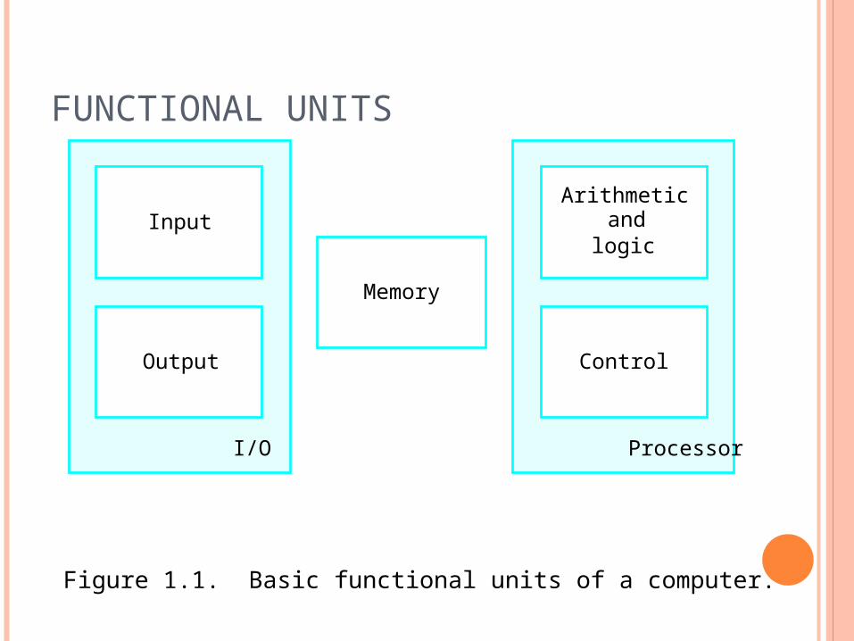
FUNCTIONAL UNITS
Figure 1.1. Basic functional units of a computer.
I/O Processor
Output
Memory
Input andArithmetic
logic
Control
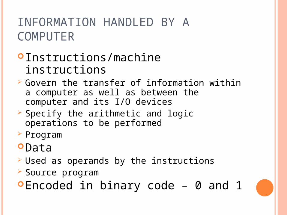
INFORMATION HANDLED BY A COMPUTERInstructions/machine instructions Govern the transfer of information within a
computer as well as between the computer and its I/O devices
Specify the arithmetic and logic operations to be performed
ProgramData Used as operands by the instructions Source programEncoded in binary code – 0 and 1
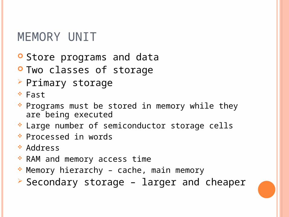
MEMORY UNIT Store programs and data Two classes of storage Primary storage Fast Programs must be stored in memory while they are
being executed Large number of semiconductor storage cells Processed in words Address RAM and memory access time Memory hierarchy – cache, main memory Secondary storage – larger and cheaper
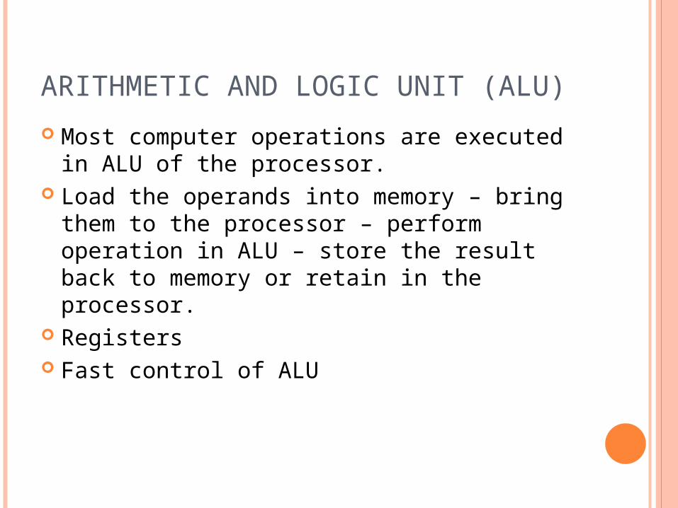
ARITHMETIC AND LOGIC UNIT (ALU) Most computer operations are executed in
ALU of the processor. Load the operands into memory – bring them
to the processor – perform operation in ALU – store the result back to memory or retain in the processor.
Registers Fast control of ALU
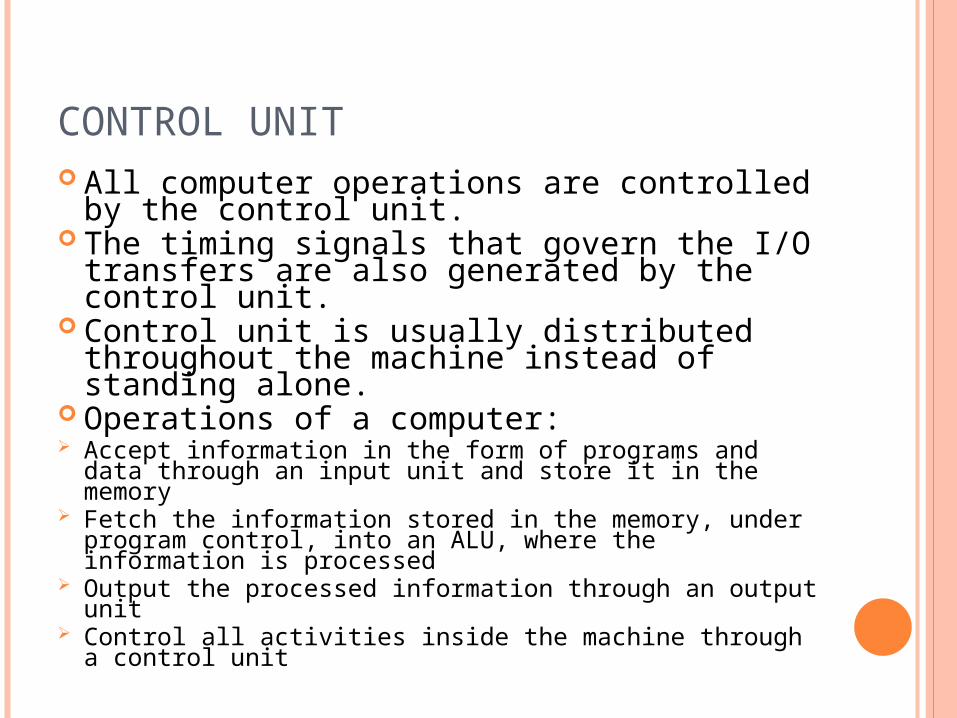
CONTROL UNIT All computer operations are controlled by the control unit. The timing signals that govern the I/O transfers are also generated by the control unit. Control unit is usually distributed throughout the machine instead of standing alone. Operations of a computer: Accept information in the form of programs and data through an input unit and store it in the memory Fetch the information stored in the memory, under program control, into an ALU, where the information is processed Output the processed information through an output unit Control all activities inside the machine through a control unit
THE PROCESSOR : DATA PATH AND CONTROL
PCRegister
Bank
Data Memory
Address
Instructions Address
Data
Instruction Memory
A L U
Data
Register #
Register #
Register #
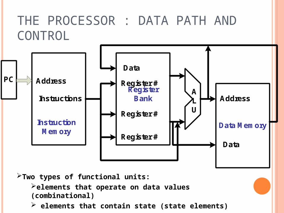
Two types of functional units:elements that operate on data values (combinational) elements that contain state (state elements)
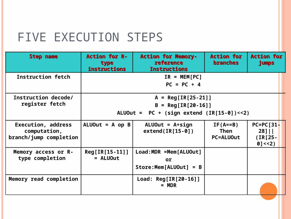
FIVE EXECUTION STEPSStep nameStep name Action for R-type Action for R-type
instructionsinstructionsAction for Memory-Action for Memory-
reference Instructionsreference InstructionsAction for Action for branchesbranches
Action for Action for jumpsjumps
Instruction fetch IR = MEM[PC]PC = PC + 4
Instruction decode/ register fetch
A = Reg[IR[25-21]]B = Reg[IR[20-16]]
ALUOut = PC + (sign extend (IR[15-0])<<2)
Execution, address computation, branch/jump
completion
ALUOut = A op B ALUOut = A+sign extend(IR[15-0])
IF(A==B) Then PC=ALUOut
PC=PC[31-28]||(IR[25-
0]<<2)
Memory access or R-type completion
Reg[IR[15-11]] = ALUOut
Load:MDR =Mem[ALUOut]or
Store:Mem[ALUOut] = B
Memory read completion Load: Reg[IR[20-16]] = MDR
BASIC OPERATIONAL CONCEPTS
REVIEW Activity in a computer is governed by
instructions. To perform a task, an appropriate
program consisting of a list of instructions is stored in the memory.
Individual instructions are brought from the memory into the processor, which executes the specified operations.
Data to be used as operands are also stored in the memory.
A TYPICAL INSTRUCTION Add LOCA, R0 Add the operand at memory location LOCA
to the operand in a register R0 in the processor.
Place the sum into register R0. The original contents of LOCA are
preserved. The original contents of R0 is overwritten. Instruction is fetched from the memory into
the processor – the operand at LOCA is fetched and added to the contents of R0 – the resulting sum is stored in register R0.
SEPARATE MEMORY ACCESS AND ALU OPERATION Load LOCA, R1 Add R1, R0 Whose contents will be overwritten?
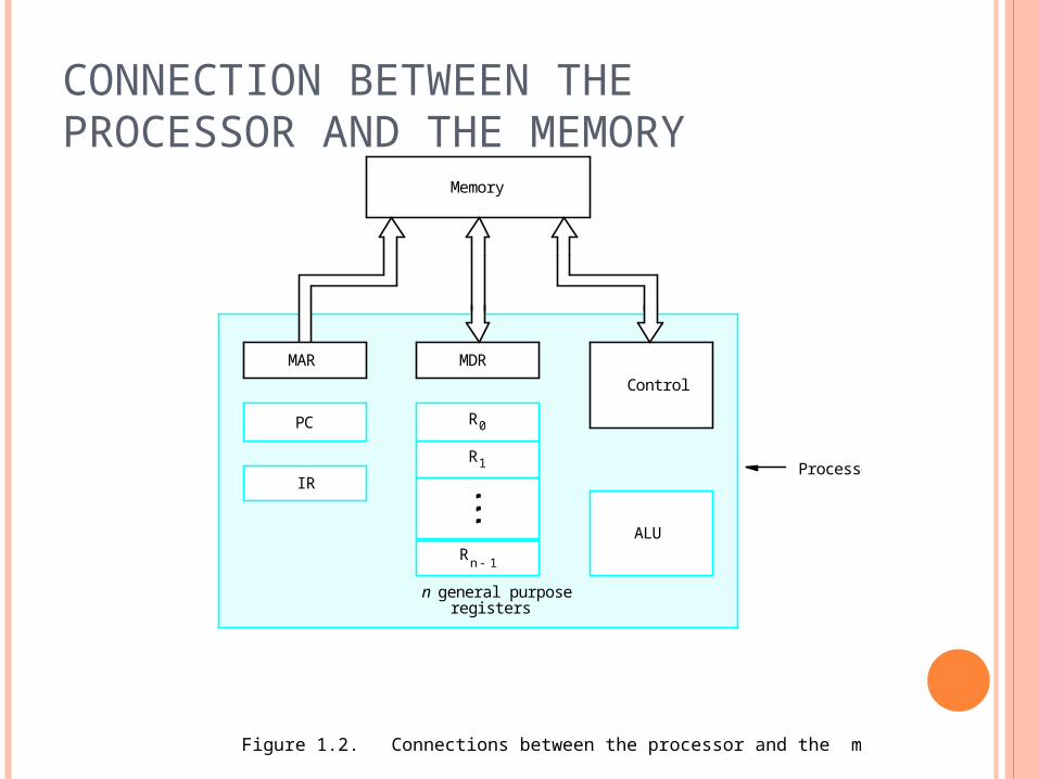
CONNECTION BETWEEN THE PROCESSOR AND THE MEMORY
Figure 1.2. Connections between the processor and the memory.
Processor
Memory
PC
IR
MDRControl
ALURn 1-
R1
R0
MAR
n general purposeregisters
REGISTERS Instruction register (IR) Program counter (PC) General-purpose register (R0 – Rn-1) Memory address register (MAR) Memory data register (MDR)
TYPICAL OPERATING STEPS Programs reside in the memory through input
devices PC is set to point to the first instruction The contents of PC are transferred to MAR A Read signal is sent to the memory The first instruction is read out and loaded
into MDR The contents of MDR are transferred to IR Decode and execute the instruction
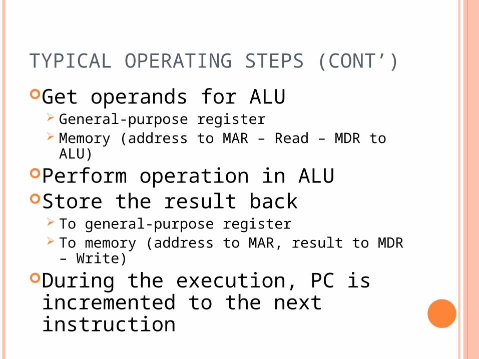
TYPICAL OPERATING STEPS (CONT’)Get operands for ALU
General-purpose register Memory (address to MAR – Read – MDR to ALU)
Perform operation in ALUStore the result back
To general-purpose register To memory (address to MAR, result to MDR –
Write)During the execution, PC is incremented to the next instruction
INTERRUPT Normal execution of programs may be
preempted if some device requires urgent servicing.
The normal execution of the current program must be interrupted – the device raises an interrupt signal.
Interrupt-service routine Current system information backup and
restore (PC, general-purpose registers, control information, specific information)
BUS STRUCTURES There are many ways to connect different
parts inside a computer together. A group of lines that serves as a connecting
path for several devices is called a bus. Address/data/control
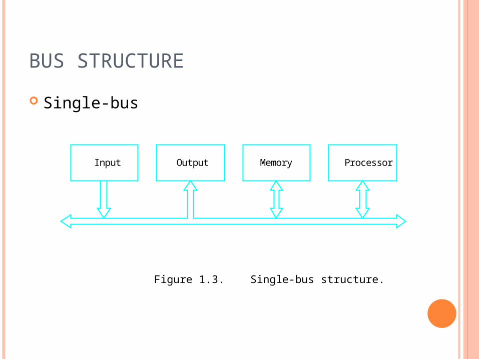
BUS STRUCTURE Single-bus
Figure 1.3. Single-bus structure.
MemoryInput Output Processor
SPEED ISSUE Different devices have different
transfer/operate speed. If the speed of bus is bounded by the slowest
device connected to it, the efficiency will be very low.
How to solve this? A common approach – use buffers.

PERFORMANCE
PERFORMANCE The most important measure of a computer
is how quickly it can execute programs. Three factors affect performance: Hardware design Instruction set Compiler
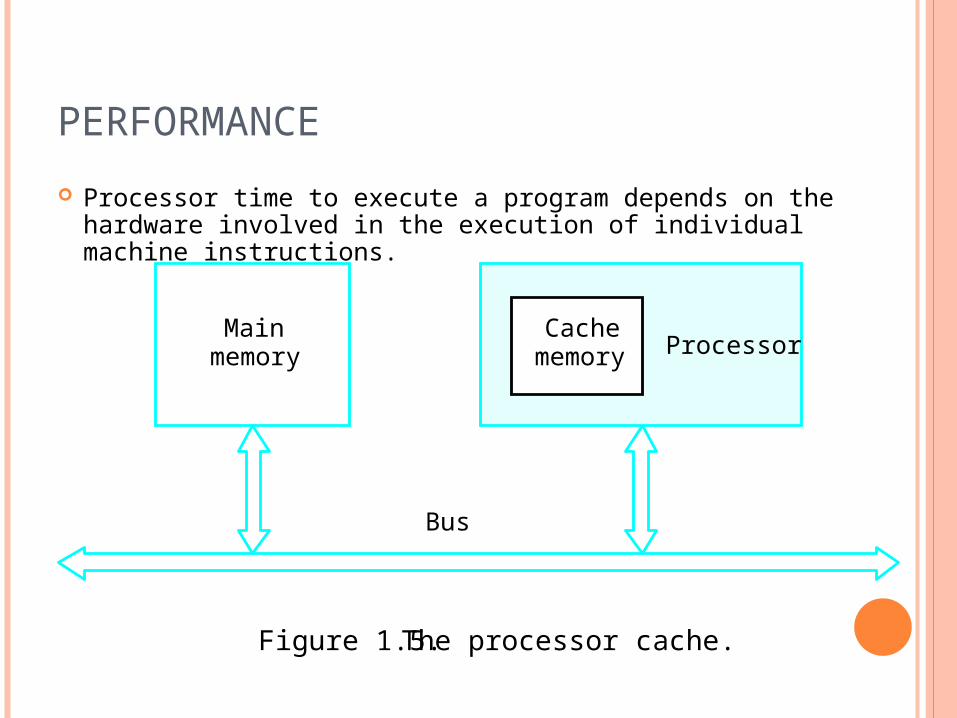
PERFORMANCE Processor time to execute a program depends on the hardware
involved in the execution of individual machine instructions.
Mainmemory Processor
Bus
Cachememory
Figure 1.5. The processor cache.
PERFORMANCE The processor and a relatively small cache
memory can be fabricated on a single integrated circuit chip.
Speed Cost Memory management
PROCESSOR CLOCK Clock, clock cycle, and clock rate The execution of each instruction is divided
into several steps, each of which completes in one clock cycle.
Hertz – cycles per second
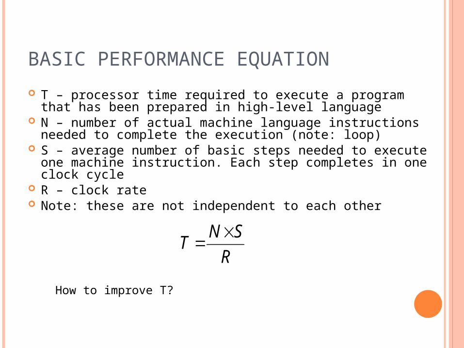
BASIC PERFORMANCE EQUATION T – processor time required to execute a program that has
been prepared in high-level language N – number of actual machine language instructions needed
to complete the execution (note: loop) S – average number of basic steps needed to execute one
machine instruction. Each step completes in one clock cycle R – clock rate Note: these are not independent to each other
RSNT
How to improve T?
PIPELINE AND SUPERSCALAR OPERATION Instructions are not necessarily executed
one after another. The value of S doesn’t have to be the
number of clock cycles to execute one instruction.
Pipelining – overlapping the execution of successive instructions.
Add R1, R2, R3 Superscalar operation – multiple
instruction pipelines are implemented in the processor.
Goal – reduce S (could become <1!)
CLOCK RATE Increase clock rate Improve the integrated-circuit (IC)
technology to make the circuits faster Reduce the amount of processing done in
one basic step (however, this may increase the number of basic steps needed)
Increases in R that are entirely caused by improvements in IC technology affect all aspects of the processor’s operation equally except the time to access the main memory.
CISC AND RISC Tradeoff between N and S A key consideration is the use of pipelining S is close to 1 even though the number of
basic steps per instruction may be considerably larger
It is much easier to implement efficient pipelining in processor with simple instruction sets
Reduced Instruction Set Computers (RISC) Complex Instruction Set Computers (CISC)
COMPILER A compiler translates a high-level
language program into a sequence of machine instructions.
To reduce N, we need a suitable machine instruction set and a compiler that makes good use of it.
Goal – reduce N×S A compiler may not be designed for a
specific processor; however, a high-quality compiler is usually designed for, and with, a specific processor.
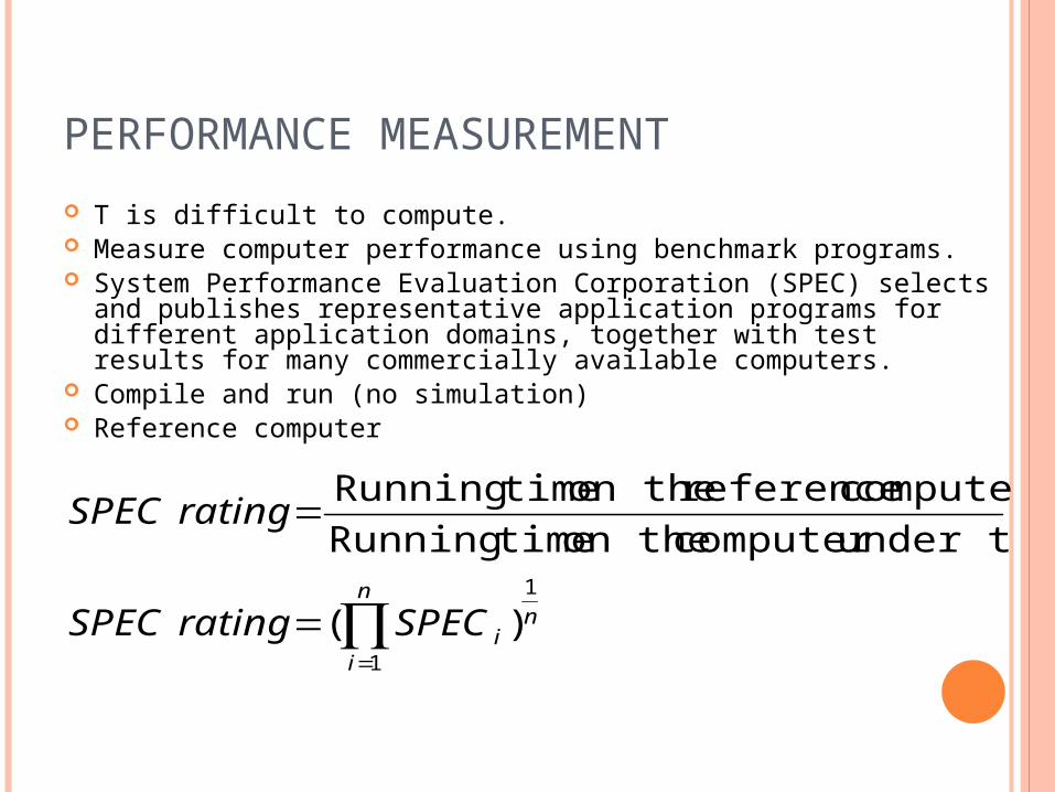
PERFORMANCE MEASUREMENT T is difficult to compute. Measure computer performance using benchmark programs. System Performance Evaluation Corporation (SPEC) selects and
publishes representative application programs for different application domains, together with test results for many commercially available computers.
Compile and run (no simulation) Reference computer
n
i
niSPECratingSPEC
ratingSPEC
1
1
)(
under testcomputer on the timeRunningcomputer reference on the timeRunning
MULTIPROCESSORS AND MULTICOMPUTERS Multiprocessor computer Execute a number of different application tasks in
parallel Execute subtasks of a single large task in parallel All processors have access to all of the memory –
shared-memory multiprocessor Cost – processors, memory units, complex
interconnection networks Multicomputers Each computer only have access to its own memory Exchange message via a communication network –
message-passing multicomputers

CHAPTER 2. MACHINE
INSTRUCTIONS AND PROGRAMS
OBJECTIVES Machine instructions and program execution,
including branching and subroutine call and return operations.
Number representation and addition/subtraction in the 2’s-complement system.
Addressing methods for accessing register and memory operands.
Assembly language for representing machine instructions, data, and programs.
Program-controlled Input/Output operations.
NUMBER, ARITHMETIC
OPERATIONS, AND CHARACTERS
SIGNED INTEGER 3 major representations: Sign and magnitude One’s complement Two’s complement Assumptions: 4-bit machine word 16 different values can be represented Roughly half are positive, half are
negative
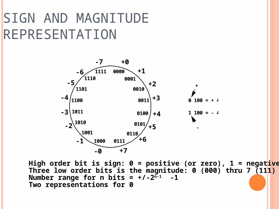
SIGN AND MAGNITUDE REPRESENTATION
0000
0111
0011
1011
11111110
1101
1100
1010
10011000
0110
0101
0100
0010
0001
+0+1
+2
+3
+4
+5
+6+7-0
-1
-2
-3
-4
-5-6
-7
0 100 = + 4 1 100 = - 4
+
-
High order bit is sign: 0 = positive (or zero), 1 = negativeThree low order bits is the magnitude: 0 (000) thru 7 (111)Number range for n bits = +/-2n-1 -1Two representations for 0
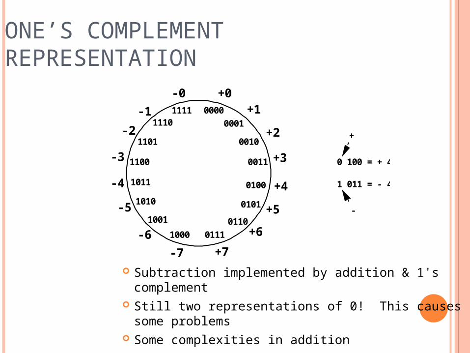
ONE’S COMPLEMENT REPRESENTATION
Subtraction implemented by addition & 1's complement
Still two representations of 0! This causes some problems
Some complexities in addition
0000
0111
0011
1011
11111110
1101
1100
1010
10011000
0110
0101
0100
0010
0001
+0+1
+2
+3
+4
+5
+6+7-7
-6
-5
-4
-3
-2-1
-0
0 100 = + 4 1 011 = - 4
+
-
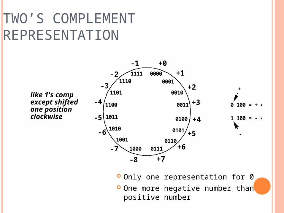
TWO’S COMPLEMENT REPRESENTATION
Only one representation for 0 One more negative number than positive
number
0000
0111
0011
1011
11111110
1101
1100
1010
10011000
0110
0101
0100
0010
0001
+0+1
+2
+3
+4
+5
+6+7-8
-7
-6
-5
-4
-3-2
-1
0 100 = + 4 1 100 = - 4
+
-
like 1's compexcept shiftedone positionclockwise
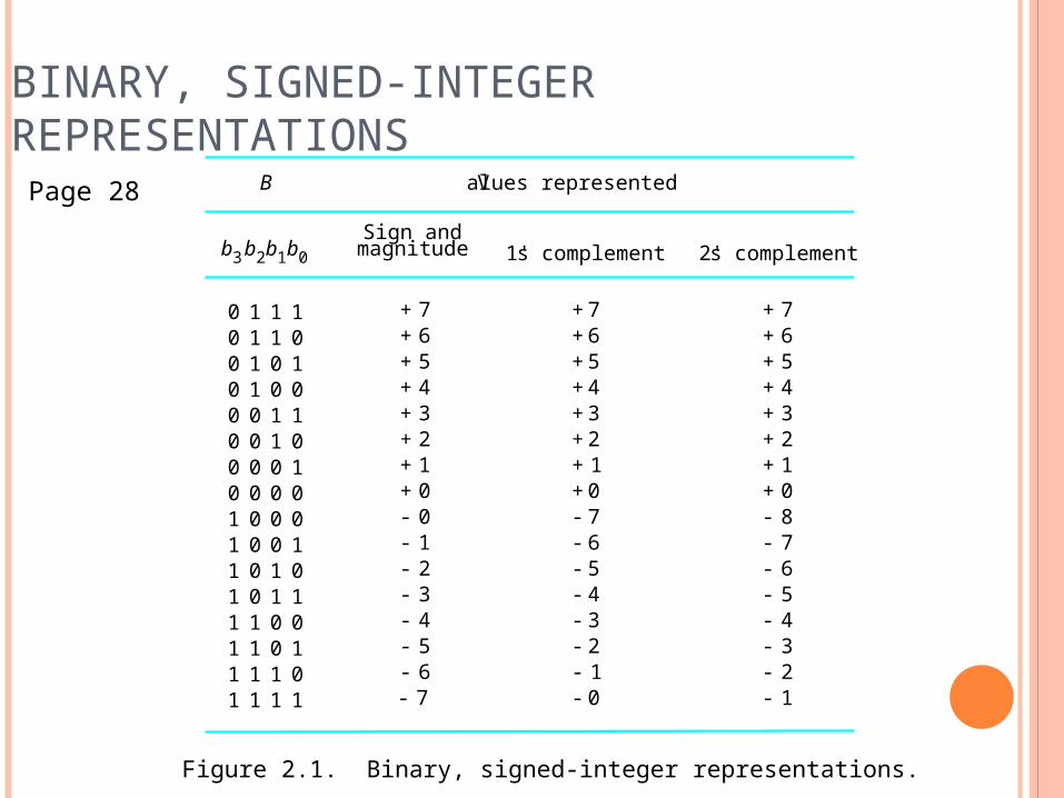
BINARY, SIGNED-INTEGER REPRESENTATIONS
0000000011111111
00000000
1111
1111
1100110000110011
1010101001010101
1+
1-
2+3+4+5+6+7+
2-3-4-5-6-7-
8-0+0-
1+2+3+4+5+6+7+
0+7-6-5-4-3-2-1-0-
1+2+3+4+5+6+7+
0+
7-6-5-4-3-2-1-
b3 b2b1b0Sign and
magnitude 1' s complement 2' s complement
B V alues represented
Figure 2.1. Binary, signed-integer representations.
Page 28
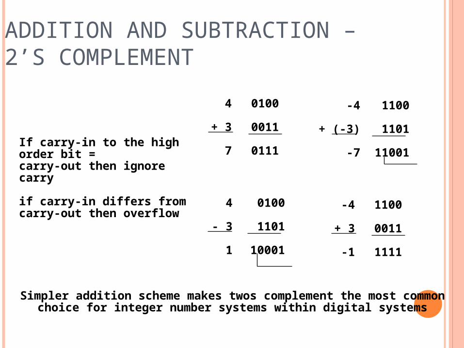
ADDITION AND SUBTRACTION – 2’S COMPLEMENT
4
+ 3
7
0100
0011
0111
-4
+ (-3)
-7
1100
1101
11001
4
- 3
1
0100
1101
10001
-4
+ 3
-1
1100
0011
1111
If carry-in to the high order bit =carry-out then ignorecarry
if carry-in differs fromcarry-out then overflow
Simpler addition scheme makes twos complement the most commonchoice for integer number systems within digital systems
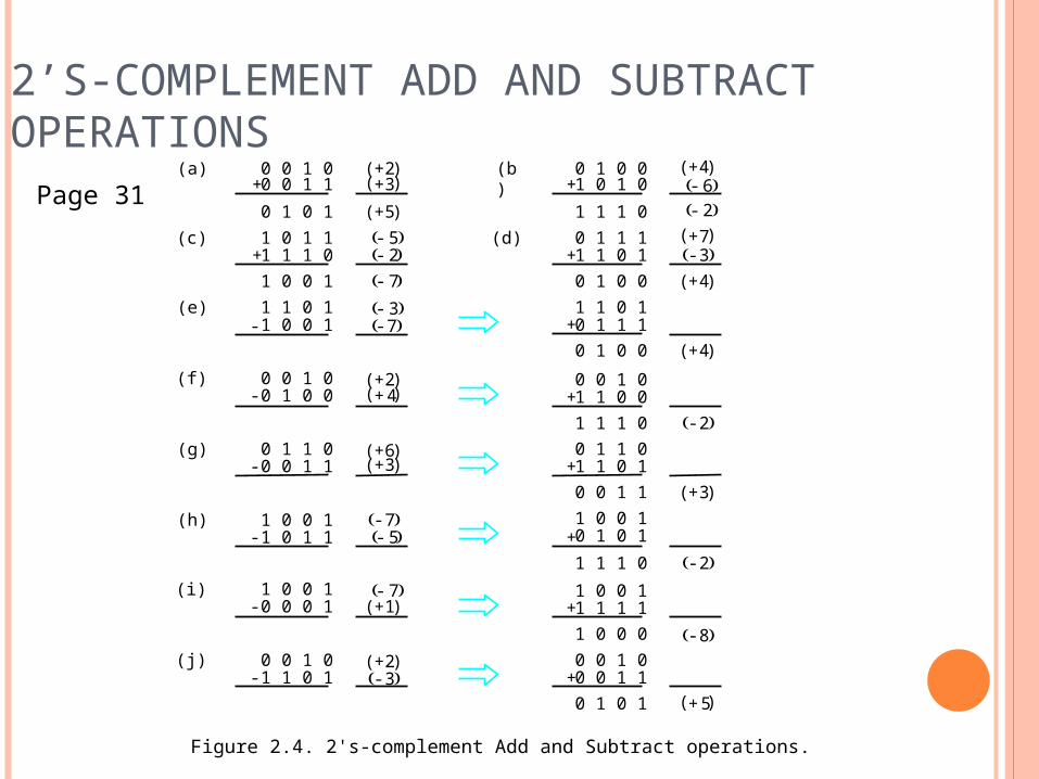
2’S-COMPLEMENT ADD AND SUBTRACT OPERATIONS
1 1 0 10 1 1 10 1 0 0
0 0 1 01 1 0 01 1 1 00 1 1 01 1 0 10 0 1 11 0 0 10 1 0 11 1 1 01 0 0 11 1 1 11 0 0 00 0 1 00 0 1 10 1 0 1
4+( )
2-
3+( )
2-
8-
5+( )+
+
+
+
+
+
1 1 1 0
0 1 0 01 0 1 0
0 1 1 11 1 0 10 1 0 0
6- 2-
4+( )
3- 4+( )
7+( )+
+(b)
(d)1 0 1 11 1 1 01 0 0 11 1 0 11 0 0 1
0 0 1 00 1 0 0
0 1 1 00 0 1 1
1 0 0 11 0 1 1
1 0 0 10 0 0 1
0 0 1 01 1 0 1
0 1 0 1
0 0 1 00 0 1 1
5-
2+( )3+( )
5+( )
2+( )4+( )
2- 7-
3- 7-
6+( )3+( )
1+( )
7- 5-
7-
2+( )3-
+
+
-
-
-
-
-
-
(a)
(c)
(e)
(f)
(g)
(h)
(i)
(j)
Figure 2.4. 2's-complement Add and Subtract operations.
Page 31
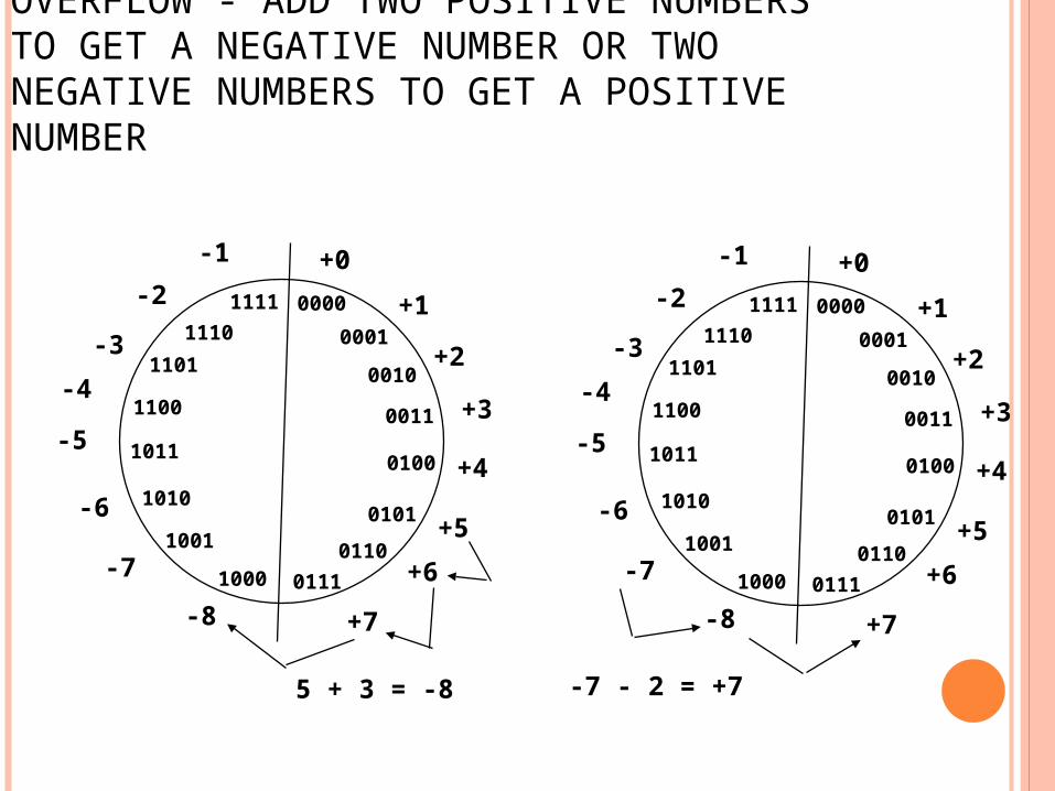
OVERFLOW - ADD TWO POSITIVE NUMBERS TO GET A NEGATIVE NUMBER OR TWO NEGATIVE NUMBERS TO GET A POSITIVE NUMBER
5 + 3 = -8 -7 - 2 = +7
00000001
0010
0011
1000
0101
0110
0100
1001
1010
1011
1100
1101
0111
11101111
+0+1
+2
+3
+4
+5+6
+7-8
-7
-6
-5
-4-3
-2-1
00000001
0010
0011
1000
0101
0110
0100
1001
1010
1011
1100
1101
0111
11101111
+0+1
+2
+3
+4
+5+6
+7-8
-7
-6
-5
-4-3
-2-1
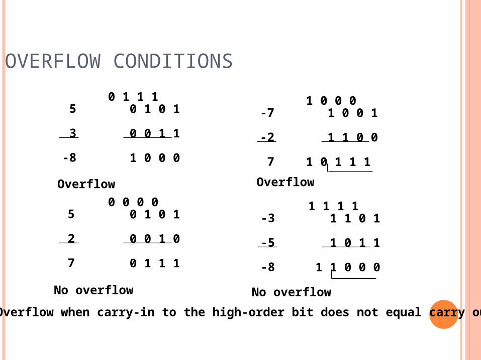
OVERFLOW CONDITIONS
5
3
-8
0 1 1 1 0 1 0 1
0 0 1 1
1 0 0 0
-7
-2
7
1 0 0 0 1 0 0 1
1 1 0 0
1 0 1 1 1
5
2
7
0 0 0 0 0 1 0 1
0 0 1 0
0 1 1 1
-3
-5
-8
1 1 1 1 1 1 0 1
1 0 1 1
1 1 0 0 0
Overflow Overflow
No overflow No overflowOverflow when carry-in to the high-order bit does not equal carry out
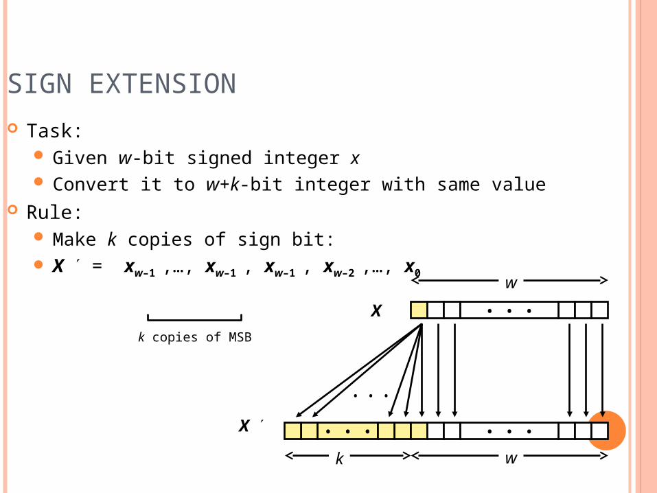
SIGN EXTENSION Task:
Given w-bit signed integer x Convert it to w+k-bit integer with same value
Rule: Make k copies of sign bit: X = xw–1 ,…, xw–1 , xw–1 , xw–2 ,…, x0
k copies of MSB
• • •X
X • • • • • •
• • •
w
wk
SIGN EXTENSION EXAMPLE
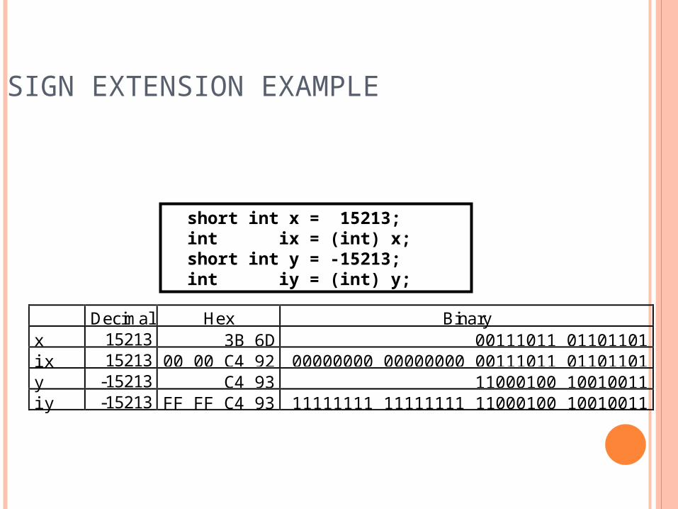
short int x = 15213; int ix = (int) x; short int y = -15213; int iy = (int) y;
Decimal Hex Binaryx 15213 3B 6D 00111011 01101101ix 15213 00 00 C4 92 00000000 00000000 00111011 01101101y -15213 C4 93 11000100 10010011iy -15213 FF FF C4 93 11111111 11111111 11000100 10010011
MEMORY LOCATIONS,
ADDRESSES, AND OPERATIONS
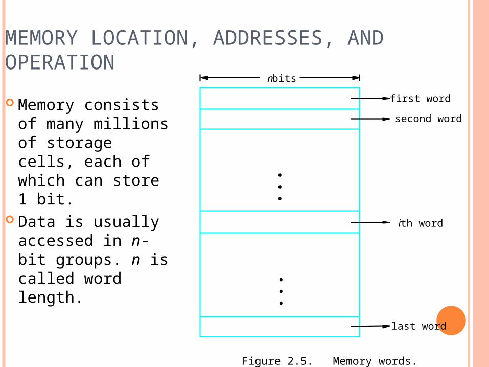
MEMORY LOCATION, ADDRESSES, AND OPERATION Memory consists
of many millions of storage cells, each of which can store 1 bit.
Data is usually accessed in n-bit groups. n is called word length.
second word
first word
Figure 2.5. Memory words.
n bits
last word
i th word
•••
•••
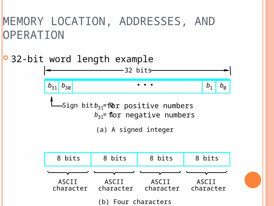
MEMORY LOCATION, ADDRESSES, AND OPERATION 32-bit word length example
(b) Four characters
charactercharactercharacter character
(a) A signed integer
Sign bit: for positive numbers for negative numbers
ASCIIASCIIASCIIASCII
32 bits
8 bits 8 bits 8 bits 8 bits
b31 b30 b1 b0
b31 0=b31 1=
• • •
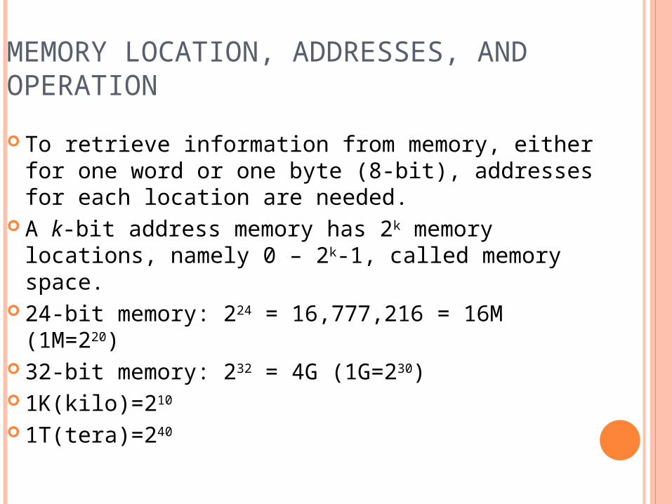
MEMORY LOCATION, ADDRESSES, AND OPERATION To retrieve information from memory, either for
one word or one byte (8-bit), addresses for each location are needed.
A k-bit address memory has 2k memory locations, namely 0 – 2k-1, called memory space.
24-bit memory: 224 = 16,777,216 = 16M (1M=220)
32-bit memory: 232 = 4G (1G=230) 1K(kilo)=210
1T(tera)=240
MEMORY LOCATION, ADDRESSES, AND OPERATION It is impractical to assign distinct addresses to
individual bit locations in the memory. The most practical assignment is to have
successive addresses refer to successive byte locations in the memory – byte-addressable memory.
Byte locations have addresses 0, 1, 2, … If word length is 32 bits, they successive words are located at addresses 0, 4, 8,…
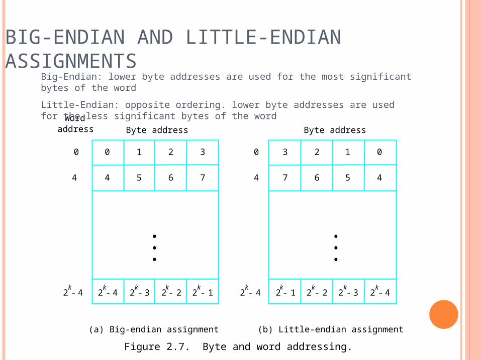
BIG-ENDIAN AND LITTLE-ENDIAN ASSIGNMENTS
2k
4- 2k
3- 2k
2- 2k
1- 2k
4-2k
4-
0 1 2 3
4 5 6 7
0 0
4
2k
1- 2k
2- 2k
3- 2k
4-
3 2 1 0
7 6 5 4
Byte addressByte address
(a) Big-endian assignment (b) Little-endian assignment
4
Wordaddress
•••
•••
Figure 2.7. Byte and word addressing.
Big-Endian: lower byte addresses are used for the most significant bytes of the word
Little-Endian: opposite ordering. lower byte addresses are used for the less significant bytes of the word
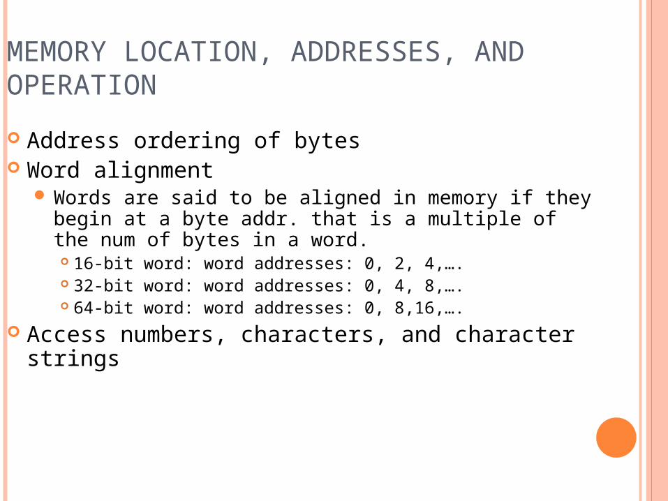
MEMORY LOCATION, ADDRESSES, AND OPERATION Address ordering of bytes Word alignment
Words are said to be aligned in memory if they begin at a byte addr. that is a multiple of the num of bytes in a word. 16-bit word: word addresses: 0, 2, 4,…. 32-bit word: word addresses: 0, 4, 8,…. 64-bit word: word addresses: 0, 8,16,….
Access numbers, characters, and character strings
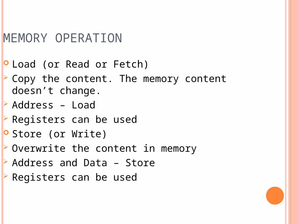
MEMORY OPERATION Load (or Read or Fetch) Copy the content. The memory content doesn’t
change. Address – Load Registers can be used Store (or Write) Overwrite the content in memory Address and Data – Store Registers can be used
INSTRUCTION AND INSTRUCTION SEQUENCING
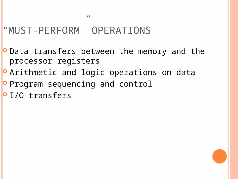
“MUST-PERFORM” OPERATIONS Data transfers between the memory and the
processor registers Arithmetic and logic operations on data Program sequencing and control I/O transfers
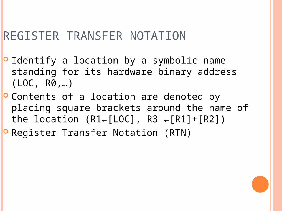
REGISTER TRANSFER NOTATION Identify a location by a symbolic name standing
for its hardware binary address (LOC, R0,…) Contents of a location are denoted by placing
square brackets around the name of the location (R1←[LOC], R3 ←[R1]+[R2])
Register Transfer Notation (RTN)
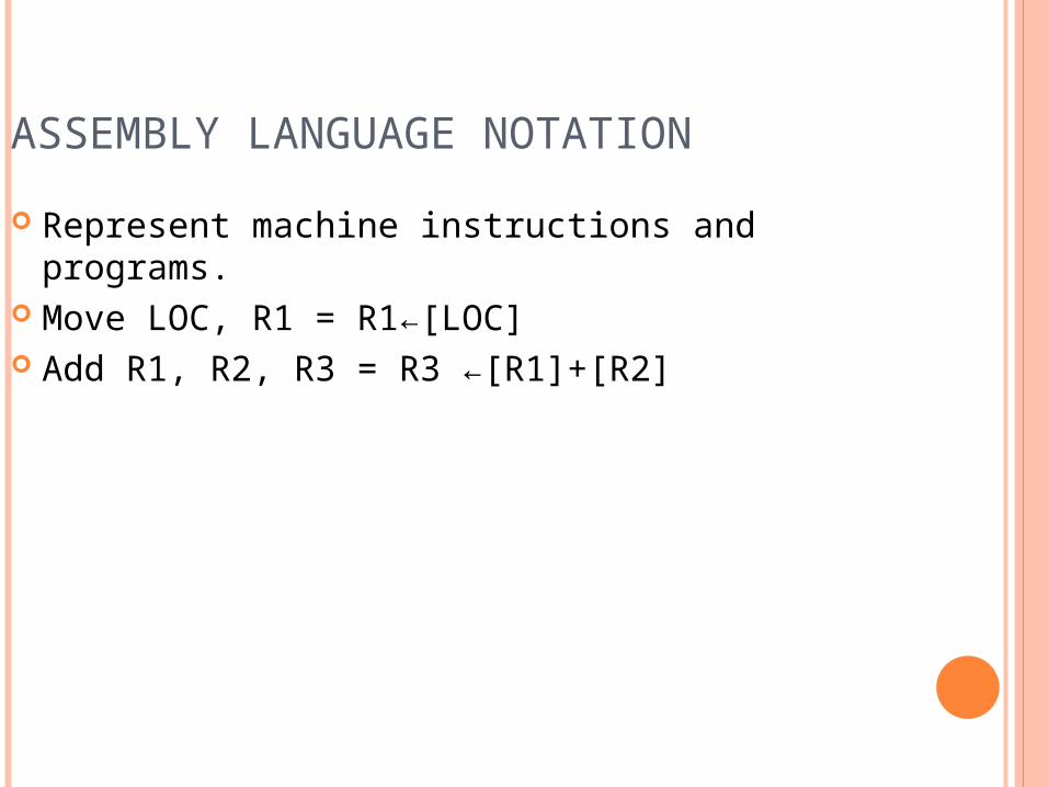
ASSEMBLY LANGUAGE NOTATION Represent machine instructions and programs. Move LOC, R1 = R1←[LOC] Add R1, R2, R3 = R3 ←[R1]+[R2]
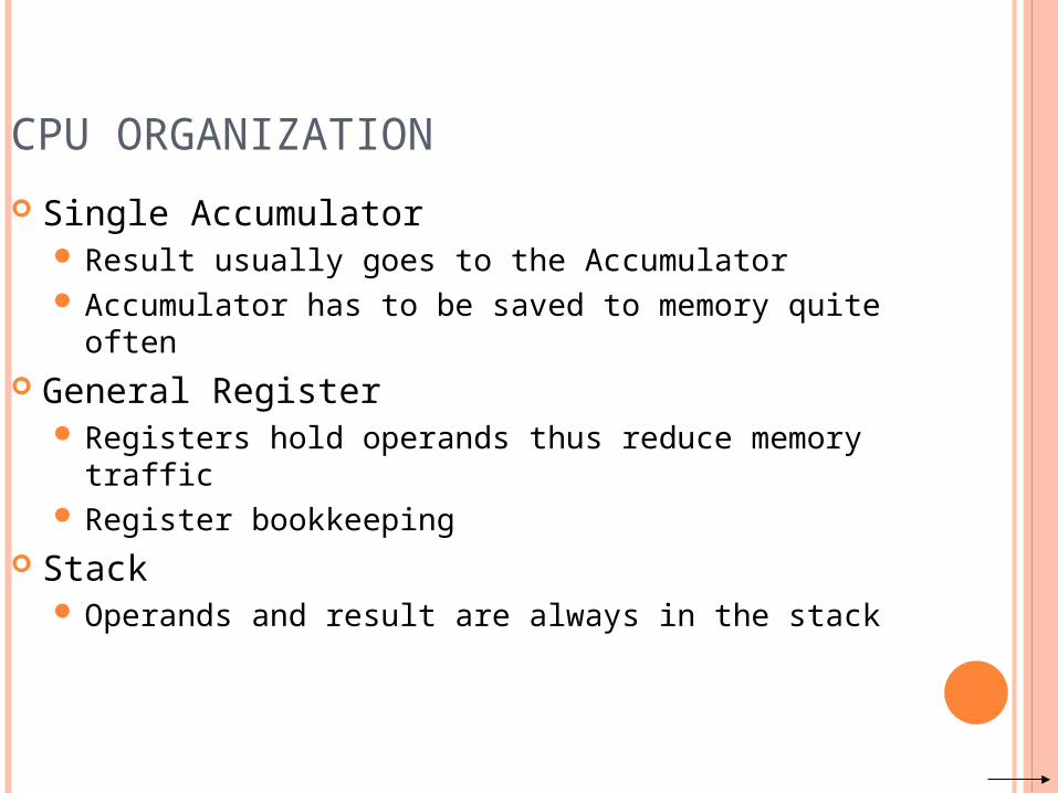
CPU ORGANIZATION Single Accumulator
Result usually goes to the Accumulator Accumulator has to be saved to memory quite often
General Register Registers hold operands thus reduce memory traffic Register bookkeeping
Stack Operands and result are always in the stack
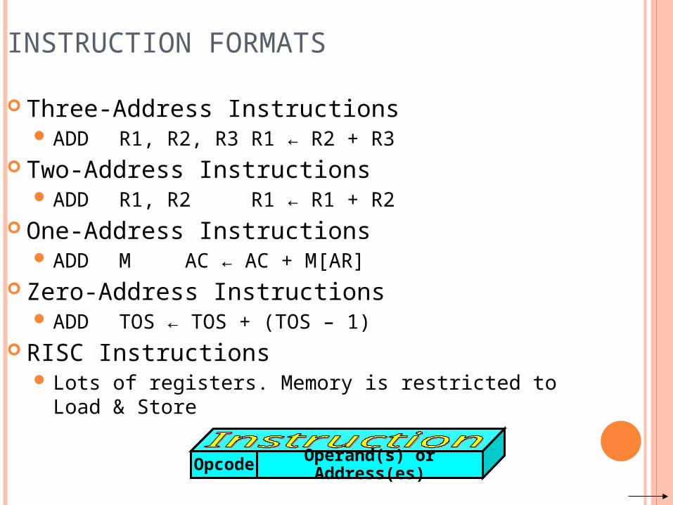
INSTRUCTION FORMATS Three-Address Instructions
ADD R1, R2, R3 R1 ← R2 + R3 Two-Address Instructions
ADD R1, R2 R1 ← R1 + R2 One-Address Instructions
ADD M AC ← AC + M[AR] Zero-Address Instructions
ADD TOS ← TOS + (TOS – 1) RISC Instructions
Lots of registers. Memory is restricted to Load & Store
Opcode Operand(s) or Address(es)
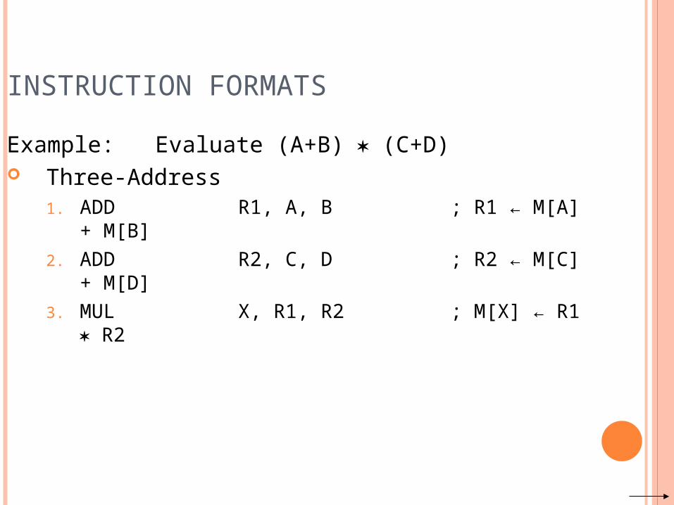
INSTRUCTION FORMATSExample: Evaluate (A+B) (C+D) Three-Address
1. ADD R1, A, B ; R1 ← M[A] + M[B]
2. ADD R2, C, D ; R2 ← M[C] + M[D]
3. MUL X, R1, R2 ; M[X] ← R1 R2
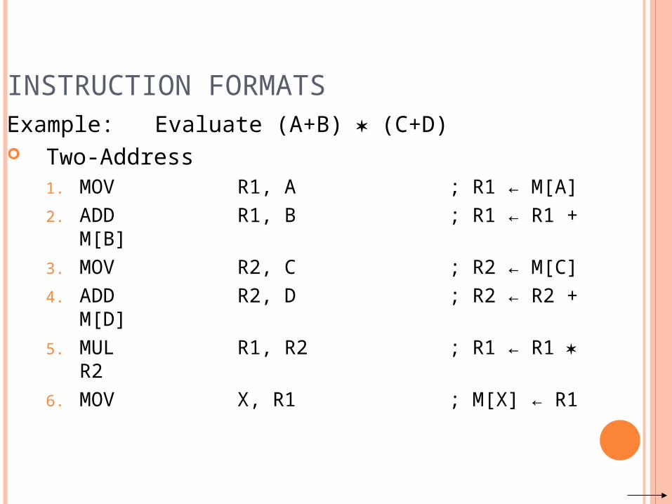
INSTRUCTION FORMATSExample: Evaluate (A+B) (C+D) Two-Address
1. MOV R1, A ; R1 ← M[A]2. ADD R1, B ; R1 ← R1 +
M[B]3. MOV R2, C ; R2 ← M[C]4. ADD R2, D ; R2 ← R2 +
M[D]5. MUL R1, R2 ; R1 ← R1 R26. MOV X, R1 ; M[X] ← R1
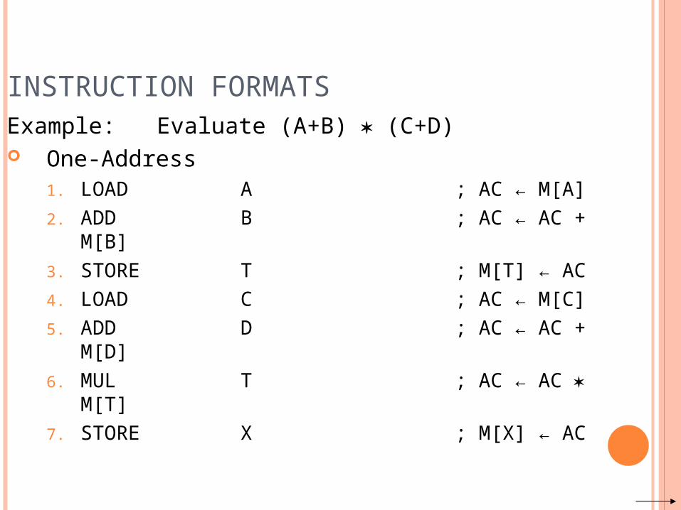
INSTRUCTION FORMATSExample: Evaluate (A+B) (C+D) One-Address
1. LOAD A ; AC ← M[A]2. ADD B ; AC ← AC +
M[B]3. STORE T ; M[T] ← AC 4. LOAD C ; AC ← M[C]5. ADD D ; AC ← AC +
M[D]6. MUL T ; AC ← AC
M[T]7. STORE X ; M[X] ← AC
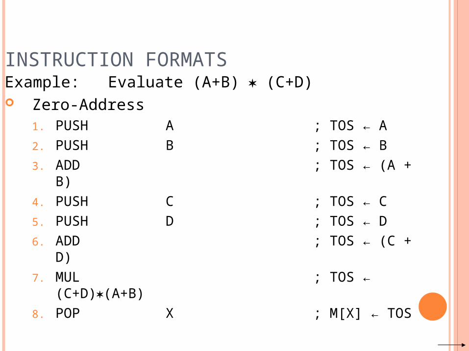
INSTRUCTION FORMATSExample: Evaluate (A+B) (C+D) Zero-Address
1. PUSH A ; TOS ← A2. PUSH B ; TOS ← B3. ADD ; TOS ← (A + B)4. PUSH C ; TOS ← C5. PUSH D ; TOS ← D6. ADD ; TOS ← (C +
D)7. MUL ; TOS ←
(C+D)(A+B)8. POP X ; M[X] ← TOS
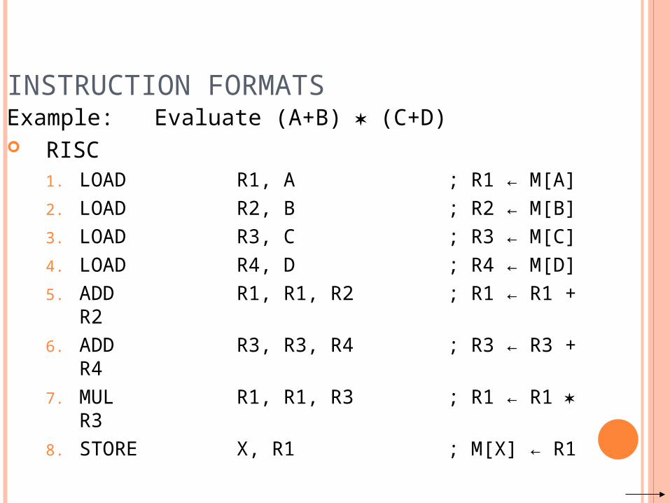
INSTRUCTION FORMATSExample: Evaluate (A+B) (C+D) RISC
1. LOAD R1, A ; R1 ← M[A]2. LOAD R2, B ; R2 ← M[B]3. LOAD R3, C ; R3 ← M[C]4. LOAD R4, D ; R4 ← M[D]5. ADD R1, R1, R2 ; R1 ← R1 + R26. ADD R3, R3, R4 ; R3 ← R3 + R47. MUL R1, R1, R3 ; R1 ← R1 R38. STORE X, R1 ; M[X] ← R1
USING REGISTERS Registers are faster Shorter instructions
The number of registers is smaller (e.g. 32 registers need 5 bits)
Potential speedup Minimize the frequency with which data is moved
back and forth between the memory and processor registers.
INSTRUCTION EXECUTION AND STRAIGHT-LINE SEQUENCING
R0,C
B,R0
A,R0
Movei + 8
Begin execution here Movei
ContentsAddress
C
B
A
the programData for
segmentprogram3-instruction
Addi + 4
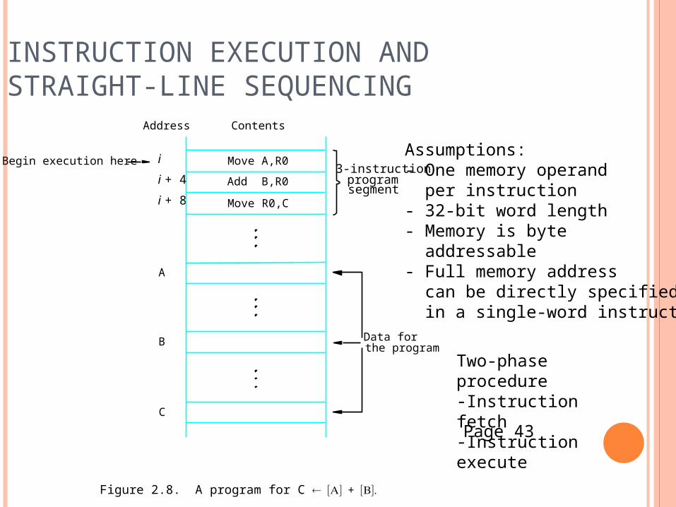
Figure 2.8. A program for C +
Assumptions:- One memory operand per instruction- 32-bit word length- Memory is byte addressable- Full memory address can be directly specified in a single-word instruction
Two-phase procedure-Instruction fetch-Instruction execute
Page 43
BRANCHING
NUMn
NUM2
NUM1
R0,SUM
NUMn ,R0
NUM3,R0
NUM2,R0
NUM1,R0
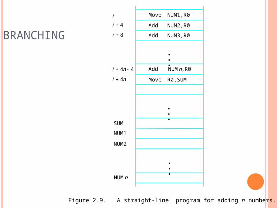
Figure 2.9. A straight-line program for adding n numbers.
Add
Add
Move
SUM
i
Move
Add
i 4n+
i 4n 4-+
i 8+
i 4+
•••
•••
•••
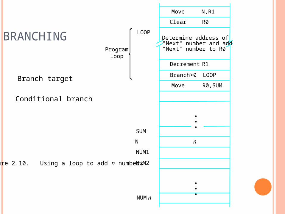
BRANCHING
N,R1Move
NUMn
NUM2
NUM1
R0,SUM
R1
"Next" number to R0
Figure 2.10. Using a loop to add n numbers.
LOOP
Decrement
Move
LOOP
loopProgram
Determine address of"Next" number and add
N
SUM
n
R0Clear
Branch>0
•••
•••
Branch target
Conditional branch
CONDITION CODES Condition code flags Condition code register / status register N (negative) Z (zero) V (overflow) C (carry) Different instructions affect different flags
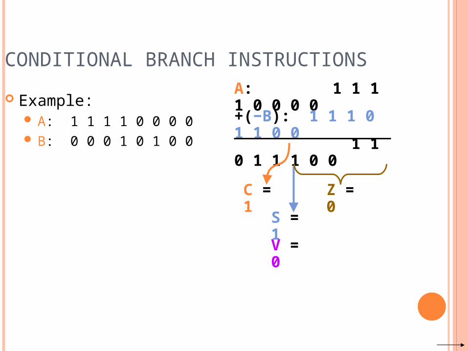
CONDITIONAL BRANCH INSTRUCTIONS Example:
A: 1 1 1 1 0 0 0 0 B: 0 0 0 1 0 1 0 0
A: 1 1 1 1 0 0 0 0
+(−B): 1 1 1 0 1 1 0 0
1 1 0 1 1 1 0 0
C = 1
S = 1
V = 0
Z = 0
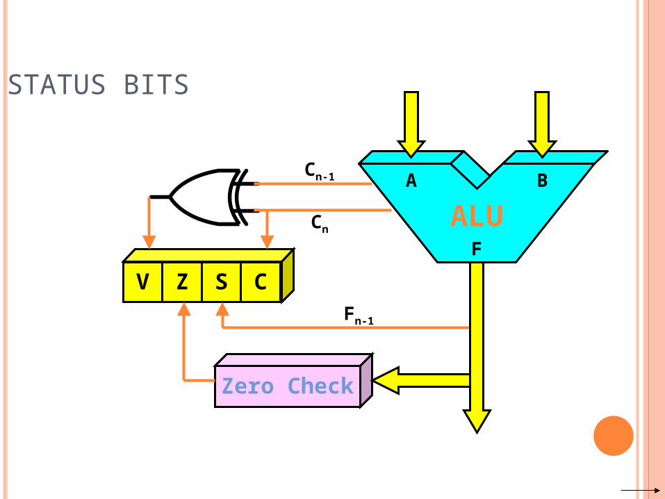
STATUS BITS
ALU
V Z S C
Zero Check
Cn
Cn-1
Fn-1
A B
F
ADDRESSING MODES
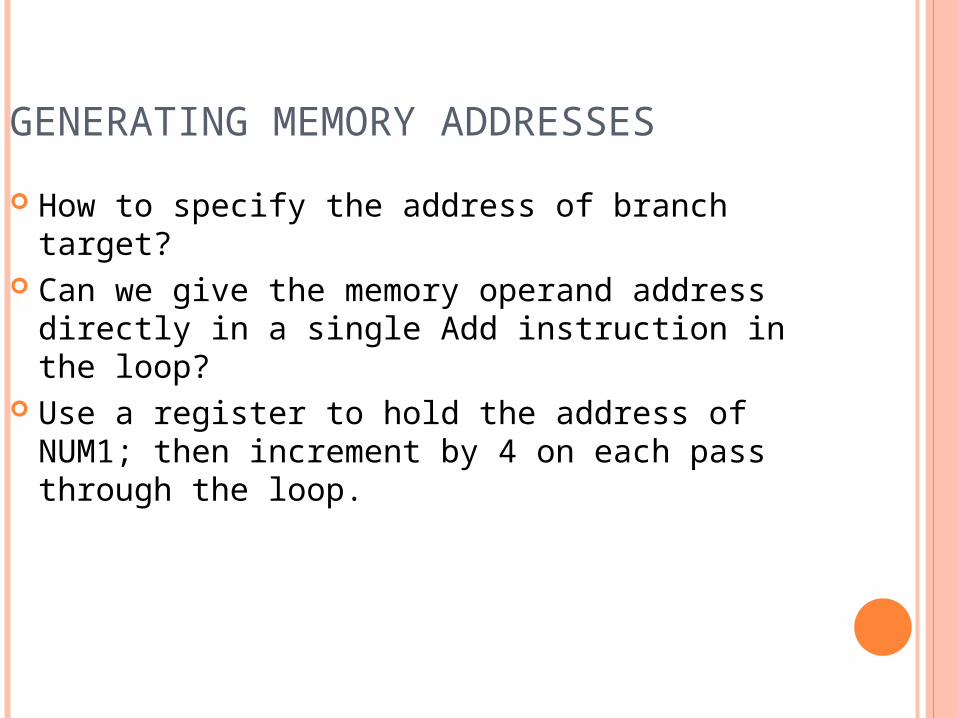
GENERATING MEMORY ADDRESSES How to specify the address of branch target? Can we give the memory operand address directly
in a single Add instruction in the loop? Use a register to hold the address of NUM1; then
increment by 4 on each pass through the loop.
ADDRESSING MODES
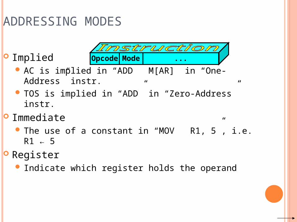
Implied AC is implied in “ADD M[AR]” in “One-Address” instr. TOS is implied in “ADD” in “Zero-Address” instr.
Immediate The use of a constant in “MOV R1, 5”, i.e. R1 ← 5
Register Indicate which register holds the operand
Opcode Mode ...
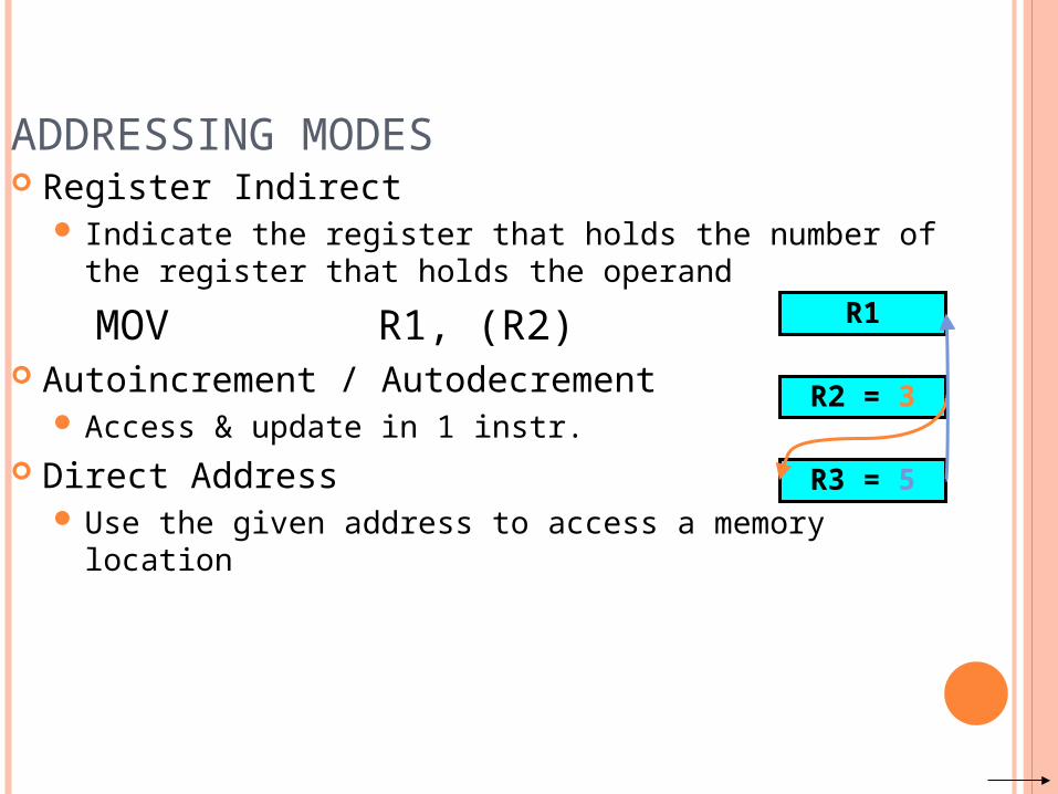
ADDRESSING MODES Register Indirect
Indicate the register that holds the number of the register that holds the operandMOV R1, (R2)
Autoincrement / Autodecrement Access & update in 1 instr.
Direct Address Use the given address to access a memory location
R1
R2 = 3
R3 = 5
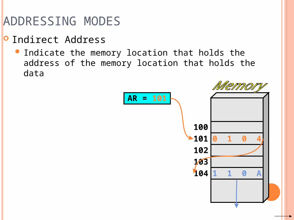
ADDRESSING MODES Indirect Address
Indicate the memory location that holds the address of the memory location that holds the data
AR = 101
100101102103104
0 1 0 4
1 1 0 A
100101102103104
012
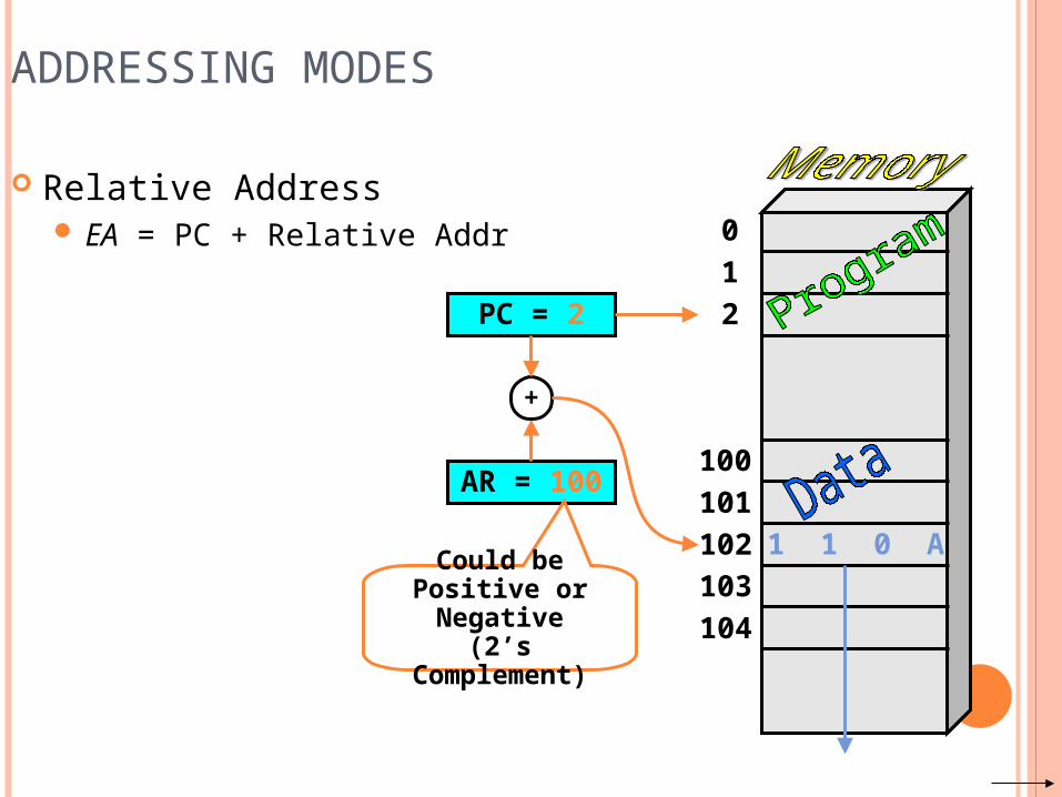
ADDRESSING MODES
Relative Address EA = PC + Relative Addr
AR = 100
1 1 0 A
PC = 2
+
Could be Positive or Negative
(2’s Complement)
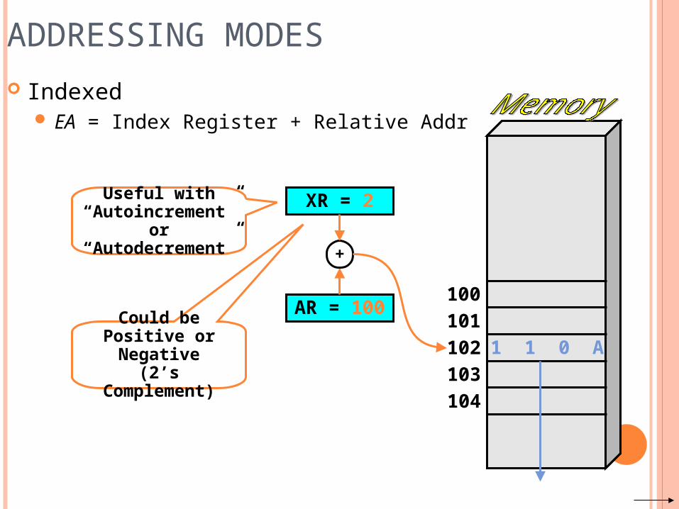
ADDRESSING MODES Indexed
EA = Index Register + Relative Addr
100101102103104
AR = 100
1 1 0 A
XR = 2
+
Could be Positive or Negative
(2’s Complement)
Useful with “Autoincrement” or “Autodecrement”
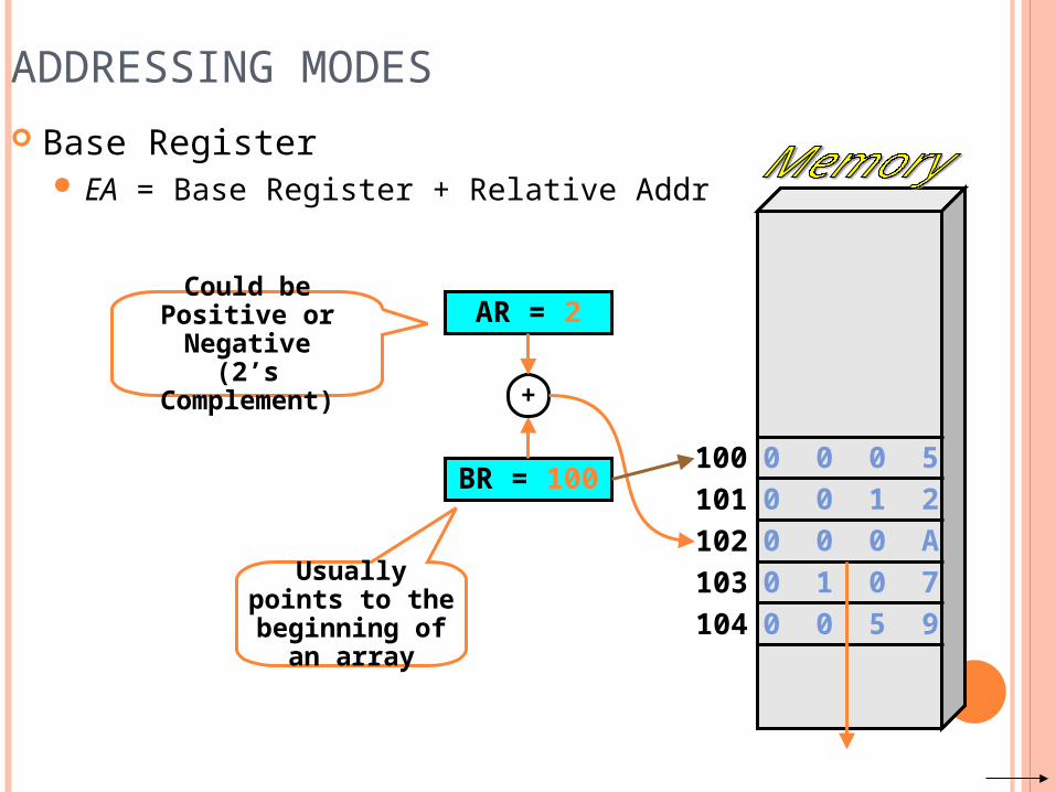
ADDRESSING MODES Base Register
EA = Base Register + Relative Addr
100101102103104
BR = 100
0 0 0 A
AR = 2
+
Could be Positive or Negative
(2’s Complement)
Usually points to the beginning
of an array
0 0 0 50 0 1 2
0 1 0 70 0 5 9
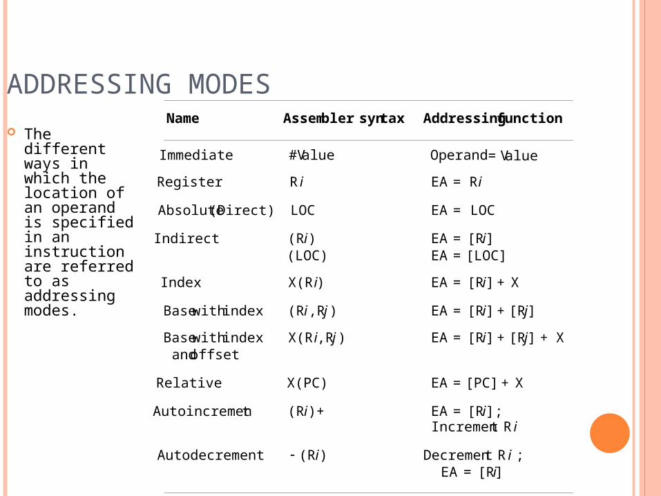
ADDRESSING MODES The different
ways in which the location of an operand is specified in an instruction are referred to as addressing modes.
Name Assembler syntax Addressingfunction
Immediate #Value Operand=ValueRegister R i EA = Ri
Absolute(Direct) LOC EA = LOCIndirect (Ri ) EA = [Ri]
(LOC) EA = [LOC]Index X(Ri) EA = [Ri]+ XBasewithindex (Ri ,Rj ) EA = [Ri]+ [Rj]Basewithindex X(Ri,Rj ) EA = [Ri]+ [Rj] + Xandoffset
Relative X(PC) EA = [PC] + XAutoincrement (Ri)+ EA = [Ri] ;
Increment Ri
Autodecrement (Ri ) Decrement R i ;EA = [Ri]
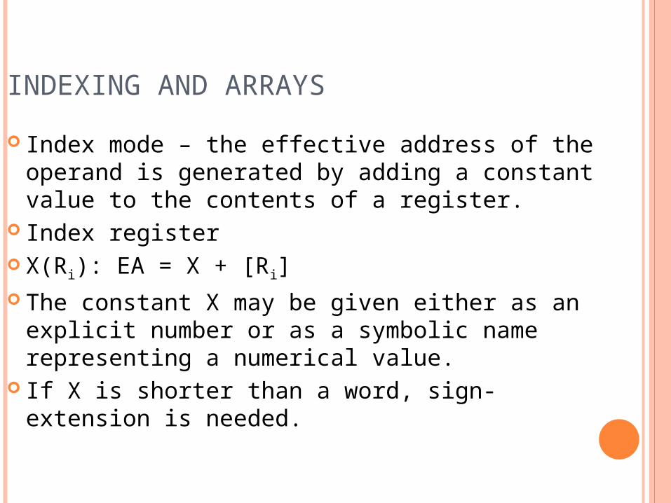
INDEXING AND ARRAYS Index mode – the effective address of the
operand is generated by adding a constant value to the contents of a register.
Index register X(Ri): EA = X + [Ri] The constant X may be given either as an
explicit number or as a symbolic name representing a numerical value.
If X is shorter than a word, sign-extension is needed.
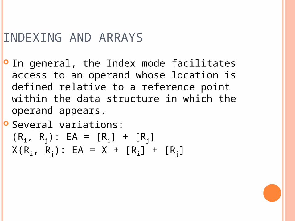
INDEXING AND ARRAYS In general, the Index mode facilitates access to an
operand whose location is defined relative to a reference point within the data structure in which the operand appears.
Several variations:(Ri, Rj): EA = [Ri] + [Rj]X(Ri, Rj): EA = X + [Ri] + [Rj]
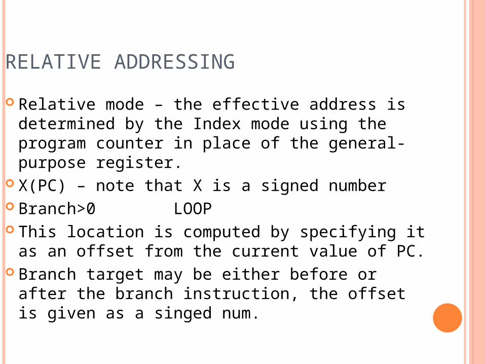
RELATIVE ADDRESSING Relative mode – the effective address is
determined by the Index mode using the program counter in place of the general-purpose register.
X(PC) – note that X is a signed number Branch>0 LOOP This location is computed by specifying it as an
offset from the current value of PC. Branch target may be either before or after the
branch instruction, the offset is given as a singed num.
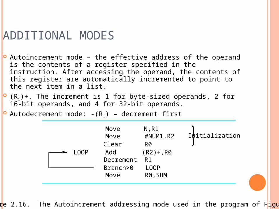
ADDITIONAL MODES Autoincrement mode – the effective address of the operand is
the contents of a register specified in the instruction. After accessing the operand, the contents of this register are automatically incremented to point to the next item in a list.
(Ri)+. The increment is 1 for byte-sized operands, 2 for 16-bit operands, and 4 for 32-bit operands.
Autodecrement mode: -(Ri) – decrement first
R0Clear
R0,SUM
R1(R2)+,R0
Figure 2.16. The Autoincrement addressing mode used in the program of Figure 2.12.
Initialization
Move
LOOP AddDecrement
LOOP
#NUM1,R2N,R1Move
Move
Branch>0

ASSEMBLY LANGUAGE
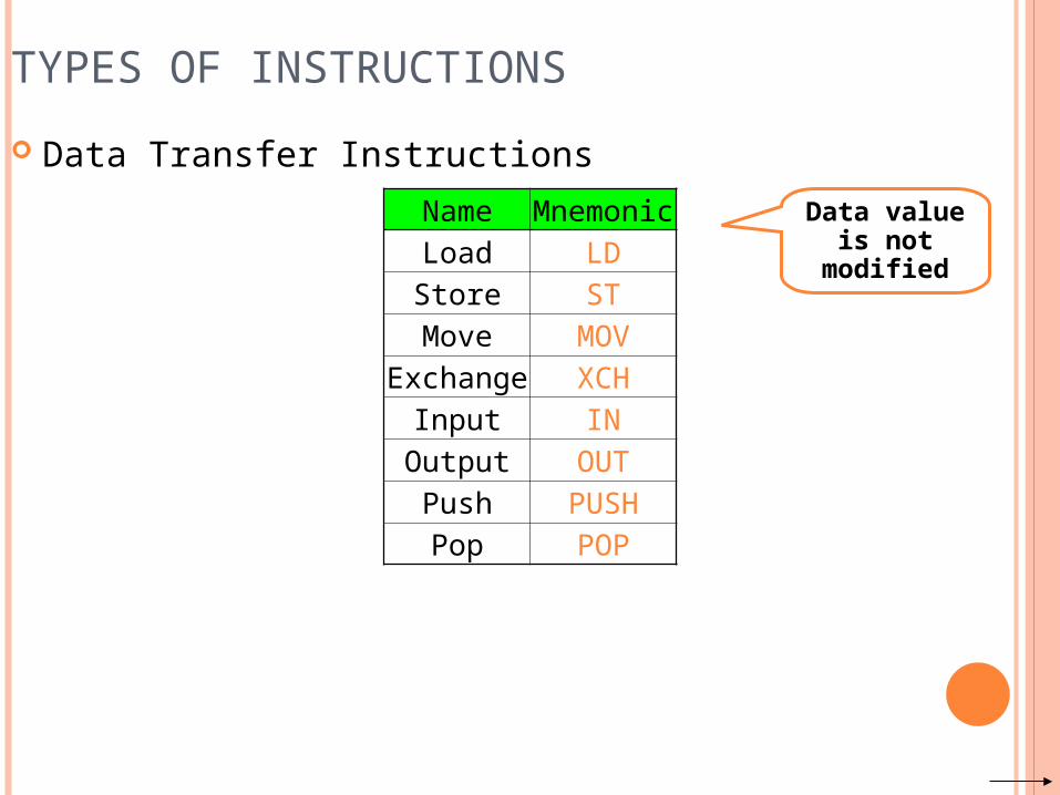
TYPES OF INSTRUCTIONS Data Transfer Instructions
Name MnemonicLoad LDStore STMove MOV
Exchange XCHInput IN
Output OUTPush PUSHPop POP
Data value is not modified
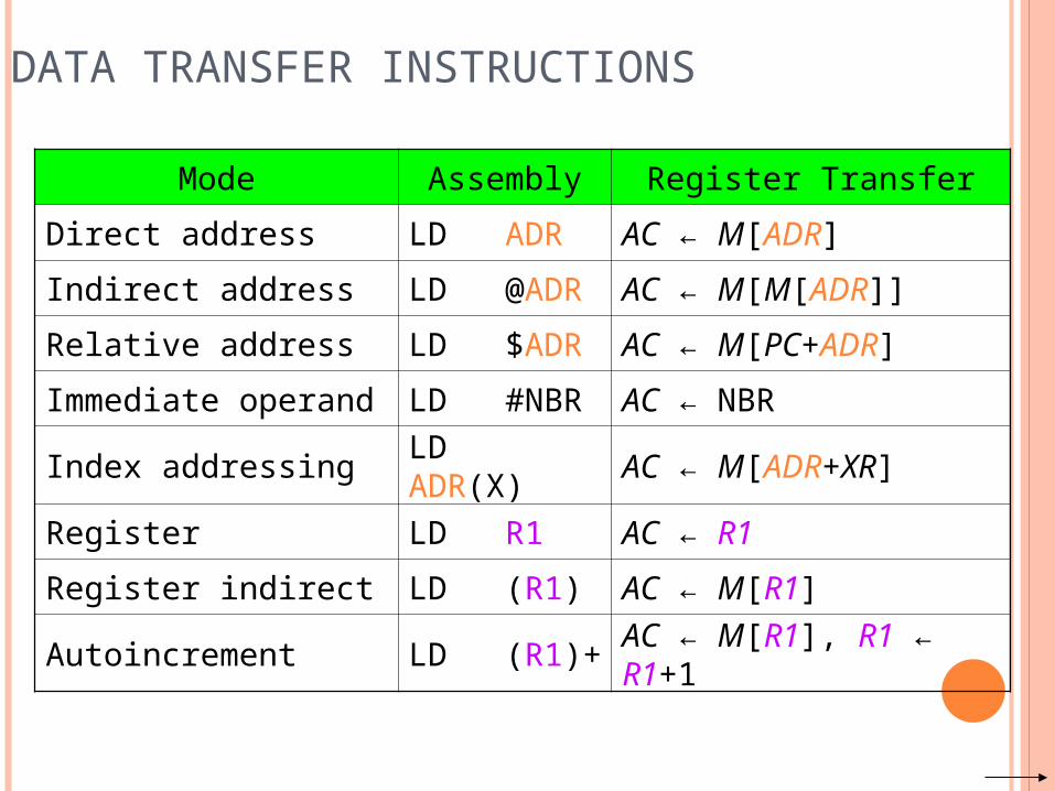
DATA TRANSFER INSTRUCTIONS
Mode Assembly Register Transfer
Direct address LD ADR AC ← M[ADR]
Indirect address LD @ADR AC ← M[M[ADR]]
Relative address LD $ADR AC ← M[PC+ADR]
Immediate operand LD #NBR AC ← NBR
Index addressing LD ADR(X) AC ← M[ADR+XR]
Register LD R1 AC ← R1
Register indirect LD (R1) AC ← M[R1]
Autoincrement LD (R1)+ AC ← M[R1], R1 ← R1+1
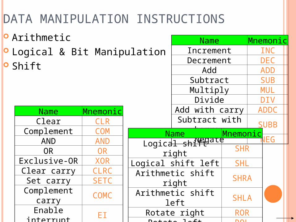
DATA MANIPULATION INSTRUCTIONS Arithmetic Logical & Bit Manipulation Shift
Name MnemonicIncrement INCDecrement DEC
Add ADDSubtract SUBMultiply MULDivide DIV
Add with carry ADDCSubtract with borrow SUBB
Negate NEG
Name MnemonicClear CLR
Complement COMAND ANDOR OR
Exclusive-OR XORClear carry CLRCSet carry SETC
Complement carry COMC
Enable interrupt EIDisable interrupt DI
Name MnemonicLogical shift right SHRLogical shift left SHL
Arithmetic shift right SHRAArithmetic shift left SHLA
Rotate right RORRotate left ROL
Rotate right through carry RORC
Rotate left through carry ROLC
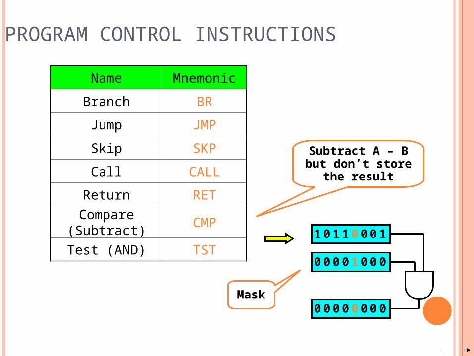
PROGRAM CONTROL INSTRUCTIONSName Mnemonic
Branch BR
Jump JMP
Skip SKP
Call CALL
Return RETCompare (Subtract) CMP
Test (AND) TST
Subtract A – B but don’t store the result
1 0 1 1 0 0 0 1
0 0 0 0 1 0 0 0
0 0 0 0 0 0 0 0Mask
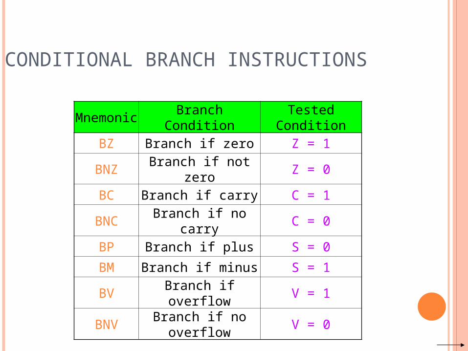
CONDITIONAL BRANCH INSTRUCTIONS
Mnemonic Branch Condition Tested ConditionBZ Branch if zero Z = 1
BNZ Branch if not zero Z = 0BC Branch if carry C = 1
BNC Branch if no carry C = 0BP Branch if plus S = 0BM Branch if minus S = 1BV Branch if overflow V = 1
BNV Branch if no overflow V = 0
BASIC INPUT/OUTPUT
OPERATIONS
I/O The data on which the instructions operate are not
necessarily already stored in memory. Data need to be transferred between processor
and outside world (disk, keyboard, etc.) I/O operations are essential, the way they are
performed can have a significant effect on the performance of the computer.
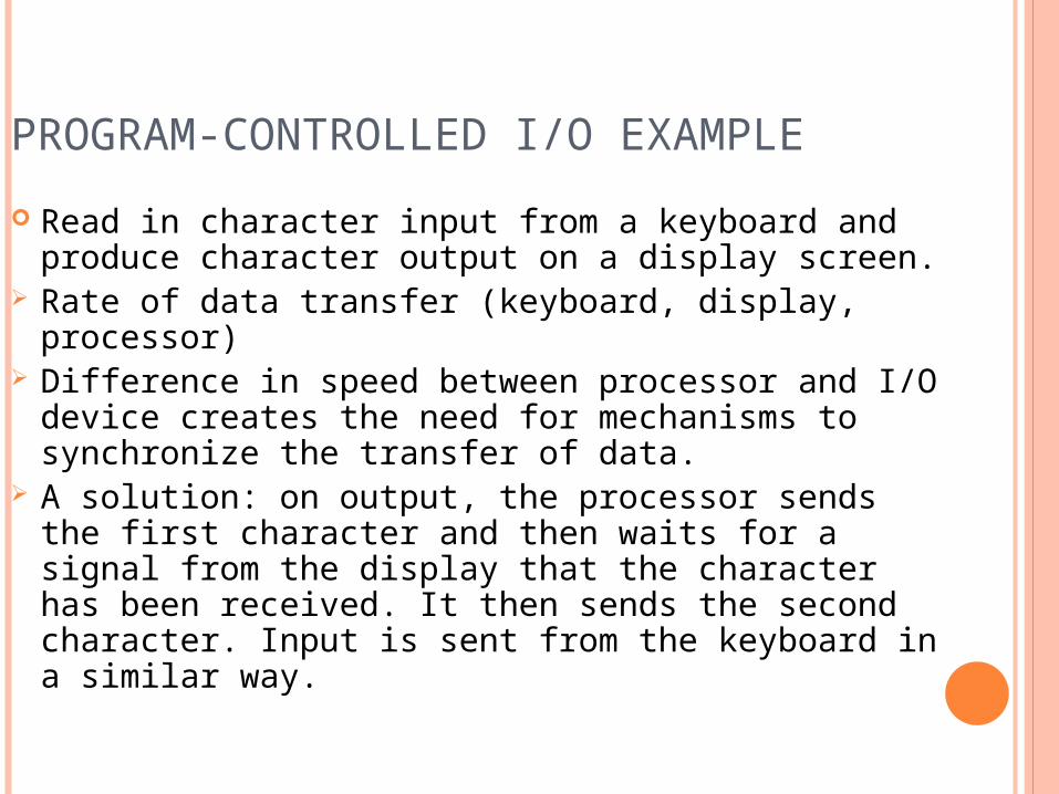
PROGRAM-CONTROLLED I/O EXAMPLE Read in character input from a keyboard and
produce character output on a display screen. Rate of data transfer (keyboard, display,
processor) Difference in speed between processor and I/O
device creates the need for mechanisms to synchronize the transfer of data.
A solution: on output, the processor sends the first character and then waits for a signal from the display that the character has been received. It then sends the second character. Input is sent from the keyboard in a similar way.
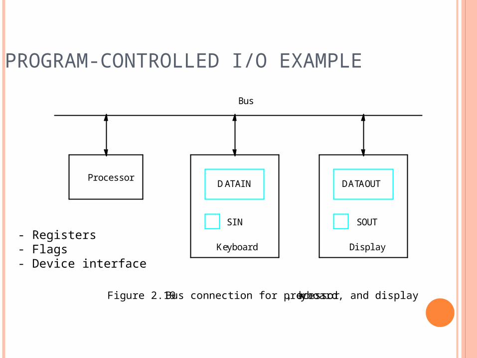
PROGRAM-CONTROLLED I/O EXAMPLE
DATAIN DATAOUT
SIN SOUT
Keyboard Display
Bus
Figure 2.19 Bus connection for processor, keyboard, and display.
Processor
- Registers- Flags- Device interface
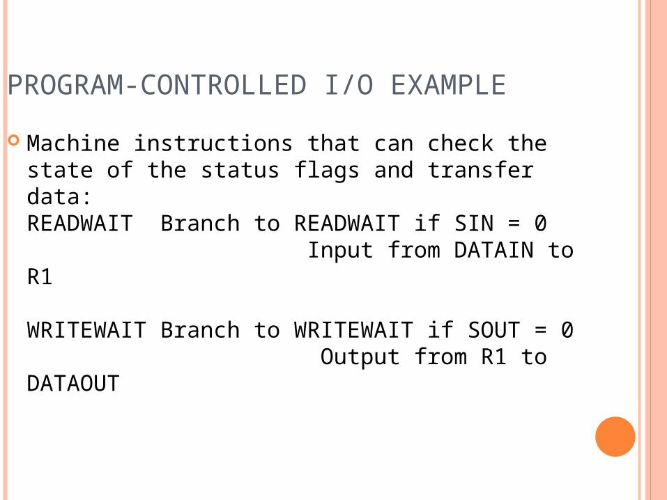
PROGRAM-CONTROLLED I/O EXAMPLE Machine instructions that can check the state of
the status flags and transfer data:READWAIT Branch to READWAIT if SIN = 0 Input from DATAIN to R1
WRITEWAIT Branch to WRITEWAIT if SOUT = 0 Output from R1 to DATAOUT
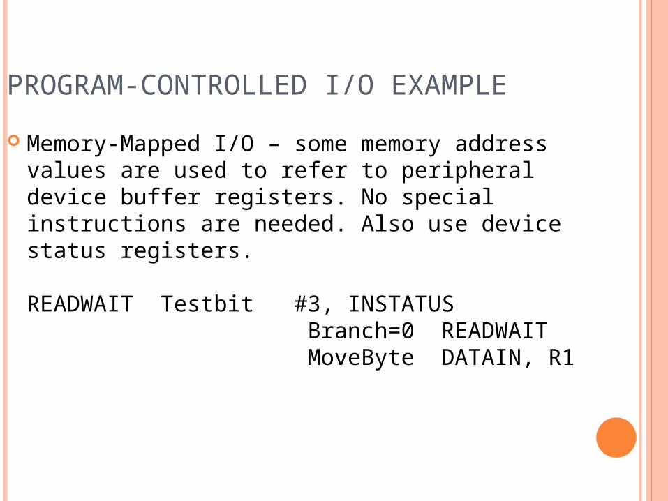
PROGRAM-CONTROLLED I/O EXAMPLE Memory-Mapped I/O – some memory address
values are used to refer to peripheral device buffer registers. No special instructions are needed. Also use device status registers.
READWAIT Testbit #3, INSTATUS Branch=0 READWAIT MoveByte DATAIN, R1
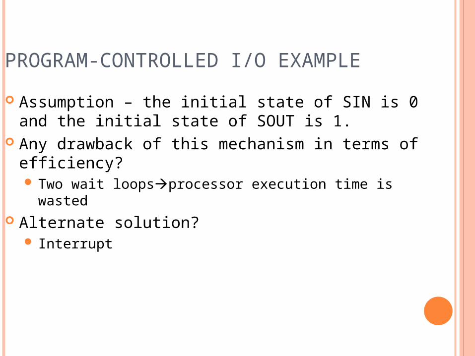
PROGRAM-CONTROLLED I/O EXAMPLE Assumption – the initial state of SIN is 0 and the
initial state of SOUT is 1. Any drawback of this mechanism in terms of
efficiency? Two wait loopsprocessor execution time is wasted
Alternate solution? Interrupt

STACKS
HOME WORK For each Addressing modes mentioned before,
state one example for each addressing mode stating the specific benefit for using such addressing mode for such an application.
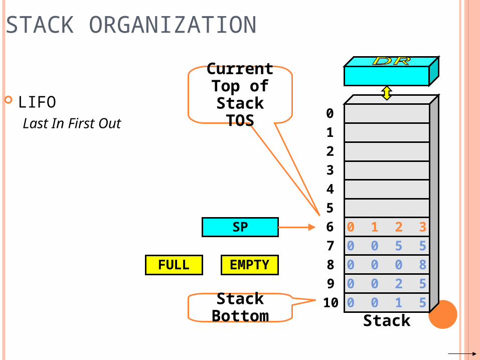
STACK ORGANIZATION
LIFOLast In First Out
SP
Stack Bottom
CurrentTop of Stack
TOS 01234
78910
56
Stack
0 0 5 50 0 0 80 0 2 50 0 1 5
0 1 2 3
FULL EMPTY
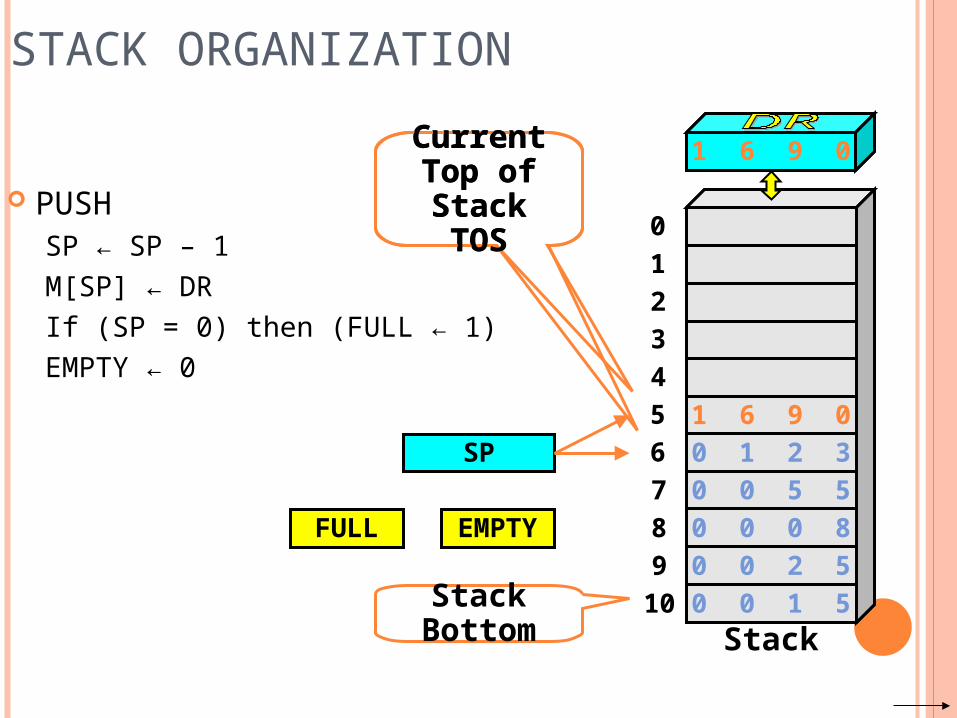
STACK ORGANIZATION
PUSHSP ← SP – 1M[SP] ← DRIf (SP = 0) then (FULL ← 1)EMPTY ← 0
SP
Stack Bottom
CurrentTop of Stack
TOS 01234
78910
56
Stack
0 0 5 50 0 0 80 0 2 50 0 1 5
0 1 2 3
FULL EMPTY
1 6 9 0
1 6 9 0CurrentTop of Stack
TOS
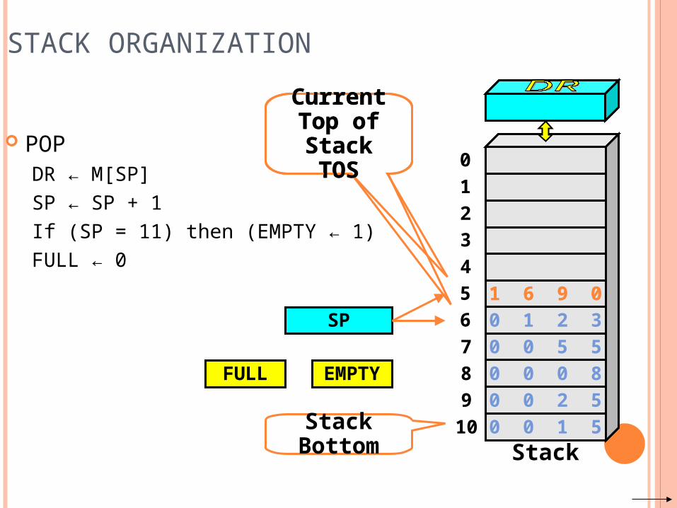
STACK ORGANIZATION
POPDR ← M[SP]SP ← SP + 1If (SP = 11) then (EMPTY ← 1)FULL ← 0
SP
Stack Bottom
CurrentTop of Stack
TOS 01234
78910
56
Stack
0 0 5 50 0 0 80 0 2 50 0 1 5
0 1 2 3
FULL EMPTY
1 6 9 01 6 9 0
CurrentTop of Stack
TOS
012
102
202201200
100101
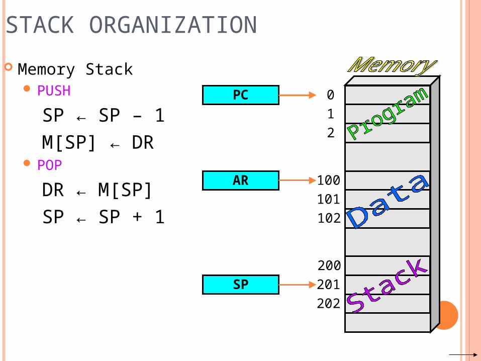
STACK ORGANIZATION Memory Stack
PUSHSP ← SP – 1M[SP] ← DR
POPDR ← M[SP]SP ← SP + 1
PC
AR
SP
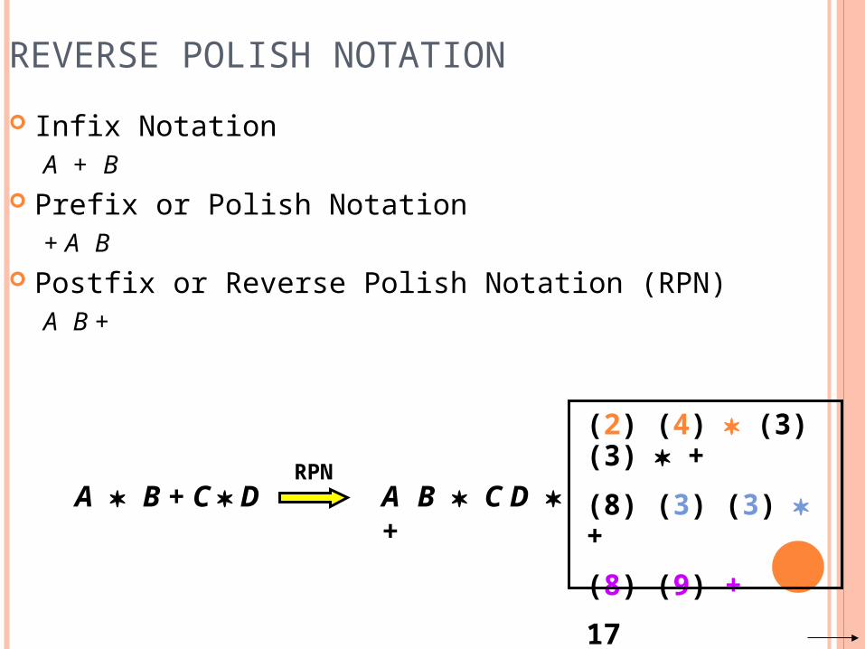
REVERSE POLISH NOTATION Infix Notation
A + B Prefix or Polish Notation
+ A B Postfix or Reverse Polish Notation (RPN)
A B +
A B + C D A B C D +RPN
(2) (4) (3) (3) +(8) (3) (3) +(8) (9) +17
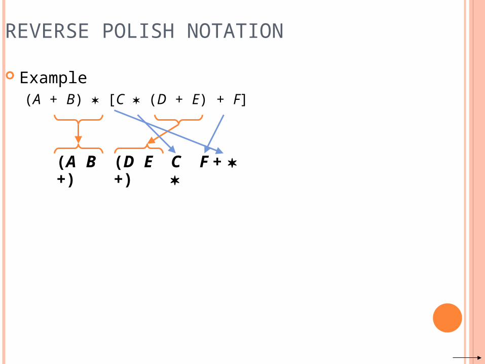
REVERSE POLISH NOTATION Example
(A + B) [C (D + E) + F]
(A B +) (D E +) C F +
REVERSE POLISH NOTATION
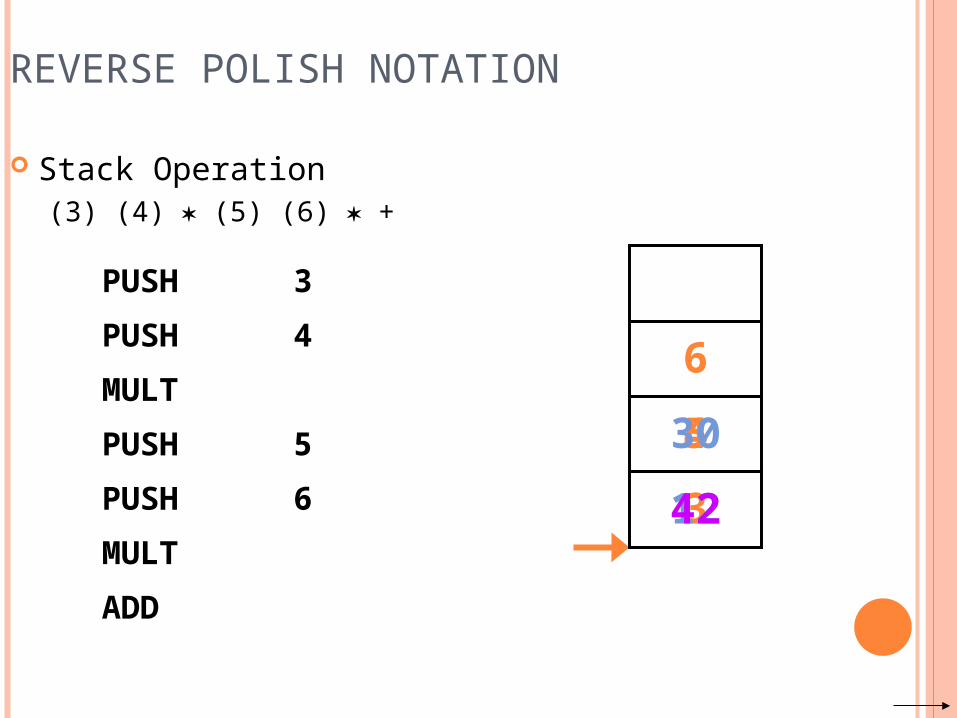
Stack Operation(3) (4) (5) (6) +
PUSH 3PUSH 4MULTPUSH 5PUSH 6MULTADD
3
4
12
5
6
30
42
ADDITIONAL INSTRUCTIONS
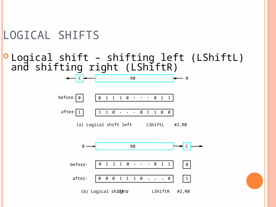
LOGICAL SHIFTS Logical shift – shifting left (LShiftL) and
shifting right (LShiftR)
CR00
before:
after:
0
1
0 0 01 1 1 . . . 11
0 0 1 1 1 000
(b) Logical shift right LShiftR #2,R0
(a) Logical shift left LShiftL #2,R0
C R0 0
before:
after:
0
1
0 0 01 1 1 . . . 11
1 10 . . . 00101
. . .
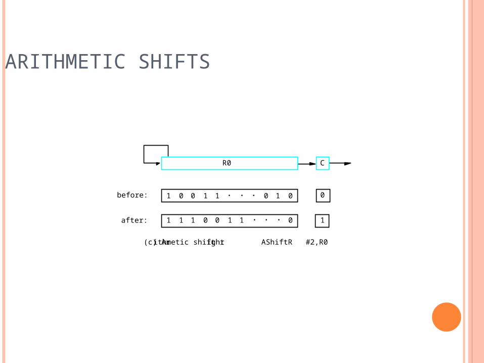
ARITHMETIC SHIFTS
C
before:
after:
0
1
1 1 00 0 1 . . . 01
1 1 0 0 1 011
(c) Arithmetic shift right AShiftR #2,R0
R0
. . .
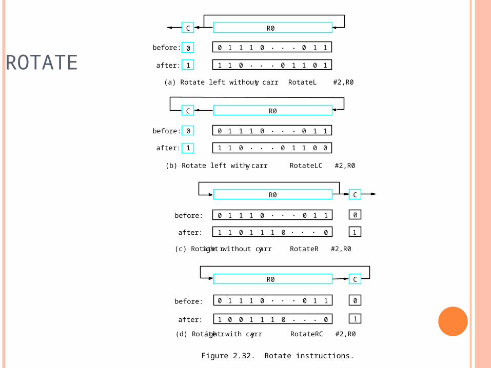
ROTATE
Figure 2.32. Rotate instructions.
CR0
before:
after:
0
1
0 0 01 1 1 . . . 11
1 0 1 1 1 001
(c) Rotate right without carry RotateR #2,R0
(a) Rotate left without carry RotateL #2,R0
C R0
before:
after:
0
1
0 0 01 1 1 . . . 11
1 10 . . . 10101
C
before:
after:
0
1
0 0 01 1 1 . . . 11
1 0 1 1 1 000
(d) Rotate right with carry RotateRC #2,R0
R0
. . .
. . .
(b) Rotate left with carry RotateLC #2,R0
C R0
before:
after:
0
1
0 0 01 1 1 . . . 11
1 10 . . . 00101
MULTIPLICATION AND DIVISION Not very popular (especially division) Multiply Ri, Rj
Rj ← [Ri] х [Rj] 2n-bit product case: high-order half in R(j+1) Divide Ri, Rj
Rj ← [Ri] / [Rj]Quotient is in Rj, remainder may be placed in R(j+1)
ENCODING OF MACHINE
INSTRUCTIONS
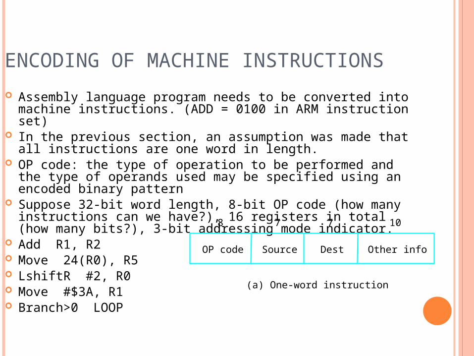
ENCODING OF MACHINE INSTRUCTIONS Assembly language program needs to be converted into
machine instructions. (ADD = 0100 in ARM instruction set) In the previous section, an assumption was made that all
instructions are one word in length. OP code: the type of operation to be performed and the type
of operands used may be specified using an encoded binary pattern
Suppose 32-bit word length, 8-bit OP code (how many instructions can we have?), 16 registers in total (how many bits?), 3-bit addressing mode indicator.
Add R1, R2 Move 24(R0), R5 LshiftR #2, R0 Move #$3A, R1 Branch>0 LOOP
OP code Source Dest Other info
8 7 7 10
(a) One-word instruction
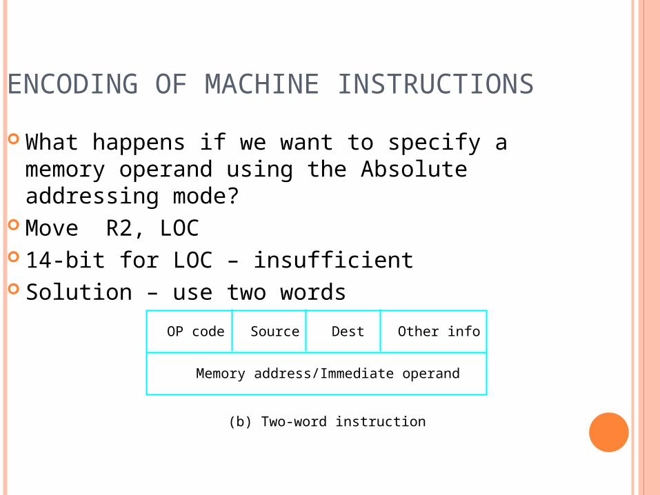
ENCODING OF MACHINE INSTRUCTIONS What happens if we want to specify a memory
operand using the Absolute addressing mode? Move R2, LOC 14-bit for LOC – insufficient Solution – use two words
(b) Two-word instruction
Memory address/Immediate operand
OP code Source Dest Other info
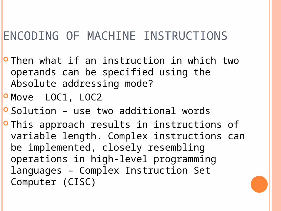
ENCODING OF MACHINE INSTRUCTIONS Then what if an instruction in which two
operands can be specified using the Absolute addressing mode?
Move LOC1, LOC2 Solution – use two additional words This approach results in instructions of
variable length. Complex instructions can be implemented, closely resembling operations in high-level programming languages – Complex Instruction Set Computer (CISC)
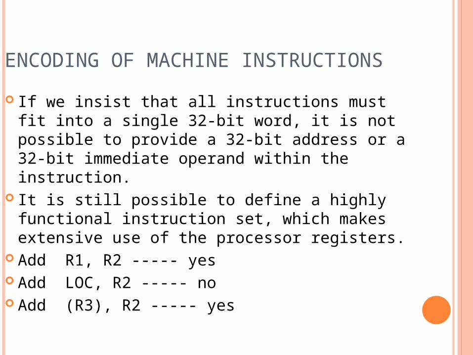
ENCODING OF MACHINE INSTRUCTIONS If we insist that all instructions must fit into a
single 32-bit word, it is not possible to provide a 32-bit address or a 32-bit immediate operand within the instruction.
It is still possible to define a highly functional instruction set, which makes extensive use of the processor registers.
Add R1, R2 ----- yes Add LOC, R2 ----- no Add (R3), R2 ----- yes