basic study on tactile sensor by using magnetic suspension
TRANSCRIPT
Year 2007
Master Thesis
Basic study on tactile sensor by using magnetic suspension
Wakayama University Graduate School of Systems Engineering
Opto Micro Systems Cluster
Student ID: 60070066
Name: TUTY RAHIZA BINTI SAJAT
Submit on 8th February 2008

Basic study on tactile sensor by using magnetic suspension
Tuty Rahiza Binti Sajat
Wakayama University Graduate School of Systems Engineering
Opto Micro Sytems Cluster
Abstract
In late years, a study on robotic engineering field is rapid especially in development of
humanoid robot. A robot with the controlling of grasp force ability is desirable. Thus, tactile
sensor that could detect slipping force is needed and enables in application for the robotic
fingertips. In this study, a novel tactile sensor utilizing magnetic attraction force that
consequently working between the permanent magnet and magnetic material was proposed.
The possibility of magnetic attraction force to perform as magnetic suspension for
measuring the slipping force was investigated. The characteristic of permanent magnet was
used in realizing a simple structure that enables a freely supportive structure.
Firstly, the sensing principle was studied by finite element method (FEM). The analytical
model consist of a full-typed Ni-Fe pole that embedded in a plastic ball with the size of
diameter 4mm. A permanent magnet soleplate was placed at gap 0.4mm under the plastic
ball. The simulation result showed a good linearity at the range of ±40°. The linear curve
could be signified by restorative force expression, . Consequently, the author concludes the performance of magnetic suspension was confirmed. In other respects, the
sensitivity characteristic was also inspected by observing the shifting of magnetic field
against the rotation angle. 2mT/deg of sensitivity was obtained when on Ni-Fe soleplate at
intervals of ±1mm. The sensitivity decreased for permanent magnet soleplate to 0.3mT/deg
at intervals of ±0.5mm. Rotation angle, was needed to obtain of the aim
sensitivity. As the enters the operation range it can be said that the aim sensitivity can be achieved.
A prototype model was fabricated to demonstrate proposed sensing principle
experimentally. The experiment results indicate that the magnetic suspension performed
well though the order of restorative force is different to analytical result. Furthermore, the
Giant Magneto Resistant (GMR) sensor was used to investigate the magnetic field
distribution. The experiment result corresponded well to the analytical one. From the
above-mentioned result, it is contemplated that the realization of magnetic –typed tactile
sensor is possible.

Contents Chapter 1 Introduction 1
1.1 Background of the study 1
1.1.1 Human sense of touch 1
1.1.2 Tactile sensor 1
1.2 Objective of this study 2
Chapter 2 Principle and design concept of tactile sensor 4
2.1 Principle of tactile sensor 4
2.1.2 Selection of sensing principle 4
2.1.2 Magnetic principles 4
2.2 Design concept for magnetic type 6
Chapter 3 Analytical simulation 8
3.1 Initial model 8
3.1.1 Reviews on principle 8
3.1.2 Sensitivity characteristic 9
3.2 Secondary model 9
3.2.1 Reviews on principle 9
3.2.2 Magnetic field distribution 11
3.2.3 Sensitivity characteristic 12
3.2.4 Alignment of GMR sensor 13
Chapter 4 Experiment 14
4.1 Fabrication of prototype model 14
4.2 Torque characteristic measurement 14
4.3 Magnetic characteristic of GMR sensor 15
4.4 Magnetic field distribution 17
Chapter 5 Conclusion 18
Acknowledgement 19
References 19
Achievements 19
Appendix 20

1
Chapter 1 Introduction
1.1 Background of the study
1.1.1 Human sense of touch
Human being has 5 senses which are
sight, hearing, touch, smell and taste. Each
of these senses has their own receptor to
detect and make movement. If a robot with
a sense like human being can come out, the
realization of superior humanoid robot to
work together with human being will not be
just a dream in future.
In late years, a study on robotic
engineering field is rapid especially in
development of humanoid robot in
contributing spectacularly to the
industrialization and modernization
worldwide. Many researchers are trying to
develop robots which can help human.
Nowadays, vision sensor, hearing sensor,
and tactile sensor are being developed for
robots. However, the development of tactile
sensor is late, compared with vision sensor
and hearing sensor. The reason of this delay
can be said that the structure of the human
sense of touch has begun to be elucidated
comparatively recent.
The following matters explain how a
human being feels the sense of touch.
Stimulation information from the outside is
received by the receptors that embedded in
skin. The information is sent to brain and
being recognized as the sense of touch.
Human being has several actions handled
unconsciously. One of those is “control of
grasping force action”. For example, human
being can hold a cup fills with water
without crushing or dropping it. In fact, the
cup is being slip in pettiness in the edge of
finger. Human being detects it
unconsciously and automatically adjusts
the grasp force applied to prevent the cup
from falling. In this study, this kind of
human ability is called “the minimal grasp
force” and it is a huge task to keep such
sense to a robot hand.
1.1.2 Tactile Sensor
Tactile sensor became the subject of
intense research and development during
the 1990s. Tactile sensor is a device, which
measures the parameter of a contact
between the sensor and an object. An
excellent tactile sensor is needed in the
fields of robotics industry. There is a range
of applications throughout industry for
tactile sensor, such as vehicle’s anti-lock
braking systems (ABS), traction control,
robotic grippers and object handling.
Furthermore, in recent years tactile sensor
is not only required in robotics industry, but
also in the fields of medical treatment and
welfare. In this area, application to the
inspection diagnosis device as sensing
technology is expected to treat a flexible
subject.
Table 1.1 shows the typical
classification of tactile sense. Pressure and
slipping force are the main parameters that
being measured by tactile sensor. Up to now,
there has been extensive research on tactile

2
sensors, with sensing principles based on
Table 1.1 Classifications of tactile sense(3)
piezoresistive, capacitive, piezoelectric
vibration, and light. Dzung et al (1) reported
a 3-Degree of Freedom (DOF) soft-contact
tactile sensor utilizing piezoresistive effect.
Motoo Kohei et al (2) developed a
piezoelectric vibration-type tactile sensor
using elasticity and viscosity change of
sensor structure. These devices detect the
contact force between the sensor and an
object. Tactile sensors with distributed
pressure transducers, have advantages in
acquiring surface or the shape’s
information of the objects. However, little
attempt has been made to feature their
functional merits which are still not clear.
In addition, they are not equipped with slip
sensing function, which is indispensable to
dynamic sensing.
On the other hand, a tactile sensor
that utilizes light also has been developed.
Since a tactile sensor based on this
principle requires a charge-coupled device
(CCD) camera and image data processing,
miniaturization is difficult and the cost is
high. At present, conventional tactile
sensors are not used for humanoid robots at
a practical level.
A tactile sensor with the ability to
measure slipping force is important to
make dexterous grasping operations of
robot hand. If a robot gets possible to
recognize sliding, it is believed that the
minimal grasp force is enabled by feeding
back the sliding information to grasp. Then,
it is possible to let a robot hand to treat the
object that is easy to slip or breakable .
1.2 Objective of this study
The author focus on the idea to enable
robot hands to have grasp force control
ability, which could measure not only
pressure but also slipping force. The
following things are the conditions
demanded for a tactile sensor (3).
1. Simple structure
2. Small size and low weight
Detection contents Purpose of applications
Pressure Grasp force
Pressure of the finger tip
Pressure distribution
Grasp force control
Measuring the elastic
characteristic of the object
Slipping Displacement and rotation of object in the
vertical direction in grasp side
Decision and adjustment of the
grasp force targeted value
Prevention of the sliding
Measurement of the surface
characteristic

3
3. Posses high reliability and
sensitivity
4. Densification is possible
In the future, the author concerns to
have an array system for tactile sensor.
Therefore, simple structure and small size
are important keys for the realization. At
present, each sensor element of pressure
distribute-typed tactile sensor
comparatively has complex structure. In
this approach, overall structure of tactile
sensors becomes complicated and difficult
in developing sensor array systems.
In this study, a novel sensing method
using magnetic suspension, which enables
simple structure and has advantages in
self-align suspension was proposed. As a
new method for driving the sensor element,
the author investigated the possibility of
using a magnetic attractive force between a
permanent magnet and magnetic material.
The author targets to develop a tactile
sensor that has sensitivity to measure 1µN
of slipping force.
4
Chapter 2 Principle and design concept of tactile sensor
2.1 Principle of tactile sensor
2.1.1 Selection of sensing principle
Many different principles have been
researched and developed. Table 2.1 shows
the comparative of sensing principles for
tactile sensors. Tactile sensor based-on
piezoresistive is excellent in properties of
DOF although a suspension is needed to
hold sensor elements but their performance
deteriorates in the wet environment.
Capacitive-typed tactile sensor also has
similar advantages to piezoresistive-typed
in degree-of-freedom. However,
miniaturization is difficult because high
precision of suspension structure is
necessary. Furthermore, they have
disadvantage that is easy to be affected by
the humidity. On the other hand, because
inductive-type uses a coil for sensing, the
simplification structure is not easy.
In consideration of possibility to
miniaturize tactile sensor, piezoresistive
detection and magnetic type are two
principles, which seems to be the most
promising. In miniaturization, structure
simplicity is required and we develop a
free-suspension structure to satisfy the
requirement. Compared to piezoresistive
principles, magnetic-type is appropriate for
this structure due to the attractive force of
permanent magnet and promising
attractive prospects in future.
In this study, the author take
particular note of attractive force that
consistently working between permanent
magnet and magnetic material. However,
the idea of using magnetic force in driving
sensor element for tactile sensor is still new
and there are some issues to be cleared
such as the possibility and device
properties. By utilizing the magnetic force
characteristic, a tactile sensor that has
advantage in self-sensing function is
proposed.
Humanoid robots is assumed as
indispensable thing for human life in the
future. A robot is used not only in the
production factory but also at the house in
helping chores. In this case, it is essential
for those tactile sensors having
environmental robustness so that they
could perform housework in wet
environment such as kitchen.
2.1.2 Magnetic Principles
Fig.2.1 shows the principle of
magnetic-typed tactile sensors. The initial
structure of tactile sensor consists of a
magnetic material covered with plastic ball
as the sensor element and a permanent
magnet is placed right under the ball (Fig.
2.1.a). Magnetic sensor is also placed next
to permanent magnet to detect the changes
of magnetic field.
In the static mode, as mentioned in
section 2.1.1, attractive force is consistently
working between permanent magnet and
magnetic material. Magnetic field is
5
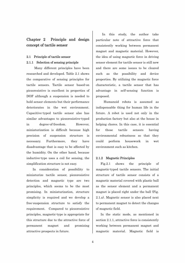
symmetric around the permanent magnet.
Table 2.1 Comparative chart of sensing principles
○:Excellent △:Good ×:Bad
When the plastic ball received
stimulation information from the outside,
the coordinate of magnetic pole will shift to
the opposite axis due to the rotation of
plastic ball and causes the changes of
magnetic field distribution (Fig. 2.1.b). At
this time, restorative force, F1 will be
generated on the magnet material and
make it get back to the original position.
This can be characterized as follows.
(1)
Where the k is the spring coefficient and
the θ is the rotate angle. In this study, the
author considered spring coefficient as
suspension and restorative force as
measured slipping force. The magnetic
field’s difference is transformed into an
electrical signal output.
(a) At the static mode
(b)When externally-applied force
Principle DOF Robustness Structure Suspension
Piezoresistive 1 or 3 △ ○ Need
Capacitive 3 × △ Need
Inductive 1 ○ × Need
Magnetic 2 ○ ○ Not need
roller guide restorative force
sensor 1 sensor 2
permanent magnet
magneticmaterial
plastic ball Fx
rotation
roller guideattractive force
sensor 1 sensor 2
permanent magnet
magnetic material
plastic ball

6
Fig. 2.1 Magnetically driven tactile sensor
2.2 Design concept for magnetic type
In designing a tactile sensor, simplicity
in structure is imperative in order to
construct sensors’ array system and
miniaturization. In other respects, the
author is focusing in the measurement of
slipping force in this study, therefore
suspension became an important factor.
The piezoresistive-typed tactile sensor (1)
consist a frame to hold the sensor element,
which is centrally placed. This frame
performs a function as suspension and
when force is given to the suspension,
spring force will be generated. The
precision of suspension part is highly
required because it is deeply linked to
sensor sensitivity and structure.
Conventional tactile sensors (1) have a
frame that causes the overall structure to
be complex, which limited the possibility for
miniaturization. As a solution, the author
proposed a novel structure of tactile sensor
with no frame for suspension that make the
structure more simple with self-suspension
function as the merit.
In order to realize this structure, the
author suggests a tactile sensor that
utilizes magnetic suspension, which is
performed by permanent magnet. Five
models are proposed as sensor structure to
study the possibility of suggested
magnetically driven mechanism. As shown
in Fig.2.2, a tactile sensor, which consist a
diameter 5.5mm magnetic material as
sensor element covered with plastic ball to
prevent oxidization is developed. A pole
type permanent magnet:
is placed right under the ball. The size is
decided on the easy-to-fabricate reason.
This model is set as the initial model and
promising a high magnetic attractive force
property due to the small surface in contact
between the magnetic material and
permanent magnet.
Another four models also suggested
considering the performance of permanent
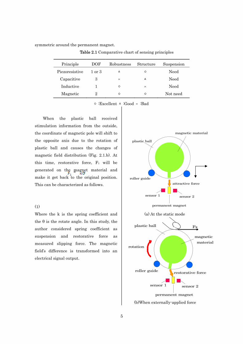
magnet when set as soleplate (Fig. 2.3). Fig.
2.3 (a) and (b) have a half pole and full pole,
respectively. The following two structures
were used to get the optimized structure. In
structure 1, the permanent magnet
soleplate and the Ni-Fe pole was used.
Fig. 2.2 Initial model
(a) (b)
7
Fig.2.3 Secondary model (a) Half-typed pole (b)Full-typed pole
In structure 2, the vise versa was used.
These models promising the enhancement
of magnetic adsorption rate between the
soleplate and the pole. Further study on
each models will be discuss in chapter 3
and define as the secondary model.
There is a possibility that a tactile
sensor will slip off when a force that bigger
than slipping forces is given to it. As a
practical matter, a roller guide is required
to prevent the tactile sensor from moving
further than the operation range. Even now,
e.g. a devise to increase the fractional force
is done by arrange hard rubber around the
sensor.

8
Chapter 3 Analytical simulation
3.1 Initial model
3.1.1 Reviews on principle
Finite Element Method (FEM) was
used to analyze the proposed sensing
concept. As mentioned in section 2.2.1, this
tactile sensor utilizes the magnetic
attraction force between the permanent
magnet and ferromagnetic material. In
general, magnetic attractive force, F2 is
denoted as follows if magnetic field, H from
magnet is enough to saturate the magnetic
material.
(2)
Where, Ms is the saturation induction of
ferromagnetic material.
Fe was chose as the magnetic material
because Fe has high saturation magnetic
flux density, relatively high permeability
and easy to work. Fig.2.2 shows the initial
analytical model. Analysis condition are
characterized as follows.
Permeability of Fe: 300
Permeability of air: 1
Permeability of permanent magnet: 1
Saturation flux density: 2.2T
Gap between Fe and permanent magnet:
0.8mm
Size of permanent magnet:
Firstly, the prerequisite value of coercive
force is required in order to generate 1µN of
restorative force of magnetic material when
tactile sensor changed at a minute rotation
angle. The coercive force of permanent
magnet is set up as parameter and relation
with the restorative force was studied. In
this simulation, the B-H curve was
approximated by linear curve with the
permeability of permanent magnet as 1 and
the relation can be express by follows,
. The operating characteristic is showed in Fig.3.1. As the author analyzed
shape by fixation, the magnetic flux density
is in proportion to coercive force. The
intensity of permanent magnet is related to
coercive force and shape.
Fig.3.2 shows the simulation results.
From the results, when minute rotation
angle is set to 1 degree, the author
concluded that 200kA/m of coercive force is
needed to generate 1µN of restorative force.
This value is used in all the analysis.
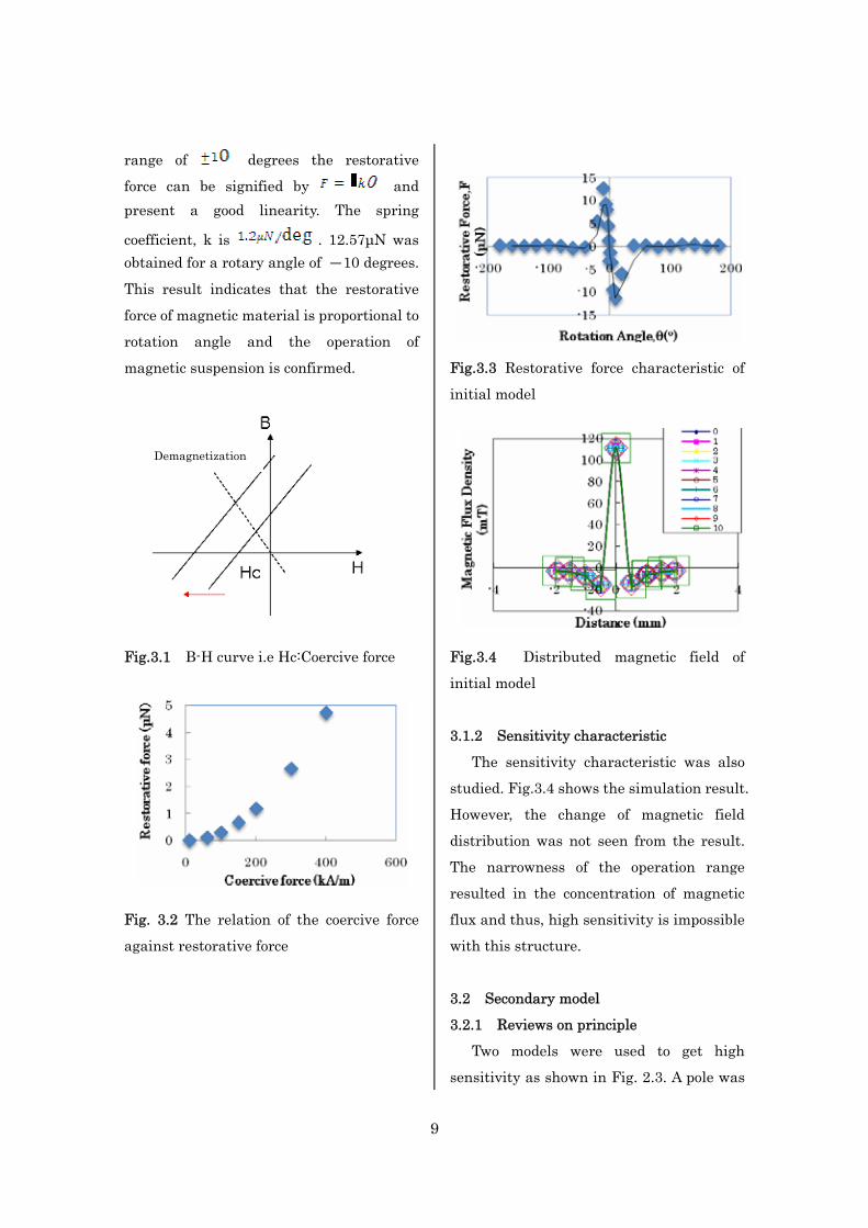
The restorative force characteristic is
investigated to confirm the sensing
principle with this result. The restorative
force of magnetic material on the rotation
angle was investigated. The range was
degrees. As shown in Fig. 3.3, at the
9
range of degrees the restorative
force can be signified by and present a good linearity. The spring
coefficient, k is . 12.57µN was obtained for a rotary angle of -10 degrees.
This result indicates that the restorative
force of magnetic material is proportional to
rotation angle and the operation of
magnetic suspension is confirmed.
Fig.3.1 B-H curve i.e Hc:Coercive force
Fig. 3.2 The relation of the coercive force
against restorative force
Fig.3.3 Restorative force characteristic of
initial model
Fig.3.4 Distributed magnetic field of
initial model
3.1.2 Sensitivity characteristic
The sensitivity characteristic was also
studied. Fig.3.4 shows the simulation result.
However, the change of magnetic field
distribution was not seen from the result.
The narrowness of the operation range
resulted in the concentration of magnetic
flux and thus, high sensitivity is impossible
with this structure.
3.2 Secondary model
3.2.1 Reviews on principle
Two models were used to get high
sensitivity as shown in Fig. 2.3. A pole was
Demagnetization

10
embedded into plastic ball and a plate type
permanent magnet was used instead of
permanent magnet pole. The size of plate
and plastic ball are, and 4mm, respectively.
The gap between plastic ball and plate is
0.4mm. The former model has a half-sized
pole and the latter model
has a sized pole. The gap
between plastic ball and permanent magnet
was changed from original 0.8 mm to 0.4
mm. Compared to the initial model, a
smaller size of tactile sensor is suggested to
increase the adsorption rate of the
magnetic field. A Ni-Fe alloyed metal was
chose because has higher permeability in
substitution for Fe. High permeability
material is desirable to enhance the
magnetic attractive force in relatively low
field.
In these models, magnetic flux from
permanent magnet is supposed does not
concentrate to soft magnetic material. The
following two conditions was used in
analysis. Analytical conditions were as
mentioned below.
Permeability of Ni-Fe: 1000
Permeability of permanent magnet: 1
Permeability of air : 1
Coercive force of permanent
magnet :200kA/m
Condition 1:
Permanent magnet as soleplate
Ni-Fe as soleplate
Condition 2:
Permanent magnet as soleplate
Ni-Fe as pole
The restorative force characteristic was
studied on the secondary models. The
contact between the rotational angle and
restorative force was examined.
was set as rotation angle of the plastic ball. From the results as shown
in fig.3.5 indicates that in the both
condition can obtained a good linearity at
the degrees of operation range. Comparatively larger operation range was
obtained than initial model. The linear
curve could be signified by restorative force
equation as mentioned in chapter 2 and the
author conclude that magnetic suspension
was performed well.
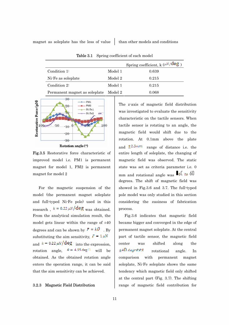
Table 3.1 shows the spring coefficient for
each model and conditions, respectively.
Model 1 is the half-typed pole model and
model 2 is the full-typed pole model. This
table indicates that model 1 has bigger
spring coefficient value in comparison with
model 2. A small spring coefficient is
preferable for tactile sensors to perform a
minute force in operation. In this case,
half-typed pole model with permanent
11
magnet as soleplate has the less of value than other models and conditions
Table 3.1 Spring coefficient of each model
Fig.3.5 Restorative force characteristic of
improved model i.e. PM1 is permanent
magnet for model 1, PM2 is permanent
magnet for model 2
For the magnetic suspension of the
model (the permanent magnet soleplate
and full-typed Ni-Fe pole) used in this
research , was obtained. From the analytical simulation result, the
model gets linear within the range of ±40
degrees and can be shown by . By substituting the aim sensitivity,
and into the expression, rotation angle, will be obtained. As the obtained rotation angle
enters the operation range, it can be said
that the aim sensitivity can be achieved.
3.2.3 Magnetic Field Distribution
The z-axis of magnetic field distribution
was investigated to evaluate the sensitivity
characteristic on the tactile sensors. When
tactile sensor is rotating to an angle, the
magnetic field would shift due to the
rotation. At 0.1mm above the plate
and range of distance i.e. the entire length of soleplate, the changing of
magnetic field was observed. The static
state was set as criteria parameter i.e. 0
mm and rotational angle was degrees. The shift of magnetic field was
showed in Fig.3.6 and 3.7. The full-typed
pole model was only studied in this section
considering the easiness of fabrication
process.
Fig.3.6 indicates that magnetic field
became bigger and converged in the edge of
permanent magnet soleplate. At the central
part of tactile sensor, the magnetic field
center was shifted along the
rotational angle. In comparison with permanent magnet
soleplate, Ni-Fe soleplate shows the same
tendency which magnetic field only shifted
at the central part (Fig. 3.7). The shifting
range of magnetic field contribution for
Spring coefficient, k ( ) Model 1 0.639 Condition 1:
Ni-Fe as soleplate Model 2 0.215
Model 1 0.215 Condition 2:
Permanent magnet as soleplate Model 2 0.068

12
Ni-Fe soleplate is larger compared with
permanent magnet soleplate.
Fig.3.6 Magnetic field distribution of
permanent magnet soleplate
Fig.3.7 Magnetic field distribution of Ni-Fe
soleplate
From this result, the author concludes
that improved model indicates better
magnetic field contribution comparing to
initial model. Furthermore, the magnetic
field was altered against the rotation angle
and sensitivity characteristic can be
evaluated.
3.2.4 Sensitivity characteristic
The sensitivity characteristic on
improved model is evaluated using the
analytical results from section 3.1.4. In this
study, the author intends to detect flux
variation with a Hall sensor. The z-axis of
magnetic field distribution was studied
because Hall sensor could only detect
unidirectional magnetic field. Fig. 3.8
shows the schematic diagram of the
evaluation method and the explanation was
as follows.
The author assumed that to arrange
Hall sensor in two places i.e. sensor 1 and
sensor 2. The differential of magnetic field
is calculated in this interval when the
tactile sensors were turned by 10 degrees
from degrees. Sensitivity is calculated from the linear part of graph
from Fig. 3.9.
When permanent magnet is set as
soleplate, of sensitivity at a
range of distance from standard state was obtained. On the other hand, the
sensitivity is for Ni-Fe
soleplate at the range of distance. From this result, Ni-Fe soleplate indicates
higher sensitivity in comparison with the
permanent magnet soleplate.
The author adopted Hall sensor as
magnetic sensor for a gap 0.8 mm in the
first place for initial model. Hall sensor has
higher sensitivity compared to others
magnetic sensor in measuring the magnetic
fields’ differences. However, the author find
difficulty to obtain high sensitivity for

13
initial model as discussed in section 3.1.2
and, thus to narrow the gap from 0.4mm to
0.8mm in enhancement the adsorption rate
of the magnetic field.
Though superb sensitivity could be
gained with Hall sensor, the author
understood that it is difficult to realize a
Hall sensor for gap 0.4mm. Therefore,
Giant Magneto Resistance (GMR) sensor,
which is thinner than Hall sensor as
substitute was proposed.
0.1mm
interval
sensor 1 sensor 2
Fig.3.8 Schematic diagram of evaluation
method
Fig.3.9 Sensitivity characteristic of
improved model
3.2.5 Alignment of GMR sensor
Relative to Hall sensor, which only
detects unidirectional magnetic field, a
GMR sensor responds to all direction of the
magnetic field. Therefore, the alignment of
GMR sensor has to be studied In this case,
the author study only for permanent
magnet soleplate based on inspecting
improved model by experiment.
GMR sensor assume to place at 0.1mm
above permanent magnet soleplate. The
magnetic field distribution was observed
from the center point by every distance due to the rotation. The analyze
results was showed in Fig. 3.10.
From this figure, the highest magnetic
sensitivity was obtained at distance from the center point. The
sensitivity is . GMR sensor should be aligning at this point in order to
detect the shift of magnetic field. The same
sensitivity was provided in smaller space in
comparison with Hall sensor.
Fig.3.10 GMR sensor alignment

14
Chapter 4 Experiment
4.1 Fabrication of prototype model
A prototype model was fabricated to
demonstrate the proposed principle by
experiment. The improved model (b) as
mentioned in chapter 3 was fabricated. A
cyclic ball with the size of diameter 5.5 mm
was drilled through its center. Drilling was
done by using laser cutter and the core
diameter is 1.2 mm. Fe pole: was
embedded to the core. of
permanent magnet plate was placed right
under the cyclic ball. A blue plastic as the
roller guide was covered the cyclic ball.
Fig.4.1.a shows the naked structure of the
fabricated sample and Fig. 4.1.b shows the
completed prototype model.
4.2 Torque characteristic measurement
The contact between rotation angle and
the torque force was investigated to study
the operation of the magnetic suspension .
Voice coil motor (VCM) is a particular type
of motor that is designed to provide linear
motion. The VCM that being used in this
experiment generates of force
against applied current (4). Model in Fig.4.1.b was used in the experiment.
A bend string attached from the free
edge of Fe pole to VCM stage as shown in
Fig. 4.2. Then, a position of VCM was fixed
and set the position as default. The string
was strained by moving the movable stage
to a distance. The movement changed the
angle of tactile sensor. The current value
that needed till displacement return to the
default was measured. Torque force was
calculated from the necessary electric
current. Gauss meter measured the
coercive force of permanent magnet. The
value is equivalent as used in the
simulation that is 216kA/m.
Fig.4.1.a Fabricated prototype model
Fig.4.1.b Fabricated prototype model with
blue plastic cover as the roller guide
Sample VCM
20Ω
CurrentPowerSupply
String
Movablestage
Fig.4.2 Schematic diagram of

15
experimental setup

16
In the initial experiment, a linear curve
with nearly 20 degrees slipped off from the
origin was obtained. The causation of this
error is the misalignment of experiment
device. The string that linked to the VCM
has to be parallel but the experiment device
has an angle from the beginning. The
experiment device was improved by
designing a better device and performed
new experiment. In the retrial experiment, a linear curve
via the origin in the operation range of 0 to
10 degrees was obtained as shown in Fig.
4.3. From this result, the linear curve could
be signify by restorative force equation,
and the spring coefficient, k is . The objective of this
experiment was to observe the performance
of the magnetic suspension and the
tendency. The existence of k value from
linearity in the experiment results shows
that magnetic suspension is confirmed
experimentally. Rotation angle, was derived from the following equation.
(4)
Where, x denotes the displacement and r
denotes the radius of the sphere.
Experiment result is corresponded well
with the analytical one, though the order of
restorative force is different. The reason
might be the size difference between the
analytical model and the fabricated
prototype. The diameter of the pole in
analytical and fabricated prototype was
respectively and . The fabricated model has relatively larger
surface area, thus bigger adsorption of the
magnetic field was generated towards the
permanent magnet soleplate.
Fig.4.3 Torque characteristic by experiment
4.3 Magnetic characteristic of GMR sensor
As discussed before in section 3.2.4, a
thin magnetic sensor is required. Therefore,
the GMR sensor that composed by thin
magnetic multilayer was adopted (Fig.4.4).
GMR sensor used in this study was
provided by Panasonic Electronic Device Co.
Japan. They fabricated a meander shape
GMR element. The size of line width, entire
length, and width are 10 µm, 140 µm, and
115 µm, respectively (Fig.4.5). At first, the
magnetic characteristic of this sensor was
evaluated by experiment because the
properties are not clear yet. The
characteristic was measured using the
following steps.
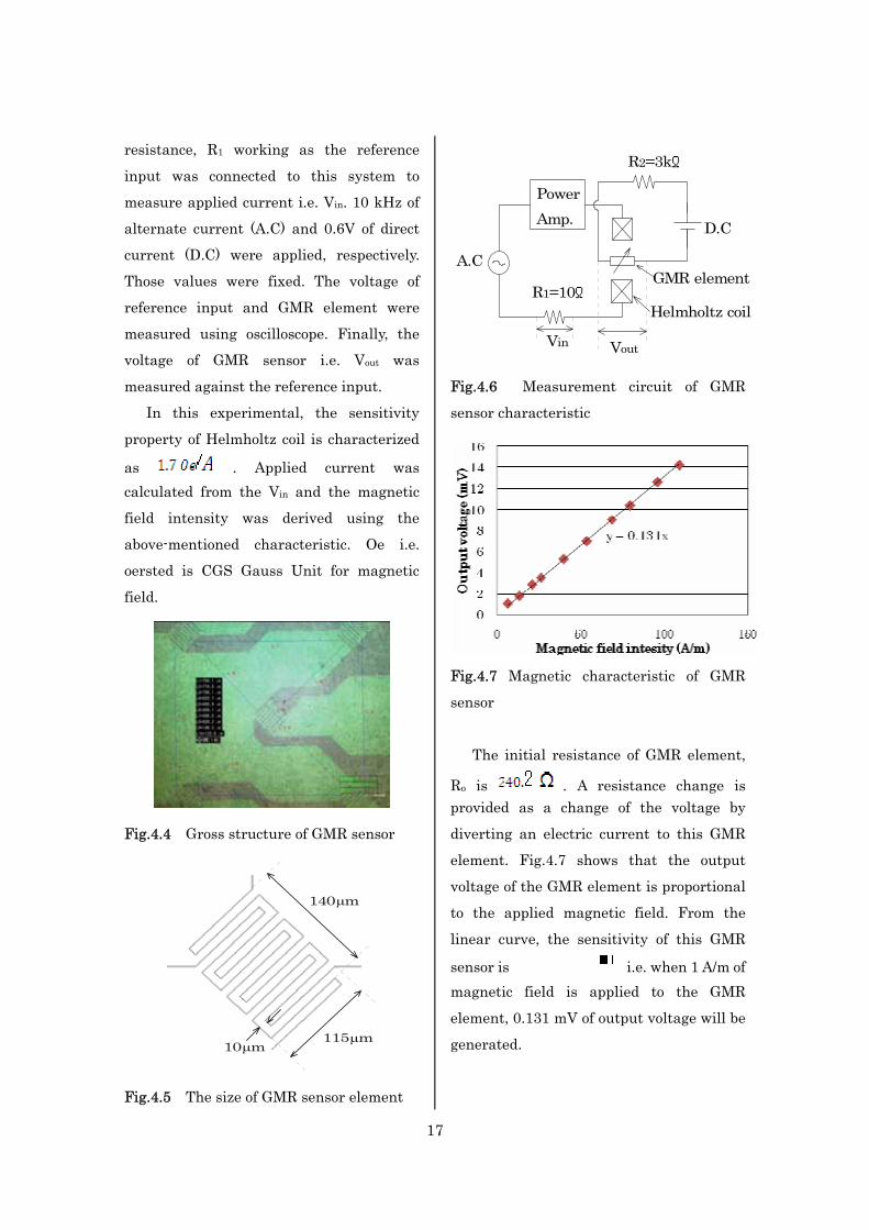
First, the measurement circuit was set
as shown in Fig. 4.6. The magnetic field
intensity was controlled using a
measurement system consisting a function
generator and Helmholtz coil. A fixed
17
resistance, R1 working as the reference
input was connected to this system to
measure applied current i.e. Vin. 10 kHz of
alternate current (A.C) and 0.6V of direct
current (D.C) were applied, respectively.
Those values were fixed. The voltage of
reference input and GMR element were
measured using oscilloscope. Finally, the
voltage of GMR sensor i.e. Vout was
measured against the reference input.
In this experimental, the sensitivity
property of Helmholtz coil is characterized
as . Applied current was calculated from the Vin and the magnetic
field intensity was derived using the
above-mentioned characteristic. Oe i.e.
oersted is CGS Gauss Unit for magnetic
field.
Fig.4.4 Gross structure of GMR sensor
140µm
115µm10µm
Fig.4.5 The size of GMR sensor element
A.C
R1=10ΩGMR element
D.C
R2=3kΩ
Helmholtz coil
PowerAmp.
Vin Vout
Fig.4.6 Measurement circuit of GMR
sensor characteristic
Fig.4.7 Magnetic characteristic of GMR
sensor
The initial resistance of GMR element,
Ro is . A resistance change is provided as a change of the voltage by
diverting an electric current to this GMR
element. Fig.4.7 shows that the output
voltage of the GMR element is proportional
to the applied magnetic field. From the
linear curve, the sensitivity of this GMR
sensor is i.e. when 1 A/m of magnetic field is applied to the GMR
element, 0.131 mV of output voltage will be
generated.
18
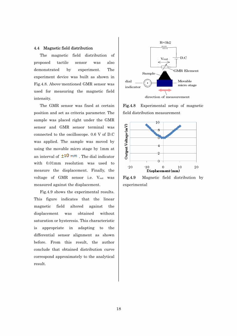
4.4 Magnetic field distribution
The magnetic field distribution of
proposed tactile sensor was also
demonstrated by experiment. The
experiment device was built as shown in
Fig.4.8. Above-mentioned GMR sensor was
used for measuring the magnetic field
intensity.
The GMR sensor was fixed at certain
position and set as criteria parameter. The
sample was placed right under the GMR
sensor and GMR sensor terminal was
connected to the oscilloscope. 0.6 V of D.C
was applied. The sample was moved by
using the movable micro stage by 1mm at
an interval of . The dial indicator with 0.01mm resolution was used to
measure the displacement. Finally, the
voltage of GMR sensor i.e. Vout was
measured against the displacement.
Fig.4.9 shows the experimental results.
This figure indicates that the linear
magnetic field altered against the
displacement was obtained without
saturation or hysteresis. This characteristic
is appropriate in adapting to the
differential sensor alignment as shown
before. From this result, the author
conclude that obtained distribution curve
correspond approximately to the analytical
result.
D.C
R=3kΩ
SampleGMR Element
direction of measurement
Movablemicro stage
dial
indicator
Vout
Fig.4.8 Experimental setup of magnetic
field distribution measurement
Fig.4.9 Magnetic field distribution by
experimental
19
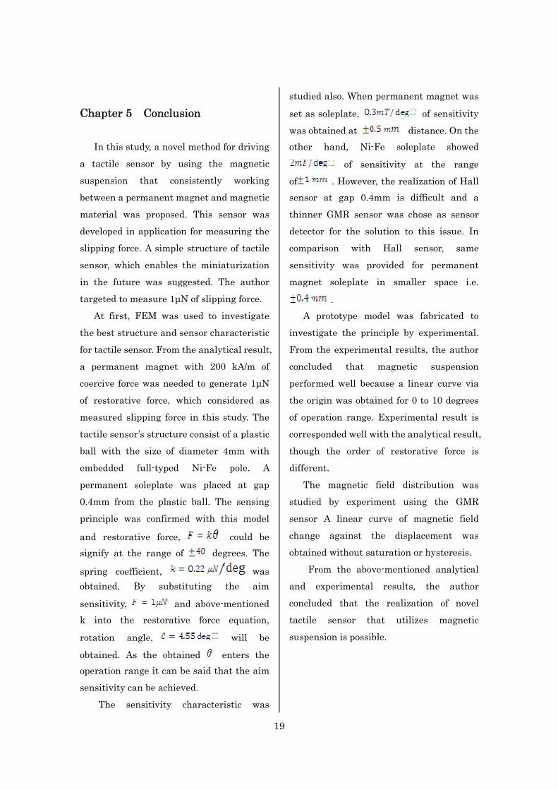
Chapter 5 Conclusion
In this study, a novel method for driving
a tactile sensor by using the magnetic
suspension that consistently working
between a permanent magnet and magnetic
material was proposed. This sensor was
developed in application for measuring the
slipping force. A simple structure of tactile
sensor, which enables the miniaturization
in the future was suggested. The author
targeted to measure 1µN of slipping force.
At first, FEM was used to investigate
the best structure and sensor characteristic
for tactile sensor. From the analytical result,
a permanent magnet with 200 kA/m of
coercive force was needed to generate 1µN
of restorative force, which considered as
measured slipping force in this study. The
tactile sensor’s structure consist of a plastic
ball with the size of diameter 4mm with
embedded full-typed Ni-Fe pole. A
permanent soleplate was placed at gap
0.4mm from the plastic ball. The sensing
principle was confirmed with this model
and restorative force, could be signify at the range of degrees. The
spring coefficient, was obtained. By substituting the aim
sensitivity, and above-mentioned k into the restorative force equation,
rotation angle, will be
obtained. As the obtained enters the operation range it can be said that the aim
sensitivity can be achieved.
The sensitivity characteristic was
studied also. When permanent magnet was
set as soleplate, of sensitivity
was obtained at distance. On the other hand, Ni-Fe soleplate showed
of sensitivity at the range
of . However, the realization of Hall sensor at gap 0.4mm is difficult and a
thinner GMR sensor was chose as sensor
detector for the solution to this issue. In
comparison with Hall sensor, same
sensitivity was provided for permanent
magnet soleplate in smaller space i.e.
. A prototype model was fabricated to
investigate the principle by experimental.
From the experimental results, the author
concluded that magnetic suspension
performed well because a linear curve via
the origin was obtained for 0 to 10 degrees
of operation range. Experimental result is
corresponded well with the analytical result,
though the order of restorative force is
different.
The magnetic field distribution was
studied by experiment using the GMR
sensor A linear curve of magnetic field
change against the displacement was
obtained without saturation or hysteresis.
From the above-mentioned analytical
and experimental results, the author
concluded that the realization of novel
tactile sensor that utilizes magnetic
suspension is possible.
20
Acknowledgement The author extends her grateful to
Professor Yasuhiro Koshimoto for advices
on the progress for this study and to Dr.
Hirofumi Han for the helpful comments. We
also appreciated the cooperation from Mr.
Kiyotami Shiraga in helping to
manufacture the components of our
experimental device. Financial support
from Panasonic Electronic Devices Co. is
gratefully acknowledged. The author also
feels strong gratitude towards the entire
smart sensing lab’s member for pleasant
student life. Lastly, the author sent her
feeling of thankfulness to Mr. Mohd Ashraf
Ismail and Mrs. Azavitra Zainal for the
moral support that gave the author
tremendous strength.
References 1. Dzung Viet Dao, Qiang Wang, Susumu
Sugiyama, “Fabrication and
Characterization of 3-DOF
Soft-Contact Tactile Sensor Utilizing
3-DOF Micro Froce Moment Sensor”,
IEEJ, 127, 177, 2007
2. M.Kohei, A.Fumihito, F.Toshio,
“Piezoelectric Vibration-Type Tactile
Sensor Using Elasticity and Viscosity
Change of Structure”,
IEEE,7,1044,2007 3. 南任靖雄,“センサと基礎技術”,工学図書
株式会社, 1994, 179-180
4. M.Tsuzuki, “樹脂と磁性薄膜を用いた可
動磁極型マイクロアクチュエータの基礎
検討”, Wakayama Univ Master Thesis
2004,p24
5. Y.Hasegawa, H.Sasaki, M.Shikida,
K.Sato, K.Itoigawa, “Magnetic
actuation of a micro-diaphragm
structure for an active tactile sensor”,
IEEE, 99, 2004
6. Y.Yoji, Mark R.Cutkosky, “ Tactile
Sensor with 3-Axis Froce and Vibration
Sensing Functions and Its Application
to Detect Rotational Slip”,
IEEE,3550-3557,1994
7. Eun-Soo Hwang, Jeong-Hoon Seo,
Yong-Jun Kim, “A Polymer-based
Flexible Tactile Sensor for Normal and
Shear Load Detection”, IEEE,MEMS
2006 Istanbul,Turkey , 714-717, 2006
8. M.Ohka, Y.Sawamoto, S.Matsukawa, T.Miyaoka, Y.Mitsuya, “ 圧覚・滑り覚同
時呈示形触覚ディスプレィ用二軸アクチ
ュエータ”, IEEJ,127,524-532,2007
Achievements 1. Tuty Rahiza Sajat, H.Han,
Y.Koshimoto, The 31st Annual
Conference on Magnetics,11aF-2(2007)
2. Tuty Rahiza Sajat, Wakayama
Embedded Information
Service(EIS)-Cluster, The 2nd Academic
Industrial Alliance Research Progress,
Poster Presentation,2006
21
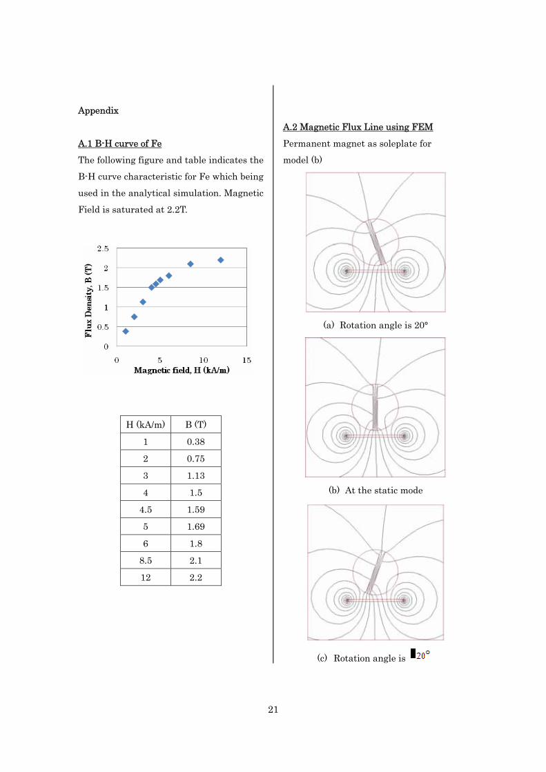
Appendix
A.1 B-H curve of Fe
The following figure and table indicates the
B-H curve characteristic for Fe which being
used in the analytical simulation. Magnetic
Field is saturated at 2.2T.
H (kA/m) B (T)
1 0.38
2 0.75
3 1.13
4 1.5
4.5 1.59
5 1.69
6 1.8
8.5 2.1
12 2.2
A.2 Magnetic Flux Line using FEM
Permanent magnet as soleplate for
model (b)
(a) Rotation angle is 20°
(b) At the static mode
(c) Rotation angle is

22
Ni-Fe soleplate as soleplate for model (b)
(a) Rotation angle is
(b) At the static mode
(c) Rotation angle is