basic troubleshooting - partshere.com 3300 all in... · consult the list of common messages later...
TRANSCRIPT

Basic troubleshooting
Table 15. Basic troubleshooting
# Verification steps Possible problems Solutions
1 Is Power On successful?When the product is connected to a grounded power source, Hewlett Packard is displayed with moving cursors indicating that the firmware code is loading, and the printer motor rotates for approximately five seconds. When the firmware is done loading (30-40 seconds after power-on), Scannerbulb management is displayed and the scan head moves back and forth for 10-15 seconds. If you lift the lid, you will see that the scanner bulb is lit. Near the end of this time, the ADF motor turns on for about two seconds.
No power due to failed power source, cable, switch, or fuse.
1. Verify that the product is plugged in.2. Verify that the power cable is functional and that the power switch is on (220v only).3. Verify that FU102 on the ECU is not open.4. If all of these conditions are correct, replace the ECU.
Printer motor does not rotate.
1. Verify that the toner cartridge is present.2. Verify that the product doors are closed.3. Verify that paper is loaded in the paper input tray.4. Verify that the printer path paper sensors are functional.5. Verify that the motor connector J1 is seated into the ECU.6. Verify that the motor is correctly mounted to the product chassis.7. If all of these conditions are correct, replace the ECU.8. If, after replacing the ECU, the printer motor still does not rotate, replace the motor.
ADF motor does not rotate or scanner bulb does not light.
1. Verify that the scanner connector is seated in the formatter and scanner formatter.2. Check all cabling on the scanner formatter.3. If the ADF motor still does not rotate, replace the ADF.4. If the scanner bulb still does not light, replace the scanner assembly.5. If the problem persists, replace parts one at a time in the following order until the problem is resolved: scanner formatter, formatter, and finally the ECU.
174 Chapter 6 - Troubleshooting EN

2 Is the product ready?The control panel should function without error messages.
Control panel displays an error.
Consult the list of common messages later in this chapter to correct the error.
Control panel is not functional.
Verify that the control panel cable is seated into both the control panel and the scanner formatter. Also check the connections between the scanner formatter and the formatter. If all cables are undamaged and seated correctly but the problem persists, replace the control panel.
Control panel display is blank, but the LEDs are lit.
1. On units that allow for firmware recovery, recover the firmware using the recovery DIMM.2. If the problem persists, replace the control panel.3. If the problem persists, replace the scanner formatter PCA.4. If the problem persists, replace the formatter.
Control panel display and LEDs function, but keys do not work.
Replace the control panel.
3 Do engine tests and self-tests print?Print an engine test, which is explained on page 200. The engine test should print without paper-feed problems or print-quality problems. Also print a configuration report (See “Internal reports” on page 209.).
Note The formatter must be connected to perform an engine test.
Engine test is successful, but the configuration report does not print.
Replace the formatter.
Engine test is not successful.
Replace the ECU.
Control panel displays an error message.
Consult the list of common messages in chapter 2 or the list of error messages in this chapter to correct the error.
Media does not move smoothly through the printer paper path.
Isolate printer paper-path problems by performing a paper-path check, which is discussed later in this chapter.
Poor print quality. See “Solving image-quality problems” on page 188.
Table 15. Basic troubleshooting (continued)
# Verification steps Possible problems Solutions
EN Basic troubleshooting 175
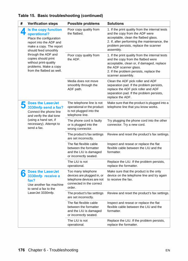
4 Is the copy function operational?Place the configuration report into the ADF and make a copy. The report should feed smoothly through the ADF and copies should print without print-quality problems. Make a copy from the flatbed as well.
Poor copy quality from the flatbed.
1. If the print quality from the internal tests and the copy from the ADF were acceptable, clean the flatbed glass.2. If, after performing the maintenance, the problem persists, replace the scanner assembly.
Poor copy quality from the ADF.
1. If the print quality from the internal tests and the copy from the flatbed were acceptable, clean or, if damaged, replace the ADF scanner glass. 2. If the problem persists, replace the scanner assembly.
Media does not move smoothly through the ADF path.
Clean the ADF pick roller and ADF separation pad. If the problem persists, replace the ADF pick roller and ADF separation pad. If the problem persists, replace the ADF.
5 Does the LaserJet 3330mfp send a fax?Connect the phone line and verify the dial tone (using a hand set, if necessary). Attempt to send a fax.
The telephone line is not operational or the product is not plugged into the telephone line.
Make sure that the product is plugged into a telephone line that you know works.
The phone cord is faulty or is plugged into the wrong connector.
Try plugging the phone cord into the other connector. Try a new cord.
The product’s fax settings are set incorrectly.
Review and reset the product’s fax settings.
The flat flexible cable between the formatter and the LIU is damaged or incorrectly seated.
Inspect and reseat or replace the flat flexible cable between the LIU and the formatter.
The LIU is not operational.
Replace the LIU. If the problem persists, replace the formatter.
6 Does the LaserJet 3330mfp receive a fax?Use another fax machine to send a fax to the LaserJet 3330mfp.
Too many telephone devices are plugged in, or telephone devices are not connected in the correct order.
Make sure that the product is the only device on the telephone line and try again to receive the fax.
The product’s fax settings are set incorrectly.
Review and reset the product’s fax settings.
The flat flexible cable between the formatter and the LIU is damaged or incorrectly seated.
Inspect and reseat or replace the flat flexible cable between the LIU and the formatter.
The LIU is not operational.
Replace the LIU. If the problem persists, replace the formatter.
Table 15. Basic troubleshooting (continued)
# Verification steps Possible problems Solutions
176 Chapter 6 - Troubleshooting EN

7 Is the software installed correctly?
Software is not installed or an error occurred during software installation.
Uninstall and then reload the product software. Make sure you use the correct installation procedure and the correct port setting.
8 Does the product print from the computer?Connect the parallel cable or USB cable to the product and the computer. Use a word-processing application to send a print job to the product.
The cable is not connected correctly.
Reconnect the cable.
An incorrect driver is selected.
Select the proper driver.
Other devices are connected to the parallel port.
Disconnect the other devices and try again to print.
There is an LPT port driver problem in Microsoft Windows.
Reset the computer’s port settings.
The formatter has failed. Replace the formatter.
9 Does the product scan to the computer?Initiate a scan from either the computer’s basic desktop software or from the product.
Other devices are connected to the parallel port.
Disconnect the other devices and try again to scan.
The computer’s parallel-port hardware is not bidirectional.
Check hardware documentation to see if the port configuration can be changed.
The BIOS settings for the parallel port are set incorrectly.Polling is turned off in HP LaserJet Director or HP LaserJet Director is not running.
Reset the computer’s port settings. If the problem persists, reset the BIOS settings in CMOS.Start HP LaserJet Director and turn on polling.
Table 15. Basic troubleshooting (continued)
# Verification steps Possible problems Solutions
EN Basic troubleshooting 177

Errors
Control panel messages The majority of the control panel messages are intended to guide the user through normal operation. The control panel displays the status of the current operation, including a page count on the second line of the display if appropriate. When the product is receiving fax data, print data, or scanning commands, the control panel displays messages to these affects. In addition, the product displays alert messages, warning messages, and critical error messages.
Alert and warning messages Alert and warning messages are displayed temporarily and may require acknowledgement by pressing menu/enter to resume or cancel. With certain warnings, the completion of a job or the quality of the output may be affected. If the alert or warning message is related to printing and the auto-continue is on, the product will attempt to resume the printing job after displaying the warning for 10 seconds without acknowledgement.
Table 16. Alert and warning messages
Message Possible causes SolutionsCleaning Mode.Wait 1-3 Min.
The product is running an internal cleaning cycle.
Wait for the product to finish the cleaning cycle. The message will clear when the cycle is finished.
Fax Busy.Canceled Send
The fax line to which you were sending a fax was busy. The product has cancelled sending the fax.
Call the recipient to ensure that fax machine is on and ready.Check that you are dialing the correct fax number.Check that the Redial On Busy option is enabled.Unplug the product telephone cord from the wall, plug in a telephone, and try making a call.Plug the product phone cord into a jack for another phone line.Try a different phone cord.If the error persists, check the flat flexible cable between the LIU and the formatter. Reseat or replace the cable.If the error persists, replace the LIU.
178 Chapter 6 - Troubleshooting EN

### Is Empty[Enter] To Add
The one-touch key or speed-dial code has not been programmed and therefore cannot be added to a group.
Press menu/enter to program the one-touch or speed-dial. If you want to program a group-dial, press cancel and use the control panel menu to create a new group. Press cancel if you do not want to program the one-touch or speed-dial.
###: [Group Name]Phbook/SpeedDial
The product is waiting for you to press a programmed one-touch key or enter a speed-dial code to a group-dial code.
Begin adding fax numbers to the group-dial code. See “Programming group-dial codes” in the User Guide on the product CD.
Canceled Copy.Clear Document
The cancel key was pressed to cancel the current job while pages were feeding from the document feeder. The cancel process will not automatically clear the document feeder.
Pull the document release door open, remove the jammed item, and close the door. Then, clear the items in the document feeder tray and start over.
Canceled Scan.Clear Document
The cancel key was pressed to cancel the current job while pages were feeding from the document feeder. The cancel process will not automatically clear the document feeder.
Pull the document release door open, remove the jammed item, and close the door. Then, clear the items in the document feeder tray and start over.
Canceled Send.Clear Document
The cancel key was pressed to cancel the current job while pages were feeding from the document feeder tray. The cancel process will not automatically clear the document feeder.
Pull the document release door open, remove the jammed item, and close the door. Then, clear the items in the document feeder tray and start over.
Comm. Error Fax communication error occurred between the product and the sender or receiver. For descriptions of communication errors see table 22, “Fax receive error codes,” on page 211, and table 23, “Fax send error codes,” on page 216.
Allow the product to retry sending the fax.Unplug the product telephone cord from the wall, plug in a telephone, and try making a call.Plug the product phone cord into a jack for another phone line.Try a different phone cord.If the error persists, check the flat flexible cable between the LIU and the formatter. Reseat or replace the cable.If the error persists, replace the LIU.
Device Busy.Try Again Later
The product is currently in use. Wait for the product to finish the current job.
Device Error.[Enter] To Cont.
There was an internal error in the product.
Press menu/enter to resume the job.
Table 16. Alert and warning messages (continued)
Message Possible causes Solutions
EN Errors 179

Doc Feeder Jam A piece of media is jammed in the document feeder tray.
Open the document release door, clear the jam, close the document release door, and reload the paper into the document feeder tray.If the error persists, replace the ADF separation pad and ADF pickup roller.
Document FeederMispick. Reload
Media in the document feeder tray was not picked up.
Remove and reload the media into the document feeder tray.If the error persists, replace the ADF pick roller and ADF separation pad.
Door Open Or NoPrint Cartridge
The print cartridge door is open or the print cartridge is not installed properly.
1. Check that the print cartridge door and left-side door are completely closed.2. Check that the print cartridge is correctly installed. (See “Print cartridge” on page 110 for more information.)3. Check that the door and print cartridge interlocks are operating correctly. (See "Paper path check" on page 206 for more information about the door interlock.)
Engine Comm.Error
The product experienced an internal communication error.
Warning message only. Job output may be affected.
Fax Busy.Redial Pending
The fax line to which you were sending a fax was busy. The product automatically redials the busy number. (See “Changing how the product redials” in the User Guide on the product CD.)
Allow the product to retry sending the fax.Call the recipient to ensure that fax machine is on and ready.Check that you are dialing the correct fax number.Unplug the product telephone cord from the wall, plug in a telephone, and try making a call.Plug the product phone cord into a jack for another phone line.Try a different phone cord.If the error persists, check the flat flexible cable between the LIU and the formatter. Reseat or replace the cable.If the error persists, replace the LIU.
Fax Memory FullCanceling Recv
During the fax transmission, the product ran out of memory. Only the pages that fit into memory will be printed.
Print all of the faxes and have the sender resend the fax. Cancel all fax jobs or clear the faxes from memory (see “Clearing faxes from memory” in the User Guide on the product CD).
Fax Memory FullCanceling Send
During the fax job, the memory filled. All pages of the fax have to be in memory for a fax job to work correctly. Only the pages that fit into memory were sent.
Print all received faxes or wait until all pending faxes are sent. Cancel all fax jobs or clear the faxes from memory (see “Clearing faxes from memory” in the User Guide on the product CD).
Table 16. Alert and warning messages (continued)
Message Possible causes Solutions
180 Chapter 6 - Troubleshooting EN
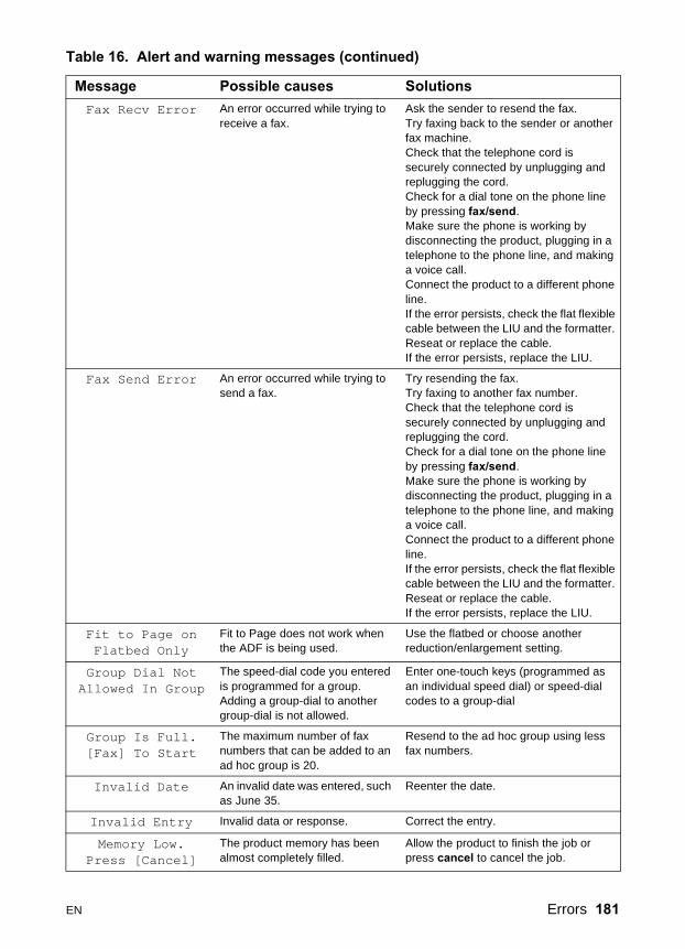
Fax Recv Error An error occurred while trying to receive a fax.
Ask the sender to resend the fax.Try faxing back to the sender or another fax machine.Check that the telephone cord is securely connected by unplugging and replugging the cord. Check for a dial tone on the phone line by pressing fax/send.Make sure the phone is working by disconnecting the product, plugging in a telephone to the phone line, and making a voice call.Connect the product to a different phone line.If the error persists, check the flat flexible cable between the LIU and the formatter. Reseat or replace the cable.If the error persists, replace the LIU.
Fax Send Error An error occurred while trying to send a fax.
Try resending the fax.Try faxing to another fax number.Check that the telephone cord is securely connected by unplugging and replugging the cord. Check for a dial tone on the phone line by pressing fax/send.Make sure the phone is working by disconnecting the product, plugging in a telephone to the phone line, and making a voice call.Connect the product to a different phone line.If the error persists, check the flat flexible cable between the LIU and the formatter. Reseat or replace the cable.If the error persists, replace the LIU.
Fit to Page onFlatbed Only
Fit to Page does not work when the ADF is being used.
Use the flatbed or choose another reduction/enlargement setting.
Group Dial NotAllowed In Group
The speed-dial code you entered is programmed for a group. Adding a group-dial to another group-dial is not allowed.
Enter one-touch keys (programmed as an individual speed dial) or speed-dial codes to a group-dial
Group Is Full.[Fax] To Start
The maximum number of fax numbers that can be added to an ad hoc group is 20.
Resend to the ad hoc group using less fax numbers.
Invalid Date An invalid date was entered, such as June 35.
Reenter the date.
Invalid Entry Invalid data or response. Correct the entry.
Memory Low.Press [Cancel]
The product memory has been almost completely filled.
Allow the product to finish the job or press cancel to cancel the job.
Table 16. Alert and warning messages (continued)
Message Possible causes Solutions
EN Errors 181
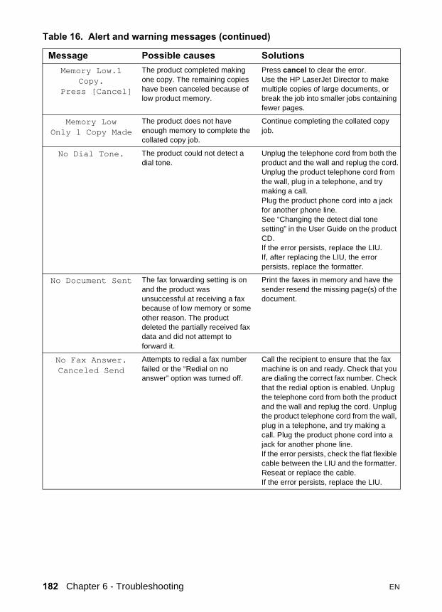
Memory Low.1Copy.
Press [Cancel]
The product completed making one copy. The remaining copies have been canceled because of low product memory.
Press cancel to clear the error.Use the HP LaserJet Director to make multiple copies of large documents, or break the job into smaller jobs containing fewer pages.
Memory LowOnly 1 Copy Made
The product does not have enough memory to complete the collated copy job.
Continue completing the collated copy job.
No Dial Tone. The product could not detect a dial tone.
Unplug the telephone cord from both the product and the wall and replug the cord.Unplug the product telephone cord from the wall, plug in a telephone, and try making a call.Plug the product phone cord into a jack for another phone line.See “Changing the detect dial tone setting” in the User Guide on the product CD.If the error persists, replace the LIU.If, after replacing the LIU, the error persists, replace the formatter.
No Document Sent The fax forwarding setting is on and the product was unsuccessful at receiving a fax because of low memory or some other reason. The product deleted the partially received fax data and did not attempt to forward it.
Print the faxes in memory and have the sender resend the missing page(s) of the document.
No Fax Answer.Canceled Send
Attempts to redial a fax number failed or the “Redial on no answer” option was turned off.
Call the recipient to ensure that the fax machine is on and ready. Check that you are dialing the correct fax number. Check that the redial option is enabled. Unplug the telephone cord from both the product and the wall and replug the cord. Unplug the product telephone cord from the wall, plug in a telephone, and try making a call. Plug the product phone cord into a jack for another phone line.If the error persists, check the flat flexible cable between the LIU and the formatter. Reseat or replace the cable.If the error persists, replace the LIU.
Table 16. Alert and warning messages (continued)
Message Possible causes Solutions
182 Chapter 6 - Troubleshooting EN

No Fax Answer.Redial Pending
You tried to send a fax, but the receiving fax line did not answer. The product attempts to redial after a few minutes.
Allow the product to retry sending the fax.Call the recipient to ensure that the fax machine is on and ready.Check that you are dialing the correct fax number.Check that the Redial-No Answer option is enabled.Unplug the product telephone cord from the wall, plug in a telephone, and try making a call.Plug the product phone cord into a jack for another phone line.Try a different phone cord.If the error persists, check the flat flexible cable between the LIU and the formatter. Reseat or replace the cable.If the error persists, replace the LIU.
No Fax Detected The product answered the incoming call but did not detect that a fax machine was calling.
Allow the product to retry receiving the fax.Unplug the product telephone cord from the wall, plug in a telephone, and try making a call.Plug the product phone cord into a jack for another phone line.Try a different phone cord.If the error persists, check the flat flexible cable between the LIU and the formatter. Reseat or replace the cable.If the error persists, replace the LIU.
No Fax PagesTo Reprint
The product attempted to execute “Reprint Last Fax” when nothing was in memory.
Receive a fax before attempting to use this option.
Not EnoughMemory.Try Later
There is not enough memory to start a new job.
Wait until the current job is finished before starting a new job.
Out of Range An invalid number was entered. Correct the entry.
Printer Jam.Clear Paper Path
The product has detected a jam. Clear the jam. The job should continue to print. If it does not, try reprinting the job.If media jams frequently, see Chapter 3, “Maintenance.”
Printer Mispick[Enter]To Resume
The print engine has failed to pick up a piece of media.
Reload the paper in the paper input tray and press menu/enter to continue the job. If the error persists, replace the printer pickup roller.
Printer Tray IsEmpty.Add Paper
The paper input tray is empty. Load media. If media is already loaded, remove it. Check for and remove any jam, and then reload the stack of media in the paper input tray.
Table 16. Alert and warning messages (continued)
Message Possible causes Solutions
EN Errors 183
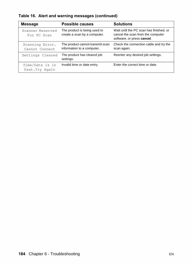
Scanner ReservedFor PC Scan
The product is being used to create a scan by a computer.
Wait until the PC scan has finished, or cancel the scan from the computer software, or press cancel.
Scanning Error.Cannot Connect
The product cannot transmit scan information to a computer.
Check the connection cable and try the scan again.
Settings Cleared The product has cleared job settings.
Reenter any desired job settings.
Time/Date is inPast.Try Again
Invalid time or date entry. Enter the correct time or date.
Table 16. Alert and warning messages (continued)
Message Possible causes Solutions
184 Chapter 6 - Troubleshooting EN

Critical error messagesCritical error messages may indicate some kind of failure. Cycling the power may fix the problem. If a critical error persists, the product may require service.
Table 17. Critical error messages
Message Cause Solution50 Fuser Error The product has experienced an
internal hardware error.Disconnect the power cable from the product, wait at least 20 minutes, then reconnect the power cable and wait for the product to initialize.Check the cabling connections to the heating element.Perform the heating element check (see page 203).If the error persists, replace the heating element.If, after replacing the heating element, the error persists, replace the ECU.
51 Laser Error The product has experienced an internal hardware error.
Disconnect the power cable from the product, wait at least 30 seconds, then reconnect the power cable and wait for the product to initialize.Check the cabling connections to the laser scanner assembly.Try connecting the product to a different power source or surge protector.If the error persists, replace the laser scanner assembly.
52 Scanner Error The product has experienced an internal hardware error.
Disconnect the power cable from the product, wait at least 30 seconds, then reconnect the power cable and wait for the product to initialize.Try connecting the product to a different power source or surge protector.If the error persists, replace the laser scanner assembly.
79 ErrorPowerOff>PowerOn
The product has experienced an internal firmware error.
Disconnect the power cable from the product, wait at least 30 seconds, then reconnect the power cable and wait for the product to initialize.If the error persists, upgrade the firmware (page 207).
EN Errors 185
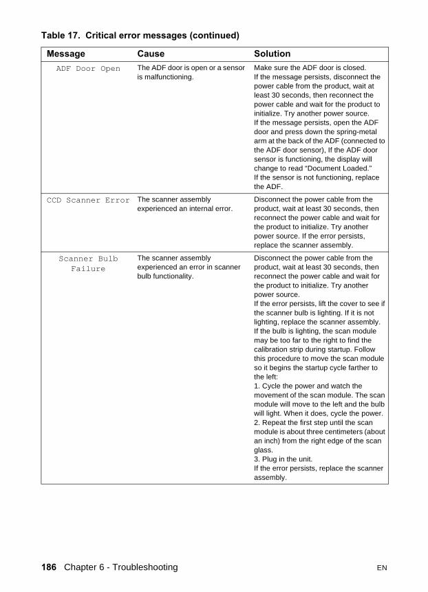
ADF Door Open The ADF door is open or a sensor is malfunctioning.
Make sure the ADF door is closed.If the message persists, disconnect the power cable from the product, wait at least 30 seconds, then reconnect the power cable and wait for the product to initialize. Try another power source. If the message persists, open the ADF door and press down the spring-metal arm at the back of the ADF (connected to the ADF door sensor), If the ADF door sensor is functioning, the display will change to read “Document Loaded.”If the sensor is not functioning, replace the ADF.
CCD Scanner Error The scanner assembly experienced an internal error.
Disconnect the power cable from the product, wait at least 30 seconds, then reconnect the power cable and wait for the product to initialize. Try another power source. If the error persists, replace the scanner assembly.
Scanner BulbFailure
The scanner assembly experienced an error in scanner bulb functionality.
Disconnect the power cable from the product, wait at least 30 seconds, then reconnect the power cable and wait for the product to initialize. Try another power source.If the error persists, lift the cover to see if the scanner bulb is lighting. If it is not lighting, replace the scanner assembly.If the bulb is lighting, the scan module may be too far to the right to find the calibration strip during startup. Follow this procedure to move the scan module so it begins the startup cycle farther to the left:1. Cycle the power and watch the movement of the scan module. The scan module will move to the left and the bulb will light. When it does, cycle the power.2. Repeat the first step until the scan module is about three centimeters (about an inch) from the right edge of the scan glass.3. Plug in the unit.If the error persists, replace the scanner assembly.
Table 17. Critical error messages (continued)
Message Cause Solution
186 Chapter 6 - Troubleshooting EN

Checking the print cartridge Image formation defects are frequently the result of problems in the print cartridge. If there is any doubt, always replace the print cartridge before troubleshooting image defects.
Use the following checklist to make sure that the print cartridge is still operable.
� Make sure that the print cartridge is seated properly.
� Inspect the print cartridge for toner level.
� Check the expiration date stamped on the print cartridge box.
� Check the print cartridge to see if it has been disassembled or refilled.
� Inspect the print cartridge to see if toner is leaking through worn seals.
� Check the surface of the photosensitive drum in the cartridge to see if it has been damaged or scratched. Touching the drum contaminates the photosensitive surface and can cause spotting and image defects.
� Blurred areas on printed pages indicate that the photosensitive drum in the cartridge has been overexposed to light. Because overexposure to light causes permanent damage to the photosensitive drum, the cartridge should be replaced.
Note A print cartridge weighs approximately 863 gm. (30.5 oz.) when it is full, approximately 766 gm. (27.0 oz.) when it first fades, and approximately 742 gm. (26.2 oz.) when it is empty.
To redistribute toner in the print cartridgeBefore installing a new print cartridge or when toner begins to run low, redistribute the toner by rotating the cartridge back and forth five or six times.
EN Errors 187

Solving image-quality problems Use the following tables to help solve problems with printed pages.
If the problem occurs when printing, see table 18, “Solving print image-quality problems,” on page 188.
If the problem occurs when copying or scanning, see table 19, “Solving scanning (copying) image-quality problems,” on page 194.
Also, see table 20, “Solving print paper-feed problems,” on page 197 and “Solving scanner (copier) paper-feed problems” on page 199.
Solving print image-quality problems
Table 18. Solving print image-quality problems
Problem Cause SolutionPages do not print.
The product is not plugged in. Make sure that the product is plugged into a live wall outlet or power strip.
The computer cable is loose. Check that the parallel cable between the product and the computer is securely connected.
The tape was not removed from the print cartridge.
Remove the print cartridge, remove the tape, and return the print cartridge. See “Print cartridge” on page 110.
The print cartridge is out of toner. Replace the print cartridge. (See “Print cartridge” on page 110.)
The media you are using does not meet HP’s specifications (for example, it is too moist or too rough).
Make sure that the media meets specifications detailed in the Print Media Guide for the HP LaserJet family.
Parts of the page around the edges are not printing.
The product cannot print to the edge of the paper. The printer has minimum margins on each edge of 4.23 mm (0.167 in.
To get the image to fit into this printable area, slightly reduce the size of the image.
The reduction setting is set incorrectly. Check the reduction setting in the “Print” or “Setup” window from within the program you are using.
188 Chapter 6 - Troubleshooting EN

Toner specks appear on the printed page..
The media you are using does not meet HP’s specifications (for example, it is too moist or too rough).
Make sure that the media meets specifications detailed in the Print Media Guide for the HP LaserJet family.
The print path needs to be cleaned. Clean the print path. (See “Cleaning the print path” on page 59.)
Characters are only partially printed (also referred to as dropouts).
A single sheet of paper is defective. Try reprinting the job.
The print density needs to be adjusted. Adjust the print density from the device configuration utility.
The moisture content of the paper is inconsistent, or the paper has moist or wet spots on the surface.
Make sure that the media meets HP’s specifications.
The paper was damaged by inconsistent manufacturing processes.
Make sure that the media meets specifications detailed in the Print Media Guide for the HP LaserJet family.
A draft mode or economy mode is selected in the software.
Try the normal or best setting.
The print cartridge is defective. Replace the print cartridge.
Vertical lines appear on the printed page.
The priority input tray is not in place. Adjust the priority input tray.
The photosensitive drum inside the print cartridge is scratched.
Replace the print cartridge.
The fuser is damaged or has an obstruction.
Replace the fuser.
Table 18. Solving print image-quality problems (continued)
Problem Cause Solution
EN Errors 189

The printed page has a gray background.
The priority input tray is not in place. Adjust the priority input tray.
The print density setting is too high. Decrease the amount of background shading through the device configuration utility.
The media basis weight is too high. Change the media to a lower basis weight.
The humidity level is too low. Very low humidity can increase the amount of background shading. Move the product to a different location, or decrease the background shading through the device configuration utility.
The print cartridge needs to be replaced. Replace the print cartridge.
Toner smears appear on the printed page.
If the toner smears appear on the leading edge of the media, the media guides are dirty.
Wipe the media guides with a dry, lint-free cloth.
The media you are using does not meet HP’s specifications (for example, it is too moist or too rough).
Make sure that the media meets specifications detailed in the Print Media Guide for the HP LaserJet family.
The print cartridge needs to be replaced. Replace the print cartridge.
The fuser temperature is too low. Select Optimize for: in the Paper tab of the driver. Make sure that it is set for the appropriate media.Perform the heating element check (see page 203).If the error persists, replace the heating element.If, after replacing the heating element, the error persists, replace the ECU.
Table 18. Solving print image-quality problems (continued)
Problem Cause Solution
190 Chapter 6 - Troubleshooting EN

The toner is loose, and it does not stay attached to the printed page.
The inside of the printer is dirty. Clean the print path. (See “Cleaning the print path” on page 59.)
The media you are using does not meet HP’s specifications (for example, it is too moist or too rough).
Make sure that the media meets specifications detailed in the Print Media Guide for the HP LaserJet family.
The print cartridge needs to be replaced. Replace the print cartridge.
The driver is not set for the correct media.
1. Select Optimize for: in the Paper tab of the driver. Select the correct media.2. Select the correct media through the device configuration utility.
The power strip is not working correctly. Plug the product directly into an AC outlet.
The fuser temperature is too low. Select Optimize for: in the Paper tab of the driver. Make sure that it is set for the appropriate media.Perform the heating element check (see page 203).If the error persists, replace the heating element.If, after replacing the heating element, the error persists, replace the ECU.
Repetitive vertical defects appear on the printed page.
If the repetitive mark occurs at equal distance between marks, either the print cartridge or a printer roller is damaged.
Use the defect ruler to identify the spacing. Check the appropriate component and replace if necessary. (See “Repetitive image defect ruler” on page 236.)
The internal parts have toner on them. If the defects occur on the back of the page, the problem will probably correct itself after a few more printed pages.
Otherwise, clean the printer. (See “Cleaning the print path” on page 59.)
The driver is not set for the correct media.
1. Select Optimize for: in the Paper tab of the driver. Select the correct media. (This affects the current print job only.)2. Select the correct media through the device configuration utility.
Table 18. Solving print image-quality problems (continued)
Problem Cause Solution
EN Errors 191
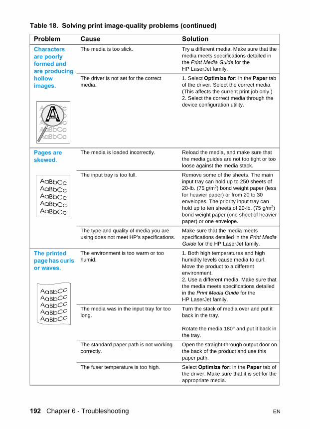
Characters are poorly formed and are producing hollow images.
The media is too slick. Try a different media. Make sure that the media meets specifications detailed in the Print Media Guide for the HP LaserJet family.
The driver is not set for the correct media.
1. Select Optimize for: in the Paper tab of the driver. Select the correct media. (This affects the current print job only.)2. Select the correct media through the device configuration utility.
Pages are skewed.
The media is loaded incorrectly. Reload the media, and make sure that the media guides are not too tight or too loose against the media stack.
The input tray is too full. Remove some of the sheets. The main input tray can hold up to 250 sheets of 20-lb. (75 g/m2) bond weight paper (less for heavier paper) or from 20 to 30 envelopes. The priority input tray can hold up to ten sheets of 20-lb. (75 g/m2) bond weight paper (one sheet of heavier paper) or one envelope.
The type and quality of media you are using does not meet HP’s specifications.
Make sure that the media meets specifications detailed in the Print Media Guide for the HP LaserJet family.
The printed page has curls or waves.
The environment is too warm or too humid.
1. Both high temperatures and high humidity levels cause media to curl. Move the product to a different environment.2. Use a different media. Make sure that the media meets specifications detailed in the Print Media Guide for the HP LaserJet family.
The media was in the input tray for too long.
Turn the stack of media over and put it back in the tray.
Rotate the media 180° and put it back in the tray.
The standard paper path is not working correctly.
Open the straight-through output door on the back of the product and use this paper path.
The fuser temperature is too high. Select Optimize for: in the Paper tab of the driver. Make sure that it is set for the appropriate media.
Table 18. Solving print image-quality problems (continued)
Problem Cause Solution
192 Chapter 6 - Troubleshooting EN

Large amounts of toner are scattered around the characters.
The media resistivity is too high. 1. Use a different media. Make sure that the media meets specifications detailed in the Print Media Guide for the HP LaserJet family.2. Turn the stack of media over and put it back in the tray.3. Use media that is designed for laser printers.
Vertical white stripes appear.
The media you are using does not meet HP’s specifications (for example, it is too moist or too rough).
Make sure that the media meets specifications detailed in the Print Media Guide for the HP LaserJet family.
The toner is low. Gently shake the print cartridge back and forth to redistribute the toner.
Table 18. Solving print image-quality problems (continued)
Problem Cause Solution
EN Errors 193

Solving scanning (copying) image-quality problems
Table 19. Solving scanning (copying) image-quality problems
Problem Cause SolutionPages do not print.
The product is not plugged in. Make sure that the product is plugged into a live wall outlet or power strip.
The computer cable is loose. Check that the cable between the product and the computer is securely connected.
The tape was not removed from the print cartridge.
Remove the print cartridge, remove the tape, and return the print cartridge. (See “Print cartridge” on page 110.)
The print cartridge is out of toner. Replace the print cartridge. (See “Print cartridge” on page 110.)
The media you are using does not meet HP’s specifications (for example, it is too moist or too rough).
Make sure that the media meets specifications detailed in the Print Media Guide for the HP LaserJet family.
The original was loaded upside-down. Load the original with the side to be scanned facing up in the ADF or down on the flatbed.
Parts of the page around the edges are not printing.
The product cannot print to the edge of the paper. The printer has minimum margins on each edge of 4.23 mm (0.167 in.
To get the image to fit into this printable area, slightly reduce the size of the image.
If copying, the reduction setting is incorrect.
Copied images will be clipped if the image on the original is too close to the edge of the original.
The paper size setting is incorrect. Set the correct page size using the control panel menu.
Vertical white stripes appear.
The media you are using does not meet HP’s specifications (for example, it is too moist or too rough).
Make sure that the media meets specifications detailed in the Print Media Guide for the HP LaserJet family.
The toner is low. Gently shake the print cartridge back and forth to redistribute the toner.
If copying with the ADF, the ADF glass is dirty.
1. Clean the ADF glass.2. If the problem persists, replace the print cartridge.3. If the problem persists, replace the fuser assembly.
194 Chapter 6 - Troubleshooting EN

Copies or scanned images are too light or too dark.
The contrast is not set correctly. 1. Adjust the contrast and resolution settings from the control panel menu or HP LaserJet Director or HP Document Manager.2. Check that the contrast and resolution settings are correct. See the user guide for more information.
The original image is very light or very dark.
Adjust the resolution and contrast setting(s) from the control panel menu or toolbox on the HP LaserJet Director or HP Document Manager.
The scanned image is too light or too dark because the original was on colored paper.
If the original was on a colored paper, including brown recycled paper, the text might not be clear. Adjust the resolution, contrast, and brightness settings from the toolbox on the HP LaserJet Director or HP Document Manager.
Vertically-aligned black streaks or smears appear on successive pages.
The printer needs to be cleaned. Clean the printer. (See “Cleaning the print path” on page 59.)
If copying with the ADF, the ADF glass is dirty.
Clean the ADF path. (See “Cleaning the product” on page 57.)
A component is damaged. (For example, the photosensitive drum inside the print cartridge is scratched.)
1. Replace the print cartridge if it is damaged and if maintenance procedures do not improve print quality. 2. Replace the scanner assembly.
Scanned images have black dots or streaks.
The scanner glass is dirty. Clean the ADF path and flatbed glass. (See “Cleaning the product” on page 57.)
There is a problem with the scanner assembly.
Replace the scanner assembly.
Table 19. Solving scanning (copying) image-quality problems (continued)
Problem Cause Solution
EN Errors 195

Scanned text is not clear.
The contrast, resolution, or brightness needs to be adjusted before scanning.
1. Adjust the contrast and resolution settings from the HP LaserJet Director or HP Document Manager.3. Check that the contrast and resolution settings are correct. See the user guide section for more information.
The original is on colored paper. If the original is on colored paper, including brown recycled paper, the text might not be clear. Try adjusting the resolution, contrast, and brightness settings from the toolbox on the HP LaserJet Director or HP Document Manager.
There is a problem with the scanner assembly.
Replace the scanner assembly.
Images are scanning at a reduced size.
The HP software settings are set to reduce the scanned image.
1. Adjust the settings in the HP LaserJet Director or HP Document Manager.2. Adjust the Quick Copy settings.3. Adjust the settings in the HP LaserJet Copier software.
Large amounts of toner are scattered around the characters.
The media resistivity is too high. 1. Use a different media type. Make sure that the media meets specifications detailed in the Print Media Guide for the HP LaserJet family.2. Turn the stack of media over and put it back in the tray.3. Use media that is designed for laser printers.
Table 19. Solving scanning (copying) image-quality problems (continued)
Problem Cause Solution
196 Chapter 6 - Troubleshooting EN

Solving paper-feed problems
Use the following table to solve problems related to moving paper or documents through the product.
If the problem occurs when copying or scanning, see table 21, “Solving scanner paper-feed problems,” on page 199.
Solving print paper-feed problems
Table 20. Solving print paper-feed problems
Problem Cause SolutionPages are coming out curled or wrinkled.
Paper curl is inherent to the laser printing processes, and occurs when paper is subjected to heat. Paper curl tends to relax as the paper cools while resting on a flat surface.
Make sure that the media meets specifications detailed in the Print Media Guide for the HP LaserJet family.
Paper is curled or wrinkled when using the paper output bin.
Open the straight-through output door on the back of the product and use this paper path. Reset the fuser mode to the default.
Paper is not stored properly. Whenever possible, store paper in its sealed ream at room temperature.
The media is too long for the printer output bin.
Use the long media extension.
The fuser temperature is too high. Select Optimize for: in the Paper tab of the driver. Make sure that it is set for the appropriate media.
Print is misaligned on the page (skewed pages).
The main input tray is overfilled. Remove some of the media.
The paper guides are not set correctly, are broken, or are missing.
Be sure to center the paper with the side media guides. Verify that the guides are not adjusted too tightly or too loosely against the paper. Check for broken or missing guides and replace as necessary.
The paper’s weight or surface finish does not meet HP’s specifications.
Make sure that the media meets specifications detailed in the Print Media Guide for the HP LaserJet family.
EN Solving paper-feed problems 197

The printer feeds multiple sheets or jams frequently from the main input tray or priority input tray.
Paper guides are not adjusted properly. Slide the guides against the sides of the stack in the main input tray or the priority input tray to center the paper. Make sure the guides are not adjusted too tightly.
Paper was not removed from the main input tray before refilling the tray.
Always remove paper from the main input tray before refilling it.
The main input tray is overfilled. Remove some of the sheets. The main input tray can hold up to 250 sheets of 20-lb. (75 g/m2) bond weight paper (less for heavier paper) or from 20 to 30 envelopes.
The priority input tray is overfilled. Remove some of the sheets. The priority input tray can hold up to ten sheets of 20-lb. (75 g/m2) bond weight paper (one sheet of heavier paper) or one envelope.
The paper was poorly cut by the manufacturer and is sticking together.
“Break” the ream of paper by curving it into an upside-down u-shape; this can effectively decrease multifeeds. Also try turning the paper around to feed the opposite end first, or use a different type of paper.
The paper does not meet HP’s specifications for print media.
Make sure that the media meets specifications detailed in the Print Media Guide for the HP LaserJet family.
The output capacity was exceeded in the paper output bin.
Do not allow more than 125 sheets of 20-lb. (75 g/m2) bond weight paper (less for heavier paper) to fill the paper output bin.
The pickup roller is dirty. Clean the pickup roller. See “Cleaning the printer pickup roller” on page 61.
The pickup roller is damaged. Replace the pickup roller. (See “Replacing the printer pickup roller” on page 63.)
The separation pad is dirty. Clean the separation pad. (See “Cleaning the printer separation pad” on page 62.)
The separation pad is damaged. Replace the separation pad. (See “Replacing the printer separation pad” on page 65.)
A sensor is not operating properly. Check the sensors to make sure that none of them are jammed. If a sensor cannot be “unjammed,” replace the sensor.
Table 20. Solving print paper-feed problems (continued)
Problem Cause Solution
198 Chapter 6 - Troubleshooting EN

Solving scanner (copier) paper-feed problems
Table 21. Solving scanner paper-feed problems
Problem Cause SolutionLong pages stop feeding through the ADF.
The document is too long. The maximum document length is 381 mm (15 in). If your document is too long, copy each segment of it and scan the copies.
The paper delivery sensor is damaged. Free the paper delivery sensor. If you cannot free it, replace it.
Scanned items are crooked.
The media input tray guides are not set correctly, are broken, or are missing.
Be sure to center the paper with the media input tray guides. Verify that the guides are not adjusted too tightly or too loosely against the paper. Check for broken or missing guides and replace as necessary.
The ADF feeds multiple sheets or jams frequently from the media input tray.
The media input tray guides are not adjusted properly.
Remove the document from the media input tray. Straighten the item, then reinsert it. Slide the guides against the sides of the item to center it. Make sure the guides are not adjusted too tightly.
The media input tray is overfilled. Remove some of the sheets. The media input tray can hold up to 50 pages, depending on the thickness of the pages.
The item was too thick, too slick, or otherwise did not meet specifications.
Make sure that the media meets specifications detailed in the Print Media Guide for the HP LaserJet family.
The ADF pickup roller is dirty. Clean the ADF pickup roller. (See the user guide.)
The ADF document feed guide is not installed properly.
Ensure that both sides of the ADF document feed guide are snapped in properly.
The ADF pickup roller is damaged or worn.
Replace the ADF pickup roller. (See the user guide).
The ADF separation pad is dirty, damaged, or worn.
Replace the ADF separation pad. (See “ADF separation pad” on page 123.)
The sensor is not operating properly. Check the sensor to make sure it is not jammed. If a sensor cannot be corrected, replace the ADF assembly.
There is a problem in the ADF path. Check the path for obstructions. Readjust as necessary or replace the ADF assembly.
EN Solving paper-feed problems 199

Functional checks
Engine testThe engine test is used to verify that the print engine is functioning correctly. The formatter is bypassed during an engine test, so the engine test is useful for isolating printer problems. The engine test prints horizontal lines down the entire printable area of a page and is also useful for checking and adjusting registration.
Printing an engine testThe engine test switch is inside the left side door, below the formatter.
To print an engine test, open the left side door and, using a non-conductive probe, depress the engine test switch. A single test page will print.
CAUTION Use a non-conductive probe to depress the engine test switch. Inserting a conductive probe to depress the switch can damage the product.
Note The formatter must be connected to the ECU to perform an engine test. (See callout 1 in figure 86 on page 165.) Otherwise, the printer does not print.
You must override the print cartridge door interlock (SW 301). (See “Paper path check” on page 206.)
Figure 94. Engine test switch
21
200 Chapter 6 - Troubleshooting EN

Half self-test functional check The electrophotographic process can be subdivided into the following stages:
� image formation stage (charges the drum and writes a latent image to the drum with the laser)
� development stage (forms a toner image on the drum)
� transfer stage (transfers the image to paper)
� cleaning stage (removes excess toner from the drum)
� fusing stage (applies heat and pressure to make the image on paper permanent)
To perform a half self-test checkThe purpose of the half self-test check is to determine which process is malfunctioning.
1 Print a self-test page. (See “Troubleshooting tools” on page 209.)
2 Open the print cartridge door after the paper advances halfway through the printer (about five seconds after the motor begins rotation). The leading edge of the paper should have advanced past the print cartridge.
3 Remove the print cartridge.
4 Open the print cartridge drum shield to view the drum surface. If a dark and distinct toner image is present on the drum surface, assume that the first two functions of the electrophotographic process are functioning (image formation and development). Troubleshoot the failure as a transfer or fusing problem.
To perform other checks If there is no image on the photosensitive drum, perform these checks:
1 Make sure you removed the entire length of the sealing tape from the print cartridge before you installed the cartridge.
2 Perform a drum rotation functional check. (See “Drum rotation functional check” on page 202.)
3 Perform a high-voltage power supply check. (See “High-voltage power supply check” on page 204.)
EN Functional checks 201

Drum rotation functional checkThe photosensitive drum, located in the print cartridge, must rotate for the print process to work. The photosensitive drum receives its drive from the main drive assembly.
Note This test is especially important if refilled print cartridges have been used.
1 Open the print cartridge door.
2 Remove the print cartridge.
3 Mark the drive gear on the cartridge with a felt-tipped marker. Note the position of the mark.
4 Install the print cartridge and close the print cartridge door. The startup sequence should rotate the drum enough to move the mark.
5 Open the print cartridge door and inspect the gear that was marked in step 3. Verify that the mark moved.
If the mark did not move, inspect the main drive assembly to make sure that it is meshing with the print cartridge gears. If the drive gears appear functional and the drum does not move, replace the print cartridge.
202 Chapter 6 - Troubleshooting EN

Heating element check Paper passes between the heating element and a soft pressure roller to fuse toner to the paper.
1 Unplug the product for at least ten minutes. Remove the right cover (page 113) and back cover (page 130).
2 Verify that the thermistor connector is seated into both the product chassis and the ECU.
3 Unplug the fuser cable connector (callout 1) by pressing and releasing the tab on the back of the connector. To measure the continuity of the heating element, measure the resistance between the two pins at the end of the cable.
Note Normal resistance is 25 ohms +/- 10 ohms for the 110V product and 80 ohms +/- 20 ohms for the 220V product.
If no resistance is measured, replace the fuser.
4 Remove the thermistor connector (callout 2), and measure the resistance between J206 pins one and two and between J206 pins three and four.
Note Normal resistance between both pairs of pins is 370K ohms +/- 50K ohms at 20° C (68° F).
5 If no resistance is measured, replace the fuser.
Figure 95. Locating connectors for the heating element check
2
2
1
2
EN Functional checks 203
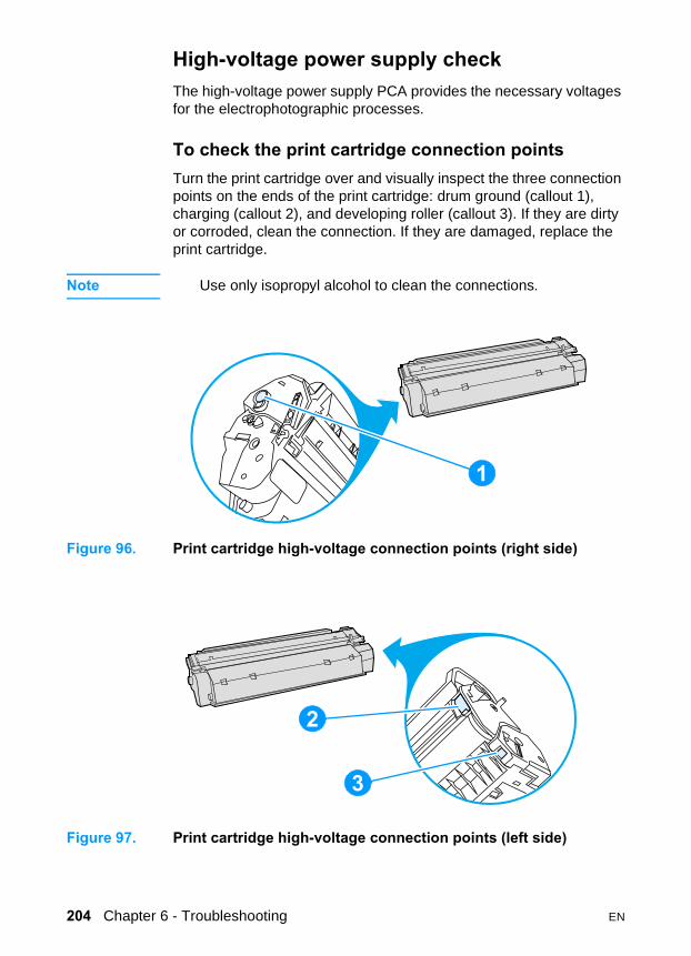
High-voltage power supply checkThe high-voltage power supply PCA provides the necessary voltages for the electrophotographic processes.
To check the print cartridge connection pointsTurn the print cartridge over and visually inspect the three connection points on the ends of the print cartridge: drum ground (callout 1), charging (callout 2), and developing roller (callout 3). If they are dirty or corroded, clean the connection. If they are damaged, replace the print cartridge.
Note Use only isopropyl alcohol to clean the connections.
Figure 96. Print cartridge high-voltage connection points (right side)
Figure 97. Print cartridge high-voltage connection points (left side)
21
2
2
2
3
204 Chapter 6 - Troubleshooting EN
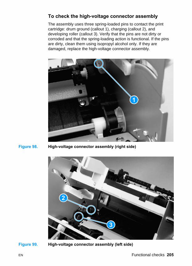
To check the high-voltage connector assembly The assembly uses three spring-loaded pins to contact the print cartridge: drum ground (callout 1), charging (callout 2), and developing roller (callout 3). Verify that the pins are not dirty or corroded and that the spring-loading action is functional. If the pins are dirty, clean them using isopropyl alcohol only. If they are damaged, replace the high-voltage connector assembly.
Figure 98. High-voltage connector assembly (right side)
Figure 99. High-voltage connector assembly (left side)
21
2
2
2
3
EN Functional checks 205

Paper path check If paper is not being picked up or is not moving through the paper path, you might want to observe all of the paper motion activities. Overriding the door interlock (SW301) allows you to observe:
� motor rotation
� solenoid action
� kick plate motion
� paper pickup roller motion
� drive roller, transfer roller, fuser roller and gear, and delivery roller motion
To override SW301
Figure 100. Overriding SW301
1 Open the left side door and print cartridge door. Disengage the two print cartridge door arms.
2 Install the print cartridge, which will press SW301.
3 Press down the laser/scanner interlock switch (callout 1) on the laser/scanner.
4 While SW301 and the laser/scanner interlock are engaged, perform an engine test or self-test to observe paper motion. (See procedures elsewhere in this chapter.)
21
206 Chapter 6 - Troubleshooting EN

Updating or recovering the firmware code
At product release, all units are manufactured with flash-memory- based formatters allowing the firmware code to be updated in the event that new firmware is released for the product or recovered in the event of code corruption or failure. When the product is mature, formatters are manufactured with permanent ROM, and updating or recovering the firmware code is not necessary.
Firmware update via flash executableThe configuration page lists the firmware version of the product. On flash-memory-based products, you can update the firmware code by downloading the latest flash executable for the product and running the program according to the readme instructions that come with it. If the firmware should become corrupted or fail (usually because of an interruption when attempting to update the firmware), the product will no longer function. In this case, a firmware recovery DIMM is available from HP.
Firmware recovery DIMMA firmware recovery DIMM can be obtained from HP in the rare event that the firmware in flash memory becomes corrupted. When the DIMM is installed in the DIMM slot on the formatter and the product is powered up, the DIMM loads the latest firmware code into the product.
EN Updating or recovering the firmware code 207

To use the firmware recovery DIMM 1 Order a firmware recovery DIMM (RDIMM) from HP. Retain the
return mailer.
2 Open the left side door and install the DIMM.
Figure 101. Using the firmware recovery DIMM
3 Plug in the product. The recovery DIMM takes a few minutes to automatically restore both blocks of firmware code. Wait until you see the message Complete in the display.
4 Unplug or turn off the product and remove the recovery DIMM.
5 Restore power to the product. It should start up normally.
6 Return the recovery DIMM in the provided packaging to HP.
21
208 Chapter 6 - Troubleshooting EN

Troubleshooting tools
Internal reports Use the control panel to print configuration reports and demonstration pages. The configuration report shows the settings selected from the control panel. Printing a configuration report is also considered a "self test" for the printer, although any of the reports can serve this purpose. A printout of the control panel menu structure is a useful reference if you alter settings in the menu.
To print a configuration report, demonstration page, or menu structure1 Press menu/enter.
2 Use the < or > key to select Reports and then press menu/enter.
3 Use the < or > key to select either Config Report, DemoPage, or Menu Structure and then press menu/enter. The product exits the Menu settings and prints the report.
Printing all fax reports at onceTo print all fax reports at once:
1 Press menu/enter.
2 Use the < or > key to select Reports and then press menu/enter.
3 Use the < or > key to select All Fax Reports and then press menu/enter. The product exits the Menu settings and prints the reports.
When you print all reports at once, the following reports are printed:
� Fax activity log—recent faxes sent and received, and their status
� Billing log (if enabled)—prints by billing code
� Block fax list (if enabled)—fax numbers you have blocked
� Configuration report—current control panel settings, including the following sections:
• System information
• Reports
• Fax settings
EN Troubleshooting tools 209
• User defaults
• Service
• Page counts
� Speed-dial report—one-touch, speed-dial, and group-dial report
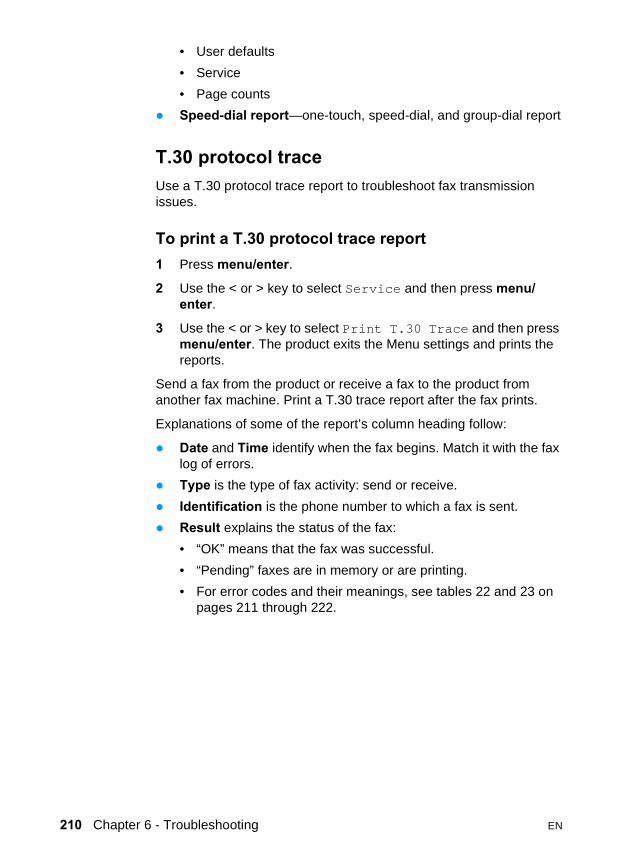
T.30 protocol traceUse a T.30 protocol trace report to troubleshoot fax transmission issues.
To print a T.30 protocol trace report1 Press menu/enter.
2 Use the < or > key to select Service and then press menu/enter.
3 Use the < or > key to select Print T.30 Trace and then press menu/enter. The product exits the Menu settings and prints the reports.
Send a fax from the product or receive a fax to the product from another fax machine. Print a T.30 trace report after the fax prints.
Explanations of some of the report’s column heading follow:
� Date and Time identify when the fax begins. Match it with the fax log of errors.
� Type is the type of fax activity: send or receive.
� Identification is the phone number to which a fax is sent.
� Result explains the status of the fax:
• “OK” means that the fax was successful.
• “Pending” faxes are in memory or are printing.
• For error codes and their meanings, see tables 22 and 23 on pages 211 through 222.
210 Chapter 6 - Troubleshooting EN

Table 22. Fax receive error codes
Error code Error definition Solution200 The fax session has completed without
errors.None required.
221 User has pressed cancel causing fax session to be prematurely halted.
Allow the product to receive the fax.
222 The local machine has answered a call but has been unable to detect the presence of a calling fax machine. Typically this is caused by the local fax machine answering a voice call.-Or-The remote user canceled the fax transmission by pressing cancel immediately prior to, or just as the local machine answered the call.-Or-The remote machine automatically ended the call immediately prior to, or just as the local machine answered the call.-Or-The remote (calling) fax machine determined there was a feature incompatibility between the two and disconnected immediately before transmitting any further fax tones or T.30 frames. (This is a very rare and non-standard behavior.)
1 Confirm that the remote caller is a fax machine and not a voice call. (Typically we must rely on the remote user informing the caller that the fax session failed.)
2 If the remote machine ends the call just as the local machine starts reception, reduce the ring count after which the local machine answers. Alternatively suggest that the remote user manually dials to the local machine and then manually starts the fax session, by pressing Start once fax tones have been heard from the local machine.
3 Confirm the remote user is not inadvertently attempting to poll transmit from the local machine, instead of transmitting to the local machine.
4 Reconfigure the local fax machine to use different configuration settings, toggle the ECM state and/or select a slower reception speed.
223 (ECM error) The local machine has been unable to receive an entire page even after multiple attempts to re-receive the parts of the page that contain errors. This is usually caused by extremely poor line conditions.
Reattempt the fax reception at a different time when telephone line conditions have improved.-Or-Disable ECM. Errors may still occur, and may result in degraded image quality on the received page. However, the ability to receive the entire document will be improved.
224 The local machine has received one or more pages with excessive errors. This is usually caused by extremely poor line conditions. Error correction is not used during this session so errors are not corrected. It should be noted that some non-HP machines may optionally choose to resend the entire failed pages, but we will be unable to determine if the received page corrects problems with a previously received page.
Reattempt the fax reception at a different time when telephone line conditions have improved.
EN Troubleshooting tools 211

225 The remote machine has attempted to initiate a remote diagnostic session with this machine, even though remote diagnostic access is locally disabled.
Enable the remote diagnostics capability on the local machine.
226 The remote machine has attempted to initiate a remote diagnostic session with this machine, but the remote diagnostic versions supported by the two machines are incompatible.
None. Remote diagnostics cannot occur between machines with incompatible remote versions.
227 The remote machine has attempted to initiate a fax session at a speed and modulation that is not supported by the local machine.
Reconfigure the local machine to receive at a slower speed.
228 The remote machine has attempted to initiate a poll transmission from the local machine even though the local machine is not configured for poll transmission.
1 Confirm that polling by the remote user is desired. It is possible that the remote user has inadvertently attempted to poll. If this is the case, reattempt a normal transmission from the remote machine.
2 If polling by the remote user was desired, confirm that the local machine was correctly configured for poll transmission.
229 The remote machine has attempted to initiate a secure poll transmission from the local machine but has not provided a valid password.
If the remote user is the desired recipient for the polled document, confirm that the remote user has the correct password and that the local machine is configured with the same password.
230 The remote machine has attempted to initiate an operation that requires error correction but has not selected error correction for the session.
Enable ECM on both the local machine and the remote machine.
231 The remote machine has attempted to initiate a transmission to the local machine even though the capability to receive is disabled at the local machine.
Ensure that the local machine is capable of receiving a document. Check that paper is correctly loaded, paper is not jammed within the machine, and any other system abnormalities have been cleared.
232233234235 (ECM error)236 (ECM error)237
A communication failure has occurred between the two machines.-Or-The user at the remote machine may have pressed cancel.-Or-The power at the remote machine has been interrupted, or deliberately turned off, causing the fax session to be interrupted.
1 Re-attempt the fax reception at a different time when telephone line conditions have improved.
2 If the error persists, and error correction is in use for the fax session, disable ECM.
Table 22. Fax receive error codes (continued)
Error code Error definition Solution
212 Chapter 6 - Troubleshooting EN
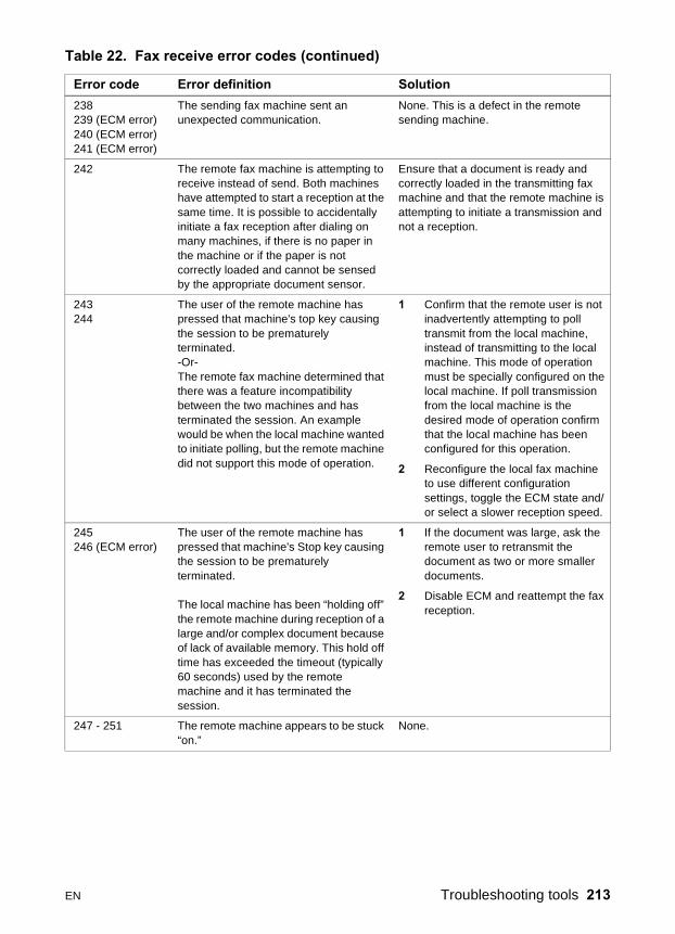
238239 (ECM error)240 (ECM error)241 (ECM error)
The sending fax machine sent an unexpected communication.
None. This is a defect in the remote sending machine.
242 The remote fax machine is attempting to receive instead of send. Both machines have attempted to start a reception at the same time. It is possible to accidentally initiate a fax reception after dialing on many machines, if there is no paper in the machine or if the paper is not correctly loaded and cannot be sensed by the appropriate document sensor.
Ensure that a document is ready and correctly loaded in the transmitting fax machine and that the remote machine is attempting to initiate a transmission and not a reception.
243244
The user of the remote machine has pressed that machine's top key causing the session to be prematurely terminated.-Or-The remote fax machine determined that there was a feature incompatibility between the two machines and has terminated the session. An example would be when the local machine wanted to initiate polling, but the remote machine did not support this mode of operation.
1 Confirm that the remote user is not inadvertently attempting to poll transmit from the local machine, instead of transmitting to the local machine. This mode of operation must be specially configured on the local machine. If poll transmission from the local machine is the desired mode of operation confirm that the local machine has been configured for this operation.
2 Reconfigure the local fax machine to use different configuration settings, toggle the ECM state and/or select a slower reception speed.
245246 (ECM error)
The user of the remote machine has pressed that machine's Stop key causing the session to be prematurely terminated.
The local machine has been “holding off” the remote machine during reception of a large and/or complex document because of lack of available memory. This hold off time has exceeded the timeout (typically 60 seconds) used by the remote machine and it has terminated the session.
1 If the document was large, ask the remote user to retransmit the document as two or more smaller documents.
2 Disable ECM and reattempt the fax reception.
247 - 251 The remote machine appears to be stuck “on.”
None.
Table 22. Fax receive error codes (continued)
Error code Error definition Solution
EN Troubleshooting tools 213

252 Telephone line conditions were too poor to receive a fax.
1 Reattempt the fax reception at a later time when line conditions may have improved.
2 Configure the machine to start reception at a lower speed.
3 If the local machine successfully received several pages of a larger document, ask the remote user to transmit the document in several smaller parts.
253 The remote machine has attempted to initiate a page transmission using a page width that is not supported by the local machine.
Ask the remote user to reconfigure their fax machine to transmit using a “normal” (letter/A4) page width.
281 The local machine has not received any data at the start of a page during non-ECM reception although the modem has not detected a remote disconnect. The remote machine is probably transmitting fill bytes instead of data and is either broken or jammed.
Reattempt the fax reception after first requesting that the remote user check his or her machine.
282 The local machine has not received any data at the start of a page during ECM reception although the modem has not detected a remote disconnect. The remote machine is probably transmitting sync frames instead of data and is either broken or jammed.
Reattempt the fax reception after first requesting that the remote user check his or her machine.
283 The local machine has detected that modem carrier has stopped. Either the line has been disconnected or the remote machine has aborted the transmission.
Reattempt the fax reception after first requesting that the remote user check his or her machine.
284 The local machine has not received any data during non-ECM page reception and a timeout failure has occurred. The remote machine is probably transmitting fill bytes instead of data and is either broken or jammed.
Reattempt the fax reception after first requesting that the remote user check his or her machine.
285 The local machine has stopped receiving any data during an ECM page reception although the modem has not detected a remote disconnect. The remote machine is probably transmitting sync frames instead of data and is either broken or jammed.
Reattempt the fax reception after first requesting that the remote user check his or her machine
Table 22. Fax receive error codes (continued)
Error code Error definition Solution
214 Chapter 6 - Troubleshooting EN

286 The remote machine has transmitted invalid data. The local machine has received frames with errors during an ECM reception and requested retransmission of the failed frames. The data that is resent does not correspond to the data that was requested. This is an implementation error from the remote machine.
Disable ECM and reattempt the reception.
290 The remote machine has attempted to renegotiate the session mode from ECM to non-ECM between pages. This operation is not supported, and the session has been abandoned.
Reattempt the fax reception and split the document into two portions correspond-ing to the ECM and non-ECM portions. Some machines will attempt to use non-ECM for photo mode, so this may be associated with a between page encoding change to support photo mode.
291 This isn't a communication error, and it is not expected that this error will occur under non-development scenarios. Reception has failed because the local unit is unable to open a file to receive data into. May be associated with low memory, although low memory should not, by itself, produce the error.
If the error persists, cycle the power on the unit.
292 The remote machine has attempted to renegotiate the encoding mode from non-JPEG to JPEG. This operation is not supported, and the session has been abandoned.
Reattempt the fax reception and split the document into two portions correspond-ing to the JPEG and non-JPEG portions. Some machines will attempt to use JPEG for photo mode, so this may be associated with a between page encoding change to support photo mode.
Table 22. Fax receive error codes (continued)
Error code Error definition Solution
EN Troubleshooting tools 215

Table 23. Fax send error codes
Error code Error condition Solution300 Fax session has completed without
errors.None required.
311 The user of the local machine has pressed the Stop key causing the session to be prematurely halted before all pages have been transmitted.
None required.
312 A remote fax device has failed to answer the call. Specifically fax tones or the fax handshake from a remote machine has not been detected. Typically this is caused by the user calling the wrong number, the correct number has been called but the machine has been configured not to answer, or the remote machine has temporarily disabled answering because of a condition such as lack of paper or a paper jam.
Confirm the remote fax machine is ready to receive a document and reattempt the transmission.
313 A busy signal has been detected each time the local machine has attempted to call the remote machine.
Reattempt the fax transmission at a later time when the line is no longer busy.
314 The local machine has attempted to initiate a remote diagnostic session but has detected that remote diagnostics are disabled at the remote machine.
Enable remote diagnostics on the remote machine.
315 The local machine has attempted to initiate a remote diagnostic session but has detected that the remote diagnostic version supported by the remote machine is incompatible.
No solution. Remote diagnostics cannot occur between machines with incompatible remote versions.
316 The local machine is set up to initiate document transmission, but it has detected that the remote machine is not able to receive a document. This error should be very rare since normally a remote machine will not answer if it cannot receive a document. One of the few exceptions to this would occur if the remote machine were configured to poll transmit a document but were unable to receive.
Configure the remote machine for reception. Typically the remote user configure the remote machine, including loading paper, clearing jams, and clearing other system abnormalities.
317 The remote machine cannot support a fax reception at any speed or modulation that is supported by the local machine.
None
318 The remote machine cannot support a fax reception at the page width selected by the local machine.
None
216 Chapter 6 - Troubleshooting EN

319 The local machine has attempted to initiate a binary file transfer (BFT) but has detected that the remote machine does not support this mode of operation.
1 Enable the BFT capability on the remote machine if it is supported.
2 Retransmit the document as a normal fax, rather than attempting a BFT transfer.
320 The local machine is set up to initiate poll reception with a remote machine, but it has detected that the remote machine is not configured to do this. Poll transmission from a remote machine is typically configured on a session-by-session basis.
Confirm that the local user really wants to attempt a poll reception. If not, reconfigure the local machine for a normal fax transmission. -Or-Configure the remote machine for poll transmission. The remote user must load a document to transmit and then configure the machine for polling.
321 There was a communication error with the receiving fax machine caused by poor telephone line conditions.
Reattempt the fax transmission at a different time when telephone line conditions have improved.
322 - 324 Telephone line conditions were too poor to send a fax.
1 Reattempt the fax transmission at a different time when telephone line conditions have improved.
2 If the session fails after transmitting several pages of a large document, retransmit the document as several smaller documents.
325 - 328 (ECM error)
Telephone line conditions were very poor.
Reattempt the fax transmission at a different time when telephone line conditions have improved.-Or-Disable ECM. Errors may still occur, and may result in a degraded image quality on the received page. However, the ability to transmit the entire document will be improved.
329 - 331 The remote machine has reported that one or more pages have been received (non-ECM mode) with excessive errors. This error does not result in the session being terminated immediately. Subsequent page transmission can still occur and later pages may be received without error.
Reattempt the fax transmission at a different time when telephone line conditions have improved.-Or-Select a lower speed for the initial transmission speed.
332 - 343 There is a defect in the remote fax machine (the other machine) and there is no solution except to send or receive to or from another fax machine.
Table 23. Fax send error codes (continued)
Error code Error condition Solution
EN Troubleshooting tools 217

344 - 348349-353 (ECM error)354-355
The remote machine has failed to respond to a fax command from the local machine because the connection is interrupted.-Or-The remote user has pressed the Stop key while the reception was in progress-Or-Under rare conditions, incompatibility between the two machines may cause the remote machine to simply abandon the call.
1 Reattempt the fax transmission at a different time when telephone line conditions have improved.
2 If the fax session was using error correction, disable ECM.
356 - 361362-366 (ECM error)
The remote user has pressed the Stop key causing the session to be aborted.-Or-The remote machine has encountered a system problem such as no paper or a paper jam which has inhibited it from receiving any more pages, and which has caused it to terminate the session prematurely.-Or-A feature incompatibility has been encountered by the remote machine causing it to terminate the session.
1 Configure the remote machine for document reception by clearing any paper jams, loading sufficient paper, and clearing any other system errors.
2 Configure the local fax machine to use different configurations; toggle the ECM state; select a slower reception speed.
367 - 372373-377 (ECM error)378-379
The remote machine appears to be stuck “on.”
None.
380 The remote machine has failed to issue a valid response to a CTC frame. This occurs during ECM transmission after multiple retransmissions of erroneous data.
None; there is a defect in the remote machine.
381 The remote machine has failed to respond to a fax command from the local machine because the connection is interrupted.-Or-The remote user has pressed the Stop key while the reception was in progress.
1 Reattempt the fax transmission at a different time when telephone line conditions have improved.
2 Disable ECM.
382 The remote fax machine has been “holding off” the local fax machine from continuing the ongoing transmission because of a temporary low memory condition at the remote machine. If this “hold off” period exceeds a machine's specific timeout value, the session will be terminated.
Resend the document as two or more separate fax transmissions. Wait several minutes between the end of one transmission and the start of the next transmission.-Or-Disable ECM.
Table 23. Fax send error codes (continued)
Error code Error condition Solution
218 Chapter 6 - Troubleshooting EN

383 The remote machine has failed to respond to a fax command from the local machine because the connection is interrupted.-Or-The remote user has pressed the Stop key while the reception was in progress.
Reattempt the fax transmission at a different time when telephone line conditions have improved-Or-Disable ECM.
384 The local machine has attempted a black JPEG transmission to a machine that does not support this mode.
Reattempt the fax transmission using a different mode.
386 The local machine has failed to complete phase 3 of the initial V.34 handshake after originating a fax session. This is usually caused by poor line conditions although it may be a compatibility issue with certain machines and/or line conditions.
1 Reattempt the fax reception at a different time when telephone line conditions have improved.
2 Disable V.34 on the local machine and attempt the transmission using the V.17 mode.
387 The local machine has failed to successfully negotiate the initial V.8 handshake with the remote machine after originating a fax session. Typically, this will occur when the remote machine is not fax-capable or has disabled reception. It may also be a compatibility issue with certain machines and/or line conditions.
1 Reattempt the fax transmission at a different time when telephone line conditions have improved.
2 Disable V.34 on the local machine and attempt the transmission using the V.17 mode.
388 The local machine has originated a fax session and detected a remote fax machine but has been unable to detect any T30 frames. If the machine is in V.17 mode it is likely that the connection has been interrupted. In V.34 mode, it is also possible for this error to occur because of compatibility problems with certain machines and/or line conditions.
1 Reattempt the fax transmission at a different time when telephone line conditions have improved.
2 Disable V.34 on the local machine and attempt the transmission using the V.17 mode.
389 The local machine has originated a fax session and has reattempted V.8 negotiations multiple times without success.
1 Reattempt the fax transmission at a different time when telephone line conditions have improved.
2 Disable V.34 on the local machine and attempt the transmission using the V.17 mode.
Table 23. Fax send error codes (continued)
Error code Error condition Solution
EN Troubleshooting tools 219

390 The local machine has originated a fax session using error correction (either V.34 or V.17). Transmission of an image has been abandoned after a timeout when no data has become ready for transmission. This is most likely caused by a low-memory condition, although it could be caused by other internal problems that cause generation of data for transmission to stall.
Reattempt the transmission after making sure documents stored in memory are printed, and the unit has paper ready for printing. If the problem persists, reinitialize permanent storage.
391 The local machine has originated a fax session without error correction (not V.34). Transmission of an image has been abandoned after a timeout when no data has become ready for transmission. This is most likely caused by a low memory condition although it could be caused by other internal problems that cause generation of data for transmission to stall.
Reattempt the transmission after making sure documents stored in memory are printed, and the unit has paper ready for printing. If the problem persists, reinitialize permanent storage.
392 The local machine has answered a fax session and completed the initial V.34 handshake but has been unable to detect any T30 frames. This failure is either compatibility problems with certain machines or is caused by line conditions.
1 Reattempt the fax reception at a different time when telephone line conditions have improved.
2 Disable V.34 on the local machine and attempt the reception using the V.17 mode.
393 The local machine has failed to complete phase 3 of the initial V.34 handshake after answering a fax session. This is usually caused by poor line conditions although it may be a compatibility issue with certain machines and/or line conditions.
1 Reattempt the fax reception at a different time when telephone line conditions have improved.
2 Disable V.34 on the local machine and attempt the reception using the V.17 mode.
394 The local machine has failed to successfully negotiate the initial V.8 handshake with the remote machine after answering a fax session. Typically, this will occur when the calling machine is not fax-capable. It may also be a compatibility issue with certain machines and/or line conditions.
1 Reattempt the fax reception at a different time when telephone line conditions have improved.
2 Disable V.34 on the local machine and attempt the reception using the V.17 mode.
395 An unexpected T.30 frame has been received between pages during a multi-page V.34 reception. This is almost certainly a compatibility problem with the remote machine and may be caused by an error with the implementation of the remote machine.
1 Reattempt the fax reception. If transmission errors are not encountered because line conditions have improved then this error will probably be avoided.
2 Disable V.34 on the local machine and attempt the reception using the V.17 mode.
Table 23. Fax send error codes (continued)
Error code Error condition Solution
220 Chapter 6 - Troubleshooting EN
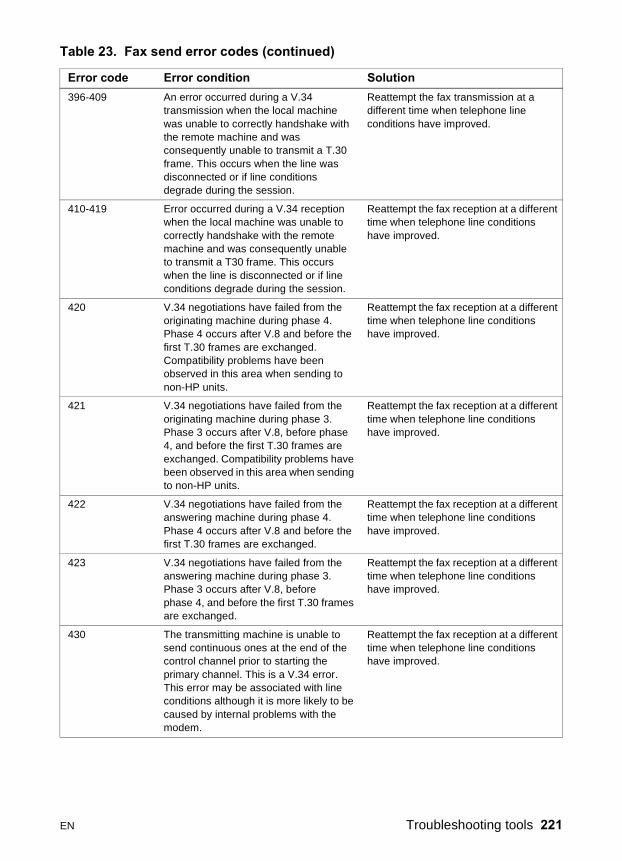
396-409 An error occurred during a V.34 transmission when the local machine was unable to correctly handshake with the remote machine and was consequently unable to transmit a T.30 frame. This occurs when the line was disconnected or if line conditions degrade during the session.
Reattempt the fax transmission at a different time when telephone line conditions have improved.
410-419 Error occurred during a V.34 reception when the local machine was unable to correctly handshake with the remote machine and was consequently unable to transmit a T30 frame. This occurs when the line is disconnected or if line conditions degrade during the session.
Reattempt the fax reception at a different time when telephone line conditions have improved.
420 V.34 negotiations have failed from the originating machine during phase 4. Phase 4 occurs after V.8 and before the first T.30 frames are exchanged. Compatibility problems have been observed in this area when sending to non-HP units.
Reattempt the fax reception at a different time when telephone line conditions have improved.
421 V.34 negotiations have failed from the originating machine during phase 3. Phase 3 occurs after V.8, before phase 4, and before the first T.30 frames are exchanged. Compatibility problems have been observed in this area when sending to non-HP units.
Reattempt the fax reception at a different time when telephone line conditions have improved.
422 V.34 negotiations have failed from the answering machine during phase 4. Phase 4 occurs after V.8 and before the first T.30 frames are exchanged.
Reattempt the fax reception at a different time when telephone line conditions have improved.
423 V.34 negotiations have failed from the answering machine during phase 3. Phase 3 occurs after V.8, before phase 4, and before the first T.30 frames are exchanged.
Reattempt the fax reception at a different time when telephone line conditions have improved.
430 The transmitting machine is unable to send continuous ones at the end of the control channel prior to starting the primary channel. This is a V.34 error. This error may be associated with line conditions although it is more likely to be caused by internal problems with the modem.
Reattempt the fax reception at a different time when telephone line conditions have improved.
Table 23. Fax send error codes (continued)
Error code Error condition Solution
EN Troubleshooting tools 221

Translating the fax trace reportPrint a fax log report (see the user guide for instructions). The fax log report contains information about the product’s interpretation of the problem.
Read the time sequences, looking for abnormal activity on the fax trace report. See table 24, “Fax phase sequence,” on page 223, and table 25, “Appropriate responses,” on page 224, to separate normal from abnormal activity. Fax abbreviations appear in table 26 on page 225.
Identify the phase in which the error occurred.
Note ??? is an unidentified command.
Examples of a successfully sent fax and a successfully received fax appear after the tables.
431 The transmitting machine has not received a response after aborting a transmission. Depending upon when the session is aborted, some remote machines may not respond. It should be noted that the local unit always attempts to abort the session in such a way that the remote machine is allowed to respond to the final PPS_EOP.
No action required. The session was aborted.
440-444 Error occurred during a V.34 transmission after one or more partial pages (image data) were transmitted using the primary channel. The transmitting machine was unable to restart the control channel in order to resume the T.30 handshake. This typically occurs when the receiving machine prematurely disconnects during partial page reception, although it is possible it may also be caused by compatibility issues.
Reattempt the fax reception at a different time when telephone line conditions have improved.
Table 23. Fax send error codes (continued)
Error code Error condition Solution
222 Chapter 6 - Troubleshooting EN
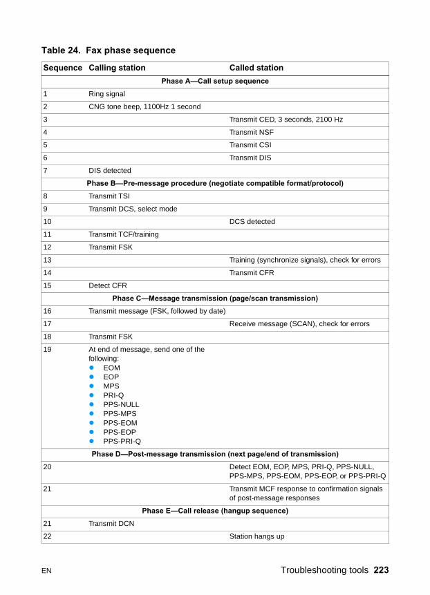
Table 24. Fax phase sequence
Sequence Calling station Called stationPhase A—Call setup sequence
1 Ring signal
2 CNG tone beep, 1100Hz 1 second
3 Transmit CED, 3 seconds, 2100 Hz
4 Transmit NSF
5 Transmit CSI
6 Transmit DIS
7 DIS detected
Phase B—Pre-message procedure (negotiate compatible format/protocol)8 Transmit TSI
9 Transmit DCS, select mode
10 DCS detected
11 Transmit TCF/training
12 Transmit FSK
13 Training (synchronize signals), check for errors
14 Transmit CFR
15 Detect CFR
Phase C—Message transmission (page/scan transmission)16 Transmit message (FSK, followed by date)
17 Receive message (SCAN), check for errors
18 Transmit FSK
19 At end of message, send one of the following:� EOM� EOP� MPS� PRI-Q� PPS-NULL� PPS-MPS� PPS-EOM� PPS-EOP� PPS-PRI-Q
Phase D—Post-message transmission (next page/end of transmission)20 Detect EOM, EOP, MPS, PRI-Q, PPS-NULL,
PPS-MPS, PPS-EOM, PPS-EOP, or PPS-PRI-Q
21 Transmit MCF response to confirmation signals of post-message responses
Phase E—Call release (hangup sequence)21 Transmit DCN
22 Station hangs up
EN Troubleshooting tools 223

Table 25. Appropriate responses
Commands Comments Appropriate responses(NSF) (CSI) DIS Identifying capabilities: from a manual receiver
or an auto-answer unit(NSC) (CIG) DTC(TSI) DCS(NSF) (CSI) DIS(CRP) (TSI) (NSS)(PWD) (SEP) (CIG) DTC(PWD) (SUB) (TSI) DCS
(NSC) (CIG) DTC Mode-setting command: from calling unit (TSI) DCS(NSF) (CSI) DIS
(PWD) (SEP) (CIG) DTC Poll operation (CRP) (TSI) (NSS)
(TSI) DCS(TSI) (NSS)
Mode-setting command: from manual transmitter or automatic receiver
CFRFTT(NSC) (CIG) DTC
(PWD (SUB) (TSI) DCS This command is always followed by phasing/training.
(NSC) (CIG) DTC
CTC Mode-setting command: from the transmitter to the receiver
(CTR)(CRP)
(EOR-NULL) Indicates the next block transmission from the transmitter to the receiver
(ERR)(RNR)(CRP)
Any one of the following:� (EOR-EOP)� (EOR-EOM)� (EOR-PRI-MPS)� (EOR-PRI-EOP)� (EOR-PRI-EOM)
The receiver (ERR)(RNR)PIN(CRP)
Any one of the following:� MPS� EOP� EOM� (PRI-MPS)� (PRI-EOP)� (PRI-EOM)
Post-message commands MCFRTPRTNPIPPIN(CRP)
(PPS-NULL) Post-message command for a partial page from the transmitter to the receiver
(PPR)MCF(RNR)(CRP)
Any one of the following:� (PPS-MPS)� (PPS-EOP)� (PPS-EOM)� (PPS-PRI-MPS)� (PPS-PRI-EOP)� (PPS-PRI-EOM)
Post-message commands for a complete page from the transmitter to the receiver
(PPR)MCF(RNR)PIPPIN(CRP)
(RR) Ask for the status of the receiver: from the transmitter to the receiver
(RNR)(ERR)MCFPIPPIN(CRP)
DCN Phase E command None
224 Chapter 6 - Troubleshooting EN

Table 26. Fax abbreviations
Abbreviation Function Signal format (“X”= any #)CED Called station identification 2100 Hz
CFR Confirmation to receive X010 0001 1850 or 1650 Hz for 3 seconds
CIG Calling subscriber identification 1000 0010
CNG Calling tone 1100 Hz for 500 ms
CRP Command repeat X101 1000
CSI Called subscriber identification 0000 0010
CTC Continue to correct X100 1000
CTR Response to continue to correct X010 0011
DBM -dBM signal strength detected from sending station (number is deviation from average value)
Range in -10 to -43 (-43 is a weak signal; see explanation below Figure 85, Example of a successfully received fax)
DCN Disconnect X101 1111
DCS Digital command signal X100 0001
DIS Digital identification signal 0000 0001
DTC Digital transmit command 1000 0001
DOM End of message X111 0001 1100 Hz
EOP End of procedure X111 0100
EOR End of retransmission X111 0011
EQM Eye quality monitor—a measure of the modem signal quality, lower numbers indicate better signals
0-99
ERR Response for end of retransmission X011 1000
ECD Facsimile coded date 0110 0000
FCF Facsimile
FCS Frame check sequence
FDM File diagnostics message X011 1111
FIF Facsimile information field
FSK Frequency shift key. Low-speed command identifier separating commands/scans; precedes command mode.
FTT Failure to train. The 1.5 seconds of the Training Check Frame (TCF) indicates line conditions are not good enough for this modulation.
X010 0010
GC Group command 1300 Hz for 1.5 to 100 seconds2100 Hz for 1.5 to 100 seconds
GI Group identification 1650 or 1850 Hz
HDLC High-level data link control
LCS Line conditioning signals 1100 Hz
EN Troubleshooting tools 225
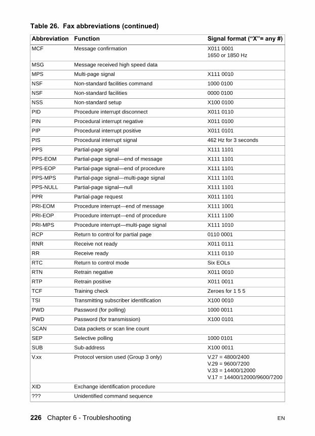
MCF Message confirmation X011 00011650 or 1850 Hz
MSG Message received high speed data
MPS Multi-page signal X111 0010
NSF Non-standard facilities command 1000 0100
NSF Non-standard facilities 0000 0100
NSS Non-standard setup X100 0100
PID Procedure interrupt disconnect X011 0110
PIN Procedural interrupt negative X011 0100
PIP Procedural interrupt positive X011 0101
PIS Procedural interrupt signal 462 Hz for 3 seconds
PPS Partial-page signal X111 1101
PPS-EOM Partial-page signal—end of message X111 1101
PPS-EOP Partial-page signal—end of procedure X111 1101
PPS-MPS Partial-page signal—multi-page signal X111 1101
PPS-NULL Partial-page signal—null X111 1101
PPR Partial-page request X011 1101
PRI-EOM Procedure interrupt—end of message X111 1001
PRI-EOP Procedure interrupt—end of procedure X111 1100
PRI-MPS Procedure interrupt—multi-page signal X111 1010
RCP Return to control for partial page 0110 0001
RNR Receive not ready X011 0111
RR Receive ready X111 0110
RTC Return to control mode Six EOLs
RTN Retrain negative X011 0010
RTP Retrain positive X011 0011
TCF Training check Zeroes for 1 5 5
TSI Transmitting subscriber identification X100 0010
PWD Password (for polling) 1000 0011
PWD Password (for transmission) X100 0101
SCAN Data packets or scan line count
SEP Selective polling 1000 0101
SUB Sub-address X100 0011
V.xx Protocol version used (Group 3 only) V.27 = 4800/2400V.29 = 9600/7200V.33 = 14400/12000V.17 = 14400/12000/9600/7200
XID Exchange identification procedure
??? Unidentified command sequence
Table 26. Fax abbreviations (continued)
Abbreviation Function Signal format (“X”= any #)
226 Chapter 6 - Troubleshooting EN

Figure 102. Example of a T.30 trace of a successfully sent fax
Note Phase A, call establishment, does not show up on a trace report. Phase C is the phase in which faxed pages are transferred.
EN Troubleshooting tools 227
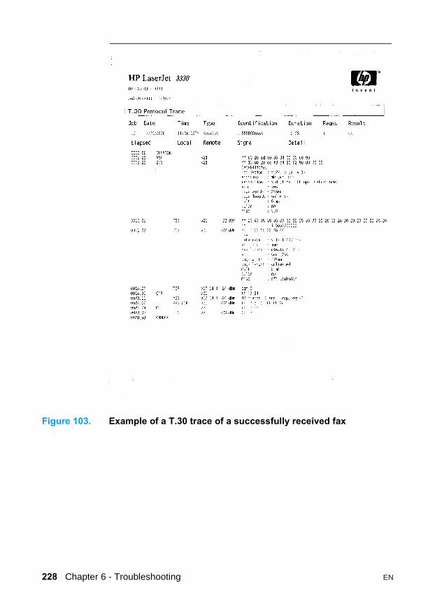
Figure 103. Example of a T.30 trace of a successfully received fax
228 Chapter 6 - Troubleshooting EN

Service mode functions
Secondary service menuUse the secondary service menu to perform various tests and print service reports. Below is a hierarchical diagram of the secondary service menu:
To gain access to the secondary service menu1 Make sure that the control panel display reads Ready.
2 Press menu/enter.
3 Press 2 on the keypad.
Note You can access the secondary service menu from any other menu by pressing 2.
4 Use the < and > keys to navigate the secondary service menu.
5 To exit the secondary service menu and remove it from the menu tree, press cancel to return to the Ready display, then press cancel again.
To print a list of all the data store parameters1 From the secondary service menu, use the < and > keys to select
Service reports, and press menu/enter.
2 Use the < and > keys to select Data Store, and press menu/enter.
Main menu Submenu Submenu2ndary Service ............. Service reports............ Continuous Self-Test
Data StoreExtended Keymap
Scanline data ............... Red-correctedBlue-correctedGreen-correctedRed-uncorrectedBlue-uncorrectedGreen-uncorrected
EN Service mode functions 229

Developer’s menuUse the developer’s menu to adjust fax data store parameters and to run various tests. Below is a hierarchical diagram of the developer’s menu:
To gain access to the developer’s menu:1 Make sure that the control panel display reads Ready.
2 Press menu/enter.
3 Press the * and # keys on the keypad.
Note You can access the developer’s menu from any other menu by pressing the * and # keys on the keypad.
4 Use the < and > keys to navigate the developer’s menu.
5 To exit the developer’s menu and remove it from the menu tree, press cancel to return to the Ready display, then press cancel again.
Main menu Submenu SubmenuDeveloper’s menu ............ R/W parameter
Monitor test ...................... Onhook monitorOffhook monitorEavesdrop monitorSignal power monitor
LIU test ............................. LIU inputsLIU ID
Loopback test
Transmit test
230 Chapter 6 - Troubleshooting EN

To adjust a country/region code parameterFax data store parameter number 3 is LIU COUNTRY, which is the country/region code for the fax. Before adjusting the fax data store parameters, you can print a list of all the parameters from the secondary service menu (page 229).
Note Changing the country/region code does not change the language.
1 Use the < and > keys to navigate to R/W PARAMETER and then press menu/enter.
2 Press >>> to display LIU COUNTRY, then press menu/enter.
3 Use the keypad to input the country/region code (see table 27below) and then press menu/enter.
Note As a shortcut, you can press 3 at the R/W PARAMETER menu to move to directly to parameter 3. However, this shortcut has restrictions associated with parameters containing the number 2. (See page 232 for more information about this shortcut.)
CAUTION Changing country/region code parameters can render the productillegal or inoperable.
Table 27. Country/region codes
Country/region Country/region code Country/region Country/region code
Argentina 16 Malaysia 27
Australia 23 Mexico 13
Austria 34 Netherlands 35
Belgium 45 New Zealand 19
Canada 14 Norway 43
China 6 Poland 56
Denmark 40 Portugal 50
Finland 46 Russia 64
France 47 Singapore 30
Germany 39 Spain 55
Greece 49 Sweden 41
Hong Kong 29 Switzerland 36
Hungary 62 Taiwan 7
EN Service mode functions 231

4 Power-cycle the product by unplugging (or turning off) the product and then plugging back in (or turning on) the product.
To adjust fax data store parameters
CAUTION When you adjust fax data store parameters, the product does not alert you to incorrect input values. Changing fax data store parameters can render the product illegal or inoperable.
Note Before adjusting the fax data store parameters, you can print a list of all the parameters from the secondary service menu (page 229).
1 On the developer’s menu, use the < and > keys to navigate toR/W PARAMETER and then press menu/enter.
2 Use the < and > keys to locate the parameter you want to change. The control panel display shows the current setting.
3 Enter the new value for the fax data store parameter and then press menu/enter.
To scroll quickly to a particular data store parameterWhen the display says R/W PARAMETER, you can jump directly to any parameter ID that does not contain a 2 by entering the ID on the keypad. If you press 2, that will bring up the secondary service menu. If you want to change a parameter that has a 2 in its ID, enter the ID of the closest parameter that does not have a 2 and then use the < and > keys to locate the parameter you want to change. For example, to move quickly to parameter 152, enter 151 >.
Ireland 44 Ukraine 63
Israel 21 United Kingdom 31
Italy 51 United States 15
Korea 4
Table 27. Country/region codes
Country/region Country/region code Country/region Country/region code
232 Chapter 6 - Troubleshooting EN
NVRAM initNVRAM init sets all stored parameters in NVRAM back to factory default values or to a default ROM value, depending on the variable, and performs a system reset.
CAUTION Performing NVRAM init can cause the product to violate local telephone regulations. Reset the language and country/regioncode after performing NVRAM init.
NVRAM init resets the following:
� All menu settings to factory default values, including fax header and company name
� Factory settings such as formatter number, page counts, and factory paper settings
� Fax memory—all faxes in memory are erased
To perform NVRAM init1 Unplug (or turn off) the product from the power source.
2 Press and hold down the * and menu/enter keys.
3 Continue to hold down the keys while you plug back in (or turn on) the product, through the entire power on sequence.
4 When the control panel display reads Permanent StorageInit. release the keys.
5 Allow the product to return to Ready before using the product.
PJL software commandsYou can use PJL software commands to set the following NVRAM variables:
Factory printer DEFAULT PAPER, scanner factory default paper size will be set to the same value automatically.
Factory printer DEFAULT LPARM:PCL SYMSET
Factory DEFAULT OEM bit
Factory DEFAULT PRINTPAGECOUNT
Factory DEFAULT SCANPAGECOUNT
Factory DEFAULT COPYPAGECOUNT
� All localization settings, including language and country/region code
EN Service mode functions 233

The table below provides a more detailed description of the NVRAM PJL factory variables and commands and shows possible settings for each.
Figure 104. NVRAM PJL factory variables
To use these commands, you need some method to send PJL commands to the product, either with a software tool or by copying a file that contains the commands from the host using a DOS box. For example, from the DOS prompt:
copy /b filename lpt1
Here is an example of a file that uses one of the commands:
ESC%-12345X@PJL SET SERVICEMODE=HPBOISEID
@PJL ‘command’
@PJL RESET
Here is an example of using the NVRAMINIT command:
ESC%-12345X@PJL SET SERVICEMODE=HPBOISEID
@PJL NVRAMINIT
@PJL RESET
NVRAM PJL Variable or Command Possible settingsDEFAULT PAPER "LETTER", "LEGAL, "A4",
"EXECUTIVE”, "COM10”,"MONARCH”, "DL”, "C5”, "B5","CUSTOM"
DEFAULT LPARM:PCL SYMSET "ROMAN8", "ISOL1", "ISOL2","ISOL5", "PC8", "PC8DN", "PC850","PC852", "PC8TK", "WINL1","WINL2", "WINL5", "DESKTOP","PSTEXT", "VNINTL", "VNUS","MSPUBL", "MATH8", "PSMATH","VNMATH", "PIFONT", "LEGAL","ISO4", "ISO6", "ISO11", "ISO15","ISO17", "ISO21", "ISO60", "ISO69","WIN30"
DEFAULT OEM “ON”, “OFF”
DEFAULT PRINTPAGECOUNT 0-2147483647
DEFAULT SCANPAGECOUNT 0-2147483647
DEFAULT COPYPAGECOUNT 0-2147483647
CLEARNVRAM None - Command
NVRAMINIT None - Command
234 Chapter 6 - Troubleshooting EN

Note Set SERVICEMODE before trying to set the variable or you will not get the desired result. Also reset the PJL to be sure the SERVICEMODE status is cleared.
To create these files, you need a text editor that can insert the ESC character or is able to copy it from an existing file. If a software tool is used, simply send the same strings in the same order as given for the example files.
EN Service mode functions 235

Repetitive image defect ruler
Figure 105. Repetitive image defect ruler
First occurrence of print defect
Toner/developing cylinder (37.7 mm)Toner/primary charging roller (37.7 mm)
Heating element (56.5 mm)
Transfer roller (45.2 mm)
Pressure roller (62.8 mm)
Toner/drum (75.4 mm)
236 Chapter 6 - Troubleshooting EN

Main wiring
Figure 106. Main wiring (1 of 2)
EN Main wiring 237
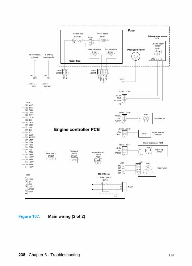
Figure 107. Main wiring (2 of 2)
238 Chapter 6 - Troubleshooting EN
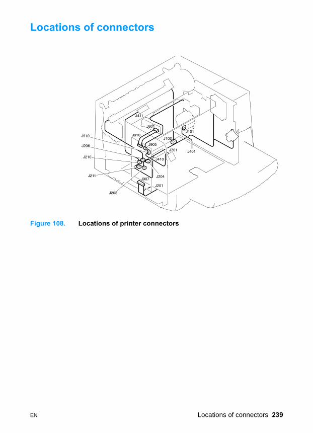
Locations of connectors
Figure 108. Locations of printer connectors
EN Locations of connectors 239

Locations of connectors and switches
Figure 109. Locations of connectors and switches
Table 28. Switch functions
SW number Function Remarks
SW101 Power switch 220-240V only
SW201 Switch for test print
SW301 Switch for detection of open door
240 Chapter 6 - Troubleshooting EN