basics of design: flexible continuous- - igus® plastics … · some manufacturers make...
TRANSCRIPT

1
Here we outline the features of continuous-flex cables and how to organize them to work best in dynamic applications.
Continuous-flex cables last longer and work better than conventional cable in auto-mated machinery for control, data, bus, position feedback, fiber optic, coaxial, servo, power, and robot applications.
Continuous-flex cables are typically used in conjunction with cable carriers — plastic articulating trays to support and guide cables through motion — or come in pre-harnessed systems in which connectors are already attached to the cables, and the cables are installed and separated in the correct order within a cable carrier.
BASICS OF DESIGN:Flexible Continuous-Flex Cables
CONTENTS
Continuous- flex cable stranding … 1
Continuous- flex cable shielding … 2
Continuous- flex cable jackets … 3
Cable management … 4
Presented by
But what makes continu-ous-flex cables different? De-veloped in the 1980s, contin-uous-flex cable incorporates features to prevent corkscrews, conductor breakage, and other problems. (Corkscrewing refers to the permanent deforma-tion of moved cables caused by excessive stressing. The end result is usually conductor breakage, cable failure, and machine downtime.) In fact, several design features make for continuous-flex cable that performs in applications and withstands millions of flexing cycles in demanding environ-ments.
Continuous-flex cable stranding
Continuous-flex cables are stranded in bundles, not layers. Stranding in layers is signifi-cantly easier to produce and so
Sponsored by

Some manufacturers make continuous-flex cables with bundled conductors to eliminate problems. The wires are twisted with a special pitch length and then the conductors are bundled.
The multiple bundling of the conductors changes the inner radius and outer radius of the bent cable several times at identical intervals as it flexes. Pulling and compressive forces balance one another around the high tensile strength core and that provides inner stability — so the cable structure stays stable even under maximum bending stress.
machine downtime. Flexible cables constructed in layers are relatively cheap to produce, but are prone to corkscrewing. Such cables are often constructed without attention to pitch length or direction, and typically have fleece wraps and binders with a tube-extruded jacket.
Corkscrewing is the permanent deformation of flexing cables in automated applications caused by excessive stress. It results in conductor ruptures, cable failure, and
2
Cabl
e
man
agem
ent …
4Co
ntin
uous
-flex
cab
le
jack
ets
… 3
Co
ntin
uous
-flex
cab
le
shie
ldin
g …
2Co
ntin
uous
-flex
cab
le
stra
ndin
g …
1
compressing forces of bending motion balance and cancel any torsion — and all conductors move at identically spaced distances for both inner and outer radii.
Copper stranding with a medium to fine strand diameter is often preferable. (Traditional flexing cable employs extra-fine conductor strand that can kink under high duty cycles.) In fact, some manufacturers use a combination of single-wire diameter, pitch length, and pitch direction to optimize life performance for the most demanding applications.
Continuous-flex cable shieldingAnother feature of continuous-flex cable is its shield
design. Braided shield protects cables from external electro-magnetic interference (EMI) and contains internally gener-ated EMI before it’s transmitted outward. Both are important because faulty signals can significantly damage the machine and controls. Incorrect shielding usually cannot be detected from the outside, which makes trouble-shooting extremely difficult.
Although it’s easy to shield a static cable, it is much more
is common in ”cable-carrier-suitable” cable. As mentioned, such cable is prone to corkscrewing, which can eventually make the cables fail and immobilize whole machines.
Stranding in layers means cable conductors are cabled in relatively long lengths in several layers around center filler and then jacketed with extrusion to form a tube. Then (when shielded), the conductors are wrapped with fleece or foils.
Consider what happens to a 14-conductor cable con-structed like this during normal operation. Bending com-presses the cable’s inner radius and stretches the conductor at the outer radius. Initially, the elasticity of the material lets the cable return to its initial shape. However, material fatigue quickly causes permanent deformations. This causes the corkscrew effect, usually followed by conductor breakage and cable failure.
In contrast, continuous-flex cables have bundled cable designs that eliminates such problems. First the conduc-tors are cabled into bundles. For cables with greater than 12 conductors the pre-cables are then combined into a single layer around a strain-relief element. That way, pulling and

If a cable is not properly constructed, it can lead to cable failure in the form of corkscrewing and jacket rupture.Some basic cables provide sufficient physical support to conductors in short-travel applications but not in long-travel, gliding, or flexing applications. Here they tend to fatigue and their insulation and jacket compounds lose their tensile and elongation properties. This greatly reduces service life. As these materials break down, the flexible cable core is compromised and the torsional forces of the cabled conductors release and untwist in parts of the cable. This causes corkscrewing. The risk of such problems is increased with flexible cables having multiple layers (usually more than 12 conductors).
Insulation materials mustn’t adhere to one another within the cable but must support the stranded individual wires of the conductor. High-pressure-extruded PVC or TPE are suitable. Here, the outer jacket of a cable not designed for flexing failed, exposing conductors to wear and the high probability of eventual failure.
3
Cable m
anagement …
4Continuous-flex cable jackets …
3 Continuous-flex cable shielding …
2Continuous-flex cable stranding …
1
the linear axis and increase torsional stability — and have a gusset-filled extruded inner jacket goes over the cable struc-ture. As we’ll explore in the next section, this second jacket holds the cable structure together and guides the individual conductors, and it also serves as a firm, round base for a tight-fitting shield. The rugged shielding design has a braid angle that efficiently neutralizes tensile forces (because the shield it-self protects the cable structure from torsional forces) while an inner jacket prevents the shield from migrating or deforming.
Continuous-flex cable jacketsA cable’s outer jacket is its first line of defense against the
extreme and rugged conditions that exist in industrial applica-tions. The jacket material can and will crack, abrade, swell and become ineffective in protecting the inner components of the cable. To prevent jacket failure, designers should work with cable designers to select a suitable jacket from myriad materials. The outer jacket material must resist UV rays, abra-sion, and attack by oils and chemicals, but mustn’t adhere to anything and be flexible while providing support. The proper jacket material also needs to have a temperature range suited for the application environment.
It’s not just the material and outer jacket that count, though. With common cables, inner jacketing consists of inexpensive fleece wrap or filler, and outer jackets are usually extruded to form a tube, so don’t give the contained conduc-tors any support in constant-bending applications.
In contrast, some manufacturers offer continuous-flex
difficult to guarantee the permanent shielding of a moving cable. Typical cables use a combination of metallic tapes, braids and serves. The make up and design of these shield-ing materials are not conducive to continuous flexing. These materials when used in continuous flexing cables will quickly lose their effectiveness.
With an unsuitable braiding angle, tensile loads increase and can break the shield wire. Tapes develop pinholes and flake apart. Metallic braids and serves break and the broken strands can poke into conductor insulation causing electrical short circuit. Loose and open braid shields and even simple wire wrappings are also common shield options (despite their drawbacks). Here’s a rule of thumb to avoid the problem: Strip the jacket off a sample of cable. If you can easily push the shield back over the jacket, the shield is inappropriate for continuous-flex applications. Continuous-flexing shield de-sign is possible but attention needs to be taken for the thick-ness and hardness of the metallic tapes and more importantly the dimensional application of the metallic braid or served shield. The type of flex movement (whether it be linear or torsional) should also be considered when designing a cables shield component.
In contrast, some continuous-flex cables (including igus Chainflex cables) are shielded over 90% optically with braided tinned copper shields using strands that prevent breaking over
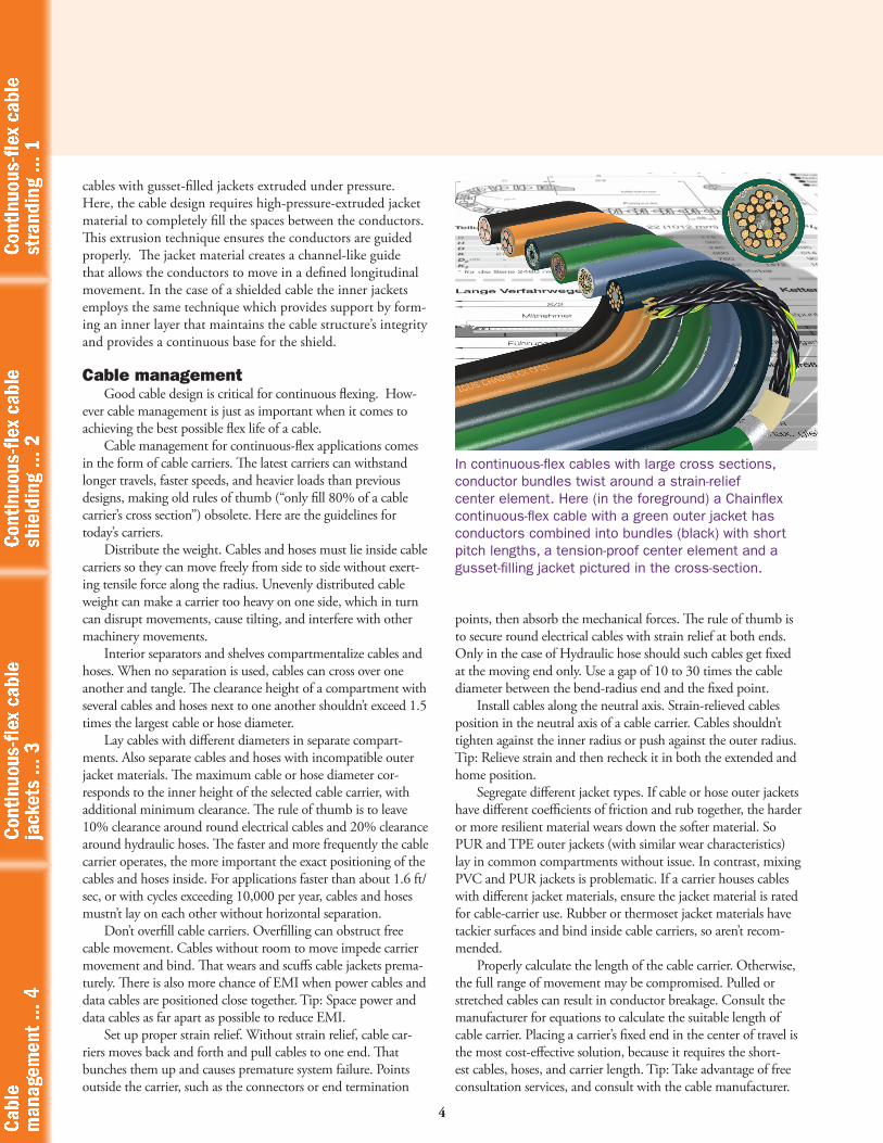
In continuous-flex cables with large cross sections, conductor bundles twist around a strain-relief center element. Here (in the foreground) a Chainflex continuous-flex cable with a green outer jacket has conductors combined into bundles (black) with short pitch lengths, a tension-proof center element and a gusset-filling jacket pictured in the cross-section.
4
points, then absorb the mechanical forces. The rule of thumb is to secure round electrical cables with strain relief at both ends. Only in the case of Hydraulic hose should such cables get fixed at the moving end only. Use a gap of 10 to 30 times the cable diameter between the bend-radius end and the fixed point.
Install cables along the neutral axis. Strain-relieved cables position in the neutral axis of a cable carrier. Cables shouldn’t tighten against the inner radius or push against the outer radius. Tip: Relieve strain and then recheck it in both the extended and home position.
Segregate different jacket types. If cable or hose outer jackets have different coefficients of friction and rub together, the harder or more resilient material wears down the softer material. So PUR and TPE outer jackets (with similar wear characteristics) lay in common compartments without issue. In contrast, mixing PVC and PUR jackets is problematic. If a carrier houses cables with different jacket materials, ensure the jacket material is rated for cable-carrier use. Rubber or thermoset jacket materials have tackier surfaces and bind inside cable carriers, so aren’t recom-mended.
Properly calculate the length of the cable carrier. Otherwise, the full range of movement may be compromised. Pulled or stretched cables can result in conductor breakage. Consult the manufacturer for equations to calculate the suitable length of cable carrier. Placing a carrier’s fixed end in the center of travel is the most cost-effective solution, because it requires the short-est cables, hoses, and carrier length. Tip: Take advantage of free consultation services, and consult with the cable manufacturer.
cables with gusset-filled jackets extruded under pressure. Here, the cable design requires high-pressure-extruded jacket material to completely fill the spaces between the conductors. This extrusion technique ensures the conductors are guided properly. The jacket material creates a channel-like guide that allows the conductors to move in a defined longitudinal movement. In the case of a shielded cable the inner jackets employs the same technique which provides support by form-ing an inner layer that maintains the cable structure’s integrity and provides a continuous base for the shield.
Cable managementGood cable design is critical for continuous flexing. How-
ever cable management is just as important when it comes to achieving the best possible flex life of a cable.
Cable management for continuous-flex applications comes in the form of cable carriers. The latest carriers can withstand longer travels, faster speeds, and heavier loads than previous designs, making old rules of thumb (“only fill 80% of a cable carrier’s cross section”) obsolete. Here are the guidelines for today’s carriers.
Distribute the weight. Cables and hoses must lie inside cable carriers so they can move freely from side to side without exert-ing tensile force along the radius. Unevenly distributed cable weight can make a carrier too heavy on one side, which in turn can disrupt movements, cause tilting, and interfere with other machinery movements.
Interior separators and shelves compartmentalize cables and hoses. When no separation is used, cables can cross over one another and tangle. The clearance height of a compartment with several cables and hoses next to one another shouldn’t exceed 1.5 times the largest cable or hose diameter.
Lay cables with different diameters in separate compart-ments. Also separate cables and hoses with incompatible outer jacket materials. The maximum cable or hose diameter cor-responds to the inner height of the selected cable carrier, with additional minimum clearance. The rule of thumb is to leave 10% clearance around round electrical cables and 20% clearance around hydraulic hoses. The faster and more frequently the cable carrier operates, the more important the exact positioning of the cables and hoses inside. For applications faster than about 1.6 ft/sec, or with cycles exceeding 10,000 per year, cables and hoses mustn’t lay on each other without horizontal separation.
Don’t overfill cable carriers. Overfilling can obstruct free cable movement. Cables without room to move impede carrier movement and bind. That wears and scuffs cable jackets prema-turely. There is also more chance of EMI when power cables and data cables are positioned close together. Tip: Space power and data cables as far apart as possible to reduce EMI.
Set up proper strain relief. Without strain relief, cable car-riers moves back and forth and pull cables to one end. That bunches them up and causes premature system failure. Points outside the carrier, such as the connectors or end termination
Cabl
e
man
agem
ent …
4Co
ntin
uous
-flex
cab
le
jack
ets
… 3
Co
ntin
uous
-flex
cab
le
shie
ldin
g …
2Co
ntin
uous
-flex
cab
le
stra
ndin
g …
1