basics of electrical machines
TRANSCRIPT

MODULE 5 EE100 Basics of Electrical Engineering
Page 1 of 19
MODULE 5
ELECTRICAL MACHINES
An electrical machine consumes electrical energy to do a specific work or it converts electrical
energy to other forms like mechanical energy, light energy, heat etc. In this module, we will
be discussing the principle, working, construction, application, merits and demerits of various
electrical machines used in our day to day life. The following are the various machines which
we will be dealing with:
Transformer
o Principle of Operation
o Construction
o EMF Equation and Transformation Ratio
o Losses in a Transformer
o Efficiency
DC Machines
o Construction
o Principle of Operation and Working of DC Motor
o Back EMF
o Voltage, Power and Torque of DC motor
o Necessity of a Starter
o Types of DC Motor
Three Phase Induction Motor
o Construction
o Principle of Operation
Single Phase Induction Motor
o Types of Single Phase Induction Motor
Universal Motor
Numerical Problems.

MODULE 5 EE100 Basics of Electrical Engineering
Page 2 of 19
1. TRANSFORMER
Transformer is a static AC machine (i.e it contains no moving parts) which is used to increase
or decrease the AC voltage without changing the frequency. It consist of 2 windings – primary
winding and secondary winding- which are wound on same magnetic core as shown below.
Simple representation of a transformer
1.1 Principle of Operation
The working principle of transformer is Faradays Laws of Electromagnetic Induction. The two
windings; primary and secondary, are electrically separated but wound on same magnetic core.
When AC voltage is applied to primary winding, it creates alternating magnetic flux (ϕm)
which links with the secondary winding. This alternating magnetic flux will induce an EMF in
the secondary winding. The magnitude of induced EMF in the secondary can be increased or
decreased by increasing or decreasing the number of turns.
The transformer which increases the voltage is called step up transformer.
For a step up transformer; N1<N2 and V1<V2
The transformer which decreases the voltage is called step down transformer
For a step down transformer; N1>N2 and V1>V2
Where N1 : Number of turns in primary winding
N2 : Number of turns in secondary winding
V1 : Voltage at primary winding
V2: Voltage at secondary winding

MODULE 5 EE100 Basics of Electrical Engineering
Page 3 of 19
1.2 Construction of a Transformer
The main parts of a transformer are:
Core : The core is made of laminated silicon steel. Each laminations have a thickness
of 0.35mm to 0.5mm and is coated with thin layer of varnish. Several number of such
laminations are pressed together to form the core. The function of core is to provide
low reluctance path to the magnetic flux. Based on the type of core, the transformer is
of two types : core type and shell type.
In core type transformer, the windings are wound on the side limbs of the core as
shown in figure below. In core type transformer the high voltage winding (HV) is
wound over the low voltage winding (LV).
Core type transformer
In shell type transformer, both the LV and HV windings are wound on the central
limb in sandwich pattern as shown below.
Shell type transformer

MODULE 5 EE100 Basics of Electrical Engineering
Page 4 of 19
Windings : These are made of enamelled copper wire. Each turn of the winding is
insulated from each other.
Transformer Tank : This tank stores the oil needed for cooling and insulation of
transformer. It is mounted on the top of the transformer.
Conservator Tank : This is a small tank connected to the main tank. This tank
accommodates the change is oil levels during the heating and cooling of transformer
oil.
Terminal Bushings : These are used to insulate the output terminals of the
transformer.
Breather : The breather provides the passage of air in to the transformer during
contraction of oil during cooling. The breather consist of silica gel, through which the
air is passed. The silica gel absorbs the moisture content in the air.
1.3 EMF Equation of Transformer
Let an alternating voltage V1 with frequency F be applied to primary winding of the transformer
as shown in figure above. Let the number of turns in the primary be N1. The alternating voltage
will set up a flux given by
Φ = Φm Sin ωt
Where; Φm is the maximum value of flux.
ω = 2πF
By Faradays Law, induced EMF, e1 = -N1 𝑑𝜙
𝑑𝑡

MODULE 5 EE100 Basics of Electrical Engineering
Page 5 of 19
e1 = -N1 𝑑
𝑑𝑡 (Φm Sin ωt)
i.e e1 = -N1 ω Φm cos ωt
= -N1 2πF Φm cos ωt
e1 = N1 2πF Φm sin (ωt – 90)
in the above equation e1 attains maximum value when sin (ωt – 90) = 1.Therefore the maximum
value E1 is given by
E1 = N1 2πF Φm
i.e E1 = 4.44 N1 F Φm
Similarly E2 = 4.44 N2 F Φm
1.4 Transformation Ratio
Transformation ratio, K = 𝑁2
𝑁1 =
𝑉2
𝑉1 =
𝐸2
𝐸1 =
𝐼1
𝐼2
1.5 Losses in a Transformer
The losses in a transformer are of two types :
(i) Core loss or Iron loss
(ii) Copper loss.
Core loss or iron loss is occurring due to alternating flux in the core. It mainly consist of eddy
current loss and hysteresis loss. The core loss or iron loss is constant for a transformer and does
not vary with load.
Eddy current loss is due to eddy current occurring in the core of transformer. The core is
laminated to reduce the eddy current loss. Eddy current loss is given by
Eddy current loss, Pe = QBm2f2t2V
Hysteresis loss is due to frequent reversal of magnetic flux in the core. It is given by
Hysteresis loss, Ph = PBm1.6fV
Where Q = constant
P = Hysteresis coefficient

MODULE 5 EE100 Basics of Electrical Engineering
Page 6 of 19
F = Frequency
V = Volume of core
t = Thickness of lamination
Iron loss = Eddy current loss + hysteresis loss
Pi = Pe + Ph
Copper loss is due to resistance of the winding. It is the I2R loss occurring in the winding of
transformer.
Total copper loss, Pc = copper loss in primary + copper loss in secondary
Pc = I12R1 + I2
2R2
Where I2 = secondary current
R2 = secondary winding resistance
I1 = primary current
R1 = primary winding resistance
TOTAL LOSS ON TRANSFOMER = CORE LOSS + COPPER LOSS
1.6 Efficiency of a Transformer
Efficiency = output power
input power
or
Efficiency = output power
output power + losses
Efficiency is maximum when core loss = copper loss.
Efficiency = kWh output in 24 hours
kWh input in 24 hours

MODULE 5 EE100 Basics of Electrical Engineering
Page 7 of 19
2. DC MACHINE
A transformer works on alternating current, while a DC machine works on Direct Current. A
DC machine can be a DC motor or a DC generator. It has two main parts :
Stator – It is the stationary part. It does not move or rotate.
Rotor – It is the rotating part of the machine.
2.1 Construction of a DC Machine
The mains parts of a DC machine are
Yoke : It is the outermost part of a DC motor or a DC generator. It is made of cast iron
or cast steel. It act as a supporting frame to hold the machine and to protect the machine
from mechanical injury. It also serves as the low reluctance path for the magnetic flux.
Poles : These are made of steel laminations. The main purpose is to hold the field
windings into position. The end portion of the pole is called pole shoe. The pole and
the field windings together act as an electromagnet.
Field Windings : They are enamelled copper wires wound around the poles. It consist
of several turns which are insulated from each other. When current passes through these
windings they form an electromagnet with alternate north and south poles.
Armature : This is the rotating part of the machine. It is a cylindrical structure with
slots around its outer periphery. Several turns of copper wire are wound through these
slots. When current is passed through the armature windings, it begins to rotate.
Commutator : The commutator is attached to the same shaft of the armature. It consist
of several copper segments insulated by mica. The armature winding is connected to
the commutator segments. The commutator converts DC to AC and AC to DC.
Brushes : The brushes are sliding contacts which are used to give and collect current
from the armature through the commutator.
The yoke, poles and field windings form the stator.
The armature and commutator forms the rotor.

MODULE 5 EE100 Basics of Electrical Engineering
Page 8 of 19
DC Machine
2.2 DC Motor
DC motor converts electrical energy to mechanical energy. The armature of the DC motor starts
rotating when a DC current is applied to it. The working principle of DC motor is that when a
current-carrying conductor is placed in a magnetic field, it experiences a mechanical force
whose direction is given by Fleming's Left-hand rule and whose magnitude is given by
Force, F = B.I.L newton
Where B is the magnetic field in weber/m2.
I is the current in amperes
L is the length of the coil in meter.
The force, current and the magnetic field are all in different directions.
Fleming's Left Hand Rule: If we stretch our index finger, middle finger and thumb of our left
hand to be perpendicular to each other AND direction of magnetic field is represented by the
index finger, direction of the current is represented by middle finger then the thumb represents
the direction of the force experienced by the current carrying conductor.

MODULE 5 EE100 Basics of Electrical Engineering
Page 9 of 19
2.3 Working of DC motor.
In the above figure, the direction of field is from N to S. The direction of current through the
conductor under N pole is out of the paper and the direction of current under S pole is into the
paper. So if we apply Flemings Left Hand Rule under N pole, we can see that the direction of
force is downwards. Similarly if we apply Flemings Left Hand Rule under S pole, we can see
that the direction of force is upwards. This downwards and upwards force will rotate the
armature and thus the motor rotates.
2.4 Back EMF
In a DC motor, the armature is rotating inside a magnetic field. This rotating armature cuts the
field and according to Faradays Laws of Electromagnetic Induction and EMF will be generated
inside the armature which opposes the applied voltage. This induced EMF is called Back EMF
or Counter EMF. Back EMF, EB is given by

MODULE 5 EE100 Basics of Electrical Engineering
Page 10 of 19
EB = P ϕ N Z
60 A
Where P = No. of poles
Φ = Flux per pole
N = Speed of motor
Z = No. of conductors
A = No. of parallel paths
A = 2 for wave winding
A = P for lap winding
2.5 Voltage, Power and Torque in a DC Motor.
Voltage Equation of a DC motor is given by
V = EB + IA.RA
Where EB = Back EMF
V = Applied voltage
IA = Armature current
RA = Resistance of armature
Mechanical Power (PM) developed by the motor is given by
PM = EB.IA watts
i.e PM = V. IA - IA2.RA watts
Mechanical power is also given by
PM = 2 π N T
60 watts
Where T = Torque developed by motor.
Torque (T) developed by the motor is given by
T = 0.159 Φ Z IA (P
A) N-m
2.6 Necessity of a Starter
The voltage equation is given by
V = EB + IA.RA

MODULE 5 EE100 Basics of Electrical Engineering
Page 11 of 19
At the time of starting, back EMF, EB = 0.
Therefore the voltage becomes V = IA.RA
i.e IA = (V
𝑅𝐴)
Since the value of RA is very less (around 0.1 Ω), the current during starting will be very high.
This high current may damage the motor. So we use starters to limit the starting current within
safe limits to protect the motor.
2.7 Different Types of DC Motors.
DC Motors are classified into Series, Shunt and Compound motors depending upon the
connection of field windings.
Series Motor.
The figure above shows a DC series motor. Here the field winding is connected in series with
the armature winding. The series field winding will have low resistance. Series motor have
high starting torque, dangerously high speed at no load. These motors are used in electric
locomotives, rolling mills, cranes, hoists, valve operation etc.
The applied voltage is given by
V = EB + IA.( RSE + RA)
Where RSE is the resistance of series field winding.

MODULE 5 EE100 Basics of Electrical Engineering
Page 12 of 19
Shunt Motor.
The figure above shows a DC shunt motor. Here the field winding is connected in shunt
(parallel) with the armature winding. The shunt field winding will have high resistance. Shunt
motor have medium torque, constant speed throughout. These motors are used in lathes,
vacuum cleaners, compressors, reciprocating pumps, textile mills etc.
The applied voltage is given by
V = EB + IA.RA
Compound Motor.
The figure above shows a DC compound motor. Here the motor consist of two field windings,
one series winding and one shunt (parallel) winding. The shunt field winding will have high
resistance and series winding will have low resistance. Compound motor have high starting
torque and varying speed within limits. These motors are used in rolling mills, stamping
machines, rotary presses, door lifts, pressure blowers, shearing mills etc.
The applied voltage is given by
V = EB + I.RSE + IA.RA

MODULE 5 EE100 Basics of Electrical Engineering
Page 13 of 19
It is of two types :
Long shunt compound motors
Short shunt compound motors

MODULE 5 EE100 Basics of Electrical Engineering
Page 14 of 19
3. THREE PHASE INDUCTION MOTOR
Three phase induction motor works three phase with alternating supply. The working principle
behind three phase induction motor is Faradays Law of Electromagnetic Induction. An
induction motor consist of 2 main parts :
Stator – It is the stationary part. It does not move or rotate.
Rotor – It is the rotating part of the machine.
The three phase supply is given to the stator.
3.1 Construction of a 3 Phase Induction Machine
The mains parts of an induction machine are
Yoke : It is the outermost part of a motor. It is made of cast iron or cast steel. It act as
a supporting frame to hold the machine and to protect the machine from mechanical
injury. It also serves as the low reluctance path for the magnetic flux.
Stator : It is made of laminated silicon steel. It contains several slots to which the three
phase windings are wound. The 3 phase windings are wound for desired number of
poles.
Rotor : They are of two types: Squirrel cage and Wound rotor.
Squirrel Cage rotors have copper or aluminium bars placed in the form of cylinder
which are shorted at ends by end rings. The entire rotor resembles the shape of squirrel
cage and hence the name. 90% of induction motors have squirrel cage rotors.
Wound Rotor has three phase star connected windings. These are used in high torque
applications.

MODULE 5 EE100 Basics of Electrical Engineering
Page 15 of 19
3.2 Principle of Operation
The working principle behind three phase induction motor is Faradays Law of Electromagnetic
Induction. When three phase supply is given to stator, it creates a rotating magnetic field. This
rotating magnetic field rotates at synchronous speed (NS) given by
NS = 120 F
P
This rotating field will cut the conductors of rotor and induces an EMF in the rotor. The
direction of induced EMF will be to oppose the cause. That is to minimize the change in flux.
So the rotor will begin to rotate in the direction of magnetic field.
3.2 Slip
It is the difference between synchronous speed (NS) and actual speed of motor (N).
S = 𝑁𝑆−𝑁
N𝑆
%S = 𝑁𝑆−𝑁
N𝑆 × 100
N = NS (1-S)
3.3 Frequency of Rotor Current
F’ = S.F
3.5 Application and Features
Induction motors have nearly constant speed.
They have poor starting torque
The maintenance cost is less.
Simple and rugged construction.
Power factor between 0.75 to 0.9 lagging
Used in water pumps, drills, lathes, elevators, compressors, washing machines, blowers
etc.

MODULE 5 EE100 Basics of Electrical Engineering
Page 16 of 19
4. SINGLE PHASE INDUCTION MOTORS
The construction is same as that of three phase induction motor except that the stator has
distributed single phase windings. The rotor is of squirrel cage type as shown below.
A single phase induction motor is not self-starting as there is no rotating magnetic field. To
make rotating magnetic field and to make it self-starting and additional winding called
auxiliary winding (also called starting winding) is placed on the stator. The starting winding
has high resistance and low reactance. The main winding has low resistance and high inductive
reactance. So the current through these 2 windings will be 90 degree out of phase, resulting in
rotating magnetic field.
During starting the centrifugal switch will be ON and both the windings will be connected to
the supply. The 2 windings will create rotating magnetic field and the motor starts to rotate.
When the motor attains 70% to 80% of rated speed, the centrifugal switch turns OFF. Now the
motor runs on main winding.
Single phase induction motors are used in fans, blowers, wind pressure, conveyer, toys and
small fans.
MODULE 5 EE100 Basics of Electrical Engineering
Page 17 of 19
4.1 Types of Induction Motor
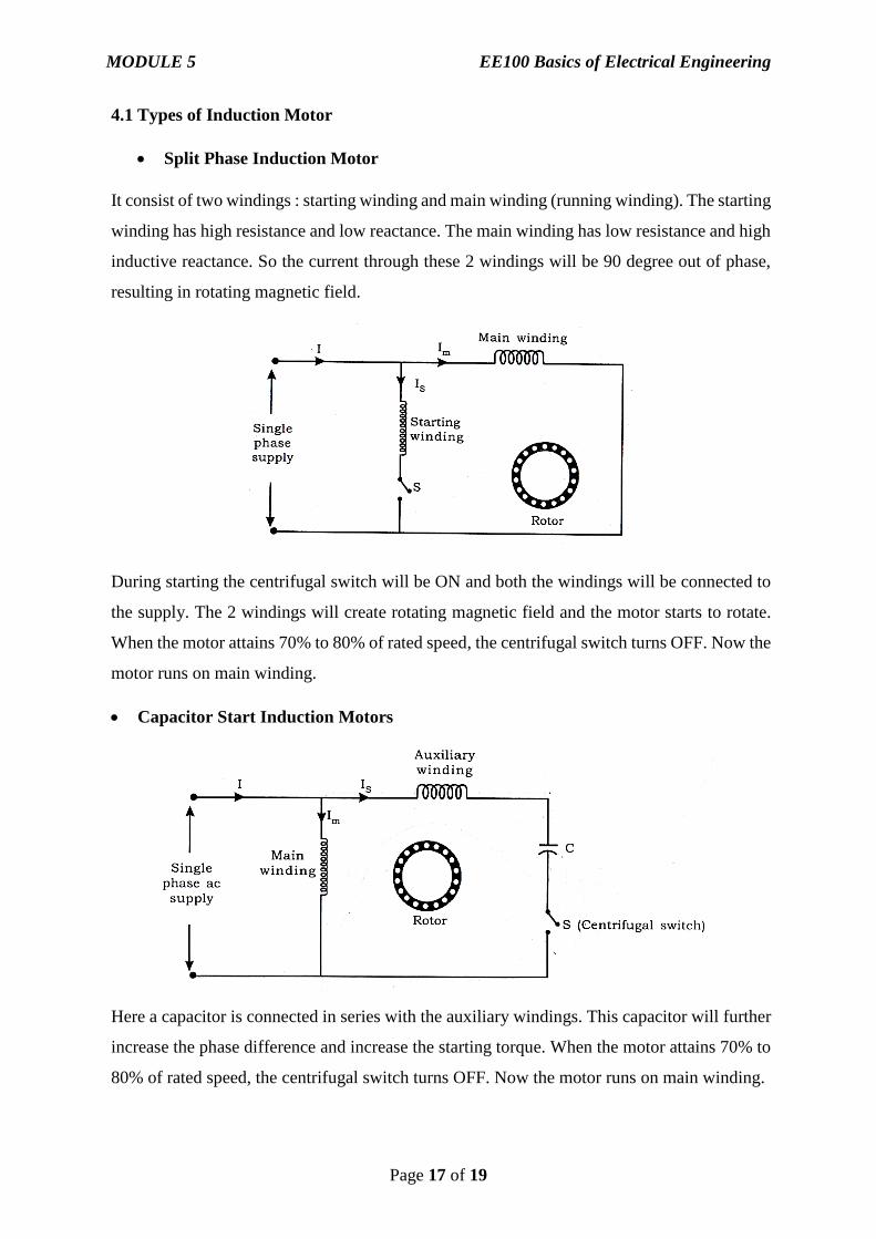
Split Phase Induction Motor
It consist of two windings : starting winding and main winding (running winding). The starting
winding has high resistance and low reactance. The main winding has low resistance and high
inductive reactance. So the current through these 2 windings will be 90 degree out of phase,
resulting in rotating magnetic field.
During starting the centrifugal switch will be ON and both the windings will be connected to
the supply. The 2 windings will create rotating magnetic field and the motor starts to rotate.
When the motor attains 70% to 80% of rated speed, the centrifugal switch turns OFF. Now the
motor runs on main winding.
Capacitor Start Induction Motors
Here a capacitor is connected in series with the auxiliary windings. This capacitor will further
increase the phase difference and increase the starting torque. When the motor attains 70% to
80% of rated speed, the centrifugal switch turns OFF. Now the motor runs on main winding.

MODULE 5 EE100 Basics of Electrical Engineering
Page 18 of 19
Capacitor Run Induction Motor.
Here a capacitor is connected in series with the auxiliary windings. This capacitor will further
increase the phase difference and increase the starting torque. There is no centrifugal switch
to disconnect auxiliary winding. These are also called permanent slip capacitor motor.
Capacitor Start Capacitor Run Induction Motor.
It consist of 2 capacitors connected in parallel. When the motor attains 70% to 80% of rated
speed, the centrifugal switch turns OFF and disconnects capacitor C2. The capacitor
C1improves the power factor.
Shaded Pole Induction Motors
These types of motors consist of projected poles as shown in figure below. Each pole is divided
into 2 parts. One part is shorted with copper ring called shading ring. This will create a flux on

MODULE 5 EE100 Basics of Electrical Engineering
Page 19 of 19
shaded portion which lags the main flux. This will create a rotating magnetic field and the
motor starts rotating.
4.2 Universal Motor
These are series motor which works on AC as well as DC. It is of two types
(i) Non Compensated Type
(ii) Compensated type.
These are used in mixies, grinder, drill, electric shaver, vacuum cleaer…