bass chap14.fm page 303 thursday, august 30, 2012...
TRANSCRIPT

303
14Flight SimulationA Case Study in Architecture for Integrability
The striking conclusion that one draws . . . is that the informationprocessing capacity of [flight simulation computation] has been
increasing approximately exponentially for nearly thirty years. Thereis at this time no clear indication that the trend is changing.
— Laurence Fogarty [Fogarty 67]
Modern flight simulators are among the most sophisticated software systems inexistence. They are highly distributed, have rigorous timing requirements, andmust be amenable to frequent updates to maintain high fidelity with the vehiclesand environment they are simulating. The creation and maintenance of theselarge systems present a substantial software development challenge: for perfor-mance, for integrability, and for modifiability. Scalability, a particular form ofmodifiability, is needed to grow these systems so that they can simulate more andmore of the real world and further improve the fidelity of the simulation.
This chapter will discuss some of the challenges of flight simulation andintroduce a new architectural style created to address them. The style is called astructural model, and it emphasizes the following:
■ Simplicity and similarity of the system’s substructures■ Decoupling of data and control passing strategies from computation■ Minimization of types of components■ A small number of systemwide coordination strategies■ Transparency of design
These principles result in an architectural style that, as we will see, features a highdegree of component integrability as well as the other quality attributes necessaryfor flight simulation.
Bass_chap14.fm Page 303 Thursday, August 30, 2012 2:48 PM
Excepted from Bass et al., Software Architecture in Practice, First Edition (ISBN-13: 9780201199307) Copyright © 1998 Pearson Education, Inc. Do not redistribute.

304 CHAPTER 14 Flight Simulation
14.1 Relationship to the Architecture Business Cycle
The segment of the archtecture business cycle (ABC) that connects desired quali-ties to architecture is the subject of this case study. Figure 14.1 shows the ABCfor structural-model-based flight simulators. Flight simulators are acquired bythe U.S. Air Force. The end users of the systems are pilots and crews for the par-ticular aircraft being simulated. The flight simulators are used for pilot training inthe operation of the aircraft, for crew training in the operation of the variousweapons systems on board, and for mission training for particular missions forthe aircraft. Some of these simulators are intended for stand-alone use, but moreand more they are intended to train multiple crews simultaneously for coopera-tive missions.
The flight simulators are constructed by a contractor selected as a result of acompetitive bidding process. Sometimes the contractor is a prime contractor, andportions of the flight simulator are constructed by specialized subcontractors.The flight simulator systems are large (some as large as 1.5 million lines ofcode), have long lifetimes (the aircraft being simulated often have lifetimes of 40years or longer), and have stringent real-time and fidelity requirements (the simu-lated aircraft must behave exactly as the real aircraft in various situations).
The beginning of the structural model design dates from 1987 when the U.S.Air Force began to investigate the application of object-oriented design techniques.
FIGURE 14.1 Initial stages of the ABC for the flight simulator.
Requirements (Qualities)Pilot and Crew TrainingModifiabilityIntegrabilityPerformance
Architect’s Influences
Customer and End UserUSAF Acquisition and USAF Pilots
Developing OrganizationVarious Contractors
Technical EnvironmentExisting Simulator Design
Architect’s ExperienceObject-Oriented Design and Hard Real-Time Design
Architect(s) ArchitectureStructuralModel
SystemFlightSimulator
Bass_chap14.fm Page 304 Thursday, August 30, 2012 2:48 PM
Excepted from Bass et al., Software Architecture in Practice, First Edition (ISBN-13: 9780201199307) Copyright © 1998 Pearson Education, Inc. Do not redistribute.

Requirements and Qualities 305
Electronic flight simulators have been in existence since the 1960s and so explo-ration into new design techniques was motivated by the existing designs and theproblems associated with them. The problems observed in existing flight simula-tors included construction problems (the integration phase of development wasincreasing exponentially with the size and complexity of the systems) and lifecycle problems (the cost of some modifications was exceeding the cost of theoriginal system). Structural models have been used in the development of the B-2Weapons System Trainer, the C-17 Aircrew Training System, and the SpecialOperations Forces family of trainers, among others.
14.2 Requirements and Qualities
Flight simulation has always been an application that needed to be distributed inorder to be computable at all. Although examples of single-processor flight simu-lators exist, they are typically of low fidelity, often games. True flight simulationhas extremely high-fidelity demands: The virtual environment that the simulatorcreates must be as lifelike as possible in order to train the aircrew as effectively aspossible.
Even in simulators created 30 years ago, distribution was used [Perry 66]:
Linear computing operations, such as summation, integration and signchanging, are performed by d.c. operational amplifiers, consisting ofhigh gain drift correct amplifiers with appropriate resistive or capacitivefeedback networks. There are 150 such operational amplifiers. . . . Thenon-linear part of the computing equipment consists of servo-multipliers,electronic time-division multipliers, and diode function generators. Inaddition, forty-eight high gain amplifiers are available for special com-puting circuits which may be built up for each simulation. . . . The indi-vidual computing amplifiers, potentiometers, multipliers, etc. are connectedtogether to form the overall computation network by means of a centralpatching panel, having over 2300 terminations.
Although the effects produced by such a simulator are primitive by today’s standards,many of the principles behind the system’s architecture have not changed. A sin-gle computer typically cannot provide the raw computation power to serve aflight simulator, or if it could, it would be horrendously expensive. This situationis not likely to change: As computer power increases, so do our demands and sodoes the complexity of the air vehicles being simulated. Thus, a number of com-puters were hooked together through a patch panel 30 years ago in order to createa flight simulator; today, they would typically be connected through a fiber-opticnetwork.
Flight simulation is characterized by the following six properties:
1. Real-time performance constraints. Flight simulators must execute atfixed frame rates that are high enough to ensure fidelity. For instance, the simu-
Bass_chap14.fm Page 305 Thursday, August 30, 2012 2:48 PM
Excepted from Bass et al., Software Architecture in Practice, First Edition (ISBN-13: 9780201199307) Copyright © 1998 Pearson Education, Inc. Do not redistribute.

306 CHAPTER 14 Flight Simulation
lated aircraft must respond to control inputs as quickly as the real aircraft would.Different senses require different frame rates. Within a frequency class—say, 30 Hzor 60 Hz—all simulations must be able to execute to completion within the basetime frame—one-thirtieth or one-sixtieth of a second.
All portions of a simulator run at an integral factor of the base rate. If thebase rate is 60 Hz, slower portions of the simulation may run at 30 Hz, 20 Hz, 15 Hz,or 12 Hz, and so on. They may not run at a nonintegral factor of the base rate,such as 25 Hz. One reason for this restriction is that the sensory inputs providedby a flight simulator for the crew being trained must be strictly coordinated. Itwould not do to have the pilot execute a turn but not begin to see the change visuallyor feel the change for even a small period of time (say, one-tenth of a second). Evenfor delays so small that they are not consciously detectable, a lack of coordinationmay be a problem. Such delays may result in a phenomenon known as simulatorsickness, a purely physiological reaction to imperfectly coordinated sensory inputs.
2. Continuous development and modification. Simulators exist for only onepurpose: to train users when the equivalent training on the actual vehicle would bemuch more expensive or dangerous. In order to provide a realistic training experi-ence, a flight simulator must be faithful to the actual air vehicle. However, airvehicles, whether civilian or military, are continually being modified and updated.The simulator software is, therefore, almost constantly modified and updated inorder to maintain verisimilitude. Furthermore, the training for which the simulatorsare used is continually extended to encompass new types of problems (malfunc-tions) that might occur to the aircraft.
3. Large size and high complexity. Flight simulators typically comprisefrom tens of thousands of lines of code for the simplest training simulation toover a million lines of code for complex, multiperson trainers. Furthermore, thecomplexity of flight simulators, mapped over a 30-year period, has shown expo-nential growth.
4. Developed in geographically distributed areas. Military flight simula-tors are typically developed in a distributed fashion for two reasons, one technicaland one political. The technical reason is that different portions of the develop-ment require different expertise, and so it is common practice for the general con-tractor to subcontract portions of the work to specialists. The political reason isthat high-technology jobs such as simulator development are political plums, andso many politicians fight to have a piece of the work in their jurisdiction. In eithercase, the integrability of the simulator—already problematic because of the sizeand complexity of the code—is made more difficult because the paths of commu-nication are long.
5. Very expensive debugging, testing, and modification. The complexityof flight simulation software, its real-time nature, and its tendency to be modifiedregularly all contribute to making the costs of testing, integrating, and modifyingthe software usually exceed the cost of development.
6. Unclear mapping between software structure and aircraft structure. Flightsimulators have traditionally been built with runtime efficiency as their primary
Bass_chap14.fm Page 306 Thursday, August 30, 2012 2:48 PM
Excepted from Bass et al., Software Architecture in Practice, First Edition (ISBN-13: 9780201199307) Copyright © 1998 Pearson Education, Inc. Do not redistribute.

Architectural Approach 307
quality goal. This is not surprising given their performance and fidelity requirementsand given that simulators were initially built on platforms with extremely limited,by today’s standards, memory and processing power.
Traditional design of flight simulator software was based on following con-trol loops through a cycle. These, in turn, were motivated by the tasks that causedthe loop to be activated. For example, suppose the pilot turns the aircraft left. Thepilot moves the rudder and aileron controls and this in turn moves the control sur-faces, which affects the aerodynamics and causes the aircraft to turn. In the simu-lator, there is a model that reflects the relationship between the controls, thesurfaces, the aerodynamics, and the orientation of the aircraft. In the originalflight simulator architecture, this model was contained in a module that might becalled Turn. There might be a similar module for level flight, another for takeoffand landing, and so forth. The basic decomposition strategy is based on examin-ing the tasks that the pilot and crew perform, modeling the components that actu-ally perform the task, and keeping all calculations as local as possible.
This strategy maximizes performance since any task is modeled in a singlemodule (or a small collection of modules) and thus the data movement necessaryto perform the calculations is minimized. The problem with this architecture isthat the same physical component is represented in multiple models and hence inmultiple modules. The extensive interactions among modules causes problemswith both modifiability and integration. If the module controlling turning is beingintegrated with the module controlling level flight and a problem is discovered inthe data being provided to the turning module, that same data are probably beingaccessed by the level flight module, and so there were many coupling effects tobe considered during integration and maintenance.
The growth in complexity (and its associated growth in cost) caused the U.S.Air Force organization that is responsible for the acquisition of flight simulatorsto begin to emphasize the software qualities of integrability and modifiability. Thisnew emphasis was in addition to the requirement for high-fidelity performance.
By integrability we mean the ability to reconcile different portions of thesystem during the integration phase of initial development. One of the conse-quences of the growth in complexity was the growth of the cost of integration.With a new system under development that was projected to be 50 percent largerthan the largest prior system (1.7 million lines of code), the integration phasealone would break the project’s budgets for time and cost.
14.3 Architectural Approach
To manage the numerous challenges that flight simulation posed for its softwaredesigners, a new culture of software design for flight simulation needed to be cre-ated. This design framework, called structural modeling, will be discussed for theremainder of this chapter. In brief, the design framework consists of an object-
Bass_chap14.fm Page 307 Thursday, August 30, 2012 2:48 PM
Excepted from Bass et al., Software Architecture in Practice, First Edition (ISBN-13: 9780201199307) Copyright © 1998 Pearson Education, Inc. Do not redistribute.

308 CHAPTER 14 Flight Simulation
oriented design to model the subsystems and components of the air vehicle andreal-time scheduling to control the execution order of the simulation’s subsystemsso that fidelity could be guaranteed. To expand slightly on what we said in theintroduction, the main tenets of structural modeling are as follows:
■ Simplicity and similarity of the architecture’s substructures so that the archi-tecture is easy to understand and, hence, modify.
■ Small number of systemwide coordination strategies, which simplifies the complex performance and scheduling issues in making a high-fidelity real-time system.
■ Indirect data relationships so that passing data between subsystems is done through intermediary components. In this way subsystems do not need to directly know of each others’ existence or the details of where data come from and go to. This greatly simplifies the integrability and modifiability of the architecture.
■ Separation of computation from decisions about how data and control are passed.
■ Transparency of design (making the objects in the flight simulator directly analogous to physical parts of the air vehicle being modeled). This makes the flight simulator easier to design, modify, and maintain over time.
The driving design goals and the techniques that allowed these goals to be metare summarized in Table 14.1.
14.4 Architectural Solution
Logically, flight training simulators have three interactive roles. The first role is thatof training the pilot and crew. They sit inside a motion platform, surrounded byinstruments intended to replicate exactly the aircraft being simulated, and look atvisuals that provide a representation of what would be seen outside of an actual air-craft. We are not going to describe the specifics of either the motion platform or thevisual display generator. These are driven by special-purpose processors and are
TABLE 14.1 How the Structural Modeling Paradigm Achieves Its Quality Goals
Goal How achieved
Performance Small number of systemwide coordination strategies and periodic scheduling strategy
Integrability Separation of computation from coordination and indirect data relationships
Modifiability Transparency of design, simplicity and similarity of substructures, and indirect data relationships
Bass_chap14.fm Page 308 Thursday, August 30, 2012 2:48 PM
Excepted from Bass et al., Software Architecture in Practice, First Edition (ISBN-13: 9780201199307) Copyright © 1998 Pearson Education, Inc. Do not redistribute.
Architectural Solution 309
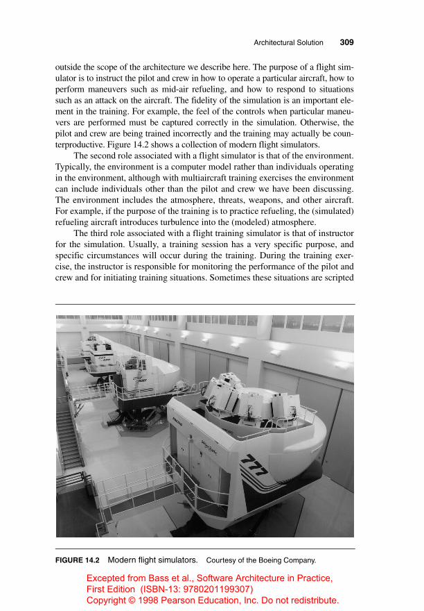
outside the scope of the architecture we describe here. The purpose of a flight sim-ulator is to instruct the pilot and crew in how to operate a particular aircraft, how toperform maneuvers such as mid-air refueling, and how to respond to situationssuch as an attack on the aircraft. The fidelity of the simulation is an important ele-ment in the training. For example, the feel of the controls when particular maneu-vers are performed must be captured correctly in the simulation. Otherwise, thepilot and crew are being trained incorrectly and the training may actually be coun-terproductive. Figure 14.2 shows a collection of modern flight simulators.
The second role associated with a flight simulator is that of the environment.Typically, the environment is a computer model rather than individuals operatingin the environment, although with multiaircraft training exercises the environmentcan include individuals other than the pilot and crew we have been discussing.The environment includes the atmosphere, threats, weapons, and other aircraft.For example, if the purpose of the training is to practice refueling, the (simulated)refueling aircraft introduces turbulence into the (modeled) atmosphere.
The third role associated with a flight training simulator is that of instructorfor the simulation. Usually, a training session has a very specific purpose, andspecific circumstances will occur during the training. During the training exer-cise, the instructor is responsible for monitoring the performance of the pilot andcrew and for initiating training situations. Sometimes these situations are scripted
FIGURE 14.2 Modern flight simulators. Courtesy of the Boeing Company.
Bass_chap14.fm Page 309 Thursday, August 30, 2012 2:48 PM
Excepted from Bass et al., Software Architecture in Practice, First Edition (ISBN-13: 9780201199307) Copyright © 1998 Pearson Education, Inc. Do not redistribute.

310 CHAPTER 14 Flight Simulation
in advance, and other times the instructor introduces them. Typical situationsinclude malfunctions of equipment (e.g., landing gear that does not deploy correctlyduring landing), attacks on the aircraft from foes, and weather conditions such asturbulence caused by thunderstorms. The instructor has a separate console that isused both to monitor the activities of the crew and to inject malfunctions into theaircraft and control the environment.
Figure 14.3 shows a reference model for a flight simulator. Typically, theinstructor is hosted on a different hardware platform from the air vehicle model.The environment model may be hosted either on a separate hardware platform oron the instructor station.
The division between the instructor station and the other two portions isclear from a real-time execution perspective. The instructor station is typicallyscheduled on an event basis—those events that emanate from the instructor’sinteractions—and the air vehicle model is scheduled by using a periodic schedul-ing procedure. The environment model can be scheduled using either regime,depending on the complexity and richness of the environment being modeled.This requirement to coordinate and match two different scheduling paradigmswill be revisited when we discuss the details of the structural model.
FIGURE 14.3 Reference model for a flight simulator.
Air Vehicle
Environment
InstructorStation
Cockpit Displays
Visual Cueing System
Motion Cueing System
Audio Cueing System Crew
Cockpit Controls
Bass_chap14.fm Page 310 Thursday, August 30, 2012 2:48 PM
Excepted from Bass et al., Software Architecture in Practice, First Edition (ISBN-13: 9780201199307) Copyright © 1998 Pearson Education, Inc. Do not redistribute.
Architectural Solution 311
The division between the instructor station and the other two portions is notas clean. For example, if an aircraft launches a weapon, it is logically a portion ofthe air vehicle until it leaves the air vehicle, at which point it becomes a portionof the environment. On firing, however, the aerodynamics of the weapon will beinfluenced initally by the proximity of the aircraft. Thus, any modeling of it mustremain, at least initially, tightly coupled to the air vehicle. If the weapon is alwaysconsidered a portion of the environment, the modeling of the weapon involvestight coordination between the air vehicle and the environment. If it is modeled asa portion of the air vehicle and then handed off to the environment when fired,control of the weapon needs to be handed from one scheduling regime to another.Even if the environment is scheduled using a periodic scheduling regime, it islikely to operate on a different granularity from that of the environment model.
The simulated behavior of the air vehicle is not calculated from first physi-cal principles. Such simulations are used during the engineering process and arecalled engineering simulations, but they cannot yet be done within the constraintsthat real-time processing impose. Consequently, the simulations are performedusing models supplemented with empirical data. For example, the thrust of anengine might be measured using the whole engine, but the impact of an individ-ual rotor is not measured. Thus, if a rotor is replaced, keeping the simulation cor-rect can be difficult.
For the rest of this section we focus primarily on the architecture of the airvehicle model. But before we can do that, we need a basic understanding of theways in which time is treated in this domain.
TREATMENT OF TIME IN A FLIGHT SIMULATOR
Time and how it is managed is a critical consideration in the development of aflight simulator. Time is important because a flight simulator is supposed to re-flect the real world, and it does this by creating time-based behaviors as theywould occur in the real world. Thus, when the pilot in a simulator pushes on theflight control, the simulator must provide the same response in the same time asthe actual aircraft would. “In the same time” means both within an upper bound ofduration after the event and also within a lower bound of duration. Reacting tooquickly is as bad for the quality of the simulation as reacting too slowly.
There are two fundamentally different ways of managing time in a flightsimulator: periodic and event-based.
Periodic Time Management. A periodic time-management scheme has a fixed(simulated) time quantum that is the basis of scheduling the system processes. Ittypically uses a nonpreemptive cyclic scheduling discipline. The scheduler pro-ceeds by iterating through the following loop:
■ Set initial simulated time.■ Iterate next two steps until the session is complete.
Bass_chap14.fm Page 311 Thursday, August 30, 2012 2:48 PM
Excepted from Bass et al., Software Architecture in Practice, First Edition (ISBN-13: 9780201199307) Copyright © 1998 Pearson Education, Inc. Do not redistribute.

312 CHAPTER 14 Flight Simulation
■ Invoke each of the processes for a fixed (real) quantum. Each of the invoked processes calculates its internal state based on the current simulated time and reports its internal state based on the next period of simulated time. Each invoked process guarantees to complete its computation within its real-time quantum.
■ Increment simulated time by quantum.
A simulation based on the periodic management of time will be able to keep thesimulated time and the real time in synchronization as long as each individualprocess is able to advance its state to the next period within the time quantum thatit has been allocated.
Typically, this is managed by adjusting the responsibilities of the individualprocesses so that they are small enough to be computed in the allocated quantumand then using multiple processors, if necessary, to ensure enough computationpower to enable all of the processes to receive their quantum of computation.
A periodic simulator scheduling scheme is used when many activities arehappening in parallel in simulated time. Thus, for example, when the simulation isbased on the simultaneous solution of a collection of differential equations, a solu-tion technique based on finite differences leads to a periodic scheduling strategy.
Event-Based Time Management. An event-based time-management schemeis similar to interrupt-based scheduling used in many operating systems. Theschedule proceeds by iterating through the following loop:
■ Add initial simulated event to the event queue.■ While there are events remaining in the event queue:
– Choose event in event queue with smallest (i.e., soonest) simulated time.
– Set current simulated time to time of chosen event.
– Invoke process that processes the chosen event. This process may add events to the event queue.
In this case, simulated time advances by the invoked processes placing events onthe event queue and the scheduler choosing the next event to process. There is noguarantee about the relationship of simulated time to real time and no guaranteeabout the amount of resources consumed by each process that is invoked.
Event-based simulations assume that the management of the event queue isnot a major drain on resources. That is, the number of events occurring at a singleinstant of simulated time is small compared to the effort of managing those events.
Mixed-Time Systems. Flight simulators must marry periodic time simulation(such as in the air vehicle model) with event-based simulation (such as in theenvironment model, in some cases) and with other event based activities that arenot predictable (such as an interaction with the instructor station or the pilot set-ting a switch). Many scheduling policies are possible in such a marriage.
Bass_chap14.fm Page 312 Thursday, August 30, 2012 2:48 PM
Excepted from Bass et al., Software Architecture in Practice, First Edition (ISBN-13: 9780201199307) Copyright © 1998 Pearson Education, Inc. Do not redistribute.

Architectural Solution 313
A simple policy states that periodic processing occurs immediately after thesynchronization interval and is completed before any aperiodic processing. Ape-riodic processing then proceeds within a bounded interval, during which as manymessages as possible will be retrieved and processed. Those not processed duringa given interval must be deferred to subsequent intervals, with the requirementthat all messages be processed in the order received from a single source.
Given this understanding of the issues involved in managing time in a flightsimulator, we can now present the architectural style that manages this complexity.
THE STRUCTURAL MODEL ARCHITECTURAL STYLE
The structural model is an architectural style as we defined it in section 2.2. Thatis, it consists of a collection of component configurations and a description ofhow these configurations coordinate at runtime. In this section, we present thestructural model and discuss the considerations that led to its design. The struc-tural model we present here is focused on the air vehicle model. One aspect tokeep in mind is that the air vehicle model may itself be spread over several pro-cessors. Thus, the elements of the air vehicle structural model must coordinateinternally as well as coordinate with the environment model and the instructorportions of the simulation.
A flight simulator can execute in several states including the following:
■ Operate corresponds to the normal functioning of the simulator as a training tool.
■ Configure is used when modifications must be made to a current training session. For example, suppose the crew has been training in an environment in which they have been flying in a single-aircraft exercise, and then the instructor wishes to train them for a mid-air refueling exercise. The simula-tor is then placed into a configure state.
■ Halt stops the current simulation.■ Replay uses a journal to move through the simulation without crew interac-
tion. Replay is used, among other functions, to demonstrate to the crew what they have just done because the crew may get caught up in the operating of the aircraft and not reflect on their actions.
The structural modeling architectural style is divided, at the coarsest level, intotwo parts: executive and application.
The executive part handles coordination issues: real-time scheduling of sub-systems, synchronization between processors, event management from theinstructor–operator station, data sharing, and data integrity.
The application part handles the actual computation of the flight simulation:modeling the air vehicle. The application’s functions are implemented by subsys-tems and their constituent components. First we will discuss the executive stylein detail and then return to a discussion of the application style.
Bass_chap14.fm Page 313 Thursday, August 30, 2012 2:48 PM
Excepted from Bass et al., Software Architecture in Practice, First Edition (ISBN-13: 9780201199307) Copyright © 1998 Pearson Education, Inc. Do not redistribute.

314 CHAPTER 14 Flight Simulation
COMPONENT CONFIGURATIONS FOR AIR VEHICLE MODEL EXECUTIVE
Figure 14.4 shows the air vehicle structural model with the executive componentconfigurations given in detail. These are the timeline synchronizer, the periodic se-quencer, the event handler, and the surrogates for other portions of the simulator.
Timeline Synchronizer. The timeline synchronizer is the base schedulingmechanism for the air vehicle model. It also maintains the simulation’s internalnotion of time. The other three elements of the executive—the periodic sequencer,the event handler, and the surrogates—all must be allocated processor resources.The timeline synchronizer also maintains the current state of the simulation.
The timeline synchronizer passes both data and control to the other threeelements and receives data and control from them. It is also responsible for coordi-nating time with other portions of the simulator. This can include other processorsresponsible for a portion of the air vehicle model, which also have their own time-line synchronizers. Finally, the timeline synchronizer implements a scheduling
FIGURE 14.4 The structural model style of an air vehicle system processor with focus on the executive.
Surrogate
TimelineSynchronizer
send
receive
import
export
PeriodicSequencer
update
import
EventHandlerget_outbound_msg
constituent_event
configure
send
Air VehicleSubsystem
import
update
configure
process_event
process_event
Networkto otherprocessors
Bass_chap14.fm Page 314 Thursday, August 30, 2012 2:48 PM
Excepted from Bass et al., Software Architecture in Practice, First Edition (ISBN-13: 9780201199307) Copyright © 1998 Pearson Education, Inc. Do not redistribute.

Architectural Solution 315
policy for coordinating both periodic and aperiodic processing. For the sake ofcontinuity, precedence is given to the periodic processing.
Periodic Sequencer. The periodic sequencer is used to conduct all periodicprocessing performed by the simulation’s subsystems. This involves invoking thesubsystems to perform periodic operations according to fixed schedules.
The periodic sequencer provides two operations to the timeline synchronizer.The import operation is used to request the periodic sequencer to invoke sub-systems to perform their import operation. The update operation requeststhat the periodic sequencer invoke the update operations of the subsystems.
To conduct its processing, the periodic sequencer requires two capabilities.The first is to organize knowledge of a schedule. By schedule we mean the patternsof constituent invocations that represent the orders and rates at which changes arepropagated through the simulation algorithms realized by the constituents. Theenactment of these patterns essentially represents the passage of time within theair vehicle simulation in its various operating states. The second capability is toactually invoke the subsystems through their periodic operations by means ofsome dispatching mechanism.
Event Handler. The event-handler element is used to orchestrate all aperiodicprocessing performed by subsystems. This involves invoking the subsystems byaperiodic operations appropriate to the current system operating state.
The event handler provides four kinds of operations to the timeline syn-chronizer: configure (used to start a new training mission, for example),constituent_event (used when an event is targeted for a particularinstance of a component), get_outbound_msg (used by the timeline synchro-nizer to conduct aperiodic processing while in system operating states, such asoperate, that are predominantly periodic), and send (used by subsystem con-trollers to send events to other subsystem controllers and messages to other systems).
To perform its processing, the event handler requires two capabilities. Thefirst is a capability to determine which subsystem controller receives an event,using knowledge of a mapping between event identifiers and instances. The sec-ond is a capability to invoke the subsystems and to extract required parametersfrom events before invocation.
Surrogate. Surrogates are responsible for system-to-system communicationbetween the air vehicle model and the environment model or the instructor sta-tion. Surrogates are aware of the physical details of the system with which theycommunicate and are responsible for issues such as representation, communica-tion protocol, and so forth.
For example, the instructor station monitors state data from the air vehiclemodel and displays the data to the instructor. The surrogate gathers the correctdata when it gets control of the processor and sends that data to the instructor sta-tion. In the other direction, the instructor may wish to set a particular state for thecrew. This is an event that is received by the surrogate and passed to the eventprocessor for dispatching to the appropriate subsystems.
Bass_chap14.fm Page 315 Thursday, August 30, 2012 2:48 PM
Excepted from Bass et al., Software Architecture in Practice, First Edition (ISBN-13: 9780201199307) Copyright © 1998 Pearson Education, Inc. Do not redistribute.

316 CHAPTER 14 Flight Simulation
This use of surrogates means that both the periodic scheduler and the eventhandler can be kept ignorant of the details of the instructor station or the platformon which the environment model is operating. All of the system-specific knowl-edge is embedded in the surrogate. Any change to these platforms will not propa-gate further than the surrogate in the air vehicle model system.
COMPONENT CONFIGURATIONS FOR AIR VEHICLE MODEL APPLICATION
Figure 14.5 shows the component configurations that exist in the application sub-part of the air vehicle srtuctural model. There are only two of them: the subsystemcontroller and its components. The term component, as used in the structuralmodel, refers to a specific component type. This terminological ambiguity isrestricted to this section, and we hope it will not cause confusion. Subsystemcontrollers pass data to and from other subsystem controller instances but only totheir child components. Components will pass data only to and from their parentsand not to any other component. They will also receive control only from theirparents and return it only to their parents. These restrictions on data and controlpassing preclude a component from passing data or control even to a sibling com-ponent. The rationale for these restrictions is to assist in integration and modifi-ability by eliminating any coupling of a component instance with anything otherthan its parent. Any effect of modification or integration is mediated by the par-ent subsystem controller.
Subsystem Controller. Subsystem controllers are used to interconnect a setof functionally related components to do the following:
■ Achieve the simulation of a subsystem as a whole■ Mediate control and aperiodic communication between the system and
subsystems
They are also responsible for determining how to use the capabilities of theircomponents to satisfy trainer-specific functionality such as malfunctions and thesetting of parameters.
A subsystem controller must provide the capability to make logical connectionsbetween its components and those of other subsystems. Inbound connectionssupply inputs produced outside of the subsystem that the subsystem’s compo-nents need for their simulation algorithms. Outbound connections satisfy similarneeds of other subsystems and of surrogates. These connections appear as sets ofnames by which a subsystem controller internally refers to data considered to beoutside of itself. When such a name is read or written, the appropriate connec-tions are assumed to be made. How the connections are actually made is deter-mined later in the detailed design.
Subsystem controllers must both order the update operations of their com-ponents and interconnect their inputs and outputs. This achieves the desired prop-
Bass_chap14.fm Page 316 Thursday, August 30, 2012 2:48 PM
Excepted from Bass et al., Software Architecture in Practice, First Edition (ISBN-13: 9780201199307) Copyright © 1998 Pearson Education, Inc. Do not redistribute.

Architectural Solution 317
agation of changes through the components and satisfies the subsystem’soutbound connections. The subsystem controller synthesizes, from its components,a simulation algorithm for the subsystem as a whole. In addition to updatingcomponents, the controller may be responsible for making intermediate computa-tions as well as data transformations and conversions.
As we mentioned, a flight simulator can be in one of several states. This istranslated through the executive to particular executive states. The executive theninforms the subsystem controller of its current state. The two states that are rele-vant here are operate and stabilize. The operate state instructs the subsystem con-troller to perform its normal computations relevant to advancing the state of thesimulation. The stabilize state informs the subsystem controller to terminate itscurrent computation in a controlled fashion (to prevent the motion platform fromharming the crew through uncontrolled motion), as follows:
■ Retrieve and locally store the values of inbound connections under the direct control of an executive. Such a capability is provided to address issues of data consistency and time coherence.
■ Stabilize the simulation algorithms of its components under the control of executive instances and report whether it considers the subsystem as a whole to be currently stable.
Subsystem controllers must be able to do the following:
■ Initialize themselves and each of their components to a set of initial condi-tions in response to an event
■ Route requests for malfunctions and the setting of simulation parameters to their components based on knowledge of component capabilities
FIGURE 14.5 The application component configurations.
SubsystemController
process_event
update
Component
configure
process_event
update
import
configure
Bass_chap14.fm Page 317 Thursday, August 30, 2012 2:48 PM
Excepted from Bass et al., Software Architecture in Practice, First Edition (ISBN-13: 9780201199307) Copyright © 1998 Pearson Education, Inc. Do not redistribute.

318 CHAPTER 14 Flight Simulation
Finally, subsystem controllers may support the reconfiguration of missionparameters such as armaments, cargo loads, the starting location of a trainingmission, and so forth. Subsystem controllers realize these capabilities throughperiodic and aperiodic operations made available to the periodic sequencer andevent handler, respectively.
There are two periodic operations provided by system controllers: updateand import.
The update operation causes the subsystem controller to perform periodicprocessing appropriate to the current system operating state, which is provided asan input parameter. In the operate state, the update operation causes the sub-system controller to retrieve inputs needed by its components by means ofinbound connections, execute operations of its components in some logical orderso that changes can be propagated through them, and retrieve their outputs for usein satisfying another’s inputs or the subsystem’s outbound connections. Morethan just a sequencer, this algorithm provides logical “glue” that cements thecomponents into some coherent, aggregate simulation. This glue may includecomputations as well as data transformations and conversions.
In the stabilize state, the update operation is used to request the subsystemcontroller to perform one iteration of its stabilization algorithm and determinewhether locally defined stability criteria are satisfied. The update operation pro-vides one output parameter, indicating whether the subsystem controller consid-ers the subsystem to be currently stable. This makes the assumption that such adetermination can be made locally, which may not be valid in all circumstances.Subsystem controllers may provide the capability to do the following tasks.
The import operation is used to request the subsystem controller to completecertain of its inbound connections by reading their values and locally store theirvalues for use in a subsequent update operation. There are two aperiodic opera-tions provided by subsystem controllers: process_event and configure.
The process_event operation is used in operating states that are pre-dominantly periodic, such as operate, to ask the subsystem controller to respondto an event. A characteristic of this operation is that effects of servicing the eventare reflected only in the subsystem’s periodic outputs, which are not made availableuntil the next update operation. The event is provided by an input parameter to theoperation. Several events from the instructor–operator station fall into this category,such as process_malfunction, set_parameter, and hold_parameter.
The configure operation is used in system operating states, like initialize, inwhich the processing is predominantly aperiodic. The operation is used to establisha named set of conditions such as some training device configuration or trainingmission. The information that the subsystem controller needs to establish thecondition may be provided as an input parameter on the operation, as a locationin a memory on secondary storage, or in a database where the information has beenstored for retrieval. To complete the operation, the subsystem controller invokesoperations of its components that cause the components to establish the conditions.
Component. Air vehicle model components can be simulations of real aircraftcomponents, such as a hydraulic pump, an electrical relay, an engine rotor, a fuel
Bass_chap14.fm Page 318 Thursday, August 30, 2012 2:48 PM
Excepted from Bass et al., Software Architecture in Practice, First Edition (ISBN-13: 9780201199307) Copyright © 1998 Pearson Education, Inc. Do not redistribute.

Architectural Solution 319
tank, and the like. They can support simulator-specific models such as forces andmoments, weights and balances, and the equations of motion. They can be usedto localize the details of cockpit equipment, such as gauges, switches, and dis-plays. But no matter what specific functionality they are used to simulate, com-ponents are all considered to be architecturally equivalent.
In general, components are used to support the simulation of an individualpart, or object, within some functional assembly. Each component provides a sim-ulation algorithm that determines the state of the component based on the following:
■ Its former state■ Inputs that represent its connections with logically adjacent components■ Some elapsed time interval
A component makes this determination as often as it is requested to do so by itssubsystem controller, which provides the required inputs and receives the compo-nent’s outputs. This capability is called updating.
A component can support the capability to produce abnormal outputs,reflecting a malfunction condition. In addition to potentially modeling changes innormal operating conditions that can result in malfunctions over time, such aswear and tear, components can be told to start and stop malfunctioning by theirsubsystem controller.
A component can also support the capability to set a simulation parameter toa particular value. Simulation parameters are external names for performanceparameters and decision criteria used in its simulation algorithm. Each compo-nent supports the capability to initialize itself to some known condition. Like theother capabilities of components, parameter setting and initialization must berequested by the subsystem controller.
The capabilities of updating and those of malfunctioning, parameter setting,and initializing differ in the incidence of their use by the subsystem controller.The component is requested to update on a periodic basis, effecting the passageof time within the simulation. Requests for the other capabilities are made onlysporadically.
Components support these capabilities through a set of periodic and aperi-odic operations made available to the subsystem controller. The update opera-tion is the single periodic operation and is used to control the periodic executionof the simulation algorithm. The component receives external inputs and returnsits outputs through parameters on the operation. Two aperiodic operations areprovided by the components process_event and configure.
All logical interactions among components are mediated by the subsystemcontroller, which is encoded with knowledge of how to use the component oper-ations to achieve the simulation requirements allocated to the subsystem as awhole. This includes the following:
■ Periodically propagating state changes through the components using their update operations
Bass_chap14.fm Page 319 Thursday, August 30, 2012 2:48 PM
Excepted from Bass et al., Software Architecture in Practice, First Edition (ISBN-13: 9780201199307) Copyright © 1998 Pearson Education, Inc. Do not redistribute.
320 CHAPTER 14 Flight Simulation
■ Making logical connections among components using the input and output parameters on these operations
■ Making logical connections among components and the rest of the simula-tion using the subsystem’s inbound and outbound connections
Component malfunctions are assumed to be associated with abnormal oper-ating conditions of the real-world components being modeled. Therefore, thepresence and identities of component malfunctions are decided by the componentdesigner and are made known to the subsystem controller designer for use in real-izing subsystem malfunction requests. Subsystem malfunctions need not corre-spond directly to those supported by the components, and certain subsystemmalfunctions can be realized as some aggregation of more primitive failures sup-ported by components. It is the subsystem controller’s responsibility to realizesome mapping between the two.
Likewise, the presence and identities of simulation parameters are decidedby the component designer based on the characteristics of the component’s simu-lation algorithm. They are made known to the subsystem controller designer foruse in realizing subsystem requests or for other purposes for which they areintended or are suitable to support.
Skeletal System and Pattern-Based Simplicity. What we have now describedis a skeletal system, as defined in Section 13.2. We have a framework for a flightsimulator, but none of the details—the functionality—have been filled in. In fact,this framework has also been used for helicopter simulation and even nuclearreactor simulation. The process of realizing a working simulation consists offleshing out this skeleton with subsystems and components, as dictated by thefunctional partitioning process, which will be discussed next.
An entire flight simulator, which can easily exceed 1 million lines of code,can be described completely by six component types: components, subsystemcontrollers, timeline synchronizer, periodic sequencer, event handler, and surrogate.This is an example of pattern-based simplicity, as we discussed in Section 13.3,and it renders the architecture easier to build, understand, integrate, grow, andotherwise modify.
Equally important, with a standard set of fundamental patterns, one can cre-ate specification forms, code templates, and exemplars that describe those pat-terns. This allows for consistent analysis. When these patterns are mandated, anarchitect can insist that a designer use only the provided building blocks. Whilethis may sound draconian, a small number of fundamental building blocks can, infact, free a designer to concentrate on the functionality, the reason that the systemis being built in the first place.
Both of these architectural approaches—skeletal system framework and pat-tern-based simplicity—have contributed significantly to the success of the struc-tural modeling approach.
Bass_chap14.fm Page 320 Thursday, August 30, 2012 2:48 PM
Excepted from Bass et al., Software Architecture in Practice, First Edition (ISBN-13: 9780201199307) Copyright © 1998 Pearson Education, Inc. Do not redistribute.

Architectural Solution 321
REFERENCE ARCHITECTURE
Now that we have described the architectural style with which the air vehiclemodel is built, we still need to discuss how operational functionality is allocatedto instances of that style. That is, we need to define the reference architecture. Wedo this by defining instances of the subsystem controllers.
The reference architecture is the place where the specifics of the aircraft tobe simulated are detailed. The actual partitioning depends on the systems on theaircraft, the complexity of the aircraft, and the types of training for which thesimulator is designed. In this section, we sketch a reference architecture.
We begin with a desire to partition the functionality to components based onthe underlying physical aircraft. To accomplish this we use an object-orienteddecomposition approach. This has a number of virtues, as follows:
■ It maintains a close correspondence between the aircraft partitions and the simulator, and this provides us with a set of conceptual models that map closely to the real world. Our understanding of how the parts interact in the aircraft helps us understand how the parts interact in the simulator. It also makes it easier for users and reviewers to understand the simulator. They are familiar with the aircraft (problem domain), and they can easily transfer this understanding to the simulator (solution domain).
■ Experience with past flight simulators has taught us that a change in the air-craft is easily identifiable with aircraft partitions. Thus the locus of the change in the simulator corresponds to analogous aircraft partitions. This tends to keep the simulator changes localized and well defined. It also makes it easier to understand how changes in the aircraft affect the simulator, therefore making it easier to assess the cost and time required for changes to be implemented.
■ The number and size of the simulator interfaces are reduced. This derives from a strong functional cohesion within partitions, placing the largest inter-faces within partitions instead of across them.
■ Localization of malfunctions is also achieved. Malfunctions are associated with specific pieces of aircraft equipment. It is easier to analyze the effects of malfunctions when dealing with this physical mapping, and the resulting implementations exhibit good locality. The effects of malfunctions are readily propagated in a natural fashion by the data that the malfunctioning partition produces. Higher-order effects are handled the same as first-order effects.
In breaking down the air vehicle modeling problem into more manageableunits, the airframe becomes the focus of attention. Groups exist for the airframe, theforces on the airframe, those things outside the airframe, and those things inside theairframe but ancillary to its operation. This results in the following specific groups:
■ Kinetics group. Elements that deal with forces exerted on the airframe■ Aircraft systems group. Those parts concerned with common systems that
provide the aircraft with various kinds of power or distribute energy within the airframe
Bass_chap14.fm Page 321 Thursday, August 30, 2012 2:48 PM
Excepted from Bass et al., Software Architecture in Practice, First Edition (ISBN-13: 9780201199307) Copyright © 1998 Pearson Education, Inc. Do not redistribute.

322 CHAPTER 14 Flight Simulation
■ Avionics group. Those things that provide some sort of ancillary support to the aircraft but are not directly involved in the kinetics of the air vehicle model, the vehicle’s control, or operation of the basic flight systems
■ Environment group. Those things associated with the environment in which the air vehicle model operates
GROUP DECOMPOSITION
In this section we motivate the coarsest decomposition of the air vehicle model—the group decomposition. Groups decompose into systems which, in turn, decom-pose into subsystems. These subsystems provide the instances of the subsystemcontrollers. Groups and systems are not directly reflected in the architecture andexist to rationalize the functionality assigned to the various instances of subsystemcontrollers. For now, we begin with groups.
N-Square Charts. One method of presenting information about the interfacesin a system is provided by n-square charts. We will make use of this presentationmethod to illustrate how the partitions we selected relate to each other. Becausesome of the factors we consider in making partitioning decisions are based on theinterfaces between the partitions, n-square charts are useful in evaluating thedecisions. They are a good method for illustrating the overall view of interfacesand can be used to illustrate the abstractions utilized in various parts of the design.
An example n-square chart is shown in Figure 14.6. The boxes on the maindiagonal represent the system partitions. Their inputs are found in the column inwhich the partition lies. The outputs from the partition are shown in the row inwhich the partition lies. Therefore the full set of inputs to a partition is the unionof all the cell contents of the partition’s column. Conversely, the full set of outputsis the union of all the cell contents in the row in which the partition resides. Theflow of data from one partition to another is to the right, then down, to the left,and then up.
FIGURE 14.6 The n-square chart.
Partition 1
Partition 2
Partition 3
Outputs
Inputs
Outputs
Inputs
Bass_chap14.fm Page 322 Thursday, August 30, 2012 2:48 PM
Excepted from Bass et al., Software Architecture in Practice, First Edition (ISBN-13: 9780201199307) Copyright © 1998 Pearson Education, Inc. Do not redistribute.

Architectural Solution 323
Figure 14.7 shows an n-square chart depicting the interfaces between thegroups we identified above. Interfaces external to the air vehicle model have beenomitted to simplify the chart. The external interfaces terminate in interface sub-systems.The data elements shown on this chart are aggregate collections of datato simplify the presentation. The interfaces are not named here, nor are theytyped. As we investigate partitions, looking at more limited sets of elements, thedetail of the information presented increases accordingly. Systems engineers canuse this approach to the point where all of the primitive data objects in the inter-faces are shown. During detailed design, the interface types and names will bedetermined and the structure finalized.
Not all of the air vehicle models will have a correspondence to aircraft struc-ture. The aerodynamics models are expressions of the underlying physics of thevehicle’s interaction with the environment. There are few direct analogs to air-craft parts. Partitioning this area will mean relying on the mathematical modelsand physical entities used to describe the vehicle’s dynamics. Partitioning cor-rectly based on mathematical models that affect the total aircraft is more difficultto do than partitioning based on the physical structure of the aircraft.
DECOMPOSING GROUPS INTO SYSTEMS
The next step is to refine the groups into systems. A system and a group can beunits of integration: The functionality contained within the system is a relativelyself-contained solution to a set of simulation problems. These units are a conve-nient focus for testing and validation. Partitions of groups exist as collections ofcode modules implemented by one engineer or a small group of engineers. Wecan identify systems within the groups we have defined above. We will lookbriefly at the kinetics group systems.
FIGURE 14.7 Air vehicle model domain n-square chart for groups.
Kinetics Group
Power
Inertial State
Atmosphere,Terrain, andWeather Data
Loads
AircraftSystems Group
Loads
Vehicle StateVector
Power
Avionics Group
EnvironmentEmitter Data
Vehicle Position
OwnshipEmissions
EnvironmentGroup
Bass_chap14.fm Page 323 Thursday, August 30, 2012 2:48 PM
Excepted from Bass et al., Software Architecture in Practice, First Edition (ISBN-13: 9780201199307) Copyright © 1998 Pearson Education, Inc. Do not redistribute.

324 CHAPTER 14 Flight Simulation
Systems in the Kinetics Group. These systems consist of elements concernedwith the kinetics of the vehicle. Included in this group are elements directlyinvolved in controlling the motion of the vehicle and modeling the interaction ofthe vehicle and its control surfaces with the environment. The systems identifiedin this group are as follows:
■ Airframe■ Propulsion■ Landing gear■ Flight controls
All of the subsystems in the propulsion system shown in Figure 14.8 deal withthe model of the aircraft’s engines. Multiple engines are handled by creating mul-tiple sets of state variables and duplicate instances of objects, where appropriate.This system’s principal purpose is to calculate engine thrust, moments caused byrotation of engine parts, and the forces and moments caused by mass distributionof fuel.
The aircraft’s fuel system is grouped here because the primary interface forthe fuel system is to the engines. The fuel system calculates the forces acting onthe airframe from movement of the fuel within the tanks as well as the gravita-tional effect of the fuel mass. At this point the reference architecture for the pro-pulsion subsystem is complete. We have identified the division of functionality,its allocation to subsystems and subsystem controllers, and the connectionsamong subsystems.
To complete the architecture, we would need to do the following:
■ Identify the component instances for the propulsion subsystem.■ Similarly decompose the other groups, their systems, and their subsystems.
This, however, concludes the presentation of the architecture in this case study.
FIGURE 14.8 Propulsion subsystems.
PropulsionPanel
FuelEngine OilEngine Starter
Engine Core Engine InletEngine Ignition
Bass_chap14.fm Page 324 Thursday, August 30, 2012 2:48 PM
Excepted from Bass et al., Software Architecture in Practice, First Edition (ISBN-13: 9780201199307) Copyright © 1998 Pearson Education, Inc. Do not redistribute.

Achievement of Goals 325
14.5 Achievement of Goals
Structural modeling has been an unqualified success. Chastek and Brownsworddescribe some of the results achieved through the use of this architectural style[Chastek 96, 28]:
In a previous data-driven simulator of comparable size (the B-52), 2000–3000 test descriptions (test problems) were identified during factoryacceptance testing. With their structural modeling project, 600–700 testdescriptions were reported. They found the problems easier to correct;many resulted from misunderstandings with the documentation. . . . Stafftypically could isolate a reported problem off-line rather than going to asite. . . . Since the use of structural modeling, defect rates for one projectare half that found on previous data-driven simulators.
At the start of this chapter we identified three quality goals of structuralmodeling: performance, integrability, and modifiability for operational requirements.In this section, we recap how the structural model achieves these quality goals.
PERFORMANCE
A key quality goal of the structural model is real-time performance. This goal isachieved primarily through the operation of the executive and the use of a peri-odic scheduling strategy. Each subsystem that is invoked by the executive has atime budget, and the hardware for the simulator is sized so that it can accommo-date the sum of the time budgets of the subsystems. Sometimes this involves asingle processor, other times, multiple processors. Given this scheduling strategy,the achievement of real-time performance comes from requiring the sum of thetimes allocated to the subsystems involved in the control loops to be within oneperiod of the simulator. Thus, real-time performance is guaranteed by a combina-tion of architectural style (the executive component configurations) and the func-tional decomposition (how the instances are invoked).
INTEGRABILITY
In Chapters 4 and 5, we discussed how qualities are embedded into an architecture.In this chapter, we see an example in which the architectural style is designed tominimize integration problems. This approach is to minimize the connectionsbetween the various component configurations used in the structural model.
In the structural model, both the data connections and the control connec-tions between two subsystems are deliberately minimized. First, within a subsys-tem, the components can neither pass control nor data directly to any siblingcomponent. Any data or control transfer occurs only through the mediation of the
Bass_chap14.fm Page 325 Thursday, August 30, 2012 2:48 PM
Excepted from Bass et al., Software Architecture in Practice, First Edition (ISBN-13: 9780201199307) Copyright © 1998 Pearson Education, Inc. Do not redistribute.

326 CHAPTER 14 Flight Simulation
subsystem controller. Thus, integrating another component into a subsysteminvolves ensuring that the data in the subsystem controller are internally consis-tent and that the data transferred between the subsystem controller and the com-ponent are correct. This is a much simpler process than if the new componentcommunicated with other components because all of them would be involved inthe integration. That is, the integration problem has been reduced to a problemthat is linear, rather than exponential, in the number of components.
When integrating two subsystems, none of their components interact directlyand so the problem is again reduced to ensuring that the two subsystems pass dataconsistently. It is possible that the addition of a new subsystem will affect severalother subsystems, but because the number of subsystems is substantially less thanthe number of components, this problem is limited in complexity.
In the structural model, therefore, integrability is simplified by deliberatelyrestricting the number of possible connections. The cost for this restriction is thatthe subsystem controllers often act purely as data conduits for the various compo-nents, and this adds complexity. The benefits of this approach, however, far out-weigh the cost in practice. Every project that has used structural modeling hasreported easy, smooth integration.
MODIFIABILITY
Modifiability is simplified when there are few base component configurations forthe designer and maintainer to understand and when functionality is localized sothat there are fewer subsystem controllers or components involved in a particularmodification. The technique of using n-square charts begins with the premise ofreducing connections.
Furthermore, for those subsystems that are physically based, the decomposi-tion follows the physical structure, and modifications also follow the physicalstructure. Those subsystems that are not physically based, such as the equationsof motion, are less likely to be changed. Users of structural modeling reportedthat side effects encountered during modifications were rare.
14.6 Summary
In this chapter we have described an architecture for flight simulators that wasdesigned to achieve the qualities of performance, integrability, and modifiability.And projects were able to achieve these results with cost savings. For example,on-site installation teams were 50 percent of the size previously required becausethey could locate and correct faults more easily. The design achieved those quali-ties by restricting the number of component configurations in the structuralmodel architectural style, by restricting communication among the components,
Bass_chap14.fm Page 326 Thursday, August 30, 2012 2:48 PM
Excepted from Bass et al., Software Architecture in Practice, First Edition (ISBN-13: 9780201199307) Copyright © 1998 Pearson Education, Inc. Do not redistribute.

Discussion Questions 327
and by decomposing the functionality according to anticipated changes in theunderlying aircraft.
The improvements in these simulators have principally accrued from a bet-ter understanding of, and adherence to, a well-analyzed and well-documentedsoftware architecture.
14.7 For Further Reading
For an historical introduction to the computation and engineering involved in cre-ating flight simulators, see [Fogarty 67], [Marsman 85], and [Perry 66].
The structural modeling paradigm has evolved over the past 10 years. Some ofthe early writings on this paradigm can be found in [Lee 88], [Rissman 90], and[Abowd 93b]. A more recent description can be found in [Chastek 96].
The reader interested in more details about the functional decomposition used inexample flight simulators is referred to [ASCYW 94].
14.8 Discussion Questions
1. The strong relationship between the structure of the system being simulated and the structure of the simulating software is one of the things that makes the structural modeling style so flexible with respect to mirroring the mod-eled system in the event of change, extension, or contraction. Suppose the application domain were something other than simulation. Would structural modeling still be a reasonable approach? Why or why not? Under what cir-cumstances would it or would it not be?
2. Structural modeling is a combination of several of the architectural styles described in Chapter 5. What are they and how are they used? Does this use conform to the advantages of those styles that we described in Chapter 5?
3. The data and control flow constraints on subsystem controllers and compo-nents are very stringent. As a component designer and implementor, do you think you would welcome these constraints or find them too restrictive?
Bass_chap14.fm Page 327 Thursday, August 30, 2012 2:48 PM
Excepted from Bass et al., Software Architecture in Practice, First Edition (ISBN-13: 9780201199307) Copyright © 1998 Pearson Education, Inc. Do not redistribute.