bath equipment - orwell engineering bath... · bath equipment “intelligent ... nhs trust along...
TRANSCRIPT
BA
TH E
QU
IPM
EN
T
“Intelligent Engineering Solutions”
Glass Equipment and
Spares & Consumables
NDT & X-RAY
Approved
Helium Test
Company
ENGINEERING SOLUTIONS
Orwell Engineering Limited
was established in 1964
working primarily with
Pilkington Glass in the early
years of their development
of the Float Glass process.
For the past 50 years the
company has specialised in
the production of precision
machinery for the hot end
of float glass production.
This equipment has to
operate for long periods in
hostile conditions, often in
temperatures of up to 1500
degrees centigrade.
It is critical therefore that
machining, fabrication,
assembly and testing
standards are maintained
at the highest level. Orwell
can guarantee this level of
expertise.
Orwell Engineering Solutions is
based in Liverpool within easy
access of rail and motorways
and also both Liverpool and
Manchester international
airports. We have a 40,000 sq.
ft. workshop facility across
two sites.
In-house facilities include:
Large capacity CNC machines
Precision fabrication facility
Full sheet metalwork facility
Full assembly facility
Full Mechanical & Electri-cal commissioning
Full site services & support
Testing Division:
Helium search gas testing
Hydraulic pressure testing
X-ray testing
KEY FACTS:
Established in 1964.
Global leader in the
manufacture of float
glass machines and
equipment.
Supplier of quality
engineering products to
every continent.
Renowned for high
quality and reliability.
Vast experience in the
waste water treatment,
petro-chemical, nuclear,
pharmaceutical, and
food processing
industries.
Able to offer turn-key
solutions in conjunction
with our electrical and
control partners.
“Intelligent
Engineering
Solutions”
WE CAN OFFER:
Consultation
Manufacturing
Turn-key packages
Site supervision
Commissioning
Helium, Hydraulic &
X-ray testing
Repairs &
Maintenance
Spares & Consumables
Packing & Export
Service
Since the development of float glass manufacturing and
the beginning of the licensing era in the early 1960’s,
Orwell Engineering has been involved with the develop-
ment of equipment to meet the ever growing demand.
Since those days, much of the equipment in use today
on Pilkington float glass lines has been developed in our
workshops working closely with Pilkington.
Over the decades, there have been many changes in
design, materials and methods of manufacture to meet
the current demand for quality and reliability.
Orwell has a thorough understanding of customers’
requirements and employs best practice procedures in
equipment supply and operation.
We are extremely proud that currently the majority of
float lines around the world are operating with Orwell
equipment.
Turn-key packages
Orwell Engineering Solutions in conjunction with our
electrical and control partners is able to offer full turn-key
equipment supply packages.
Manufacture
All manufacturing is undertaken on Orwell premises using
the latest in engineering technologies thereby ensuring
our high standards are maintained.
Orwell Engineering is an approved helium testing
company. All water-cooled equipment will be helium,
hydraulically tested and test certificates issued. X-ray
procedure by request.
Commissioning & Supervision
Orwell Engineering Solutions can offer equipment
installation, site supervision and commissioning services to
most countries worldwide.

Switchgear & Controls
Orwell Engineering Solutions provides
many varied sectors of industry with
solutions to their electrical power and
control requirements.
Working in partnership with a leading
electrical panel supplier, many of
whose personnel are members of IET
(Institute of Engineering & Technology)
with a vast knowledge of power man-
agement and control systems, enables
Orwell Engineering Solutions to offer
professional advice and bespoke solu-
tions to clients.
Orwell Engineering Solutions is involved
in projects worldwide for clients pro-
ducing and maintaining power and
control systems:
Switchboards
Construction in modular style or fully
welded.
ASTA & KEMA certification for bus bars
and risers.
Manufactures are designed to comply
with heat rise specifications.
Extensions and upgrades to clients ex-
isting power distribution systems.
Motor and Process Control Systems
Motor Control systems
Construction in modular style, fully
welded, compartmentalized or
‘wardrobe’ multi-bay style.
Electrical and electronic control
systems.
Electro-pneumatic control panels.
Variable speed drives applications.
Soft start and Star Delta assisted start
motor panels up to 405 KW.
Direct on line and DOL reversing
motor drive control panels.
Programmable logic control panels.
Process control instrumentation and
monitoring.
All equipment is CE marked and
supplied to current EU requirements
and the following British standards:
BS-EN 60204-1
BS-EN 60439-1
BS-EN 60947-1
BS 7671: 2008
MACHINE A full range of CNC and conventional machines.
FABRICATION Complete steel manipulation including sheering, cutting and bending.
WELDING MIG, TIG, electric arc, aluminium and brazing.
FITTING Full fitting and assembly workshops
SHEET METAL A full range of CNC and conventional sheet metal equipment.
TESTING Non destruct testing, helium leak testing, X-rays, die pen and hydraulic
testing.
SECTOR CLIENTS
Building materials
Float Glass manufacture
Waste water treatment
Pharmaceutical Energy &
Utilities
Automotive
Food Industry
Construction
Site Service
Petro-chemical
NHS Trust
Along with the mechanical division, Orwell can also offer the following services:
ABOUT THIS CATALOGUE
The purpose of this catalogue is to provide the float glass industry
with a comprehensive and accessible spares system.
Most components in this catalogue are kept in stock by Orwell
Engineering Solutions as finished or part finished items, and can be
dispatched within 72 hours to anywhere in the world. Components
not falling within this remit have availability information stated in
the ‘additional information’ notes.
All aspects and options of importing & exporting can be carried
out by Orwell, from ex-works to delivery into your stores.
This catalogue offers everything from the supply of complete
equipment packages to all the spares and consumables required
to keep the equipment in service.
If you do not see a particular item you require within the cata-
logue, please let us know. Just fill out the ‘unlisted items’ form in
the rear of the catalogue and send it to us. We will supply the item,
and will add it to the next edition of the catalogue.
Items are manufactured by ourselves ensuring quality, reliability
and traceability. All proprietary components are purchased from
proven reliable sources.
How does this benefit you?
1. Opportunity for customers to review the quantity level of site
stock spares that need to be carried.
2. Quick and easy sourcing and availability of spares and
consumables.
3. Fast delivery times. Orwell Engineering Solutions will quote a
price and delivery within 24 hours of most enquiries.
4. Easy component identification.

INTRODUCTION
For nearly half a century, Orwell has been at the forefront of float
glass equipment development, manufacture and supply.
During this period, Orwell has manufactured every piece of
equipment in the Canal/Bath/Sealed Lehr areas as well as specific
equipment for the Furnace, Lehr and cutting lines.
In fact, most float glass lines around the world have operated
Orwell equipment and continue to do so today.
Orwell has been involved in the development and ongoing
improvements of Float Glass Equipment and has unsurpassed
knowledge not only of the manufacture of the equipment, but
also of the hostile environment it is operating in, the function of the
equipment and operating procedures.
FREE ADVICE SERVICE
Just ask us ………
With all our knowledge and experience, our technical engineers
now offer a free advisory service – so remember “It’s free to talk”
Chris Smith [email protected]
Peter Dixon [email protected]
Nick Dixon [email protected]
Tel: 00 44 (0)151 530 2000
Fax: 00 44 (0)151 525 3288
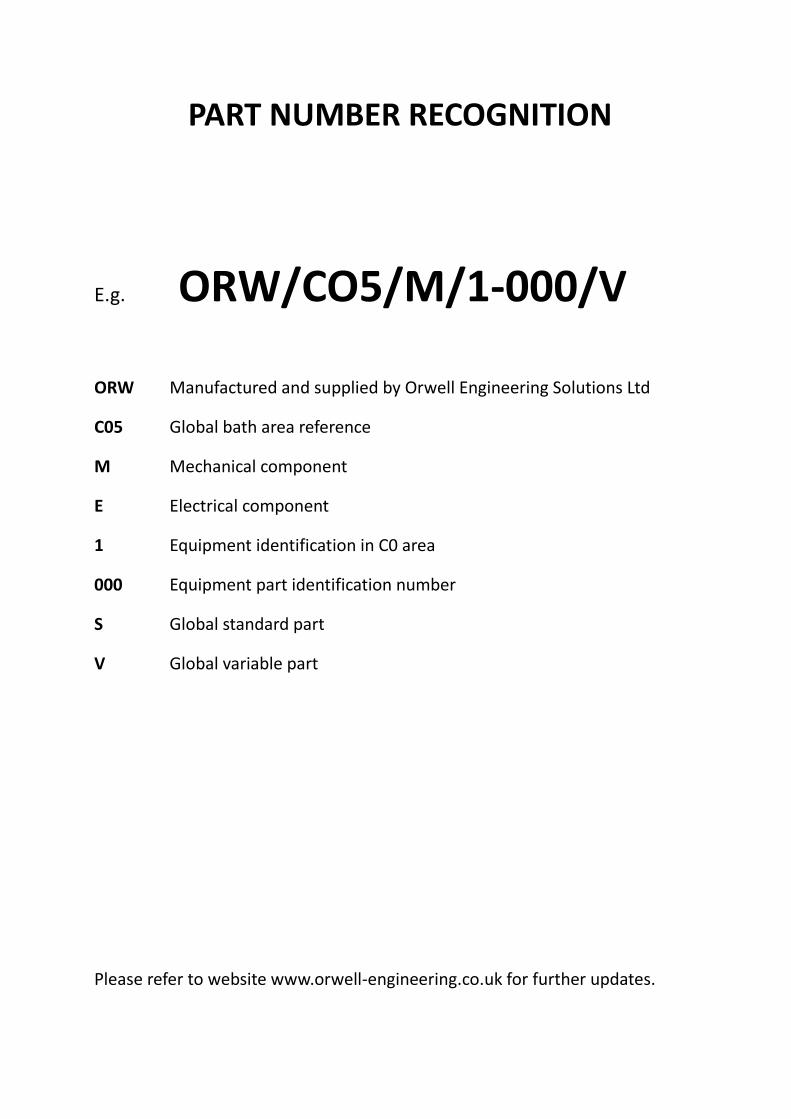
PART NUMBER RECOGNITION
E.g. ORW/CO5/M/1-000/V
ORW Manufactured and supplied by Orwell Engineering Solutions Ltd
C05 Global bath area reference
M Mechanical component
E Electrical component
1 Equipment identification in C0 area
000 Equipment part identification number
S Global standard part
V Global variable part
Please refer to website www.orwell-engineering.co.uk for further updates.

CO1 Complete set of Canal
Equipment

BATH EQUIPMENT
SECTION C01
EQUIPMENT CANAL
PART NUMBER ORW/C01/M/1-000/V
PART NAME COMPLETE CANAL
COMPLETE CANAL
TECHNICAL DESCRIPTION
Orwell can manufacture and supply the complete canal package which will comprise of the canal casing, canal
casing support steelwork, flat arch irons, shut off water box and canal crane (chain operated mobile crane unit).
COMPONENT VARIABLES
There are many variants on the design of the canal equipment. Technical discussions would be necessary and a complete set of the customer’s drawings required for manufacture. Alternatively Orwell can also offer to design the full canal package and supply all components including the refractories.
ADDITIONAL INFORMATION
Technical discussions can be carried out at the Orwell offices in the UK, or our technical directors will travel to you.
Generally there are no steel components on the canal equipment (apart from the flat arch irons and shut off water box) that would be required to be replaced during a glassmaking campaign.

CO1 Spout & Lip Casing

BATH EQUIPMENT
SECTION C01
EQUIPMENT CANAL
PART NUMBER ORW/C01/M/2-000/V
PART NAME SPOUT AND LIP CASING
TECHNICAL DESCRIPTION
Orwell can manufacture and supply the spout and lip casing to customer’s drawings.
COMPONENT VARIABLES
There are many variants on the design of spout and lip casings. Technical discussions would be necessary and a complete set of the customer’s drawings required for manufacture. Alternatively Orwell can also offer to design the spout and lip area and supply the casings complete with the refractory blocks.
ADDITIONAL INFORMATION
Technical discussions can be carried out at the Orwell offices in the UK, or our technical directors will travel to you.
The water boxes of the casings are helium and pressure tested before passing acceptance.

CO1 Complete Tweel Raising Gear

BATH EQUIPMENT
SECTION C01
EQUIPMENT CANAL
PART NUMBER ORW/C01/M/3-000/V
PART NAME COMPLETE TWEEL RAISING GEAR
COMPLETE TWEEL RAISING GEAR
TECHNICAL DESCRIPTION
Orwell can manufacture and supply the complete tweel raising gear package which includes the wiring of the unit,
manufacture and supply of the control panel and electrical testing of the unit prior to despatch.
COMPONENT VARIABLES
There are many variants on the design of the tweel raising gear. Technical discussions would be necessary and a complete set of the customer’s drawings required for manufacture. Alternatively Orwell can manufacture and supply the tweel raising gear to their own in-house design. Orwell can also supply refractory and / or steel tweels.
ADDITIONAL INFORMATION
Technical discussions can be carried out at the Orwell offices in the UK, or our technical directors will travel to you.
Orwell do not carry any items used on the tweel raising gear as stock spares, as it is only in exceptional circumstances that any items would require replacing during a glass making campaign. Orwell can supply individual items for tweel raising gear refurbishment at cold repairs and we can also carry out full refurbishment of tweel raising gear equipment in our premises.

CO3 Exit Lip Plate

BATH EQUIPMENT
SECTION C03
EQUIPMENT BATH CASING
PART NUMBER ORW/C03/M/1-001/V
PART NAME EXIT LIP PLATE
TECHNICAL DESCRIPTION
Orwell can manufacture and supply the exit lip plate including the supply of “Expamet” mesh (for site installation)
and of the special welding rods required (for site welding of the lip plate to the end of the bath casing).
COMPONENT VARIABLES
There are several variants of exit lip plate design. Technical discussions would be necessary and a complete set of the customer’s drawings required for manufacture. Alternatively Orwell can manufacture and supply an exit lip plate to their own in-house design.
ADDITIONAL INFORMATION
Technical discussions can be carried out at the Orwell offices in the UK, or our technical directors will travel to you. Lip plates are packaged for shipment in such a way as to minimise damage due to bending etc. Whilst exit lip plates are not a stock spare carried by Orwell, we can manufacture a lip plate within 4 to 6 weeks of receiving a purchase order and full manufacturing drawings. On a complete new build a spare lip plate is included as part of a standard supply package.
Welds on lip plates are fully dye penetration or X ray tested to customer specification.

CO4 Bath Blocking
Equipment

BATH EQUIPMENT
SECTION C04
EQUIPMENT BATH BLOCKING
PART NUMBER ORW/C04/DS/000/V
PART NAME COMPLETE BATH BLOCKING PACKAGE
TECHNICAL DESCRIPTION
Orwell Engineering Solutions can offer a complete bath blocking packing which includes the design of the bath
blocking and detailing of individual blocks, supply of the bath blocks and supply of all the blocking ancillary items.
In addition Orwell can offer experienced supervisors to be on site to oversee and plan the bath blocking installa-
tion and also a specialist welding engineer to instruct and advise the installation team on the correct use of the
stud welding machine, machine settings and the welding procedures.
ADDITIONAL INFORMATION
The client will be required to arrange the specialised local labour required for blocking installation including equip-
ment to facilitate block handling. In addition the client will be required to identify a specialist local company capa-
ble of block cutting during the installation.
Technical discussions can be carried out at the Orwell offices in the UK, or our technical directors will travel to you
to discuss all aspects of the blocking package.

BATH EQUIPMENT
SECTION C04
EQUIPMENT BATH BLOCKING EQUIPMENT
PART NUMBER ORW/C04/M/1-000/V
PART NAME STUDS/NUTS/WASHERS/CARBON SLEEVES FOR
BATH BLOCKING
TECHNICAL DESCRIPTION
This equipment is used at a new build and a bath repair to secure the bath bottom blocks to the bath
casing.
The studs, nuts and washers are manufactured in heat resisting steel.
The graphite sleeves are manufactured in either CS grade graphite or HLM grade graphite.
The equipment is supplied as a set under the above part number, however items can be supplied indi-
vidually under the following part numbers:-
Nuts - ORW/CO4/M/1-001/S
Studs - ORW/C04/M/1-002/V
Washers – ORW/C04/M/1-003/S
Sleeves - ORW/C04/M/1-004/V
COMPONENT VARIABLES
The studs and graphite sleeves vary in length depending upon the depth of the bath block they are
holding down, The lengths and quantity of each required must be specified by the customer.
ADDITIONAL INFORMATION
Ferrules are automatically included with the supply of studs.
BATH EQUIPMENT
SECTION C04
EQUIPMENT BATH BLOCKING EQUIPMENT
PART NUMBER ORW/C04/M/1-001/S
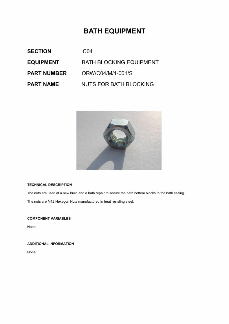
PART NAME NUTS FOR BATH BLOCKING
TECHNICAL DESCRIPTION
The nuts are used at a new build and a bath repair to secure the bath bottom blocks to the bath casing.
The nuts are M12 Hexagon Nuts manufactured in heat resisting steel.
COMPONENT VARIABLES
None
ADDITIONAL INFORMATION
None
BATH EQUIPMENT
SECTION C04
EQUIPMENT BATH BLOCKING EQUIPMENT
PART NUMBER ORW/C04/M/1-002/V
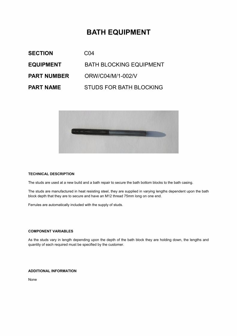
PART NAME STUDS FOR BATH BLOCKING
TECHNICAL DESCRIPTION
The studs are used at a new build and a bath repair to secure the bath bottom blocks to the bath casing.
The studs are manufactured in heat resisting steel, they are supplied in varying lengths dependent upon the bath
block depth that they are to secure and have an M12 thread 75mm long on one end.
Ferrules are automatically included with the supply of studs.
COMPONENT VARIABLES
As the studs vary in length depending upon the depth of the bath block they are holding down, the lengths and
quantity of each required must be specified by the customer.
ADDITIONAL INFORMATION
None
BATH EQUIPMENT
SECTION C04
EQUIPMENT BATH BLOCKING EQUIPMENT
PART NUMBER ORW/C04/M/1-003/S
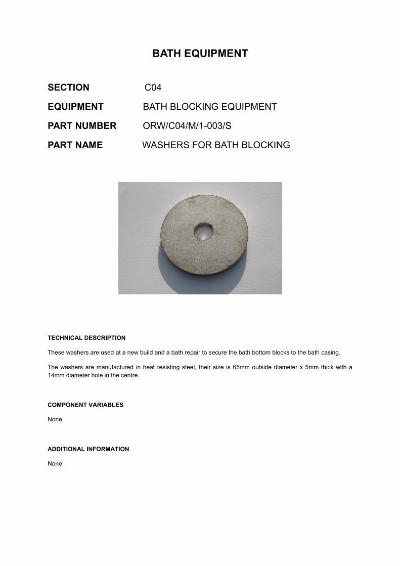
PART NAME WASHERS FOR BATH BLOCKING
TECHNICAL DESCRIPTION
These washers are used at a new build and a bath repair to secure the bath bottom blocks to the bath casing.
The washers are manufactured in heat resisting steel, their size is 65mm outside diameter x 5mm thick with a
14mm diameter hole in the centre.
COMPONENT VARIABLES
None
ADDITIONAL INFORMATION
None

BATH EQUIPMENT
SECTION C04
EQUIPMENT BATH BLOCKING EQUIPMENT
PART NUMBER ORW/C04/M/1-004/V
PART NAME CARBON SLEEVES FOR BATH BLOCKING
TECHNICAL DESCRIPTION
These sleeves are used at a new build and a bath repair and fit around the studs that secure the bath bottom
blocks to the bath casing.
The sleeves are manufactured in either CS grade graphite or HLM grade graphite. They are 32mm outside di-
ameter with a 14mm diameter hole through its whole length. One end of this 14mm diameter hole has a 3mm x
45º chamfer. The sleeve lengths vary dependent upon the bath block depth which they are holding down.
COMPONENT VARIABLES
The graphite sleeves vary in length depending upon the depth of the bath block they are holding down. The
lengths and quantity of each sleeve required must be specified by the customer.
ADDITIONAL INFORMATION
None

BATH EQUIPMENT
SECTION C04
EQUIPMENT BATH GRAPHITE SIDELINERS
PART NUMBER ORW/C04/M/1-005/V
PART NAME SIDELINER STRAPS
TECHNICAL DESCRIPTION
The straps are used to secure the bath graphite sideliners in position.
There are two differing designs of sideliner straps available:
DESIGN ‘A’ – is a ‘T’ shaped strap that is screwed into the graphite sideliner to secure the sideliner in position.
DESIGN ‘B’ – is a straight rectangular bar with a pin through at one end which locates into a hole in the graphite
sideliner, this design relies upon the buoyancy of the sideliner in the tin holding the sideliner in place. This design
allows for the replacing of damaged graphite sideliners “on the run”.
The sideliner straps are manufactured in heat resisting steel grade 304L.
COMPONENT VARIABLES
A manufacturing drawing of the strap required should be provided by the customer along with the quantity re-
quired.
If straps to Design ‘A’ are required the customer should also state if holding down screws are also required.
ADDITIONAL INFORMATION
None

BATH EQUIPMENT
SECTION C04
EQUIPMENT BATH BLOCKING EQUIPMENT
PART NUMBER ORW/C04/M/1-006/S
PART NAME STUD WELDING MACHINE & ANCILLARY ITEMS
TECHNICAL DESCRIPTION
The stud welding machine is an inverter power source which has been developed especially for stud welding. The
machine operates with a 400V, 50/60Hz power supply. The machine comes supplied with the recognised stud
welding gun, cables, specially designed adaptors to fit the studs and operating manual.
ADDITIONAL INFORMATION
A specialist welding engineer can be made available for a site visit to provide training on the stud welding opera-
tion or to carry out full stud welding of the bath blocks.

BATH EQUIPMENT
SECTION C04
EQUIPMENT BATH CARBONS
PART NUMBER ORW/C04/M/1-007/V
PART NAME SIDELINER/BARRIER/FLAG CARBONS
Barrier Carbons
Sideliner Carbon
TECHNICAL DESCRIPTION
Orwell can supply the full package of carbons required for the build of the float bath or spares as required during the glass making campaign.
The carbons are manufactured in either CS grade graphite or HLM grade graphite.
The equipment is supplied as a set under the above part number, however items can be supplied individually under the following part numbers:-
Sideliners - ORW/CO4/M/1-007/A
Barriers - ORW/C04/M/1-007/B
Submerged Flags – ORW/C04/M/1-007/C
Full Depth Flags - ORW/C04/M/1-007/D
COMPONENT VARIABLES
The customer will be required to provide dimensional details of the graphite pieces required. This can be in the form of drawings, sketches or written dimensional sizes.
ADDITIONAL INFORMATION
Due to the many possible dimensional variations, these components are not a stock spare carried by Orwell. Orwell can generally have components available with 8 weeks or earlier.

CO5 Complete Sealed Lehr
BATH EQUIPMENT
SECTION C05
EQUIPMENT SEALED LEHR
PART NUMBER ORW/C05/M/1-000/V
PART NAME COMPLETE SEALED LEHR
COMPLETE SEALED LEHR
TECHNICAL DESCRIPTION
The complete sealed lehr is available to purchase and will comprise of the dross box, hood & drape
raising gear and all ancillary items.
COMPONENT VARIABLES
There are many variants on the complete sealed lehr. Technical discussions would therefore be
necessary.
ADDITIONAL INFORMATION
Technical discussions can be carried out at the Orwell offices in the UK, or our technical directors will
travel to you.

BATH EQUIPMENT
SECTION C05
EQUIPMENT SEALED LEHR
PART NUMBER ORW/C05/M/1-001/V
PART NAME DRAPE
TECHNICAL DESCRIPTION
A drape is a fabricated curtain comprising of a crimped stainless steel corrugated foil secured at the
top between two rolled section angle pieces (25 x 25 x 3) and 25 wide strips of glass fibre tape which
form a flange to allow the drape to sit inside the drape carrier within the sealed lehr hood, and
clamped at each end between steel plates. There are 4 drapes located in the sealed lehr hood one
above each lift out roller and one over the exit lip blocks helping to prevent ingress of oxygen into the
exit end of the bath.
There is also one drape fitted to the front of the lehr above roller No. 4 or 5 (depending upon the lehr
entrance design.
All steel material used on the drape is heat resisting steel grade – 321S31.
COMPONENT VARIABLES
The customer is required to provide a detail drawing of the drape as drapes can vary depending upon
the sealed lehr design.
ADDITIONAL INFORMATION
Due to the environment in which they operate, drapes are a piece of bath equipment that can require
replacing at regular intervals. Bath exit end breaks can also cause damage to drapes resulting in re-
placement being necessary. Unless damaged beyond reasonable re-use, it is normal practice to just
renew the crimped drape material and retain the clamping angles and other plates which secure the
crimped material.
BATH EQUIPMENT
SECTION C05
EQUIPMENT SEALED LEHR
PART NUMBER ORW/C05/M/1-002/V
PART NAME CRIMPED DRAPE MATERIAL
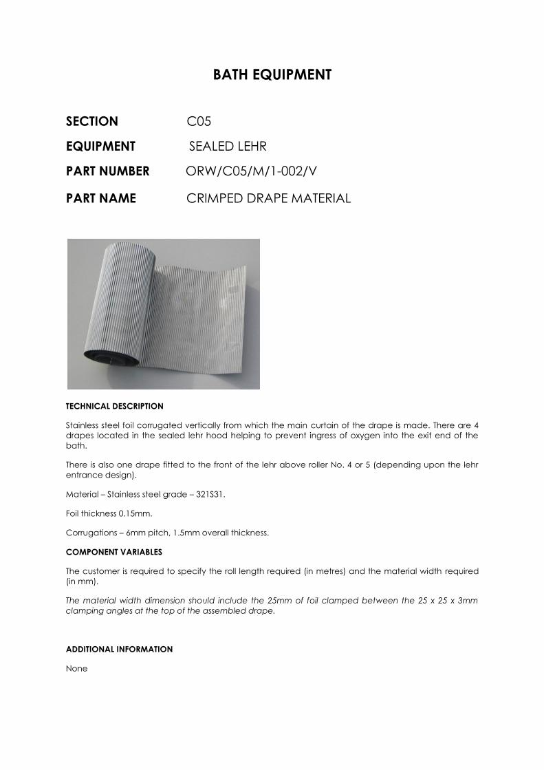
TECHNICAL DESCRIPTION
Stainless steel foil corrugated vertically from which the main curtain of the drape is made. There are 4
drapes located in the sealed lehr hood helping to prevent ingress of oxygen into the exit end of the
bath.
There is also one drape fitted to the front of the lehr above roller No. 4 or 5 (depending upon the lehr
entrance design).
Material – Stainless steel grade – 321S31.
Foil thickness 0.15mm.
Corrugations – 6mm pitch, 1.5mm overall thickness.
COMPONENT VARIABLES
The customer is required to specify the roll length required (in metres) and the material width required
(in mm).
The material width dimension should include the 25mm of foil clamped between the 25 x 25 x 3mm
clamping angles at the top of the assembled drape.
ADDITIONAL INFORMATION
None

BATH EQUIPMENT
SECTION C05
EQUIPMENT SEALED LEHR
PART NUMBER ORW/C05/M/1-003/S
PART NAME LIFT OUT ROLLER BEARING UNIT
(OUT - RIGGER TYPE)
TECHNICAL DESCRIPTION
This bearing unit is a water cooled unit commonly called “out rigger bearing” and is mounted either
side of the dross box on the “L” shaped side plate away from the dross box and supports the lift out
roller.
There are six bearing units on a dross box (two for each lift out roller). The complete unit comes with gun
metal bearings, oil thrower ring, oil filler cap, oil bath drain plug and dipstick.
The bearing housing is water cooled.
All material is mild steel with the exception of the bearing brass which is gun metal BS 1400LG-2C grade.
The finished bearing housing water box is helium leak tested and then hydraulically pressure tested to
6.5 bar. The oil bath housing is leak tested using paraffin.
COMPONENT VARIABLES
This is a standard component. The customer however should confirm the diameter of the lift out roller
journal ends.
ADDITIONAL INFORMATION
The gun metal bearings will over a glassmaking campaign and for a variety of reasons wear out.

BATH EQUIPMENT
SECTION C05
EQUIPMENT SEALED LEHR
PART NUMBER ORW/C05/M/1-005/S
PART NAME LIFT OUT ROLLER BEARING UNIT
(DROSS BOX FLANGE MOUNTED TYPE)
TECHNICAL DESCRIPTION
This bearing unit is bolted to the side plate which is mounted flat against the dross box side and
supports the lift out roller on each side of the dross box.
There are six bearing units (two for each lift out roller). The complete unit comes with gun metal
bearings, oil thrower, oil bath drain plug and dipstick.
The bearing housing is water cooled.
All material is mild steel with the exception of the bearing brass which is gun metal BS 1400LG-2C grade.
The finished bearing housing water box is helium leak tested and then hydraulically pressure tested to
6.5 bar. The oil bath housing is leak tested using paraffin.
COMPONENT VARIABLES
This is a standard component.
ADDITIONAL INFORMATION
The gun metal bearings will over a glassmaking campaign and for a variety of reasons wear out.

BATH EQUIPMENT
SECTION C05
EQUIPMENT SEALED LEHR
PART NUMBER ORW/C05/M/1-006/S
PART NAME SOLID GUN METAL BEARING BRASSES
(DROSS BOX FLANGE MOUNTED TYPE)
TECHNICAL DESCRIPTION
The bearing brasses are solid one piece brasses for use in the flange mounted housing.
Gun metal bearing material – Grade BS 1400LG-2C
The inside diameter of the bearing brass is 108.108/108.054mm.
COMPONENT VARIABLES
This is a standard component, however if required by the customer the inside diameter can be
machined to a different tolerance than that shown above. In such cases the customer should specify
the change when ordering.
ADDITIONAL INFORMATION
The gun metal bearings will over a glassmaking campaign and for a variety of reasons wear out.

BATH EQUIPMENT
SECTION C05
EQUIPMENT SEALED LEHR
PART NUMBER ORW/C05/M/1-007/S
PART NAME LIFT OUT ROLLER BEARING OIL THROWER
TECHNICAL DESCRIPTION
The oil thrower is a mild steel ring that can be split for assembly and fits through the bearing brass. As
the thrower rotates it drags oil from the bearing housing oil bath and lubricates the brass bearing.
Oil ring outside diameter – 156mm
Oil ring inside diameter – 150mm
Oil ring width – 10mm
COMPONENT VARIABLES
This is a standard component.
ADDITIONAL INFORMATION
The thrower is the same for both the outrigger and flange mounted bearings.

BATH EQUIPMENT
SECTION C05
EQUIPMENT SEALED LEHR
PART NUMBER ORW/C05/M/1-008/S
PART NAME COMPRESSION SPRINGS
TECHNICAL DESCRIPTION
The compression springs form part of the lift out roller installation assembly and they are located inside
the dross box side plate and by means of retaining and pressure plates are used to push the lift out
roller end face carbon seal up against the roller body end. There are two compression springs on each
side of the lift out roller.
Compression spring material – Inconel X750
Spring inside diameters – 175mm & 150mm
Spring wire diameter – 4.76mm
Spring length – 150mm free length
Number of coils – 9
COMPONENT VARIABLES
This is a standard component.
ADDITIONAL INFORMATION
The springs will over a glassmaking campaign due to the environment in which they are operating in
lose some of their compression strength and require replacing. Older plants may have springs made
from Nimonic 90, this material has now been superseded by Inconel X750.

BATH EQUIPMENT
SECTION C05
EQUIPMENT SEALED LEHR
PART NUMBER ORW/C05/M/1-009/V
PART NAME LEAF SPRING ASSEMBLY
Leaf spring assembly Individual springs
TECHNICAL DESCRIPTION
The leaf springs assembly is installed generally beneath lift out roller Nos.1 & 2 in the cast iron channel
section. Carbon face seals sit on top of the leaf springs such that the thrust of the leaf spring pushes the
face seal up against the roller body.
Leaf spring material – heat resisting steel 304L
Steel thickness – 2.64mm
Spring thrust - ~ 9 Kg
Note :- In addition to supplying full leaf spring assemblies, Orwell can also supply the individual springs
(single & double) which the customer can then rivet themselves to an existing backing strip. This
method may be more attractive to the customer as it keeps packing and carriage costs to a minimum.
To order just individual springs please quote the following part numbers :-
ORW/C05/M/1-009/A – for the single spring
ORW/C05/M/1-009/B – for the double spring
COMPONENT VARIABLES
Whilst the individual spring detail is standard (single and double springs), a detail drawing of the leaf
spring assembly giving the overall length of the spring backing plate and the spring fixing hole
configuration is required from the customer.
ADDITIONAL INFORMATION
The springs will over a glassmaking campaign due to the environment in which they are operating in
lose some of their thrust strength and will require replacing. Springs used to be manufactured in stainless
steel 321S31 but this is no longer available.
BATH EQUIPMENT
SECTION C05
EQUIPMENT SEALED LEHR
PART NUMBER ORW/C05/M/1-010/S
PART NAME BELLOWS UNIT ASSEMBLY
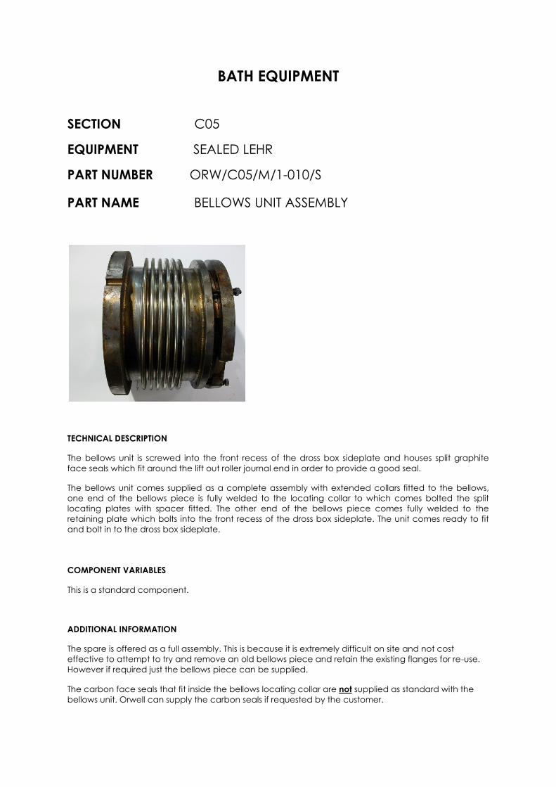
TECHNICAL DESCRIPTION
The bellows unit is screwed into the front recess of the dross box sideplate and houses split graphite
face seals which fit around the lift out roller journal end in order to provide a good seal.
The bellows unit comes supplied as a complete assembly with extended collars fitted to the bellows,
one end of the bellows piece is fully welded to the locating collar to which comes bolted the split
locating plates with spacer fitted. The other end of the bellows piece comes fully welded to the
retaining plate which bolts into the front recess of the dross box sideplate. The unit comes ready to fit
and bolt in to the dross box sideplate.
COMPONENT VARIABLES
This is a standard component.
ADDITIONAL INFORMATION
The spare is offered as a full assembly. This is because it is extremely difficult on site and not cost
effective to attempt to try and remove an old bellows piece and retain the existing flanges for re-use.
However if required just the bellows piece can be supplied.
The carbon face seals that fit inside the bellows locating collar are not supplied as standard with the
bellows unit. Orwell can supply the carbon seals if requested by the customer.
BATH EQUIPMENT
SECTION C05
EQUIPMENT SEALED LEHR
PART NUMBER ORW/C05/M/1-011/V
PART NAME HAIRPIN COOLER
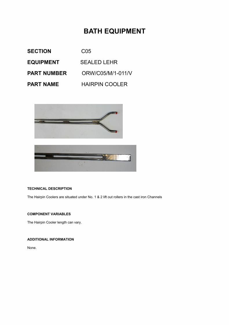
TECHNICAL DESCRIPTION
The Hairpin Coolers are situated under No. 1 & 2 lift out rollers in the cast iron Channels
COMPONENT VARIABLES
The Hairpin Cooler length can vary.
ADDITIONAL INFORMATION
None.

BATH EQUIPMENT
SECTION C05
EQUIPMENT SEALED LEHR
PART NUMBER ORW/C05/M/1-012/V
PART NAME CAST IRON CHANNEL SEALING COPPER GASKETS
TECHNICAL DESCRIPTION
The Copper Gaskets form the seal between the end of the cast iron channels and the Dross Box End Plates.
COMPONENT VARIABLES
The dimensions of the copper gasket can differ between different size dross boxes. Therefore a drawing or sketch
would be required.
ADDIONAL INFORMATION
None.

BATH EQUIPMENT
SECTION C05
EQUIPMENT SEALED LEHR
PART NUMBER ORW/C05/M/1-013/V
PART NAME MILD STEEL SEALING PLATES
TECHNICAL DESCRIPTION
Along with the Copper Gaskets, the mild steel plates form the seal between the cast iron channels and
the Dross Box end plates.
COMPONENT VARIABLES
The dimensions of the steel plates can differ between different sized Dross Boxes. Therefore a drawing or
sketch would be required.
ADDITIONAL INFORMATION
None.
BATH EQUIPMENT
SECTION C05
EQUIPMENT SEALED LEHR
PART NUMBER ORW/C05/M/1-014/V
PART NAME BEARING MOUNTING FACE PLATE
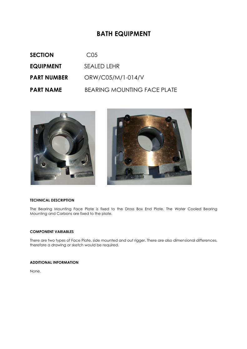
TECHNICAL DESCRIPTION
The Bearing Mounting Face Plate is fixed to the Dross Box End Plate. The Water Cooled Bearing
Mounting and Carbons are fixed to the plate.
COMPONENT VARIABLES
There are two types of Face Plate, side mounted and out rigger. There are also dimensional differences,
therefore a drawing or sketch would be required.
ADDITIONAL INFORMATION
None.
BATH EQUIPMENT
SECTION C05
EQUIPMENT SEALED LEHR
PART NUMBER ORW/C05/M/1-015/V
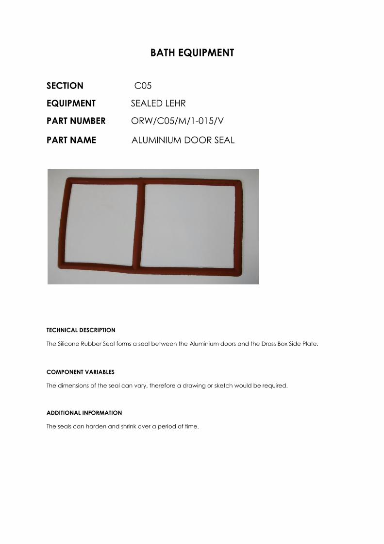
PART NAME ALUMINIUM DOOR SEAL
TECHNICAL DESCRIPTION
The Silicone Rubber Seal forms a seal between the Aluminium doors and the Dross Box Side Plate.
COMPONENT VARIABLES
The dimensions of the seal can vary, therefore a drawing or sketch would be required.
ADDITIONAL INFORMATION
The seals can harden and shrink over a period of time.

BATH EQUIPMENT
SECTION C05
EQUIPMENT SEALED LEHR
PART NUMBER ORW/C05/M/1-016/V
PART NAME DROSS BOX ALUMINIUM DOORS
TECHNICAL DESCRIPTION
The Dross Box doors enclose the chambers at the end of the unit.
COMPONENT VARIABLES
The dimensions of the Aluminium Doors can vary, therefore a drawing or sketch would be required.
ADDITIONAL INFORMATION
None.
BATH EQUIPMENT
SECTION C05
EQUIPMENT SEALED LEHR
PART NUMBER ORW/C05/M/1-017/V
PART NAME DROSS BOX CHANNELS
TECHNICAL DESCRIPTION
These dross box channels are designed to be replaceable should the need arise and are bolted from
the underside of the dross box into the steel fabricated sections inside the dross box beneath each lift
out roller. The channels form the housing into which the leaf springs and lift out roller sealing graphites
are fitted. The channels are one piece cast iron grade BS250 and are machined to the customers
drawing specification.
COMPONENT VARIABLES
The channels will vary in length and depth depending upon the dross box size and design. A
manufacturing drawing would be required from the customer.
ADDITIONAL INFORMATION
The customer should state whether holding down bolts and washers are also required.

CO5 Lift Out Roller Drive Unit

BATH EQUIPMENT
SECTION C05
EQUIPMENT LIFT OUT ROLLER DRIVE
PART NUMBER ORW/C05/M/2-000/V
PART NAME LIFT OUT ROLLER UNIT
LIFT OUT ROLLER
DRIVE UNIT
TECHNICAL DESCRIPTION
The mechanical lift out roller drive situated in the Lehr Gap area driving No 1, 2 & 3 Lift out rollers.
COMPONENT VARIABLES
There are many variants on the complete Lift Out Roller Drive. Technical discussions would therefore be
necessary.
ADDITIONAL INFORMATION
Technical discussions can be carried out at the Orwell offices in the UK, or our technical directors will
travel to you.

BATH EQUIPMENT
SECTION C05
EQUIPMENT LIFT OUT ROLLER DRIVE
PART NUMBER ORW/C05/M/2-001/V
PART NAME DRIVE SHAFT TO LIFT OUT ROLLER
TECHNICAL DESCRIPTION
The drive shaft forms and facilitates the connection between the roller drive gearbox on the lift out
roller drive unit and the lift out roller journal. The drive shaft is a “Hardy Spicer” heavy duty prop shaft
type BRD 52 Reference No. 52 AE 02 – compressed length 475mm.
COMPONENT VARIABLES
The customer is required when ordering to confirm the compressed length as 475mm.
ADDITIONAL INFORMATION
None

BATH EQUIPMENT
SECTION C05
EQUIPMENT LIFT OUT ROLLER DRIVE
PART NUMBER ORW/C05/M/2-002/V
PART NAME DRIVE SHAFT FROM LEHR DRIVE
TECHNICAL DESCRIPTION
The drive shaft forms and facilitates the connection between the lehr drive transfer gearbox and the lift
out roller drive unit. The drive shaft is a “Hardy Spicer” heavy duty prop shaft type BRD 62 Reference
No.62 AE 01.
COMPONENT VARIABLES
The customer is required to provide a detail drawing of the drive shaft showing the minimum and
maximum compressive lengths and also showing the flange details at each end of the drive shaft.
ADDITIONAL INFORMATION
None

BATH EQUIPMENT
SECTION C05
EQUIPMENT LIFT OUT ROLLER DRIVE
PART NUMBER ORW/C05/M/2-003/V
PART NAME RENOLDS GEARBOX
TECHNICAL DESCRIPTION
A new “Renold” gearbox Reference UO 35 is only available on a long delivery schedule (approximately
20 weeks) at standard cost. Orwell can however obtain new gearboxes within approximately 13 weeks
but this comes at a cost premium (up to date cost comparisons on request). Orwell can also offer to
supply a refurbishment kit of new worm and wheels, bearings and oil seals for our customers to refurbish
their existing gearboxes. These kits are available on an 8 week delivery.
The gearbox is a “Renold” UO 35 overdriven type left hand or right hand assembly.
COMPONENT VARIABLES
The customer is required to specify whether the gearbox required is a left hand assembly (assembly 11)
or a right hand assembly (assembly 12).
ADDITIONAL INFORMATION
None

CO6 Complete Side
Sealing Package

BATH EQUIPMENT
SECTION C06
EQUIPMENT SIDE SEALING
PART NUMBER ORW/C06/M/1-000/V
PART NAME COMPLETE SIDE SEALING PACKAGE
Selection of Typical Side Seals
TECHNICAL DESCRIPTION
The side sealing package provides a complete sealing system between the bath and roof casings. Orwell can
manufacture and supply all shapes and sizes of side seals to the customer’s manufacturing drawings.
COMPONENT VARIABLES
There are many variants on side seal. Technical discussions would therefore be necessary.
ADDITIONAL INFORMATION
Technical discussions can be carried out at the Orwell offices in the UK, or our technical directors will travel to
you.

BATH EQUIPMENT
SECTION C06
EQUIPMENT SIDE SEALING
PART NUMBER ORW/C06/M/1-001/S
PART NAME TIN THERMOCOUPLE SAMPLE POINT
SILICONE GLAND
TECHNICAL DESCRIPTION
These seals are used on the tin thermocouple side seal to seal around the thermocouple stem on
installation through the seal.
A moulded cylindrical silicone rubber seal.
Seal diameter = 67mm & 44mm.
Bore diameter = 19mm.
Counterbore = 52mm diameter x 16mm deep.
Overall length = 41mm with 22mm shoulder.
COMPONENT VARIABLES
This is a standard component.
ADDITIONAL INFORMATION
The physical dimensions of the gland may vary slightly due to shrinkage over a period of time, this is
normal.

BATH EQUIPMENT
SECTION C06
EQUIPMENT SIDE SEALING
PART NUMBER ORW/C06/M/1-002/S
PART NAME TIN THERMOCOUPLE PROBE SOCKETS
TECHNICAL DESCRIPTION
These sockets are used on the tin thermocouple and tin / oxygen probe side seals. They are screwed
onto the boss around the side seal inlet to provide a mating surface for the silicone seal gland to seal
up against.
Material used mild steel.
Socket outside diameter = 52mm.
Socket bore diameter = 1¼” BSP thread.
Overall length = 50mm.
COMPONENT VARIABLES
This is a standard component.
ADDITIONAL INFORMATION
None
BATH EQUIPMENT
SECTION C06
EQUIPMENT SIDE SEALING
PART NUMBER ORW/C06/M/1-003/S
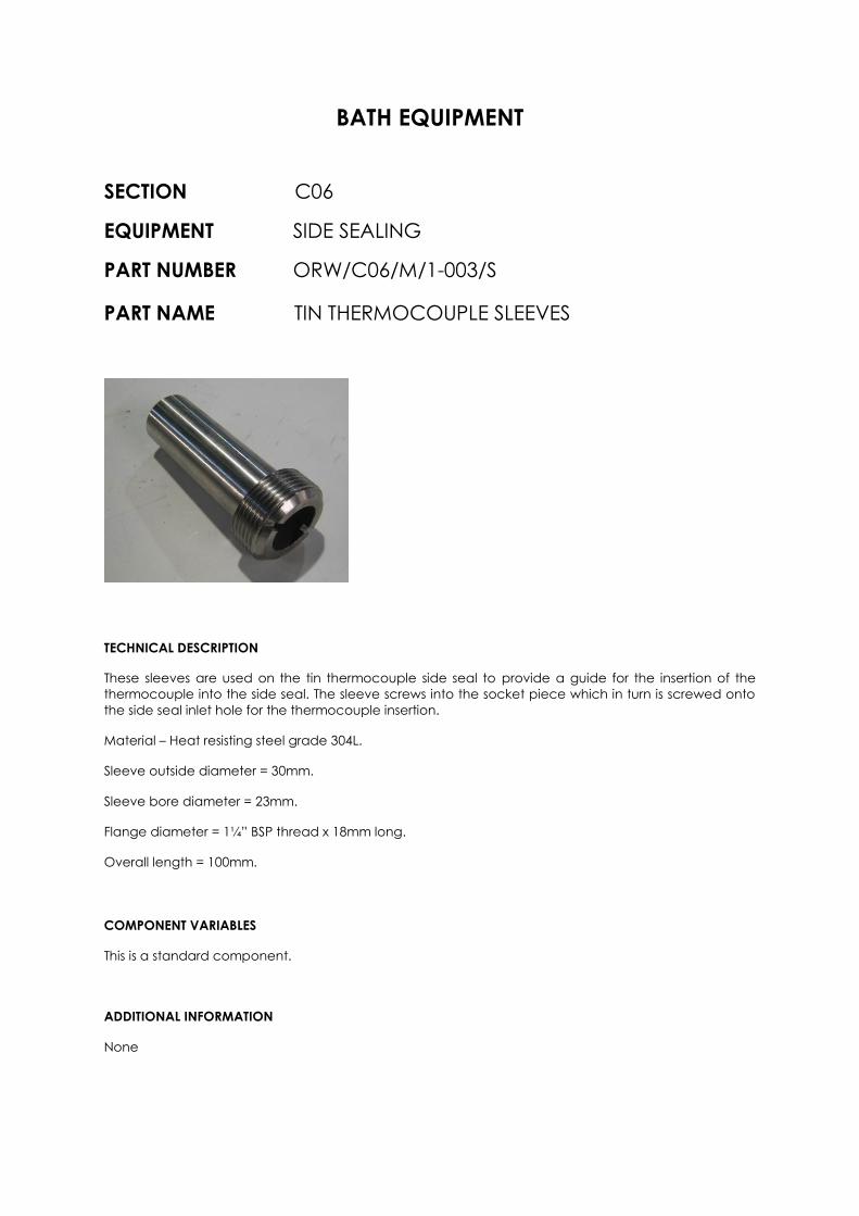
PART NAME TIN THERMOCOUPLE SLEEVES
TECHNICAL DESCRIPTION
These sleeves are used on the tin thermocouple side seal to provide a guide for the insertion of the
thermocouple into the side seal. The sleeve screws into the socket piece which in turn is screwed onto
the side seal inlet hole for the thermocouple insertion.
Material – Heat resisting steel grade 304L.
Sleeve outside diameter = 30mm.
Sleeve bore diameter = 23mm.
Flange diameter = 1¼” BSP thread x 18mm long.
Overall length = 100mm.
COMPONENT VARIABLES
This is a standard component.
ADDITIONAL INFORMATION
None

BATH EQUIPMENT
SECTION C06
EQUIPMENT SIDE SEALING
PART NUMBER ORW/C06/M/1-004/S
PART NAME TIN/OXYGEN PROBE SILICONE GLAND SEAL
TECHNICAL DESCRIPTION
These seals are used on the tin / oxygen side seal to seal around the tin / oxygen probe stem on
installation through the seal.
A moulded cylindrical silicone rubber seal.
Seal diameter = 67 & 44mm.
Bore diameter = 28mm.
Counterbore = 52mm diameter x 16 deep.
Overall length = 41mm with 22mm shoulder.
COMPONENT VARIABLES
This is a standard component.
ADDITIONAL INFORMATION
The physical dimensions of the gland may vary slightly due to shrinkage over a period of time, this is
normal.
BATH EQUIPMENT
SECTION C06
EQUIPMENT SIDE SEALING
PART NUMBER ORW/C06/M/1-005/S
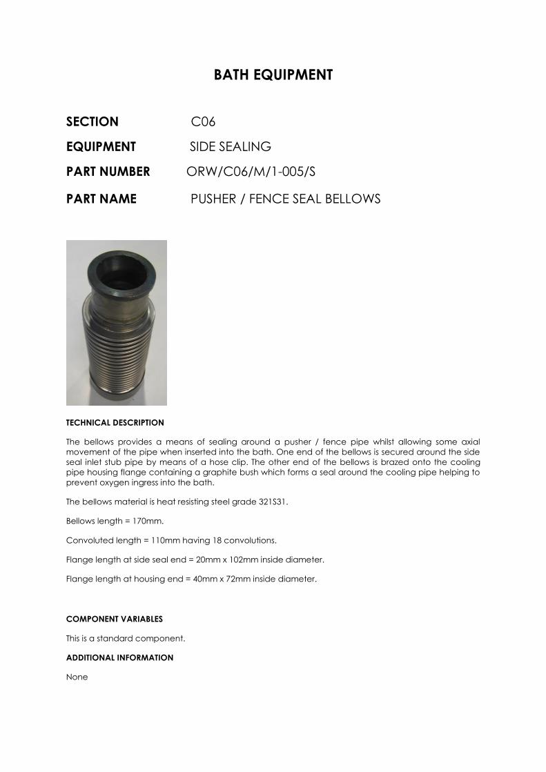
PART NAME PUSHER / FENCE SEAL BELLOWS
TECHNICAL DESCRIPTION
The bellows provides a means of sealing around a pusher / fence pipe whilst allowing some axial
movement of the pipe when inserted into the bath. One end of the bellows is secured around the side
seal inlet stub pipe by means of a hose clip. The other end of the bellows is brazed onto the cooling
pipe housing flange containing a graphite bush which forms a seal around the cooling pipe helping to
prevent oxygen ingress into the bath.
The bellows material is heat resisting steel grade 321S31.
Bellows length = 170mm.
Convoluted length = 110mm having 18 convolutions.
Flange length at side seal end = 20mm x 102mm inside diameter.
Flange length at housing end = 40mm x 72mm inside diameter.
COMPONENT VARIABLES
This is a standard component.
ADDITIONAL INFORMATION
None
BATH EQUIPMENT
SECTION C06
EQUIPMENT SIDE SEALING
PART NUMBER ORW/C06/M/1-006/V
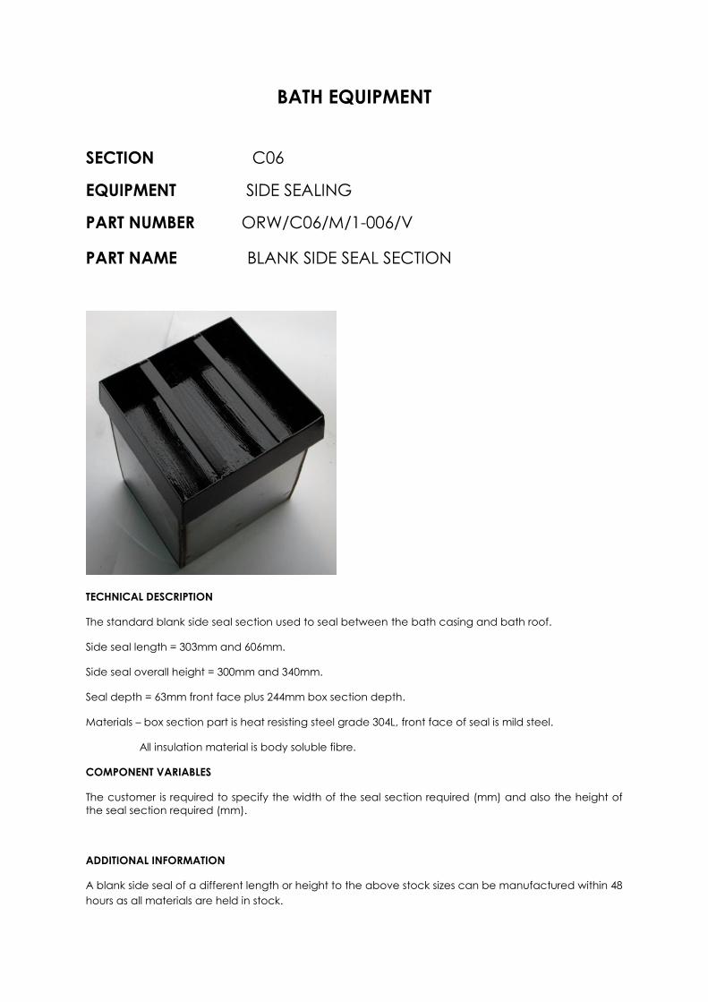
PART NAME BLANK SIDE SEAL SECTION
TECHNICAL DESCRIPTION
The standard blank side seal section used to seal between the bath casing and bath roof.
Side seal length = 303mm and 606mm.
Side seal overall height = 300mm and 340mm.
Seal depth = 63mm front face plus 244mm box section depth.
Materials – box section part is heat resisting steel grade 304L, front face of seal is mild steel.
All insulation material is body soluble fibre.
COMPONENT VARIABLES
The customer is required to specify the width of the seal section required (mm) and also the height of
the seal section required (mm).
ADDITIONAL INFORMATION
A blank side seal of a different length or height to the above stock sizes can be manufactured within 48
hours as all materials are held in stock.
BATH EQUIPMENT
SECTION C06
EQUIPMENT SIDE SEALING
PART NUMBER ORW/C06/M/1-007/S
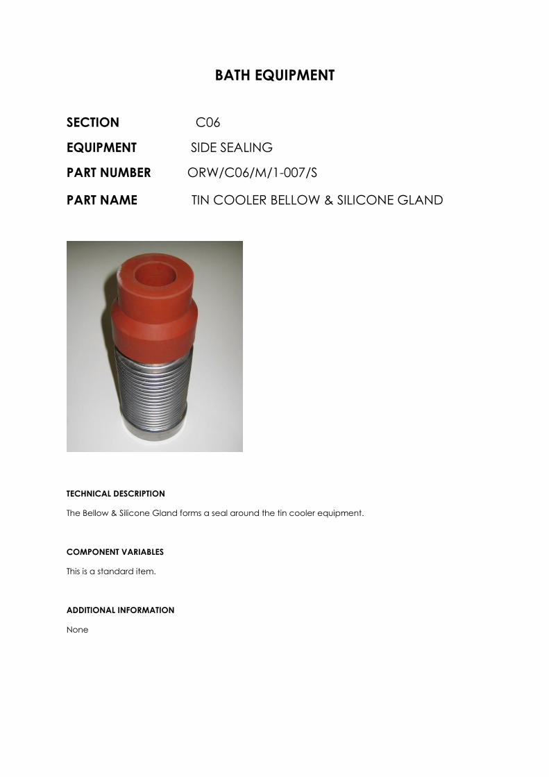
PART NAME TIN COOLER BELLOW & SILICONE GLAND
TECHNICAL DESCRIPTION
The Bellow & Silicone Gland forms a seal around the tin cooler equipment.
COMPONENT VARIABLES
This is a standard item.
ADDITIONAL INFORMATION
None

CO6 Motorised
Positioner Units
BATH EQUIPMENT
SECTION C06
EQUIPMENT MOTORISED POSITIONER UNIT
PART NUMBER ORW/C06/M/2-000/V
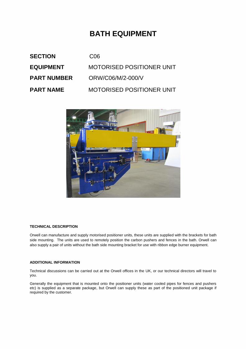
PART NAME MOTORISED POSITIONER UNIT
TECHNICAL DESCRIPTION
Orwell can manufacture and supply motorised positioner units, these units are supplied with the brackets for bath
side mounting. The units are used to remotely position the carbon pushers and fences in the bath. Orwell can
also supply a pair of units without the bath side mounting bracket for use with ribbon edge burner equipment.
ADDITIONAL INFORMATION
Technical discussions can be carried out at the Orwell offices in the UK, or our technical directors will travel to you.
Generally the equipment that is mounted onto the positioner units (water cooled pipes for fences and pushers etc) is supplied as a separate package, but Orwell can supply these as part of the positioned unit package if required by the customer.

BATH EQUIPMENT
SECTION C06
EQUIPMENT MOTORISED POSITIONER UNIT
PART NUMBER ORW/C06/M/2-001/S
PART NAME AIR MOTOR
TECHNICAL DESCRIPTION
The air motor drives the carriage of the motorised positioner unit onto which the pusher or fence units are mounted enabling the pushes and fences to be remotely positioned relative to the glass ribbon inside of the bath. The air motor is a ‘Gast’ motor reversible type reference 1UP-NRV-10.
ADDITIONAL INFORMATION
The air motor is not a standard stock spare item held by Orwell, but Orwell can generally have one available within 6 weeks or earlier.

BATH EQUIPMENT
SECTION C06
EQUIPMENT MOTORISED POSITIONER UNIT
PART NUMBER ORW/C06/M/2-002/V
PART NAME PNEUMATIC SPARES
Poppet valves Spool valve
Solenoid valves
Shuttle valves
TECHNICAL DESCRIPTION
The pneumatic circuit of the positioner units contain a variety of valves (spool, poppet shuttle and solenoid). The components are very robust and failure of these items is very unlikely in a glass making campaign. These items are not carried as stock spares by Orwell, but Orwell can generally supply spares within 4 weeks or earlier.
ADDITIONAL INFORMATION
The particular spare will required to be clearly identified, each valve has a model number marked on it for ease of identification.

BATH EQUIPMENT
SECTION C06
EQUIPMENT MOTORISED POSITIONER UNIT
PART NUMBER ORW/C06/M/2-003/S
PART NAME FILTER/REGULATOR/LUBRICATOR
TECHNICAL DESCRIPTION
Mounted on the positioner unit pneumatic panel, the filter/regulator/lubricator assembly cleans, controls and lubricates the incoming compressed air into the pneumatic system of the positioned unit.
COMPONENT VARIABLES
None
ADDITIONAL INFORMATION
The filter/regulator/lubricator assembly is not a standard stock spare item held by Orwell, but Orwell can generally have one available within 4 weeks or earlier.

CO6 Section ‘O’
Sealing Frame

BATH EQUIPMENT
SECTION C06
EQUIPMENT BATH SIDE SEALING
PART NUMBER ORW/C06/M/3-000/V
PART NAME FRONT LINTEL SEALING FRAME
COMPLETE FRAME AND
SUPPORTING STEELWORK
TECHNICAL DESCRIPTION
The front lintel sealing frame is attached to the bath roof casing and forms a seal upstream of the front roof lintel
in the area commonly referred to as “Section O”. The frame is a steel fabricated structure that is fully welded to
the bath roof casing. The frame houses refractory blocks which are designed to fit and seal around the bath roof
inlet lintel.
COMPONENT VARIABLES
Orwell can manufacture to the customer’s design drawings, or alternatively Orwell can offer their own in-house design for this unit.
ADDITIONAL INFORMATION
Technical discussions can be carried out at the Orwell offices in the UK, or our technical directors will travel to you.
The supply of the refractory blocks by Orwell is optional.

CO7 Bath Coolers

BATH EQUIPMENT
SECTION C07
EQUIPMENT OVERHEAD COOLERS
PART NUMBER ORW/C07/M/1-000/V
PART NAME BATH COOLERS
COMPLETE SET OF COOLERS
FOR USE IN THE BATH
TECHNICAL DESCRIPTION
Orwell can manufacture and supply all types of coolers used in the float bath (hot end rail coolers, hot end split
banjo coolers, narrow end parallel coolers and narrow end banjo coolers) for new builds and cold repairs. The
coolers are manufactured to customer’s manufacturing drawings and can be supplied with helium and pressure
test certificates (on request).
COMPONENT VARIABLES
There are several variants on the design of bath coolers. Technical discussions would be necessary and a complete set of the customer’s drawings required for manufacture.
ADDITIONAL INFORMATION
Technical discussions can be carried out at the Orwell offices in the UK, or our technical directors will travel to you.
Orwell can test coolers to customer’s specifications, generally Orwell helium leak test and pressure test all coolers prior to despatch.
There are generally no spares associated with coolers and Orwell do not carry coolers as a spares stock item due to design variances. Replacement individual coolers can be manufactured by Orwell within 10 working days or earlier of receiving a customer’s official purchase order and manufacturing drawings dependent upon the quantity required.

CO7 Hot End
Cooler Carriages

BATH EQUIPMENT
SECTION C07
EQUIPMENT OVERHEAD COOLERS
PART NUMBER ORW/C07/M/2-000/V
PART NAME HOT END COOLER CARRIAGES
TECHNICAL DESCRIPTION
Orwell can manufacture and supply hot end overhead cooler carriages and support steelwork for new builds and
cold repairs. This equipment is sited in Bays 1 & 2 on both sides of the bath.
COMPONENT VARIABLES
There are several variants on the design of hot end cooler carriages and the supporting steelwork. Technical discussions would be necessary and a complete set of the customer’s drawings required for manufacture. Alternatively Orwell can offer their own in-house design of these cooler carriages and supporting steelwork. Technical discussions would also be required to co-ordinate the design with the customer’s bath supporting steelwork design.
ADDITIONAL INFORMATION
Technical discussions can be carried out at the Orwell offices in the UK, or our technical directors will travel to you.
There are generally no spares associated with hot end carriages or the support steelwork, manufacturing and delivery time would be agreed with the customer.

CO7 Narrow End
Cooler Carriages
BATH EQUIPMENT
SECTION C07
EQUIPMENT OVERHEAD COOLERS
PART NUMBER ORW/C07/M/3-000/V
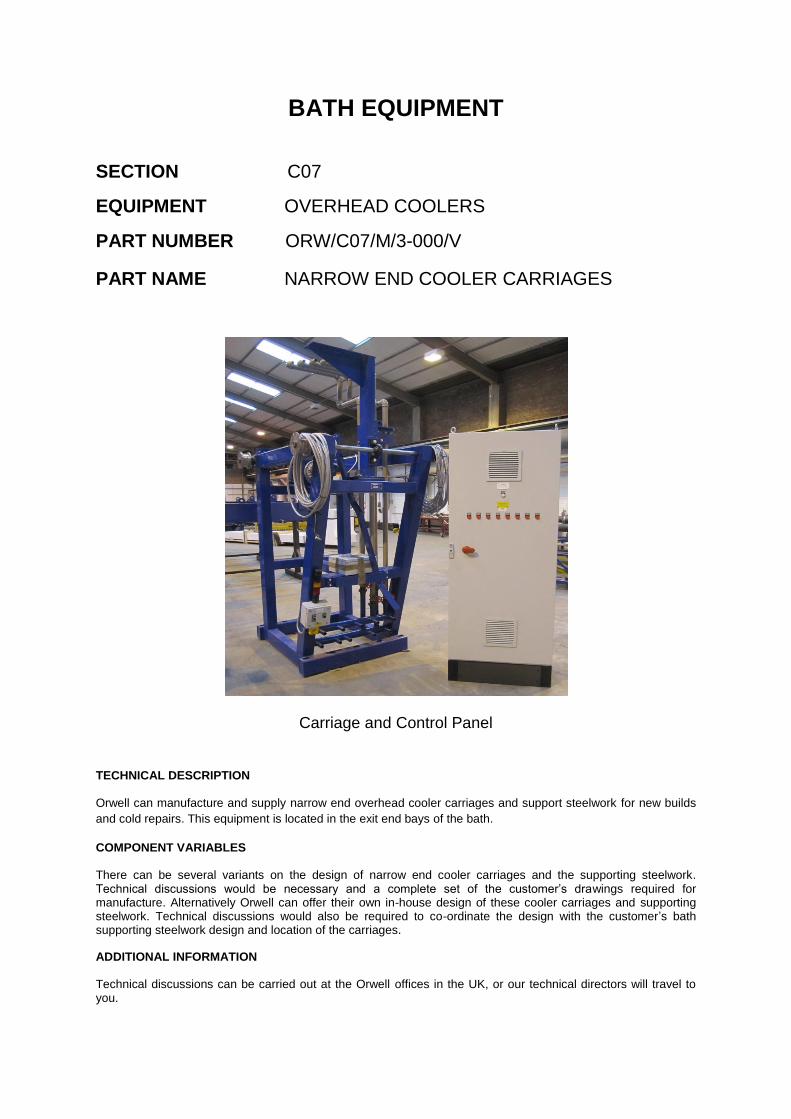
PART NAME NARROW END COOLER CARRIAGES
Carriage and Control Panel
TECHNICAL DESCRIPTION
Orwell can manufacture and supply narrow end overhead cooler carriages and support steelwork for new builds
and cold repairs. This equipment is located in the exit end bays of the bath.
COMPONENT VARIABLES
There can be several variants on the design of narrow end cooler carriages and the supporting steelwork. Technical discussions would be necessary and a complete set of the customer’s drawings required for manufacture. Alternatively Orwell can offer their own in-house design of these cooler carriages and supporting steelwork. Technical discussions would also be required to co-ordinate the design with the customer’s bath supporting steelwork design and location of the carriages.
ADDITIONAL INFORMATION
Technical discussions can be carried out at the Orwell offices in the UK, or our technical directors will travel to you.

BATH EQUIPMENT
SECTION C07
EQUIPMENT OVERHEAD COOLERS
PART NUMBER ORW/C07/M/3-001/S
PART NAME NARROW END CARRIAGE GEARBOX
TECHNICAL DESCRIPTION
The gearbox forms part of the drive arrangement to the carriage. The gearbox is a ‘Renold’ WM 5 shaft mounted
box.
COMPONENT VARIABLES
This is a standard component.
ADDITIONAL INFORMATION
The gearbox is not a standard stock spare item held by Orwell, but Orwell can generally have one available within 6 weeks or earlier.
BATH EQUIPMENT
SECTION C07
EQUIPMENT OVERHEAD COOLERS
PART NUMBER ORW/C07/M/3-002/S
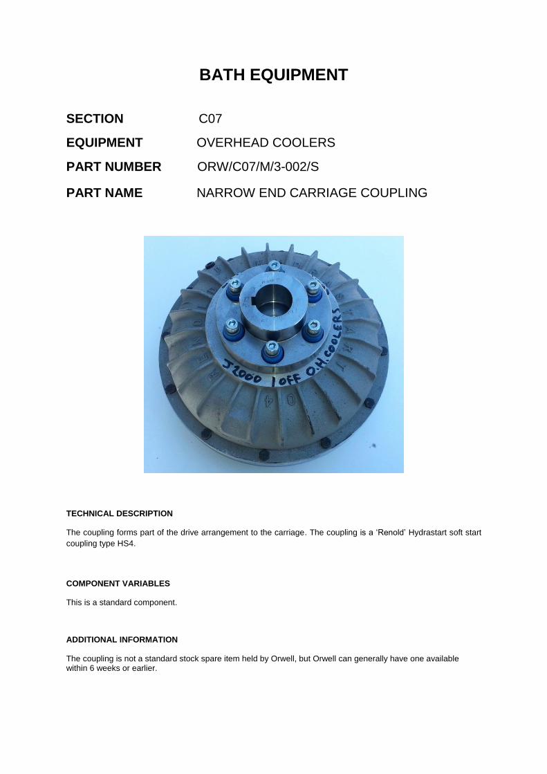
PART NAME NARROW END CARRIAGE COUPLING
TECHNICAL DESCRIPTION
The coupling forms part of the drive arrangement to the carriage. The coupling is a ‘Renold’ Hydrastart soft start
coupling type HS4.
COMPONENT VARIABLES
This is a standard component.
ADDITIONAL INFORMATION
The coupling is not a standard stock spare item held by Orwell, but Orwell can generally have one available within 6 weeks or earlier.
BATH EQUIPMENT
SECTION C07
EQUIPMENT OVERHEAD COOLERS
PART NUMBER ORW/C07/M/3-003/S
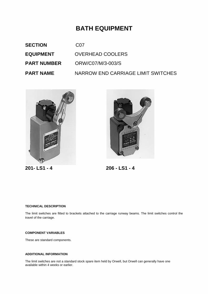
PART NAME NARROW END CARRIAGE LIMIT SWITCHES
201- LS1 - 4 206 - LS1 - 4
TECHNICAL DESCRIPTION
The limit switches are fitted to brackets attached to the carriage runway beams. The limit switches control the
travel of the carriage.
COMPONENT VARIABLES
These are standard components.
ADDITIONAL INFORMATION
The limit switches are not a standard stock spare item held by Orwell, but Orwell can generally have one available within 4 weeks or earlier.

CO7 Floor Mounted
Cooler Carriages

BATH EQUIPMENT
SECTION C07
EQUIPMENT OVERHEAD COOLERS
PART NUMBER ORW/C07/M/4-000/V
PART NAME FLOOR MOUNTED OVERHEAD
COOLER CARRIAGES
TECHNICAL DESCRIPTION
Orwell can manufacture and supply manually operated floor mounted overhead cooler carriages. The carriages
are manufactured and supplied in pairs and can be supplied with or without the coolers and special bath side seal
depending upon the customer’s needs.
COMPONENT VARIABLES
There are several variants on the design of carriages, cooler and side seal. Technical discussions would be necessary and a complete set of the customer’s drawings required for manufacture. Alternatively Orwell can offer their own in-house design of these carriages.
ADDITIONAL INFORMATION
Technical discussions can be carried out at the Orwell offices in the UK, or our technical directors will travel to you.

CO8 Linear Motor
Carriages
BATH EQUIPMENT
SECTION C08
EQUIPMENT LINEAR MOTOR CARRIAGES
PART NUMBER ORW/C08/M/1-000/S
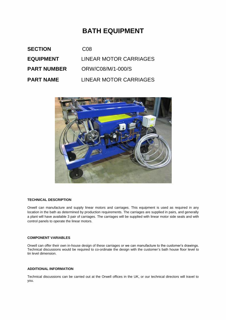
PART NAME LINEAR MOTOR CARRIAGES
TECHNICAL DESCRIPTION
Orwell can manufacture and supply linear motors and carriages. This equipment is used as required in any
location in the bath as determined by production requirements. The carriages are supplied in pairs, and generally
a plant will have available 3 pair of carriages. The carriages will be supplied with linear motor side seals and with
control panels to operate the linear motors.
COMPONENT VARIABLES
Orwell can offer their own in-house design of these carriages or we can manufacture to the customer’s drawings. Technical discussions would be required to co-ordinate the design with the customer’s bath house floor level to tin level dimension.
ADDITIONAL INFORMATION
Technical discussions can be carried out at the Orwell offices in the UK, or our technical directors will travel to you.

BATH EQUIPMENT
SECTION C08
EQUIPMENT LINEAR MOTOR CARRIAGES
PART NUMBER ORW/C08/M/1-001/S
PART NAME FILTER/REGULATOR/LUBRICATOR
TECHNICAL DESCRIPTION
Mounted on the linear motor carriage pneumatic panel, the filter/regulator/lubricator assembly cleans, controls and lubricates the incoming compressed air into the carriage pneumatic system.
COMPONENT VARIABLES
None.
ADDITIONAL INFORMATION
The filter/regulator/lubricator assembly is not a standard stock spare item held by Orwell, but Orwell can generally have one available within 4 weeks or earlier.

BATH EQUIPMENT
SECTION C08
EQUIPMENT LINEAR MOTOR CARRIAGES
PART NUMBER ORW/C08/M/1-002/S
PART NAME FLOW CONTROL REGULATOR
TECHNICAL DESCRIPTION
The flow control regulator is mounted into the pneumatic panel to control the air flow to the pneumatic cylinder.
COMPONENT VARIABLES
None.
ADDITIONAL INFORMATION
The flow control regulator is not a standard stock spare item held by Orwell, but Orwell can generally have one available within 4 weeks or earlier.

BATH EQUIPMENT
SECTION C08
EQUIPMENT LINEAR MOTOR CARRIAGES
PART NUMBER ORW/C08/M/1-003/S
PART NAME PNEUMATIC CYLINDER
TECHNICAL DESCRIPTION
The pneumatic cylinder operates the carriage emergency raise mechanism which quickly raises the linear motor
clear of the tin in the event of an emergency.
COMPONENT VARIABLES
None.
ADDITIONAL INFORMATION
The pneumatic cylinder is not a standard stock spare item held by Orwell, but Orwell can generally have one available within 6 weeks or earlier.

CO8 Linear Motors
BATH EQUIPMENT
SECTION C08
EQUIPMENT LINEAR MOTORS
PART NUMBER ORW/C08/M/2-001/S
PART NAME 12 POLE LINEAR MOTOR
TECHNICAL DESCRIPTION
Linear motors are used in the bath to help give some control of the temperature profile across the ribbon width.
This is achieved by controlling tin flows within the bath, the motors operate on the principle of generating a
magnetic field which as tin is a conductor will cause a pulling or pushing effect on the surface of the tin thus
creating flows within the tin. The linear motors for general bath use are mounted on carriages and are generally
operated in pairs either side of the bath. Orwell can supply 12 pole linear motors which we source from a long
established linear motor manufacturer (R. Baker Electrical). All motors are fully tested prior to despatch.
COMPONENT VARIABLES
These are standard components.
ADDITIONAL INFORMATION
Technical discussions can be carried out at the Orwell offices in the UK, or our technical directors will travel to you.
BATH EQUIPMENT
SECTION C08
EQUIPMENT LINEAR MOTORS
PART NUMBER ORW/C08/M/2-002/S
PART NAME 6 POLE LINEAR MOTOR
TECHNICAL DESCRIPTION
Linear motors are used in the bath to help give some control of the temperature profile across the ribbon width.
This is achieved by controlling tin flows within the bath, the motors operate on the principle of generating a
magnetic field which as tin is a conductor will cause a pulling or pushing effect on the surface of the tin thus
creating flows within the tin. The linear motors for general bath use are mounted on carriages and are generally
operated in pairs either side of the bath. Orwell can supply 6 pole linear motors which we source from a long
established linear motor manufacturer (R. Baker Electrical). All motors are fully tested prior to despatch.
COMPONENT VARIABLES
These are standard components.
ADDITIONAL INFORMATION
Technical discussions can be carried out at the Orwell offices in the UK, or our technical directors will travel to you.

BATH EQUIPMENT
SECTION C08
EQUIPMENT LINEAR MOTORS
PART NUMBER ORW/C08/M/2-003/S
PART NAME 6 POLE DE DROSSING LINEAR MOTOR
TECHNICAL DESCRIPTION
Linear motors can also be used in the de drossing pockets of the bath to help maintain clean tin in the bath by
removing “dross” floating on the tin surface. The linear motor pulls tin from the exit lip area into the de drossing
pocket where the dross is held in the pocket by a weir allowing it to be removed when required. The linear motors
for modern day de drossing pockets are straight 6 pole motors which sit on the pocket refractory sides and are
supported by a simple stand from the bath floor. Orwell can supply de drossing linear motors which we source
from a long established linear motor manufacturer (R. Baker Electrical). All motors are fully tested prior to
despatch.
COMPONENT VARIABLES
These are standard components.
ADDITIONAL INFORMATION
As these motors are not mounted on a linear motor carriage a separate stand alone flow alarm control panel and transformer are initially supplied with these de drossing linear motors along with a support stand.

BATH EQUIPMENT
SECTION C08
EQUIPMENT LINEAR MOTORS
PART NUMBER ORW/C08/M/2-004/S
PART NAME 6 POLE DE DROSSING LINEAR MOTOR
‘T’ SHAPED DESIGN
TECHNICAL DESCRIPTION
Linear motors can also be used in the de drossing pockets of the bath to help maintain clean tin in the bath by
removing “dross” floating on the tin surface. The linear motor pulls tin from the exit lip area into the de drossing
pocket where the dross is held in the pocket by a weir allowing it to be removed when required. The linear motors
for older de drossing pockets are ‘T’ shaped 6 pole motors which sit on the pocket refractory sides and are
supported by a simple stand from the bath floor. Orwell can supply de drossing linear motors which we source
from a long established linear motor manufacturer (R. Baker Electrical). All motors are fully tested prior to
despatch.
COMPONENT VARIABLES
These are standard components.
ADDITIONAL INFORMATION

C15 Coating Equipment

BATH EQUIPMENT
SECTION C15
EQUIPMENT COATING EQUIPMENT
PART NUMBER ORW/C15/M/1-000/V
PART NAME COATING EQUIPMENT
TECHNICAL DESCRIPTION
Orwell can manufacture and supply a coater beams, coater carriages, steelwork, side seals, ancillary
components and control panels to customers manufacturing drawings.
COMPONENT VARIABLES
There may be variants on coating equipment, technical discussions will be necessary and a full set of manufacturing drawings from the customer.
ADDITIONAL INFORMATION
Technical discussions if required can be carried out at the Orwell offices in the UK, or our technical directors will travel to you.
.

C21 Complete Electrical
& Mechanical Top Roll
Machine Package

BATH EQUIPMENT
SECTION C21
EQUIPMENT TOP ROLL MACHINES
PART NUMBER ORW/C21/M/1-000/V
PART NAME TOP ROLL MACHINES
COMPLETE TOP ROLL MACHINES
WITH CONTROL PANELS
TECHNICAL DESCRIPTION
Orwell can manufacture top roll machines including machine wiring and control panels to customer’s design
drawings. The package will include full functional testing of the machines with the control panels in our
workshops at inspection. Alternatively Orwell can offer their own in-house design of top roll machines and control
panels.
COMPONENT VARIABLES
There are many variants of top roll machines. Technical discussions would therefore be necessary to agree the machine specification.
ADDITIONAL INFORMATION
Technical discussions can be carried out at the Orwell offices in the UK, or our technical directors will travel to you. Orwell can if so required by the customer just manufacture and wire the machines and exclude the control panel from the scope of supply.
BATH EQUIPMENT
SECTION C21
EQUIPMENT TOP ROLL MACHINES
PART NUMBER ORW/C21/M/1-001/V
PART NAME BARREL/KNURL ASSEMBLY
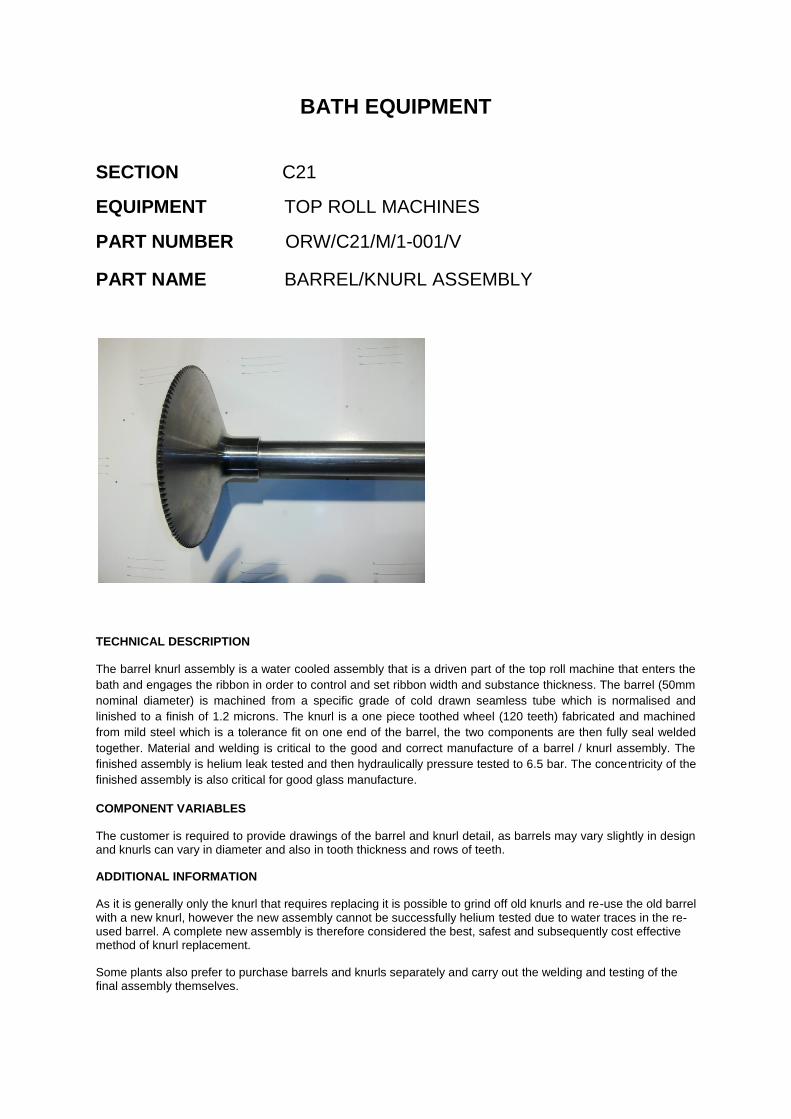
TECHNICAL DESCRIPTION
The barrel knurl assembly is a water cooled assembly that is a driven part of the top roll machine that enters the
bath and engages the ribbon in order to control and set ribbon width and substance thickness. The barrel (50mm
nominal diameter) is machined from a specific grade of cold drawn seamless tube which is normalised and
linished to a finish of 1.2 microns. The knurl is a one piece toothed wheel (120 teeth) fabricated and machined
from mild steel which is a tolerance fit on one end of the barrel, the two components are then fully seal welded
together. Material and welding is critical to the good and correct manufacture of a barrel / knurl assembly. The
finished assembly is helium leak tested and then hydraulically pressure tested to 6.5 bar. The concentricity of the
finished assembly is also critical for good glass manufacture.
COMPONENT VARIABLES
The customer is required to provide drawings of the barrel and knurl detail, as barrels may vary slightly in design and knurls can vary in diameter and also in tooth thickness and rows of teeth.
ADDITIONAL INFORMATION
As it is generally only the knurl that requires replacing it is possible to grind off old knurls and re-use the old barrel with a new knurl, however the new assembly cannot be successfully helium tested due to water traces in the re-used barrel. A complete new assembly is therefore considered the best, safest and subsequently cost effective method of knurl replacement.
Some plants also prefer to purchase barrels and knurls separately and carry out the welding and testing of the final assembly themselves.

BATH EQUIPMENT
SECTION C21
EQUIPMENT TOP ROLL MACHINES
PART NUMBER ORW/C21/M/1-002/V
PART NAME BARREL
TECHNICAL DESCRIPTION
The barrel is a water cooled tube onto which the knurl head is welded to, the barrel provides a return
chamber for cooling water that is used to cool the knurl. The assembled unit when fitted onto the top
roll machine and operated engages the glass ribbon in the bath and controls and sets ribbon width
and substance. The barrel is machined from a specific grade of cold drawn seamless tube which is
normalised and linished to a finish of 1.2 microns and has a strict eccentricity tolerance.
COMPONENT VARIABLES
The customer is required to provide a detail drawing of the barrel, as barrels may vary slightly in design.
ADDITIONAL INFORMATION
None

BATH EQUIPMENT
SECTION C21
EQUIPMENT TOP ROLL MACHINES
PART NUMBER ORW/C21/M/1-003/V
PART NAME KNURL
TECHNICAL DESCRIPTION
The knurl is a one piece toothed wheel (120 teeth) fabricated and machined from mild steel to
become a tolerance fit onto the top roll barrel prior to being fully welded to the barrel. The knurl is the
component on the top roll machine that is “nipped” onto the glass ribbon to control the ribbon width
and substance thickness. Knurls are manufactured to a strict concentricity tolerance. Each knurl when
supplied as an individual unit is helium leak tested.
COMPONENT VARIABLES
The customer is required to provide a detail drawing of the knurl, as knurls may vary slightly in diameter,
tooth thickness and rows of teeth.
ADDITIONAL INFORMATION
None

BATH EQUIPMENT
SECTION C21
EQUIPMENT TOP ROLL MACHINES
PART NUMBER ORW/C21/M/1-004/V
PART NAME QUILL
TECHNICAL DESCRIPTION
The quill is a length of heat resisting steel tube grade 321S20 which provides a passageway of water
supply from the top roll machine rotary union to the knurl head. One end of the quill locates into the
knurl head whilst the other end has a ½” BSP thread to enable it to screw into the rotary union.
COMPONENT VARIABLES
The customer is required to provide a detail drawing of the quill, as quills may vary slightly in design.
ADDITIONAL INFORMATION
None
BATH EQUIPMENT
SECTION C21
EQUIPMENT TOP ROLL MACHINES
PART NUMBER ORW/C21/M/1-005/V
PART NAME WATER COOLED BARREL HOUSING
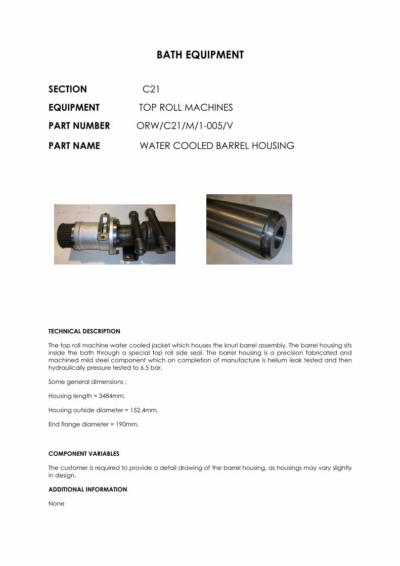
TECHNICAL DESCRIPTION
The top roll machine water cooled jacket which houses the knurl barrel assembly. The barrel housing sits
inside the bath through a special top roll side seal. The barrel housing is a precision fabricated and
machined mild steel component which on completion of manufacture is helium leak tested and then
hydraulically pressure tested to 6.5 bar.
Some general dimensions :
Housing length = 3484mm.
Housing outside diameter = 152.4mm.
End flange diameter = 190mm.
COMPONENT VARIABLES
The customer is required to provide a detail drawing of the barrel housing, as housings may vary slightly
in design.
ADDITIONAL INFORMATION
None

BATH EQUIPMENT
SECTION C21
EQUIPMENT TOP ROLL MACHINES
PART NUMBER ORW/C21/M/1-006/S
PART NAME BARREL HOUSING GRAPHITE BUSH
TECHNICAL DESCRIPTION
A hard wearing machined graphite bush that is a tolerance fit into the end boss of the barrel housing.
The bore of the bush is a toleranced diameter to provide a running fit to allow the top roll barrel to
rotate in the bore. The bush is held secure by a modified M6 capscrew screwed through the end boss
of the barrel housing and locating into a 5mm wide slot in the bush.
Material – Graphite grade CY9.
Bush outside diameter = 70.018/69.988mm with 1mm x 45° chamfer on all outer edges.
Bush inside diameter = 50.500/50.539mm with 3mm x 45° chamfer on slotted end.
Overall length = 65mm.
One 5mm wide slot x 12mm long in one end (radiussed).
COMPONENT VARIABLES
This is a standard component.
ADDITIONAL INFORMATION
None
BATH EQUIPMENT
SECTION C21
EQUIPMENT TOP ROLL MACHINES
PART NUMBER ORW/C21/M/1-007/S
PART NAME FLOW INDICATOR
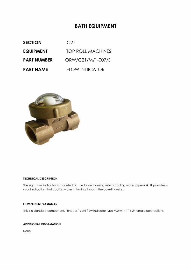
TECHNICAL DESCRIPTION
The sight flow indicator is mounted on the barrel housing return cooling water pipework. It provides a
visual indication that cooling water is flowing through the barrel housing.
COMPONENT VARIABLES
This is a standard component. “Rhodes” sight flow indicator type 400 with 1” BSP female connections.
ADDITIONAL INFORMATION
None
BATH EQUIPMENT
SECTION C21
EQUIPMENT TOP ROLL MACHINES
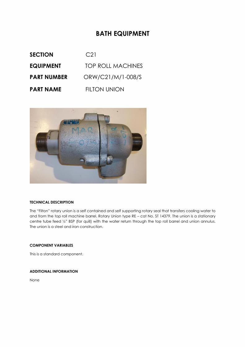
PART NUMBER ORW/C21/M/1-008/S
PART NAME FILTON UNION
TECHNICAL DESCRIPTION
The “Filton” rotary union is a self contained and self supporting rotary seal that transfers cooling water to
and from the top roll machine barrel. Rotary Union type RE – cat No. ST 14379. The union is a stationary
centre tube feed ½” BSP (for quill) with the water return through the top roll barrel and union annulus.
The union is a steel and iron construction.
COMPONENT VARIABLES
This is a standard component.
ADDITIONAL INFORMATION
None
BATH EQUIPMENT
SECTION C21
EQUIPMENT TOP ROLL MACHINES
PART NUMBER ORW/C21/M/1-009/V
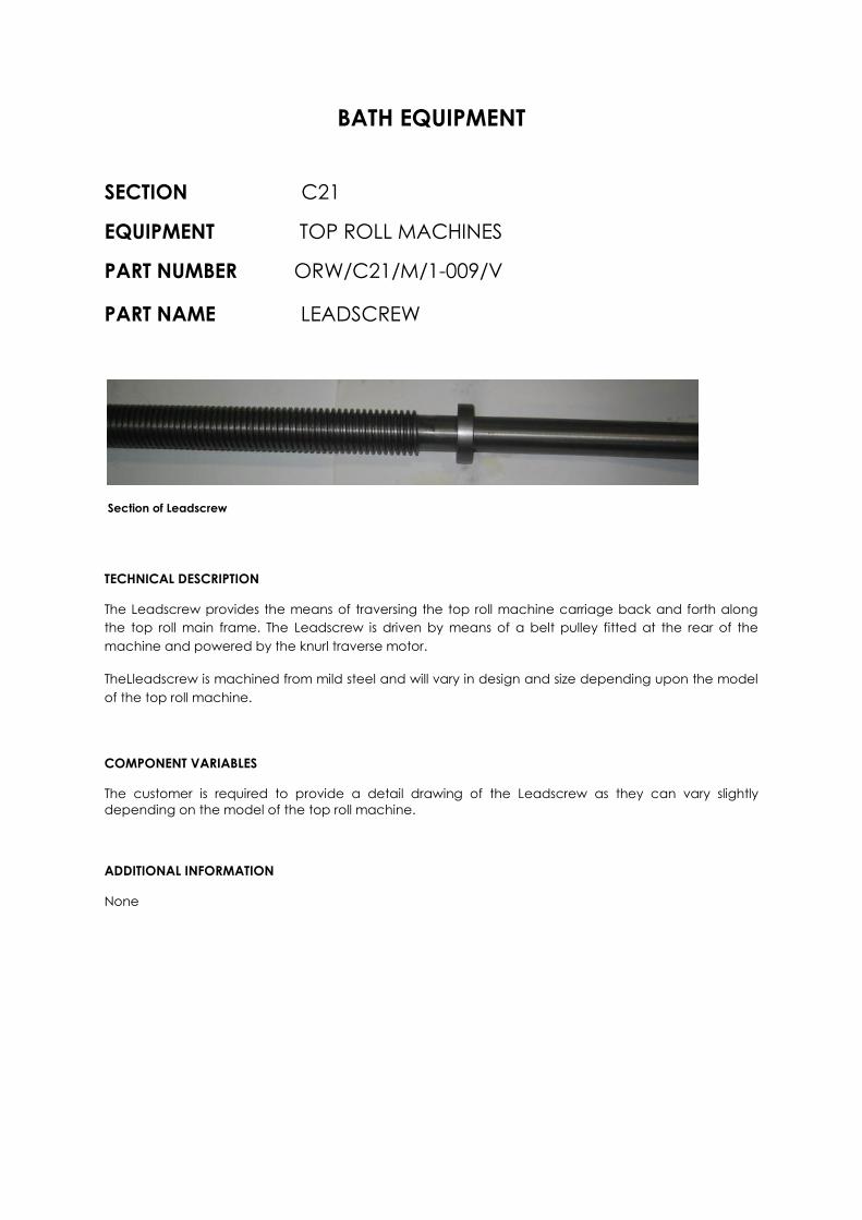
PART NAME LEADSCREW
Section of Leadscrew
TECHNICAL DESCRIPTION
The Leadscrew provides the means of traversing the top roll machine carriage back and forth along
the top roll main frame. The Leadscrew is driven by means of a belt pulley fitted at the rear of the
machine and powered by the knurl traverse motor.
TheLleadscrew is machined from mild steel and will vary in design and size depending upon the model
of the top roll machine.
COMPONENT VARIABLES
The customer is required to provide a detail drawing of the Leadscrew as they can vary slightly
depending on the model of the top roll machine.
ADDITIONAL INFORMATION
None

BATH EQUIPMENT
SECTION C21
EQUIPMENT TOP ROLL MACHINES
PART NUMBER ORW/C21/M/1-010/V
PART NAME LEADSCREW NUT
TECHNICAL DESCRIPTION
The Leadscrew Nut facilitates the drive connection between the top roll machine carriage and the
Leadscrew drive on the main frame.
The Nut is a split type design manufactured from phosphor bronze and its size will vary depending upon
the top roll machine model and Leadscrew size.
COMPONENT VARIABLES
The customer is required to provide a detail drawing of the Nut as Leadscrew Nuts can vary slightly in
design.
ADDITIONAL INFORMATION
None
BATH EQUIPMENT
SECTION C21
EQUIPMENT TOP ROLL MACHINES
PART NUMBER ORW/C21/E/1-011/S
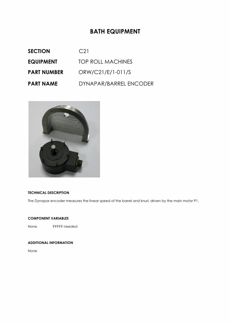
PART NAME DYNAPAR/BARREL ENCODER
TECHNICAL DESCRIPTION
The Dynapar encoder measures the linear speed of the barrel and knurl, driven by the main motor P1.
COMPONENT VARIABLES
None ????? needed
ADDITIONAL INFORMATION
None

BATH EQUIPMENT
SECTION C21
EQUIPMENT TOP ROLL MACHINES
PART NUMBER ORW/C21/E/1-012/V
PART NAME MAIN DRIVE MOTOR / GEARBOX (SERVICE
PACKAGE)
TECHNICAL DESCRIPTION
The Siemans synchronous motor and Opperman gearbox unit for driving the knurl. These units are difficult to
source and are a very long lead and expensive item from new. Orwell can offer a service exchange package
whereby a completely overhauled motor and gearbox can be shipped out to the customer in exchange for the
customer’s old unit.
COMPONENT VARIABLES
The customer is required to provide the full specification of the motor and gearbox to ensure complete compatibility with the overhauled unit being offered.
ADDITIONAL INFORMATION
None

BATH EQUIPMENT
SECTION C21
EQUIPMENT TOP ROLL MACHINES
PART NUMBER ORW/C21/E/1-013/V
PART NAME LIMIT SWITCHES
Type 1LS1-4C
TECHNICAL DESCRIPTION
There are two types of “Honeywell” limit switches used on the top roll machines Honeywell type 1LS1-4C (used
on the machine handwheels) illustrated above, and Honeywell type BZE9-2RQ8-PG a special limit switch (used
on the nip). Both of these limit switches are available as a stock spare from Orwell.
COMPONENT VARIABLES
The customer is required to identify the function of the limit switch required.
ADDITIONAL INFORMATION
None
BATH EQUIPMENT
SECTION C21
EQUIPMENT TOP ROLL MACHINES
PART NUMBER ORW/C21/M/1-014/S
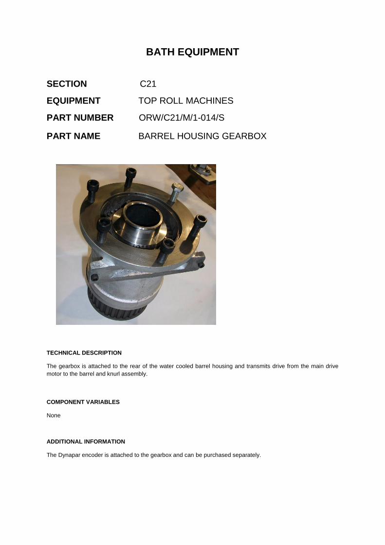
PART NAME BARREL HOUSING GEARBOX
TECHNICAL DESCRIPTION
The gearbox is attached to the rear of the water cooled barrel housing and transmits drive from the main drive
motor to the barrel and knurl assembly.
COMPONENT VARIABLES
None
ADDITIONAL INFORMATION
The Dynapar encoder is attached to the gearbox and can be purchased separately.

BATH EQUIPMENT
SECTION C21
EQUIPMENT TOP ROLL MACHINES
PART NUMBER ORW/C21/M/1-015/S
PART NAME TOP ROLL MACHINE HANDWHEEL SPRING
TECHNICAL DESCRIPTION
The Top Roll Handwheel Spring keeps the handwheel disengaged from the clutch drive when the leadscrew is
driven under power.
COMPONENT VARIABLES
None
ADDITIONAL INFORMATION
None.

BATH EQUIPMENT
SECTION C21
EQUIPMENT TOP ROLL MACHINES
PART NUMBER ORW/C21/M/1-016/S
PART NAME LEAD SCREW SPRING
TECHNICAL DESCRIPTION
The Lead Screw Spring is located at each end of the Lead Screw to prevent the main carriage disengaging from
the Lead Screw.
COMPONENT VARIABLES
None
ADDITIONAL INFORMATION
None.

BATH EQUIPMENT
SECTION C21
EQUIPMENT TOP ROLL MACHINES
PART NUMBER ORW/C21/M/1-017/S
PART NAME FILTER/REGULATOR/LUBRICATOR
TECHNICAL DESCRIPTION
Mounted in the top roll machine pneumatic control box the filter/regulator/lubricator unit cleans, controls and
lubricates the compressed air supply to the pneumatic system.
COMPONENT VARIABLES
None
ADDITIONAL INFORMATION
The filter/regulator/lubricator assembly is not a standard stock spare item held by Orwell, but Orwell can generally have one available within 4 weeks or earlier.

BATH EQUIPMENT
SECTION C21
EQUIPMENT TOP ROLL MACHINES
PART NUMBER ORW/C21/M/1-018/S
PART NAME AIR MOTOR
TECHNICAL DESCRIPTION
The air motor operates the nip raise/ nip lower drive to the knurl head.
The motor is a “Gast” 8 vane reversible motor reference 1UP-NRV-11-GR11 and comes with ⅛” NPT air
connection ports.
COMPONENT VARIABLES
None.
ADDITIONAL INFORMATION
The air motor is not a standard stock spare item held by Orwell, but Orwell can generally have one available within 6 weeks or earlier.

BATH EQUIPMENT
SECTION C21
EQUIPMENT TOP ROLL MACHINES
PART NUMBER ORW/C21/M/1-019/S
PART NAME PNEUMATIC CYLINDER
TECHNICAL DESCRIPTION
The pneumatic cylinder operates the emergency nip raise for the knurl head.
The cylinder is a “Compair Maxam” cylinder reference P1D-S100MS-50 and comes with a rear clevis mounting
bracket reference P1C4QMT.
COMPONENT VARIABLES
None.
ADDITIONAL INFORMATION
Replacement cylinders can just be provided without the clevis mounting bracket. The cylinders are not a standard stock spare item held by Orwell, but Orwell can generally have one available within 4 weeks or earlier.

BATH EQUIPMENT
SECTION C21
EQUIPMENT TOP ROLL MACHINES
PART NUMBER ORW/C21/M/1-020/S
PART NAME SCREW JACK
TECHNICAL DESCRIPTION
The screw jack operates the knurl raise/lower mechanism on the top roll machine.
The screw jack is a “Power Jacks” jack reference 1802 upright jack with a 75mm stroke and 14:1 gearing ratio
and comes with a clevis screw end connection.
COMPONENT VARIABLES
ADDITIONAL INFORMATION
The screw jack is not a standard stock spare item held by Orwell, but Orwell can generally have one available within 8 weeks or earlier.

BATH EQUIPMENT
SECTION C21
EQUIPMENT TOP ROLL MACHINES
PART NUMBER ORW/C21/M/1-021/S
PART NAME SPIDER COUPLING
TECHNICAL DESCRIPTION
The spider coupling forms the mechanical connection between the screw jack and the nip adjust hand wheel
shaft on the top roll machine.
The spider coupling is a “Renold” spider coupling with the bore machined to suit the keyway on the nip adjust
shaft..
COMPONENT VARIABLES
None.
ADDITIONAL INFORMATION
The spider coupling is not a standard stock spare item held by Orwell, but Orwell can generally have one available within 5 weeks or earlier.

BATH EQUIPMENT
SECTION C21
EQUIPMENT TOP ROLL MACHINES
PART NUMBER ORW/C21/M/1-022/V
PART NAME BEVEL GEARS
TECHNICAL DESCRIPTION
The bevel gears form the mechanical drive connections between the air motor and the screw jack and manual
override shaft, and they are also used to form the manual connection between the leadscrew and the front hand
wheel shaft.
All the bevel gears have the same gearing and tooth profile but the bore of the bevel gears differ depending upon
which particular bevel gear is required.
COMPONENT VARIABLES
The bore details of the bevel gear varies depending upon its location on the top roll machine, the customer should identify which particular bevel gear is required.
ADDITIONAL INFORMATION
The bevel gears should not require replacing during a glassmaking campaign unless they have been damaged by external forces. At a cold repair the gear teeth should be inspected for excess wear and damage and replaced as necessary.
The gears are not a standard stock spare item held by Orwell, but Orwell can generally have one available within 4 weeks or earlier.
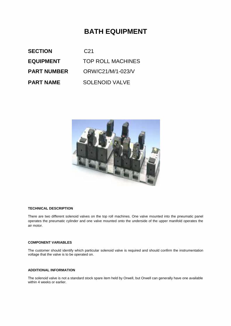
BATH EQUIPMENT
SECTION C21
EQUIPMENT TOP ROLL MACHINES
PART NUMBER ORW/C21/M/1-023/V
PART NAME SOLENOID VALVE
TECHNICAL DESCRIPTION
There are two different solenoid valves on the top roll machines. One valve mounted into the pneumatic panel
operates the pneumatic cylinder and one valve mounted onto the underside of the upper manifold operates the
air motor.
COMPONENT VARIABLES
The customer should identify which particular solenoid valve is required and should confirm the instrumentation voltage that the valve is to be operated on.
ADDITIONAL INFORMATION
The solenoid valve is not a standard stock spare item held by Orwell, but Orwell can generally have one available within 4 weeks or earlier.

BATH EQUIPMENT
SECTION C21
EQUIPMENT TOP ROLL MACHINES
PART NUMBER ORW/C21/M/1-024/V
PART NAME FLOW CONTROL VALVE
TECHNICAL DESCRIPTION
There are four flow control valves on the top roll machines of two different sizes. There are two flow control
valves mounted into the pneumatic panel which control the air flow to the pneumatic cylinder and there are two
flow control valves assembled to the solenoid control valve for the air motor.
COMPONENT VARIABLES
The customer should identify which particular flow control valve is required when ordering. The flow control valves for the pneumatic cylinder are reference S837 (½” port size) and the flow control valves for the air motor are reference M839 (¼” port size).
ADDITIONAL INFORMATION
The flow control valve is not a standard stock spare item held by Orwell, but Orwell can generally have one available within 4 weeks or earlier.

BATH EQUIPMENT
SECTION C21
EQUIPMENT TOP ROLL MACHINES
PART NUMBER ORW/C21/M/1-025/S
PART NAME CHECK UNIT & ADAPTOR
TECHNICAL DESCRIPTION
The check units and adaptors facilitate the connection and quick release of the top roll machine to the
compressed air pipeline at the bath side. The female check unit part is screwed to the compressed air stub pipe
connection at the bath side whilst the adaptor is fitted to the flexible compressed air hose attached to the top roll
machine. Together the two parts allow for a quick and safe installation / removal of the machine to the main
compressed air supply.
COMPONENT VARIABLES
None
ADDITIONAL INFORMATION
The check units are not a standard stock spare item held by Orwell, but Orwell can generally have one available within 4 weeks or earlier. These items are also used on Motorised Positioner Units and Linear Motor Carriages.

C21 Top Roll
Side Seals
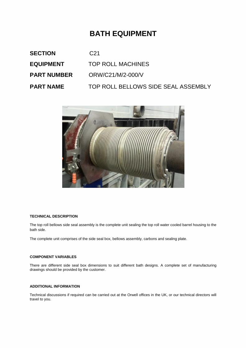
BATH EQUIPMENT
SECTION C21
EQUIPMENT TOP ROLL MACHINES
PART NUMBER ORW/C21/M/2-000/V
PART NAME TOP ROLL BELLOWS SIDE SEAL ASSEMBLY
TECHNICAL DESCRIPTION
The top roll bellows side seal assembly is the complete unit sealing the top roll water cooled barrel housing to the
bath side.
The complete unit comprises of the side seal box, bellows assembly, carbons and sealing plate.
COMPONENT VARIABLES
There are different side seal box dimensions to suit different bath designs. A complete set of manufacturing drawings should be provided by the customer.
ADDITIONAL INFORMATION
Technical discussions if required can be carried out at the Orwell offices in the UK, or our technical directors will travel to you.

BATH EQUIPMENT
SECTION C21
EQUIPMENT TOP ROLL MACHINES
PART NUMBER ORW/C21/M/2-001/S
PART NAME SIDE SEAL BELLOWS
TECHNICAL DESCRIPTION
The Top Roll Bellows facilitates a flexible sealed connection between the top roll machine barrel
housing and the top roll side seal, whilst allowing the top roll machine to be capable of travelling
through the full range of its slew parameters. The Bellows is manufactured from stainless steel grade
S527 or EN58B.
Standard bellows sizes -
Bellows type ‘A’
Overall length = 381mm.
Outside diameter over convolutions = 272.5.
Inside diameter at cuffs = 238mm.
Number of convolutions = 54 (reference).
Length over convolutions = 343 (reference).
Material thickness = 0.0075/0.0085 inches (0.1905/0.2159mm).
COMPONENT VARIABLES
The customer is required to provide a drawing of the Bellows to ensure compatibility with the top roll
machine.
ADDITIONAL INFORMATION
Due to the environment in which they operate the Bellows will over time become brittle and splits may
occur, this will cause oxygen ingress into the bath. The Bellows should be replaced when damaged to
avoid glassmaking problems.

BATH EQUIPMENT
SECTION C21
EQUIPMENT TOP ROLL MACHINES
PART NUMBER ORW/C21/M/2-002/S
PART NAME SIDE SEAL BELLOWS GRAPHITE BUSH
TECHNICAL DESCRIPTION
There are four (4) Graphite Bearings fitted into each Top Roll Bellows on assembly with the top roll
machine. The bearings help form a seal around the top roll bearing water cooled bearing housing
body and the bellows.
The bearing is machined from graphite CS grade.
Outside diameter = 172.855mm/172.696mm.
Inside diameter = 152.6mm/152.7mm.
Overall length = 50mm.
2mm x 45° chamfers on all edges.
COMPONENT VARIABLES
This is a standard component.
ADDITIONAL INFORMATION
None.

BATH EQUIPMENT
SECTION C21
EQUIPMENT TOP ROLL MACHINES
PART NUMBER ORW/C21/M/2-003/V
PART NAME TADPOLE SEAL
TECHNICAL DESCRIPTION
The tadpole seal is used to form an air tight seal between the top roll side seal front plate and the
bellows adaptor mounting plate. The tadpole seal is attached by a series of screws through its tail to
the front plate of the top roll side seal section.
Seal specification :-
Fibreglass cloth with wire mesh bulb.
Bulb diameter = 25mm.
Seal tail length = 25mm.
COMPONENT VARIABLES
This is a standard component for the top roll machine side seals.
ADDITIONAL INFORMATION
This material is used on other items of equipment but the bulb diameter and tail length may be
different, customer to specify if ordering for other equipment.

C35
Bath Periscopes

BATH EQUIPMENT
SECTION C35
EQUIPMENT BATH PERISCOPES
PART NUMBER ORW/C35/M/1-000/V
PART NAME BATH PERISCOPE SYSTEM
TECHNICAL DESCRIPTION
The complete bath periscope system is available and comprises of all the hanging brackets, carriage, tracks,
water cooled jacket, ‘Introvision’ optical tube, camera and bath roof sealing plug.
COMPONENT VARIABLES
There are water jacket length and camera variations as well as a manual or motorised operation design.
ADDITIONAL INFORMATION
Technical discussions if required can be carried out at the Orwell offices in the UK, or our technical directors will travel to you. Viewing monitors for the control room and if required local to the periscopes at the bath side are not included in the Orwell supply.

BATH EQUIPMENT
SECTION C35
EQUIPMENT BATH PERISCOPES
PART NUMBER ORW/C35/M/1-001/V
PART NAME PERISCOPE TUBE WATER JACKET
TECHNICAL DESCRIPTION
The periscope water jacket provides the housing and cooling protection for the periscope optical tube for insertion
into the bath. The water jacket is a precision fabricated and machined component adhering to strict welding
procedures, which on completion of manufacture is helium leak tested and the hydraulically pressure tested to
6.5 bar.
Material – Water jacket housing – heat resisting steel grade 321S31
Manifold housing – mild steel
Overall length of water jacket = this is a variable dimension depending upon the optical tube length.
Water jacket body outside diameter = 4” (102.6mm)
Manifold housing outside diameter = 152mm
COMPONENT VARIABLES
The customer is required to provide a detail drawing of the water jacket, as jackets do vary slightly in design.
ADDITIONAL INFORMATION
Orwell will trial fit an optical tube in the water jacket housing on completion of manufacture.

BATH EQUIPMENT
SECTION C35
EQUIPMENT BATH PERISCOPES
PART NUMBER ORW/C35/M/1-002/S
PART NAME PERISCOPE BATH SEALING SILICONE SEAL
TECHNICAL DESCRIPTION
This seal is used to seal around the periscope water jacket and the bath roof casing when the
periscope is inserted into the bath.
A moulded cylindrical silicone rubber seal with a carbon bush insert.
Seal diameter = 179mm & 140mm
Bore diameter = 146mm & 102mm
Overall length = 143mm
Carbon bush insert material CS grade or HLM grade graphite.
COMPONENT VARIABLES
This is a standard component.
ADDITIONAL INFORMATION
The physical dimensions of the seal may vary slightly due to shrinkage over a long period of time. This is
normal.
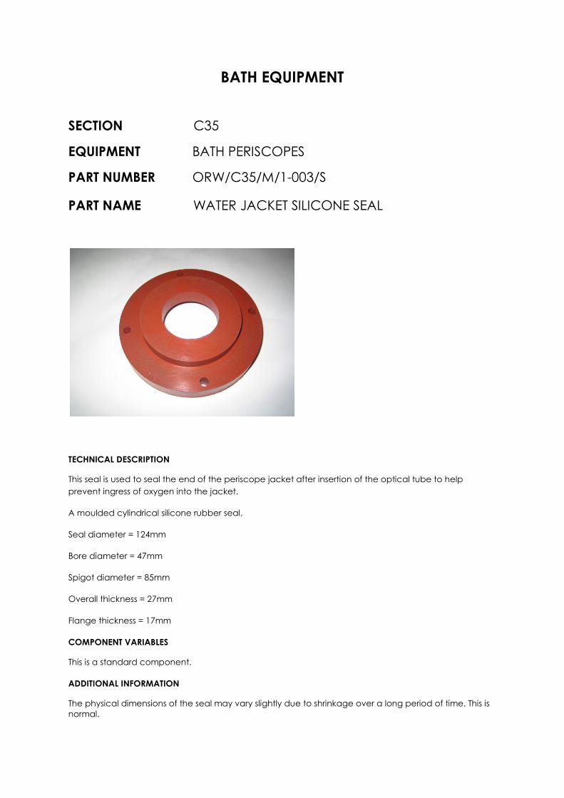
BATH EQUIPMENT
SECTION C35
EQUIPMENT BATH PERISCOPES
PART NUMBER ORW/C35/M/1-003/S
PART NAME WATER JACKET SILICONE SEAL
TECHNICAL DESCRIPTION
This seal is used to seal the end of the periscope jacket after insertion of the optical tube to help
prevent ingress of oxygen into the jacket.
A moulded cylindrical silicone rubber seal.
Seal diameter = 124mm
Bore diameter = 47mm
Spigot diameter = 85mm
Overall thickness = 27mm
Flange thickness = 17mm
COMPONENT VARIABLES
This is a standard component.
ADDITIONAL INFORMATION
The physical dimensions of the seal may vary slightly due to shrinkage over a long period of time. This is
normal.

BATH EQUIPMENT
SECTION C35
EQUIPMENT BATH PERISCOPES
PART NUMBER ORW/C35/M/1-004/S
PART NAME FLOW INDICATOR
TECHNICAL DESCRIPTION
The sight flow indicator is mounted to the top of the periscope carriage on the CCCW return pipework.
It provides a visual indication that cooling water is flowing through the periscope. There is one indicator
on every periscope carriage.
COMPONENT VARIABLES
This is a standard component. “Rhodes” sight flow indicator type 400 with 1” BSP connections.
ADDITIONAL INFORMATION
None

BATH EQUIPMENT
SECTION C35
EQUIPMENT BATH PERISCOPES
PART NUMBER ORW/C35/M/1-005/V
PART NAME OPTICAL TUBE (INTROVISION)
TECHNICAL DESCRIPTION
The periscope optical tube is manufactured from heat resisting steel and optically set up by Introvision Ltd UK. As
the optical tube can have a long delivery period Orwell will hold as a stock item a small quantity of tubes for
immediate delivery, complete with any locating collars, ’C’ mounts and clamping rings that accompany the tube.
COMPONENT VARIABLES
The customer is required to provide the tube length, the camera mounting details and the camera make, type and specification for which the tube is to be used with. The detail drawing of the tube from the periscope drawing package should also be provided by the customer.
ADDITIONAL INFORMATION
None

BATH EQUIPMENT
SECTION C35
EQUIPMENT BATH PERISCOPES
PART NUMBER ORW/C35/M/1-006/S
PART NAME HEAT ABSORBING FILTER GLASS
TECHNICAL DESCRIPTION
A heat absorbing filter glass that fits in a slot at the front of the camera water box to protect the camera lens from
the heat. Filter type HA3
COMPONENT VARIABLES
This is a standard component size 50 x 50 x 3 mm.
ADDITIONAL INFORMATION
These filters are only used on older style periscopes that require a water cooled box for the periscope camera.
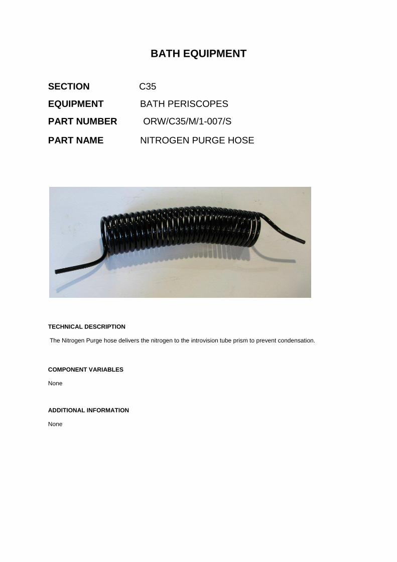
BATH EQUIPMENT
SECTION C35
EQUIPMENT BATH PERISCOPES
PART NUMBER ORW/C35/M/1-007/S
PART NAME NITROGEN PURGE HOSE
TECHNICAL DESCRIPTION
The Nitrogen Purge hose delivers the nitrogen to the introvision tube prism to prevent condensation.
COMPONENT VARIABLES
None
ADDITIONAL INFORMATION
None

C35 Bath Optical
Substance Gauge

BATH EQUIPMENT
SECTION C35
EQUIPMENT OPTICAL SUBSTANCE GAUGE
PART NUMBER ORW/C35/M/2-000/V
PART NAME OPTICAL SUBSTANCE GAUGE
TECHNICAL DESCRIPTION
Orwell can manufacture and supply a complete bath optical substance gauge including the instrumentation box to
the customers design drawings and specifications.
COMPONENT VARIABLES
There may be variants on the substance gauge design (particularly the electronics box). Technical discussions will be necessary and a full set of manufacturing drawings from the customer.
ADDITIONAL INFORMATION
Technical discussions if required can be carried out at the Orwell offices in the UK, or our technical directors will travel to you.
Orwell only manufacture and supply the substance gauge, all setting up and programming of the equipment is the customer’s responsibility.

BATH EQUIPMENT
SECTION C35
EQUIPMENT BATH SUBSTANCE GAUGE
PART NUMBER ORW/C35/M/2-001/S
PART NAME RECEIVER (EMITTER) TUBE
TECHNICAL DESCRIPTION
The substance gauge tubes provide a water cooled housing that is inserted into the bath in order to measure the
glass thickness. The water jacket is a precision fabricated and machined component adhering to strict welding
procedures, which is helium leak tested at various stages of manufacture and on completion is helium tested and
then hydraulically pressure tested to 6.5 bar.
Material – Receiver (emitter) tubes – heat resisting steel 321 S31.
Manifold housing – mild steel.
Overall length = 2078mm.
Water jacket body outside diameter = 4¼ inches (107.95mm).
Manifold housing outside diameter (largest diameter) = 152mm.
COMPONENT VARIABLES
This is a standard component, however the tubes are handed, should the customer only require one of the tubes
they must specify whether it is the receiver or emitter tube. In such cases the detail drawing will be required to
avoid misinterpretation.
ADDITIONAL INFORMATION
None

BATH EQUIPMENT
SECTION C35
EQUIPMENT BATH SUBSTANCE GAUGE
PART NUMBER ORW/C35/M/2-002/S
PART NAME SUBSTANCE GAUGE BATH SEALING
SILICONE SEAL
TECHNICAL DESCRIPTION
This seal is used to seal around the substance gauge receiver and emitter water jackets and the aperture in the
bath side seal when the substance gauge is inserted into the bath.
A moulded tapered cylindrical silicone rubber seal.
Seal diameter = 176mm & 130mm
Bore diameter = 158mm & 112mm
Overall length = 160mm
COMPONENT VARIABLES
This is a standard component.
ADDITIONAL INFORMATION
The physical dimensions of the seal may vary slightly due to shrinkage over a long period of time. This is normal.
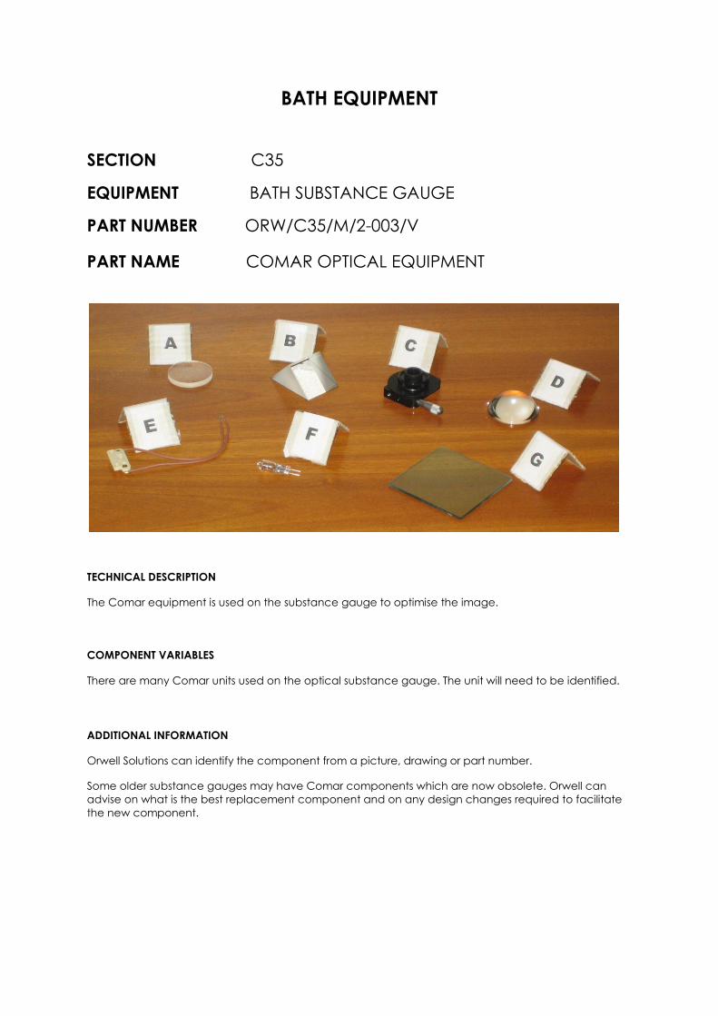
BATH EQUIPMENT
SECTION C35
EQUIPMENT BATH SUBSTANCE GAUGE
PART NUMBER ORW/C35/M/2-003/V
PART NAME COMAR OPTICAL EQUIPMENT
TECHNICAL DESCRIPTION
The Comar equipment is used on the substance gauge to optimise the image.
COMPONENT VARIABLES
There are many Comar units used on the optical substance gauge. The unit will need to be identified.
ADDITIONAL INFORMATION
Orwell Solutions can identify the component from a picture, drawing or part number.
Some older substance gauges may have Comar components which are now obsolete. Orwell can
advise on what is the best replacement component and on any design changes required to facilitate
the new component.

C35 Bath Camera
Systems

BATH EQUIPMENT
SECTION C35
EQUIPMENT BATH TV CAMERA SYSTEM
PART NUMBER ORW/C35/M/4-000/V
PART NAME BATH CAMERA BOXES
TECHNICAL DESCRIPTION
The system comprises of cameras housed in water cooled boxes supported on a simple steel structure mounted
to the outside of the bath roof casing. The cameras view the inside of the bath through an atmosphere cooled
window. The cameras are generally located at the hot end of the bath, the shoulder section of the bath and
between the dross box and lehr (both sides of the bath).
The boxes are fabricated from mild steel plate to suit the camera to be used and the finished camera box water
chamber is pressure tested to 4.5 bar.
The internal surfaces of the camera box are painted heat resisting matt black and the outside is painted silver.
COMPONENT VARIABLES
There are many differing camera box designs and sizes depending upon the location to be used in the bath and on the camera to be used.
ADDITIONAL INFORMATION
If required Orwell can also supply the camera for the box to the customer’s specification.

BATH EQUIPMENT
SECTION C35
EQUIPMENT BATH TV CAMERA BOXES
PART NUMBER ORW/C35/M/4-001/S
PART NAME TOUGHENED FLOAT GLASS FILTER
TECHNICAL DESCRIPTION
A piece of toughed float glass fitted into the slot at the front of the Bath TV Camera water jacket to protect the
camera lens from the heat. This is fitted to the hot end and shoulder bath camera boxes.
COMPONENT VARIABLES
This is a standard component size 80 x 80 x 6mm.
ADDITIONAL INFORMATION

Spares Order
& Quotation Request

UNLISTED ITEMS
Fax/email request
If the item you require is not listed in this catalogue, please complete this form
and fax/email it to Orwell Engineering Solutions. Orwell will supply the item
and add it to the catalogue so you can purchase it in the future from stock.
From: ……………………………………………………………………………………
Company:………………………………………………………………………………
Address:…………………………………………………………………………….……
………………………………………………………………………..……………………
……………………………………………………………………………………………..
Contact tel: ……………………………………………………………………………...
Product request
Item name: ………………………………………………………………………….
Drawing Number: …………………………………………………………………….
Description/specification of item:
…………………………………………………………………………………………………
…………………………………………………………………………………………………
…………………………………………………………………………………………………
…………………………………………………………………………………………………
…………………………………..
Please fax this form to Mr Chris Smith, Orwell Engineering Solutions Ltd
Fax: +44 (0) 151 525 3288
Or alternatively email your request to [email protected]

SPARES ORDER / QUOTATION REQUEST FORM
Fax / email request
From: .......................................................................................................................
Company: .......................................................................................................................
Address: ........................................................................................................................
........................................................................................................................
........................................................................................................................
Contact tel: ........................................................................................................................
I would like (a quotation for / to order) the following item(s):-
PART NUMBER PART NAME QUANTITY REQUIRED
ORW/..............................
ORW/..............................
ORW/..............................
ORW/..............................
ORW/..............................
Delivery method required (i.e. ex works UK or delivery to above address or other)
.............................................................................................................................................
Drawing(s) attached with this request (if applicable) - YES NO
Drawing Numbers - ..............................................................................................................
Additional comments –
..............................................................................................................................................
..............................................................................................................................................
..............................................................................................................................................
...............................................................................................................................................
Please fax this form to Mr Chris Smith, Orwell Engineering Solutions Ltd
Fax:- ++ 44 (0) 151 525 3288
Or alternatively email your request to [email protected]

www.orwell-engineering.co.uk
Orwell Engineering Solutions,
1 Farriers Way,
Liverpool, L30 4XL
United Kingdom
Telephone: 00 44 (0)151 530 2000
Email: [email protected]
Fax: 00 44 (0)151 525 3288
4
“Intelligent Engineering Solutions”