battery and charge controller basics, testing and
TRANSCRIPT

BATTERY AND CHARGE
CONTROLLER BASICS, TESTING AND
CHARACTERISATION
NCPRE, IIT Bombay
28 Nov 2104 Brajesh Kumar Sinha

Fourth Partner Energy – Our Vision • Our objective is to be a Partner for sustainable change
– solar is our focus.
• We aim to enhance the quality of human life while conserving our planet.
• We endeavor to do so by providing innovative products and services that harness the renewable resources, and provide our customers with superior quality at lower costs.
• Our ‘Fourth Partner’ is ‘YOU’. – Our customer, our supplier, our employee or any
stakeholder.
2

Fourth Partner Energy – Background • Started in 2010 with a focus on OFF grid solar energy
market in emerging countries. • We have a strong product design and manufacturing
presence (products like lanterns, street lights, charge controllers, home lighting systems). Our operating team has over 10 years of experience.
• We specialize in design and installation of rooftop solar solutions for corporate and industrial clients
• We are developing our brand , as solar power packs transition to a B-2-C retail play.
• For solar thermal applications, we have invested significantly in basic CSP development and technology.
• We have executed a 66 kV Power Evacuation system on a turnkey basis, for a 5MW grid connected power plant near Rajkot, Gujarat.
3

Our Clients

TOPICS
Battery concepts
Types of batteries: Lead Acid, NiCd, and Li-ion batteries
Battery basic terminology
Battery Charging
Characteristics of solar battery
Lead Acid, NiCd, and Li-ion batteries comparative analysis
Battery Testing
Applicable Standards
Charge Controller Testing

WHAT IS A CELL OR BATTERY? Cell is a device that stores and
converts the chemical energy into electrical energy by means of an electrochemical reaction.
Battery consists of two or more
cells electrically connected.
In common usage, the terms "battery" and "cell" are used interchangeably.

CELL CONNECTIONS
Series connection: When opposite polarity of
two or more cells are connected to each other and overall voltage is taken out, the total voltage becomes the sum of each cell voltage and the totalcapacity remains the same as of a single cell.
2V 200AH
2V 200AH
4V, 200 Ah
Parallel connection:
When similar polarities of two or more cells are connected and overall voltage is taken out from the cell(s) in the battery, the total voltage remains same as of a single cell but the total capacity becomes the sum of the capacity of all cells.
2V 200AH
2V 200AH
2V, 400 Ah

TYPES OF BATTERY
Battery
Primary Secondary
Use & Throw Rechargeable
Lead Acid Nickel Cadmium Lithium Ion Ni-MH etc

Features Lead Acid Ni Cd Li - Ion
Nominal Voltage
2.00 1.20 3.60
Design Life
(Approx in Yrs)
10-20 10-20 10
Battery Management
Optional Optional Compulsory
Storage 06 months 01 Year – charged 10 year – uncharged
01 year
Cost Low High Very High
TYPES OF BATTERIES Contd….

Battery Capacity: Amount of energy stored in the battery. Depends on … 1. Quantity of active materials 2. Amount of electrolyte 3. Surface area of the plates
Rated capacity: Amount of charge available in ampere-hours (Ah) when battery discharged at specified rate.
I t is indicated on battery datasheet by ‘C’ rate.
• Battery capacity varies with the discharge rate.
Example:
Lead-acid battery rated for 200 Ah (10-hour rate) will deliver 20 amperes of current for 10 hours under standard temperature conditions before its terminal voltage reaches specified value.
BASIC TERMINOLOGY

Charge & Discharge: Charge current is the electric current supplied to the battery and stored in it. Energy supplied to battery will be “charge current x time period x battery voltage”. Discharge is the state when battery energy is being consumed by the connected load. Energy removed from battery will be “load current x time period x battery voltage” State of Charge: the “state of charge” is a measure of energy remaining in the battery. I t can be measured with the help of following. • Multimeter – 2.12V (100%), 2.01V (50%), 1.75V (0%) • Hydrometer – 1220, 1160, 1120 (20%), NA
BASIC TERMINOLOGY contd….

Cycle: Each charge period followed by its discharged period is called a cycle. Cycle life: The number of cycles a battery is expected to last before its capacity drops to 80% is called cycle life. I t depends on how deeply the battery is discharged. Lesser the DoD higher the cycle life.
Depth of Discharge (DoD): I t is a measure of how much battery is discharged in a cycle before it is charged again. 60% DoD is equivalent to 40% state of charge (SoC). PSoC: The battery is not being fully charged (100%) before they are discharged in a cycle.
BASIC TERMINOLOGY contd….

Freshening Charge: For extending storage period
Float Charge: Compensation for self discharge
Charger, battery, and load are connected in parallel
Boost Charge: Fast charging at higher voltage when battery discharges to higher depth
Equalization Charge: Equalize the cell voltage in Battery bank to avoid over/under charge of cells
TYPES OF BATTERY CHARGING

• Smallest size and weight - High Energy Density
• High cycle and float life
• Low self Discharge & Good Shelf life
• PSoC operation
• Charge Efficiency at PSoC
• Deep Discharge recovery
• Resistance to abuse
• Predictable performance
CHARACTERISTICS OF SOLAR BATTERY

CHARACTERISTICS OF SOLAR BATTERY
• Quick installation and commissioning
• Wide operating temperature and
mechanical stress
• Low or no maintenance requirements Topping free
• Environment friendly
• Low cost


TYPES OF LEAD-ACID BATTERIES
Gel VRLA
Lead Acid Battery
Flat Plate Tubular Positive Plate
AGM VRLA Flooded Flooded

Flooded Lead-Acid Batteries Electrodes/plates are immersed in electrolyte Vented for gas escape Distilled water must be added periodically Sealed Lead-Acid Batteries No free electrolyte Oxygen recombination Regulated vent to allow gases to escape at threshold pressure - 2 to 5 psi, depending on the battery design
Features of Flooded & VRLA LA Batteries

LA BATTERY PARTS
• +ve Electrode: PbO2
• -ve Electrode: Pb
• Electrolyte : H2 SO4
• Container: Polypropylene/Hard Rubber
• Separator: AGM (Absorbent Glass Mat)


DIFFERENT TYPES OF LA PLATES
Plante Flat grid Tubular

Plate/Electrode • Active material – Stores the charge • Grid - Electrical conductor & support for active material Different types of plates Plante plate: Active material has been electro-
chemically produced over lead sheet
Flat pasted plate : Active material has been supported by lead alloy mesh
Tubular plate : The paste is held in micro-porous,
non-conductive tubes (gauntlets)
DIFFERENT TYPES OF LA PLATES

CHEMICAL REACTIONS IN LEAD-ACID CELLS
1. At the Negative Electrode: Discharge Pb + H2SO4 PbSO4 + 2H+ + 2e-
Charge E0 = 0. 356 V 2. At the Positive Electrode: Discharge PbO2 + 2H+ + H2SO4 + 2e- PbSO4 + 2H2O Charge E0 = 1. 685 V 3. Overall Reaction: Discharge PbO2 + Pb + 2H2SO4 PbSO4 + PbSO4 + 2H2O Charge E0 = 2. 041 V

PERFORMANCE COMPARISON OF LA BATTERIES
Performance requirement Tubular LMLA Flat plate (AGM) Tubular gel
Maintenance (water top-up)
Maintenance Un-avoidable
Maintenance free (No top-up reqd)
Maintenance free No top-up reqd)
Stratification High Low Nil
Cycle life Good Moderate Excellent
Deep discharge recovery Good Moderate Excellent
Partial state of charge operation
Excellent Good Excellent
Capacity at C120, C240 Excellent Good Excellent
Self discharge characteristic
Moderate Excellent Excellent
Low temperature operations
Moderate Excellent Good
High temperature operations
Excellent Moderate Excellent
Ease of installation Initial charging required
Ready to use Ready to use

NICKEL CADMIUM BATTERIES
Designed to perfection, Built to last

NI CD BATTERY PARTS
• +ve Electrode: Nickel Hydroxide Ni(OH)2
• -ve Electrode: Cadmium Hydroxide Cd(OH)2
• Electrolyte : Potassium Hydroxide (KOH)
• Container : Polypropylene
• Separator : Micro porous PVC

NiCd Characteristics
Nominal Voltage : 1.2 Volts
Float Voltage : 1.40 – 1.42 Volts
Boost Voltage : 1.53 - 1.70 Volts
Electrolyte : KOH of Specific gravity 1.20 ± 0.01
Operating temperature : - 500C to + 500C

A. 2 Ni (OH)2 + 2 OH- 2 NiOOH + 2 H2O + 2 e- V+= 0.49V B. Cd (OH)2 + 2 e- Cd + 2 OH-
V- = 0.809V
Over all reaction of a Nickel Cadmium Battery is as follows C. 2 Ni (OH)2 + Cd (OH)2 2 NiOOH + Cd + 2 H2O
Potential difference of Ni-Cd cell shall be Vo = 0.490 – (-0.809)
= 1.299
* Electrolyte does not take part in reaction; it is only a carrier of ions
Charge
Discharge
NI CD ELECTROCHEMI STRY
Charge
Discharge
Charge
Discharge

LI THI UM I ON BATTERY

SALI ENT FEATURES - LI BATTERI ES
High Energy Density Lithium Ion energy density is approximately 3 to 5 times of a Lead Acid.
High Voltage The maximum output operating voltage of our lithium-ion battery is 3.7v per cell that exceeds three times higher than that of Ni-Mh, Ni-Cd battery (1.2V per cell).
High Rate Discharge Lithium Ion Batteries offers approximately 45% more discharge capacity than Lead Acid at 2C discharge rate.
Fast Charge Fast charging is possible with a charger exclusive for the lithium ion battery (1CmA, 4.2V CC-CV).
No Memory Effect Lithium ion batteries have no memory effect.
Long Cycle Life Lithium ion batteries last over 5000 repeated charges and discharges.
Minimal Self-Discharge Lithium Ion retains approximately 29% more capacity retained by Lead Acid in 1 year at 25’C and approximately 50% more capacity in 10 years.
High Storage Characteristics The residual capacity after 3 month storage is over 95%.

LI THI UM I ON CHEMI STRI ES
Cathode Materials
• Lithium metal oxides
• Li CoO2
• LiMn2O4
• Li FePO4
• ….. etc
Anode Materials
• Lithium metal
• Active Carbons
• Graphite
• Tin Oxides
• Others

HOW DOES A LI THI UM I ON CELL WORK?
• During the Charge Process • At the Cathode: • LixCoO2 Li(1-x)CoO2 + xLi+ + xe –
• At the anode: • xLi+ + xe– + LixC6 LiC6
Overall Cell Reaction: LixCoO2 + C6 LiC6 + Li(1-x)CoO2 E = 3.0 ~3.6 V
• During the Discharge Process • At the Cathode: • Li(1-x)CoO2 + xLi+ + xe – LiCoO2
• At the anode: • LiC6 xLi+ + xe– + LixC6

A LI THI UM I ON CELL

CHARGE & DI SCHARGE VOLTAGE CHARACTERI STI CS
2.7
2.9
3.0
3.2
3.3
3.5
3.6
3.8
3.9
4.1
4.2
0 400 800 1200 1600 2000 2400
Cell Discharge Capacity(mAh)
Cel
l Vol
tage
(V)
4.0V Charge4.1V Charge4.2V Charge
Model : ICR18650-22 ( 1CmA = 2200mA)Charge : CC-CV 0.5C-4.0V/4.1V/4.2V, 3Hr or 20mA cut-offDischarge : CC 0.2C, 2.75 V cut-off at 25℃

HI GH RATE DI SCHARGE CHARACTERI STI CS
2.7
2.9
3.0
3.2
3.3
3.5
3.6
3.8
3.9
4.1
4.2
0 400 800 1200 1600 2000 2400
Cell Discharge Capacity(mAh)
Cel
l Vol
tage
(V)
Charge: CC-CV 0.5C/4.2V, 3Hr or 20mA cut-off (1CmA=2200mA)
0.2C / 0.5C / 1.0C / 1.5C / 2.0C / 3.0C Discharge

COMPARATI VE ANALYSI S
Parameter VRLA Tubular GEL Lithium poly Charging efficiency High Lower High
Space requirement Large cell size, Huge space requirement
Large cell size, Huge space requirement
Smallest Size
Stacking Horizontal or vertical Up to 1500 AH : Horizontal or vertical
>1500 AH: Vertically, in tiers
Horizontal is preferable ,Vertical is possible.
Self-discharge during storage, at an average temperature of 35°C.
50% self-discharge in 6 months. Recovery easy.
50% self-discharge in one year. Recovery easy.
< 2~3% / month (Retention >80% at 1year)
Cyclic Life
(to 80% DoD).
1400 cycles at an average temperature of 35°C in normal environmental condition
Better than 2100 cycles at an average temperature of 35°C in normal environmental condition
> 5,000 cycles at 25’C(1C charge/discharge)

Charging Requirement
Constant voltage charging by SMPS Power plants
Constant voltage charging by SMPS Power plants
CC-CV mode charge.
Lower current (<1C) is better for cycle-life
Thermal runaway Probable, yet rare Not possible No thermal runaway
Even at the abuse test
Self-discharge during storage, at an average temperature of 35°C.
50% self-discharge in 6 months. Recovery easy.
50% self-discharge in one year. Recovery easy.
< 2~3% / month (Retention >80% at 1year)
Cyclic Life
(to 80% DoD).
1400 cycles at an average temperature of 35°C in normal environmental condition
Better than 2100 cycles at an average temperature of 35°C in normal environmental condition
> 5,000 cycles at 25’C(1C charge/discharge)
COMPARATI VE ANALYSI S
Parameter VRLA Tubular GEL Lithium poly

Parameter VRLA Tubular GEL Lithium Poly High temperature performance
Average, with temperature compensation
Good Good, Same or higher capacity than that of 25’C
Low temperature performance
Good Good Good, 80% at -10’C (1C)(Cycle-life degradation can happen )
Stratification Negligible, no boost charging required.
Negligible, no boost charging required.
No limit (<1,000V)
End cell voltage 1.75V/cell 1.75V/cell 2.0V Minimum
COMPARATI VE ANALYSI S
Deep discharge recovery
Average, after 4 to 5 charge/discharge cycles
Average, after 4 to 5 charge/discharge cycles
Recovery >95% is possible within 1~2cycle
Charge efficiency Excellent, 6 to 8 hours for 90% recovery
Slightly poor, 8 to 10hrs for 90% recovery
Excellent,
Overcharging
Performance
Poor, damages the battery.
Good In a cell-level, 2C 10V overcharge can be guaranteed.

BATTERY TESTING
Battery Testing Visual Inspection/Verification of dimension
Leakage Test
Specific Gravity Checking – 1240
SG27/(1+0.00007*(T-27))
Acceptance/Capacity Test at 10 hr rate
Storage Test
Endurance Test
Ah & Wh Efficiency Test

BATTERY TYPE TEST & ACCEPTANCE TEST
Battery Type Test Verification of constructions requirements
Verification of marking
Verification of dimension
Test of Capacity
Ampere-hour and Watt-hour capacity
Test of loss of capacity on storage
Endurance Test
Battery Acceptance Test Verification of marking
Verification of dimension
Test of Capacity

VERIFICATION OF DIMENSION
Verification of dimension Equipment Used: Need to check calibration date
Digimatic Caliper
Height Gauge
Steel Rule
Thermometer
Test Conditions: Temperature = 25 deg C
Test Procedure:
To check length, width and height of the batteries with Steel Rule, Digimatic Caliper, and Height Gauge
Requirements:
Overall dimensions of the batteries shall not exceed the values given in the standard

VERIFICATION OF DIMENSION
Test Result:
Description Dimensions
specified in the standard
Values observed
Length (mm) 525 511
Width (mm) 295 211.27
Height (mm) 300 266.67
Result PASS

VISUAL INSPECTION: CONSTRUCTIONAL REQUIREMENTS
Constructional Requirements and Marking Test Procedure:
Various components of battery viz. Battery Lids, Electrolyte Level indicator, Terminal post, connections, terminal connections, nuts & bolts, are examined visually.
Requirements:
All components/parameters of the battery shall comply with the specific requirements given in the IS standards.

Test Result: Visual Inspection
Description Specific Requirements Observations RESULT
Battery Lids Battery lid shall be provided in each cell
Battery lid made up of Hard rubber shall be of
deep sealing type
Battery lid made up of plastic shall be of deep
sealing type or glued type
Battery lid provided in each cell
Battery are made up of
plastic hence not applicable
Battery lid are made up of plastic and are of deep
sealing type
PASS
---
PASS
Electrolyte Level Indicator
Each cell shall have electrolyte level indicator for indicating lower and
upper limits of electrolyte
Each cell is fitted with vent plug cum float guide
PASS
Terminal Post Positive and Negative post shall be clearly
identifiable
Positive and Negative post are clearly identifiable
PASS
VISUAL INSPECTION: CONSTRUCTIONAL REQUIREMENTS

Test Result: Marking
Description Observation RESULT
Source of Manufacturer
HBL Power Systems Limited (marked on self-adhesive sticker)
PASS
Ah Capacity at C10 Rate
12V 80Ah (marked on self-adhesive sticker)
PASS
Upper and Lower electrolyte level in case of transparent container
Batteries are made of opaque plastic container hence not applicable
--
Year of Manufacture 11-2014 (Nov 14 punched on terminal posts)
PASS
Country of Origin INDIA PASS
Each cell and battery may also be marked with standard (ISI) mark – Optional
Battery are not marled with ISI mark --
VISUAL INSPECTION: CONSTRUCTIONAL REQUIREMENTS

LEAKAGE TEST
Equipment Used: Water tank, compressed air Test Procedure:
Cell is dipped into the water tank and air pressure is applied upto 10-11 psi.
Requirements:
Leakage is not permitted
Test Result:
If any leak path is there in the cell, air inside the cell comes out through the leak path which can be observed in the form of air bubble coming out from the cell.

CAPACITY TEST AT 10 hr RATE
Equipment Used: Life Cycle Tester, Clamp Meter, Multimeter, Thermometer, Hydrometer.
Test Procedure:
Fully charged battery is discharged at C10 rate (8.0A for 80Ah battery) until on-load voltage of battery reaches 10.8V; recharge at 8.0A until voltage reaches 2.4V/cell (14.4V), charge further at 4.0A until voltage reaches 2.600 to 2.700V/cell (15.6V to 16.2V); rest for 12 hr.
Requirements:
Actual capacity obtained shall not be less than 100% of rated 10 hr capacity.

Test Result:
Description Battery 1 Battery 2
Open circuit voltage (V) 12.74 12.74
Electrolyte Specific Gravity
1.245 1.240
Obtained Capacity 86.4 87.1
Result PASS PASS
CAPACITY TEST AT 10 Hr RATE
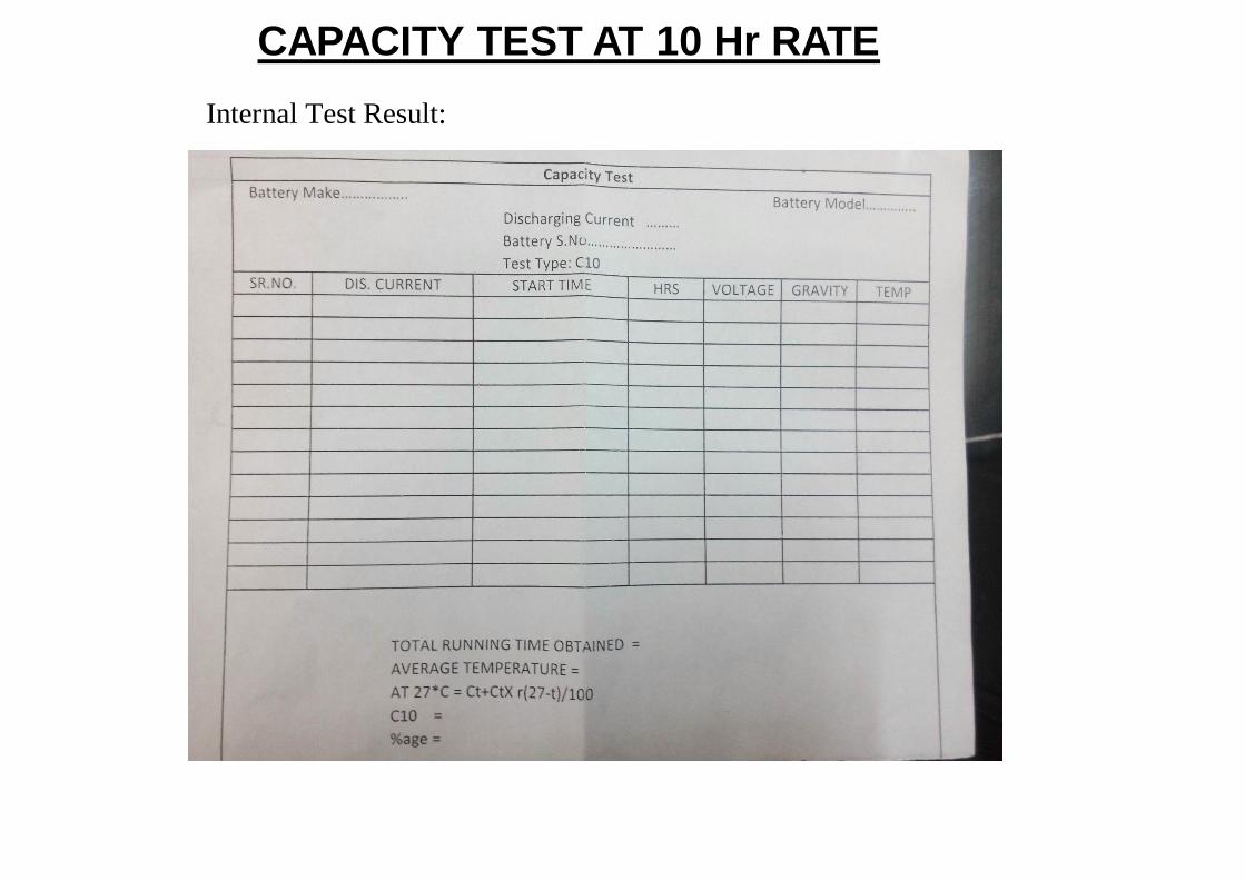
Internal Test Result:
CAPACITY TEST AT 10 Hr RATE

AMPERE-HOUR AND WATT-HOUR EFFICIENCY TEST
Equipment Used: Life Cycle Tester, Clamp Meter, Multimeter, Thermometer, Hydrometer.
Test Procedure:
Fully charged battery is discharged at C10 rate (8.0A for 80Ah battery) until on-load voltage of battery reaches 10.8V – 1st
Discharge; recharge the battery at 8.0A until it receive an input equal to the capacity obtained in 1st discharge; Rest for 12 Hour; dischargethe battery @ 8.0 A until on-load voltage reaches 10.80V – 2nd
discharge
Requirements:
Ampere- hour efficiency and Watt-hour efficiency shall not be less than 90% and 75% respectively.

Test Result:
Description Battery 1 Battery 2
Open circuit voltage (V) 12.59 12.56
Electrolyte Specific Gravity
1.240 1.235
Ampere-hour efficiency (%)
95.5 94.4
Watt-hour efficiency (%) 83.8 81.8
RESULT PASS PASS
AMPERE-HOUR AND WATT-HOUR EFFICIENCY TEST

ENDURANCE TEST
Equipment Used: Life Cycle Tester, Hot water bath (upto 70 deg C), Clamp Meter, Multimeter, Thermometer, Hydrometer
Test Procedure:
Fully charged battery is placed in hot water bath maintained at the temperature of 40±3 deg C; The battery is overcharged @8.0A for 2000 hrs; Sequence of 2000 hrs over charge – 2 cycles of 300 hrs charging followed by discharge at 10 hr rate, 3 cycles of 200 hrs charging followed by discharge at 10 hr rate; 8 cycles of 100 hrs charging followed by discharge at 10 hr rate.
Requirements:
Battery shall give minimum of 9 hour back-up in the final discharge.

Test Result:
1. Discharge @ 10 hr rate; 40 deg C after 2 cycles of 300 hour over charge
Description Battery sl. No.
Open circuit voltage (V) 12.55
Electrolyte Specific gravity 1.235
Discharge duration (Hr: min) 11.58
Avg. Electrolyte temp during discharge 42.2
RESULT PASS
ENDURANCE TEST

Test Result:
2. Discharge @ 10 hr rate; 40 deg C after 3 cycles of 200 hour over charge
Description Battery sl. No.
Open circuit voltage (V) 12.71
Electrolyte Specific gravity 1.240
Discharge duration (Hr: min) 11.38
Avg. Electrolyte temp during discharge 41.4
RESULT PASS
ENDURANCE TEST

Test Result:
3. Discharge @ 10 hr rate; 40 deg C after 8 cycles of 100 hour over charge
Description Battery sl. No.
Open circuit voltage (V) 12.68
Electrolyte Specific gravity 1.240
Discharge duration (Hr: min) 11.02
Avg. Electrolyte temp during discharge 41.4
RESULT PASS
ENDURANCE TEST

LOSS OF CAPACITY ON STORAGE
Equipment Used: Life Cycle Tester, Clamp Meter, Multimeter, Thermometer, Hydrometer
Test Procedure:
Fully charged battery is discharged at C10 rate (8.0A for 80Ah battery) until on-load voltage of battery reaches 10.8V; recharge the battery at 8.0A until voltage reaches 14.4V; further charge continued @4.0A until voltage reaches 15.6 – 16.2V – capacity test at 10hr rate (cycle-1), Capacity test @10hr rate repeated for 2nd time (Cycle-2);After full recharge battery kept under storage in open circuit condition @27±5 deg C for 28 days; after completion of storage without giving any charge battery is tested for capacity @10 hr rate to 10.8V/battery.
Requirements:
Loss of capacity shall not exceed 10%
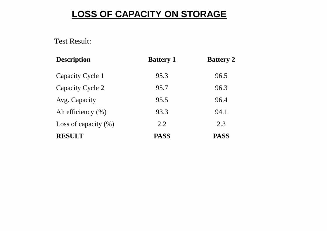
Test Result:
Description Battery 1 Battery 2
Capacity Cycle 1 95.3 96.5
Capacity Cycle 2 95.7 96.3
Avg. Capacity 95.5 96.4
Ah efficiency (%) 93.3 94.1
Loss of capacity (%) 2.2 2.3
RESULT PASS PASS
LOSS OF CAPACITY ON STORAGE

CHARGE CONTROLLER
• Charges battery from a DC Source
• Prevents battery overcharge
• Blocks reverse current
• Prevent over-discharge from batteries
• Prevent electrical overload
• Uncontrolled/Controlled
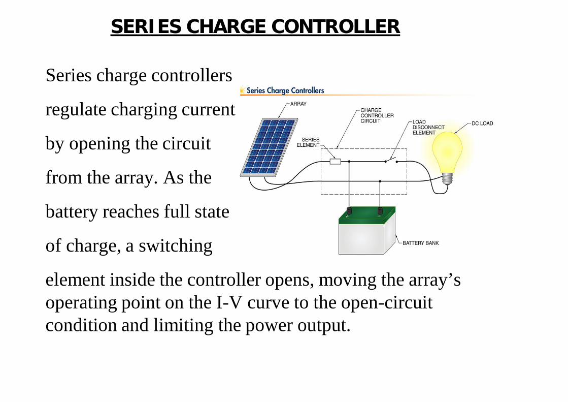
SERIES CHARGE CONTROLLER
Series charge controllers
regulate charging current
by opening the circuit
from the array. As the
battery reaches full state
of charge, a switching
element inside the controller opens, moving the array’s operating point on the I-V curve to the open-circuit condition and limiting the power output.

SHUNT CHARGE CONTROLLER
Shunt charge controllers
regulate charging current
by short-circuiting the array.
Unlike batteries, PV devices
are current-limited by nature,
so PV modules and arrays can
be short-circuited without any harm. A shunt charge controller is a charge controller that limits charging current to a battery system by short-circuiting the array. The array is short-circuited through a shunt element inside the charge controller, moving the array’s operating point on the I-V curve very near the short-circuit condition and limiting the power output. All shunt controllers must also include a blocking diode in series between the battery and the shunt element to prevent the battery from short-circuiting.

PWM CHARGE CONTROLLER
Pulse-width modulation (PWM) simulates a lower current level by pulsing a higher current level ON and OFF for short intervals.
• Battery is charged using pulses of energy that can vary in length and speed according to battery condition.
• As the battery reaches capacity, the flow of energy is slowly tapered off as opposed to sudden cut off to reduce battery overcharging
• Ideal for situations where excess
energy is often present
• Higher charging efficiency
• Rapid recharging
• Healthy battery at full capacity

MPPT CHARGE CONTROLLER
Maximum power point tracking manipulates the load or output voltage of an array in order to maintain operation at or near the maximum power point under changing temperature and irradiance conditions
• A MPPT controller adjusts the voltage output to take advantage of the Vpp and charge the battery more
• Peak Power Voltage (Vpp) is the maximum power point that a PV system can deliver; varies with temperature and sunlight intensity
• The power is transformed by a DC-DC converter circuit into another voltage and current required by the load/ battery.

MPPT CHARGE CONTROLLER
Conventional controller
charges a discharged
Battery by simply
connecting the modules
directly to the battery.
This forces the modules
to operate at battery
voltage12V. The MPPT
system operates the
modules at 17V to
extract the full 75W, regardless of present battery voltage. A high efficiency DC-to-DC power converter converts the 17V module voltage at the controller input to battery voltage at the output.

CHARGE CONTROLLER TESTING
Functional Testing Visual Inspection
Self Consumption
Internal Voltage Drop
Voltage regulation Thresholds
Protections
Maximum current Resistance
DC-DC conversion Efficiency

CHARGE CONTROLLER TESTING
IEC 60068-2 (1,2 14,30)
Test Equipment Used
Programmable Environmental Chamber Votsch/VC³ 4100 Consumption
Environmental Test Chamber KEW/PEC-HYG

DRY HEAT TEST
Dry Heat Test
Pre-checks: Physical damages
Test Specifications:
Test temperature: +55ºC
One cycle Duration: 16 hrs
No. of cycles: one
Pot Checks: No physical damages observed

COLD TEST
Cold Test
Pre-checks: Physical damages
Test Specifications:
Test temperature: -10ºC
One cycle Duration: 02 hrs
No. of cycles: one
Pot Checks: No physical damages observed

DAMP HEAT CYCLE
Damp Heat Cycle
Pre-checks: Physical damages
Test Specifications:
Ramp up /down time: 3 Hrs
One cycle Duration: 12+12 hrs
No. of cycles: Three
Total Test Duration: 72 Hrs
Post Checks: No physical damages observed

CHANGE OF TEMPERATURE
Change of temperature
Pre-checks: Physical damages
Test Specifications:
Test Temperature: Upper +55ºC, Lower -5ºC
Rate of change of temperature: 1ºC/min
Dwell time: 1hr at each temperature
No. of cycles: 5 cycles
Post Checks: No physical damages observed

CHARGE CONTROLLER SETTI NG
• Float Charging Voltage : 2.25 V/cell
• Boost Charging Voltage : 2.35 V/cell
• Charging Current Limit : 10 – 20% of BB Ah
• L.V.D. : 1.90 V/Cell
• H.V.D.: 2.40 V/Cell
• Temp. Compensation: 3 mV/ cell/ per degree celcius
• Ripple Contents: < 3%

APPLI CABLE STANDARDS
Battery standards:
• IS 1651
• IS 13369
• IEC 61427
• IS 15549
Solar Charge Controller Standards
• IEC 60068-2 (1,2,14,30) – Environmental Testing