battery management systembattery · pdf filefeatures features and and and...
TRANSCRIPT

Smart Start BATTERY MANAGEMENT SYSTEMBATTERY MANAGEMENT SYSTEMBATTERY MANAGEMENT SYSTEMBATTERY MANAGEMENT SYSTEM
BMS1215
®

Warnings Warnings Warnings Warnings and and and and Safety InstructionsSafety InstructionsSafety InstructionsSafety Instructions
This manual contains important information relating to the safe installation and operation of the Smart Start® BMS. Please read and understand these instructions before attempting to install or use the Smart Start® BMS.
WARNING Throughout this manual, warnings like this will appear to identify conditions or practices that could result in harm to the user and/or damage to the Smart Start® BMS or other equipment.
IMPORTANT Throughout this manual, important information that the user should know will be denoted like this.
This appliance is not intended for use by persons (including children) with reduced
physical, sensory or mental capabilities, or lack of experience and knowledge, unless
they are supervised or have been instructed how to use the appliance by a person
responsible for their safety. Children should be supervised to ensure that they do not
play with the appliance.
Do NOT disassemble the Smart Start® BMS - the internal circuitry contains hazardous voltages. Attempting to service the unit yourself may result in electric
shock or fire and will void the unit warranty.
Do NOT use the Smart Start® BMS to charge non-rechargeable batteries. Doing so
may result in harm to the user and/or damage to the Smart Start® BMS. Only use
the Smart Start® BMS for charging Standard Lead Acid, Calcium content, Gel & AGM
type 12V batteries.
�

Features Features Features Features and and and and BenefitsBenefitsBenefitsBenefits
1. The Smart Start® BMS incorporates five products in one, negating the need for separate AC 240V charger, solar regulator, DC-DC charge system, battery monitor and vehicle battery isolator. The Smart Start® BMS will automatically select between charging sources, requiring no input from the operator during its operation.
2. The Smart Start® BMS has no fan, which makes it SUPER quiet and very reliable.
3. The Smart Start® BMS is designed and manufactured in Australia, for Australian
conditions, using the latest electronic and design technologies. It is manufactured with high-quality components to ISO9001 quality and ISO14001 environmental standards and backed with Redarc’s quality service and two-year warranty.
4. The Smart Start® BMS’s DC-DC charging enables optimal charging of house
batteries, even if they have different chemical characteristics from the vehicle battery. The input voltage can be above, equal to or below the output voltage.
5. State of Charge (SOC) indication means you will always know how fully charged the
battery is and how much longer it will need to achieve full charge. An easy to operate, high-quality, user friendly liquid crystal display (LCD) module lets you know what’s going on at all times.
6. The Smart Start® BMS is very reliable and includes in-built non-sparking battery
connection, reverse polarity protection (without depending on fuses) and short circuit protection. The unit has undergone stringent safety & electrical compliance testing.
7. The units easily selectable charging profiles make it suitable for charging all battery
types commonly used in modern caravans and motorhomes.
8. The unit disconnects automatically from the vehicle battery, so there is always power to start the car.
9. Sophisticated fault detection monitors the house battery condition during all stages
of charge, keeping you and your caravan/ camper/ RV safe.
10. The Smart Start® BMS has a separate battery temperature sensor for automatic temperature compensation and cut-out.

Table of ContentsTable of ContentsTable of ContentsTable of Contents
Warnings and Safety Instructions Features and Benefits
1 Introduction
1. General Description 2. The Remote Monitor 3. The Kit Includes 4. Specifications 5. Multi-stage Charging Process
2 INSTALLATION Guide
1. System Layout 2. Mounting Instructions
1. Mounting the Main Unit 2. Mounting the Remote Monitor 3. Installing the Current Shunt 4. Installing the Battery Sensor
3. DC Cable Size Requirements 4. Connections 5. Batteries 6. MPPT Solar Regulator
3 USER Guide
1. Remote Monitor 2. Understanding the Display 3. Navigating the Menu 4. Troubleshooting
4 Warranty Conditions

1 Introduction 1.1 General Description
The Smart Start® BMS is designed to offer a complete solution to battery charging and maintenance needs for recreational automotive applications. The Smart Start® BMS incorporates AC, DC and Solar inputs to achieve the best charge to a house battery.
1.2 The Remote Monitor
The Smart Start® BMS comes with a Remote Monitor designed to give you house battery information and charge status along with critical system information while charging is in progress. With the Remote Monitor, you can customise how your house battery is charged and monitor where the charge is coming from, keeping you in control at all times. The Remote Monitor can be surface mounted on a wall, or flush mounted (into the dashboard of an RV for example).
1.3 The Kit Includes
1 Main Unit………………… 2 Remote Monitor……………………………… 3 Current Shunt……………. 4 Temperature Sensor…………………………. 5 Remote Monitor Cable…….. 6 Power Cable………………………………… 7 Shunt Wire………………..

1.4 Specifications
Electrical SpecificationsElectrical SpecificationsElectrical SpecificationsElectrical Specifications
InputsInputsInputsInputs
AC InputAC InputAC InputAC Input
I/P Voltage Range 220 - 240V AC, 50 - 60Hz
Power Rating 280W
Efficiency 92%
Connection Mains Plug
DC InputDC InputDC InputDC Input
I/P Voltage Range 9 - 18V
Power Rating 260W
Efficiency 94%
Connection Terminal Block (See figure 2.4.3)
Solar InputSolar InputSolar InputSolar Input
I/P Voltage Range 9 – 18V
Power Rating 260W
Efficiency 93%
Connection Terminal Block (See figure 2.4.3)
Max Charging Volts @ Battery TerminalsMax Charging Volts @ Battery TerminalsMax Charging Volts @ Battery TerminalsMax Charging Volts @ Battery Terminals
Storage Mode Touring Mode
Gel Setting 14.4V 14.4V
AGM Setting 14.4V 14.4V
Calcium Setting 16.0V 15.2V
Standard Lead Acid Setting 15.5V 14.8V
Float Voltage 13.5V
Output Voltage Ripple <15mV
Output Current (Nominal) 15A
Temperature Compensation -5mV / Batt. Cell / °C
Limit Temperatures 0°C - 75°C (5°C Hysteresis)
Over Temperature Shutdown Yes
Recommended Total Batt Capacity 40 – 400Ah
Required Number of Cells in Series 6 (12V Battery)
Non-Sparking Connection Yes
Memory Save on Battery Disconnect Yes
O/P ProtectionO/P ProtectionO/P ProtectionO/P Protection
Short Circuit Protection Yes
Surge Protection Yes
Reverse Polarity Protection Yes
Overload Protection Yes
ComplianceComplianceComplianceCompliance
C-Tick EMC-CISPR.11
AS/NZS 60335.2.29 Safety
AS/NZS 60335.1
Environmental ROHS Compliant
General SpecificationsGeneral SpecificationsGeneral SpecificationsGeneral Specifications
Main Unit Dimensions 350x185x79mm
Remote Dimensions 186x74x29mm
Kit Weight 2.43 kg
Warranty 2 years

Figure Figure Figure Figure 1111.4.4.4.4.1 .1 .1 .1 –––– Main UnitMain UnitMain UnitMain Unit Dimensions Dimensions Dimensions Dimensions
Figure 1.4Figure 1.4Figure 1.4Figure 1.4.2 .2 .2 .2 –––– Remote Dimensions Remote Dimensions Remote Dimensions Remote Dimensions
All dimensions shown are in millimetres (mm).
1.5 Multi/stage Charging Process
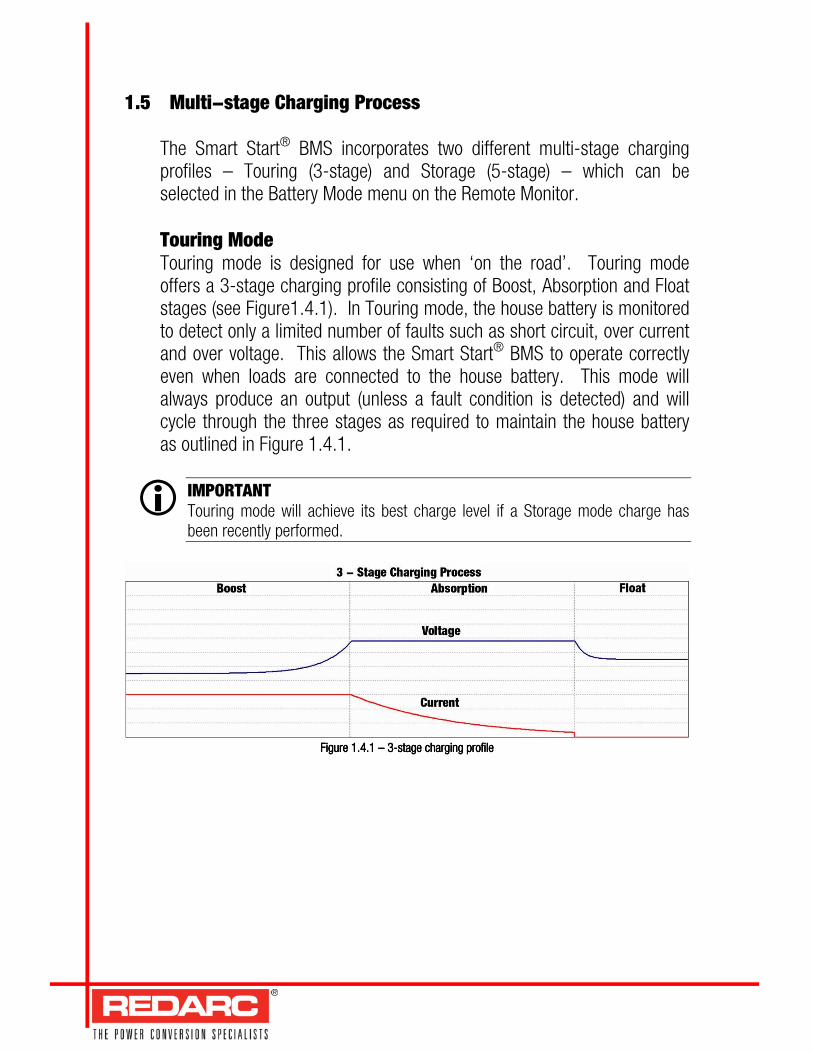
The Smart Start® BMS incorporates two different multi-stage charging profiles – Touring (3-stage) and Storage (5-stage) – which can be selected in the Battery Mode menu on the Remote Monitor. Touring Mode Touring mode is designed for use when ‘on the road’. Touring mode offers a 3-stage charging profile consisting of Boost, Absorption and Float stages (see Figure1.4.1). In Touring mode, the house battery is monitored to detect only a limited number of faults such as short circuit, over current and over voltage. This allows the Smart Start® BMS to operate correctly even when loads are connected to the house battery. This mode will always produce an output (unless a fault condition is detected) and will cycle through the three stages as required to maintain the house battery as outlined in Figure 1.4.1.
IMPORTANT Touring mode will achieve its best charge level if a Storage mode charge has been recently performed.
FigureFigureFigureFigure 1111.4.1.4.1.4.1.4.1 –––– 3 3 3 3----stage cstage cstage cstage charging pharging pharging pharging profilerofilerofilerofile
�

Storage Mode Storage mode is designed to charge the house battery to its optimal level and maintain that level while your caravan is in storage. This mode requires all loads to be switched off or disconnected from the house battery before charging. It uses a 5-stage charging profile consisting of Boost, Absorption, Equalise, Float and Maintenance stages (see Figure1.4.2). Storage mode is designed to detect a wide range of battery fault conditions, for more information on these fault conditions, please refer to the Troubleshooting section of this manual. Unlike Touring mode, Storage mode does not cycle. This means that when the cycle is completed, the Smart Start® BMS will always remain in either Float or Maintenance stages. Float stage will provide the house battery with a ‘trickle’ charge whenever the house battery voltage drops below a predetermined threshold to ensure the battery stays charged. Maintenance stage turns the Smart Start® BMS output off, but continues to monitor the house battery and will revert to Float stage when necessary.
WARNING Remove all loads from the house battery before starting a Storage mode charge. Failure to do so could result in an insufficient charge on the house battery or damage to sensitive loads connected to the house battery.
Figure 1.Figure 1.Figure 1.Figure 1.4.24.24.24.2 –––– 5 5 5 5----stage cstage cstage cstage charging harging harging harging pppprofilerofilerofilerofile
2 INSTALLATION Guide
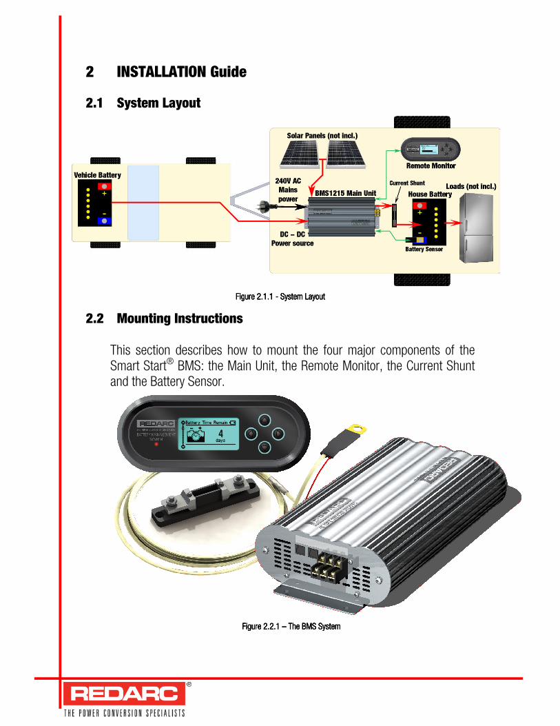
2.1 System Layout
Figure Figure Figure Figure 2222.1.1 .1.1 .1.1 .1.1 ---- System L System L System L System Layoutayoutayoutayout
2.2 Mounting Instructions
This section describes how to mount the four major components of the Smart Start® BMS: the Main Unit, the Remote Monitor, the Current Shunt and the Battery Sensor.
Figure 2.2.1 Figure 2.2.1 Figure 2.2.1 Figure 2.2.1 –––– The BMS System The BMS System The BMS System The BMS System

2.2.1 Mounting the Main Unit
Do NOT expose the Main Unit to rain, snow, spray or bilge water. For optimum operation, the Smart Start® BMS should be mounted where the temperature is nominally below 35°C and does not exceed a maximum of 60°C. The Main Unit must not be installed in a location with any less than 10cm clearance at the top of the Main Unit, to allow for airflow across the heatsink fins. Care must be taken not to obstruct the ventilation holes at the end of the Main Unit. The Main Unit should be installed as close as possible to the house battery. The cable length should be less than 2m. The Main Unit must be mounted to a solid support, preferably the vehicle chassis, using M6 sized screws or bolts, using all four mounting holes.
WARNING The Main Unit must be fixed using suitable screw mounts. Do NOT use adhesive to mount the unit because this is unreliable.
Redarc recommends that the Main Unit be mounted to optimise airflow past the heatsink. Mounting the unit horizontally (see Figures 2.2.1.1 and 2.2.1.2) is acceptable. Do NOT mount the unit as shown in Figure 2.2.1.3 or Figure 2.2.1.4.
Figure 2.2Figure 2.2Figure 2.2Figure 2.2.1..1..1..1.1111 –––– Horizontal Horizontal Horizontal Horizontal mounting: acceptablemounting: acceptablemounting: acceptablemounting: acceptable
Figure 2.Figure 2.Figure 2.Figure 2.2.1.2.1.2.1.2.1.2222 –––– Horizontal Horizontal Horizontal Horizontal mounting: acceptablemounting: acceptablemounting: acceptablemounting: acceptable
Figure 2.Figure 2.Figure 2.Figure 2.2.1.2.1.2.1.2.1.4444 –––– Do NOT Do NOT Do NOT Do NOT mount the unit this wamount the unit this wamount the unit this wamount the unit this wayyyy
Figure 2.2.1.3 Figure 2.2.1.3 Figure 2.2.1.3 Figure 2.2.1.3 –––– Do NOT Do NOT Do NOT Do NOT mount the unit this waymount the unit this waymount the unit this waymount the unit this way

2.2.2 Mounting the Remote Monitor
The Remote Monitor should be mounted inside the caravan or RV. It is acceptable, however, to mount the Remote Monitor in any convenient location. Figures 2.2.2.1 and 2.2.2.2 illustrate how to wall mount and flush mount the Remote Monitor unit.
Wall Mount
1111 Use the template providedUse the template providedUse the template providedUse the template provided to mark position, to mark position, to mark position, to mark position, and and and and drill mounting holes into the wall.drill mounting holes into the wall.drill mounting holes into the wall.drill mounting holes into the wall.
2 2 2 2 Feed the Remote CFeed the Remote CFeed the Remote CFeed the Remote Cable through the hole able through the hole able through the hole able through the hole provided & provided & provided & provided & mmmmount the Back Plate to the wall.ount the Back Plate to the wall.ount the Back Plate to the wall.ount the Back Plate to the wall.
3333 Connect the Remote cableConnect the Remote cableConnect the Remote cableConnect the Remote cable to the Remote & to the Remote & to the Remote & to the Remote & cccclip the Inner Assembly to the Back Plate.lip the Inner Assembly to the Back Plate.lip the Inner Assembly to the Back Plate.lip the Inner Assembly to the Back Plate.
4444 Clip the Front Face to the Inner AssemblyClip the Front Face to the Inner AssemblyClip the Front Face to the Inner AssemblyClip the Front Face to the Inner Assembly. . . . Remote is now Wall Mounted.Remote is now Wall Mounted.Remote is now Wall Mounted.Remote is now Wall Mounted.
Figure 2.Figure 2.Figure 2.Figure 2.2.2.12.2.12.2.12.2.1 –––– How to wall mount How to wall mount How to wall mount How to wall mount the Remote Controlthe Remote Controlthe Remote Controlthe Remote Control
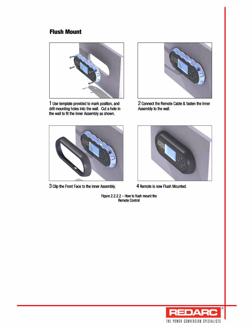
Flush Mount
1111 Use templateUse templateUse templateUse template provided provided provided provided to mark position, and to mark position, and to mark position, and to mark position, and drill mounting holes into the wall. drill mounting holes into the wall. drill mounting holes into the wall. drill mounting holes into the wall. Cut a hole in Cut a hole in Cut a hole in Cut a hole in the wall to fit the Inner Asthe wall to fit the Inner Asthe wall to fit the Inner Asthe wall to fit the Inner Assembly as shown.sembly as shown.sembly as shown.sembly as shown.
2222 Connect the Remote Cable & fConnect the Remote Cable & fConnect the Remote Cable & fConnect the Remote Cable & fasten the Inner asten the Inner asten the Inner asten the Inner Assembly to the wall.Assembly to the wall.Assembly to the wall.Assembly to the wall.
3333 Clip the Front Face to the Inner Assembly.Clip the Front Face to the Inner Assembly.Clip the Front Face to the Inner Assembly.Clip the Front Face to the Inner Assembly. 4444 Remote is now Flush Mounted.Remote is now Flush Mounted.Remote is now Flush Mounted.Remote is now Flush Mounted.
Figure 2.Figure 2.Figure 2.Figure 2.2.2.22.2.22.2.22.2.2 –––– How to flush mount the How to flush mount the How to flush mount the How to flush mount the ReReReRemote Controlmote Controlmote Controlmote Control

2.2.3 Installing the Current Shunt Bolt the Current Shunt between the negative negative negative negative terminal of the house battery and the common negative terminal block using the outside connections as shown in figure 2.2.3.1. Connect the sense terminals on the Battery Management System to the Current Shunt with a twisted pair of wires. The shunt positive wire is connected to the screw terminal on the end of the Current Shunt closest to the house battery. The shunt negative terminal on the Smart Start® BMS must be fixed under the screw terminal on the Current Shunt nearest the common negative connection.
2.2.4 Installing the Battery Sensor
Bolt the large lug of the Battery Sensor to the negative negative negative negative terminal of the house battery, with the ring terminal of the red wire bolted to the positivepositivepositivepositive terminal of the house battery as shown in Figure 2.2.4.1.
Figure 2.2.Figure 2.2.Figure 2.2.Figure 2.2.3.1 3.1 3.1 3.1 –––– Current Shunt Current Shunt Current Shunt Current Shunt InstallationInstallationInstallationInstallation
(Wire sizes not to scale)(Wire sizes not to scale)(Wire sizes not to scale)(Wire sizes not to scale)
Figure 2.2.4.1 Figure 2.2.4.1 Figure 2.2.4.1 Figure 2.2.4.1 –––– Battery Sensor Battery Sensor Battery Sensor Battery Sensor InstallationInstallationInstallationInstallation
(Wire sizes not to scale)(Wire sizes not to scale)(Wire sizes not to scale)(Wire sizes not to scale)

2.3 DC Cable Size Requirements
WARNING Cable and fuse sizes are specified by various codes and standards which depend on the type of vehicle the unit is installed into. Selecting the wrong cable or fuse size could result in harm to the installer or user and/or damage to the Smart Start® BMS or other equipment installed in the system. The installer is responsible for ensuring that the correct cable and fuse sizes are used when installing this device.
Input Wire Diameter Selection The Smart Start® BMS is capable of drawing up to 30A from the vehicle battery, which may be several metres from its installation location. The installer needs to ensure the appropriate cable is used to connect the positive and negative connections of the Smart Start® BMS to the vehicle battery. While the Smart Start® BMS will operate with less efficient cabling, for best performance, high-quality cable connections should be used to minimise voltage drop and efficiency losses. Redarc recommends the installer use cabling and connections between 6mm automotive and 6B&S. The recommended maximum cable length between input vehicle battery and the Smart Start® BMS should not be longer than 10m for 6mm auto or 20m for 6B&S. Though the Smart Start® BMS will operate with less efficient cabling, Redarc recommends that the input wire be of the size outlined in Table 2.3.1.
Distance (metres) from Distance (metres) from Distance (metres) from Distance (metres) from source battery to source battery to source battery to source battery to
BMS1215BMS1215BMS1215BMS1215
RecommendedRecommendedRecommendedRecommended Diameter Diameter Diameter Diameter [mm[mm[mm[mm2222]]]]
Recommended Diameter Recommended Diameter Recommended Diameter Recommended Diameter EquivalentEquivalentEquivalentEquivalent
1 4 6mm auto 2 6 8 B&S 3 10 6 B&S 4 12 6 B&S 5 + 16 6 B&S
Table 2.3.1 Table 2.3.1 Table 2.3.1 Table 2.3.1 –––– Recommended cable sizes for safe cable heating and efficiency Recommended cable sizes for safe cable heating and efficiency Recommended cable sizes for safe cable heating and efficiency Recommended cable sizes for safe cable heating and efficiency losseslosseslosseslosses

Output Wire Diameter Selection To ensure the house battery is charged as quickly as possible, use the appropriate cable to connect the Smart Start® BMS to the battery to be charged. The Smart Start® BMS should be mounted as close as possible to the battery being charged. Table 2.3.2 lists the recommended cable sizes based on a cable voltage drop of 0.3V @ 15A. Minimum cable size is 2.9 mm² or 5mm auto (less than 1m length). Maximum cable size is 8mm² or 6B&S (no need to use values higher than this). For longer runs using 8mm² is recommended, however this will reduce efficiency below 3% (the recommended maximum length is 5m).
DistanceDistanceDistanceDistance (metres) (metres) (metres) (metres) from from from from BMS1215BMS1215BMS1215BMS1215 to to to to house house house house
batterybatterybatterybattery
Recommended Diameter Recommended Diameter Recommended Diameter Recommended Diameter [mm[mm[mm[mm2222]]]]
Recommended Recommended Recommended Recommended Diameter Diameter Diameter Diameter Equivalent Equivalent Equivalent Equivalent
0.5 2.9 5mm auto 0.75 3.2 6mm auto 1 4 6mm auto
1.25 5 8 B&S 1.5 6 8 B&S 1.75 7 8 B&S 2 8 6 B&S
NOTE: Redarc has determined these recommendNOTE: Redarc has determined these recommendNOTE: Redarc has determined these recommendNOTE: Redarc has determined these recommendedededed cable sizes based cable sizes based cable sizes based cable sizes based on on on on 50505050°C °C °C °C maximum ambient temperature,maximum ambient temperature,maximum ambient temperature,maximum ambient temperature, a single cable loom and a single cable loom and a single cable loom and a single cable loom and dodododoeseseses not include any not include any not include any not include any connection losses. connection losses. connection losses. connection losses. The installer The installer The installer The installer is responsible for is responsible for is responsible for is responsible for ensurensurensurensuringinginging that these cables are that these cables are that these cables are that these cables are indeed suitable for the vehicle installation.indeed suitable for the vehicle installation.indeed suitable for the vehicle installation.indeed suitable for the vehicle installation.
Table 2.Table 2.Table 2.Table 2.3.3.3.3.2222 –––– Recommended cable sizes based on a cable voltage drop of Recommended cable sizes based on a cable voltage drop of Recommended cable sizes based on a cable voltage drop of Recommended cable sizes based on a cable voltage drop of 0.3V @ 15A0.3V @ 15A0.3V @ 15A0.3V @ 15A
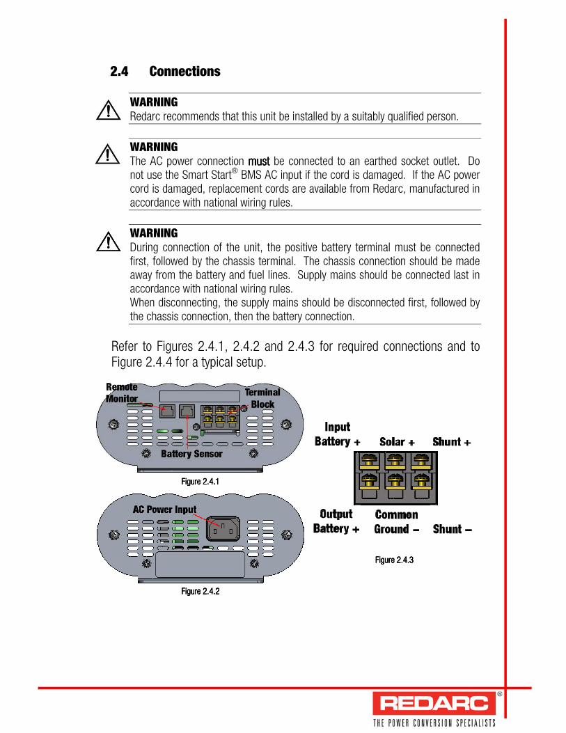
2.4 Connections
WARNING Redarc recommends that this unit be installed by a suitably qualified person.
WARNING The AC power connection mustmustmustmust be connected to an earthed socket outlet. Do not use the Smart Start® BMS AC input if the cord is damaged. If the AC power cord is damaged, replacement cords are available from Redarc, manufactured in accordance with national wiring rules.
WARNING During connection of the unit, the positive battery terminal must be connected first, followed by the chassis terminal. The chassis connection should be made away from the battery and fuel lines. Supply mains should be connected last in accordance with national wiring rules. When disconnecting, the supply mains should be disconnected first, followed by the chassis connection, then the battery connection.
Refer to Figures 2.4.1, 2.4.2 and 2.4.3 for required connections and to Figure 2.4.4 for a typical setup.
Figure 2.Figure 2.Figure 2.Figure 2.4.14.14.14.1
Figure 2.Figure 2.Figure 2.Figure 2.4.24.24.24.2
Figure 2.Figure 2.Figure 2.Figure 2.4.34.34.34.3
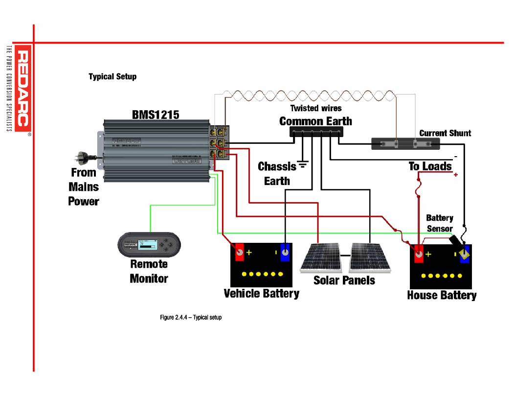
Figure 2.Figure 2.Figure 2.Figure 2.4.4.4.4.4444 –––– Typical setup Typical setup Typical setup Typical setup
Typical Setup

2.5 Batteries
WARNING Explosive gases can be generated by the house battery during the charge process, therefore the battery should be kept in a well ventilated area.
WARNING When charging a battery, make sure the settings at the Battery Setup menu on the Remote Monitor are correct for the type of battery under charge. Charging a battery with the wrong profile may cause the Smart Start® BMS to indicate a fault or give misleading results and could result in damage to the battery. Noticeable oscillations between Boost and Absorption stages indicate the wrong choice of battery type. Check and adjust battery type. If you are unsure of the battery type or settings to use, set the Smart Start® BMS to the Gel setting.
Figure 2.5.1 and 2.5.2 show standard wiring for batteries in series and parallel respectively.
To ensure that all batteries are equally charged, loads and Smart Start® BMS should be connected with ground and 12V power connected diagonally opposite across all batteries as shown in Figure 2.5.1 and 2.5.2.
Figure 2.5.1 – Standard wiring for Standard wiring for Standard wiring for Standard wiring for batteries in seriesbatteries in seriesbatteries in seriesbatteries in series
Figure 2.Figure 2.Figure 2.Figure 2.5.2 5.2 5.2 5.2 –––– Standard wiring for Standard wiring for Standard wiring for Standard wiring for batteries in parallelbatteries in parallelbatteries in parallelbatteries in parallel
2.6 MPPT Solar Regulator
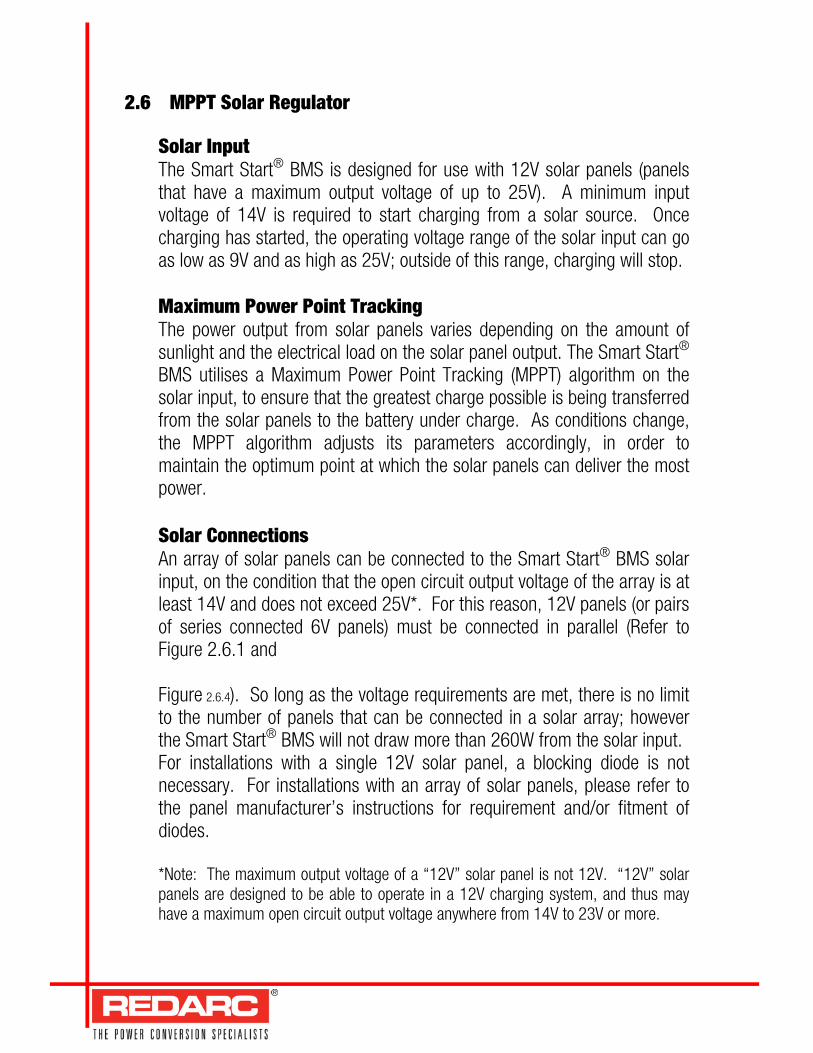
Solar Input The Smart Start® BMS is designed for use with 12V solar panels (panels that have a maximum output voltage of up to 25V). A minimum input voltage of 14V is required to start charging from a solar source. Once charging has started, the operating voltage range of the solar input can go as low as 9V and as high as 25V; outside of this range, charging will stop. Maximum Power Point Tracking The power output from solar panels varies depending on the amount of sunlight and the electrical load on the solar panel output. The Smart Start® BMS utilises a Maximum Power Point Tracking (MPPT) algorithm on the solar input, to ensure that the greatest charge possible is being transferred from the solar panels to the battery under charge. As conditions change, the MPPT algorithm adjusts its parameters accordingly, in order to maintain the optimum point at which the solar panels can deliver the most power. Solar Connections An array of solar panels can be connected to the Smart Start® BMS solar input, on the condition that the open circuit output voltage of the array is at least 14V and does not exceed 25V*. For this reason, 12V panels (or pairs of series connected 6V panels) must be connected in parallel (Refer to Figure 2.6.1 and Figure 2.6.4). So long as the voltage requirements are met, there is no limit to the number of panels that can be connected in a solar array; however the Smart Start® BMS will not draw more than 260W from the solar input. For installations with a single 12V solar panel, a blocking diode is not necessary. For installations with an array of solar panels, please refer to the panel manufacturer’s instructions for requirement and/or fitment of diodes. *Note: The maximum output voltage of a “12V” solar panel is not 12V. “12V” solar panels are designed to be able to operate in a 12V charging system, and thus may have a maximum open circuit output voltage anywhere from 14V to 23V or more.
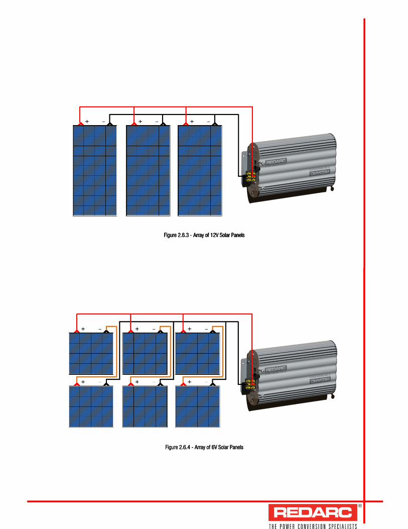
Figure 2.6.Figure 2.6.Figure 2.6.Figure 2.6.3333 ---- Array of 12V Solar Panels Array of 12V Solar Panels Array of 12V Solar Panels Array of 12V Solar Panels
Figure 2.6.Figure 2.6.Figure 2.6.Figure 2.6.4444 ---- Array of 6V Solar Panels Array of 6V Solar Panels Array of 6V Solar Panels Array of 6V Solar Panels

3 USER Guide
3.1 Remote Monitor
The Remote Monitor is designed to give you control of how the battery is being charged, as well as up-to-date house battery and charge information at any time during the charging process. You can check battery charge status, estimated charge time and State of Charge (SOC) per hour over a day and per day over a month. It also allows you to select charging profiles specific to the battery type and size. The four controls ‘Up’, ‘Down’, ‘Enter’ and ‘Exit’ allow you to select options or move in and out of menu items.
3.2 Understanding the Display
The top left corner of the screen always displays the title of the present menu. Use the ‘Up’ and ‘Down’ buttons to move between menus and to change settings such as battery type and contrast level. At any time during operation, the ‘Exit’ button will take you back to the last level, unless otherwise specified. At any time during operation, the menu at the bottom of the screen will explain the function of the ‘Enter’ and ‘Exit’ buttons.
Figure 3.1.1 Figure 3.1.1 Figure 3.1.1 Figure 3.1.1 –––– The Remote Control The Remote Control The Remote Control The Remote Control
Figure 3.2.1 Figure 3.2.1 Figure 3.2.1 Figure 3.2.1 –––– The LCD Display The LCD Display The LCD Display The LCD Display

3.3 Navigating the Menu
The Smart Start® BMS monitors current in and out of the house battery, keeping track of the charge remaining in the battery. This screen displays the estimated state of charge of the house battery in percentage along with a bar graph. During and for the duration of the initial charge cycle for a new battery this screen will show ‘Analysing’. This is when the Smart Start® BMS is gathering information about the battery under charge. Press the ‘Enter’ key to view the State of Charge (SOC) graphs by hour or by day.
These screens display the State of Charge of the battery under charge per hour across the course of the last day, or per day across the course of the last month. These screens will record the present State of Charge for the hour and the maximum and minimum States of Charge for the day and display them at the bottom of the screen as shown. Pressing the ‘Up’ key at this screen will take you to the State of Charge screen for the previous hour or day. Similarly, pressing the ‘Down’ key at this screen will take you to the State of Charge screen for the next hour or day. The most recent day or hour is always numbered as 1, and is the left most line on the graph. Pressing the ‘Exit’ button from the SOC by day screen will take you back to the SOC by hour screen. Pressing the ‘Exit’ button from the SOC by hour screen will take you back to the Charge Status screen. Pressing ‘Down’ from the Charge Status screen will take you to the Battery Status screen.
This screen will display either the Time to Full Charge or the Battery Time Remaining, depending on whether the house battery is currently being charged or discharged. The Smart Start® BMS uses the estimated State of Charge value to calculate - based on the current into or out of the house battery - the time to reach 100% State of Charge. You may use this to decide when to disconnect AC power, for example. Similarly, the Smart Start® BMS uses the estimated State of Charge value to calculate - based on the power usage of the system (e.g. of loads such as fridges, lighting) - the useful time remaining of the battery. Pressing ‘Down’ from the Battery Status screen will take you to the Charge Mode screen.

The Smart Start® BMS can be configured via this setting to use either a 3-stage (Touring) or a 5-stage (Storage) charging mode to get the best charge for the situation. Storage mode should only be used while loads are turned off (such as when the caravan is in storage). It will perform an equalise charge on your battery as well as performing health checks on the house battery. Touring mode will maintain charge output as much as possible and will only perform critical status checks to ensure maximum charge is output to the house battery from your source (while on the road or when loads are connected). Pressing the ‘Enter’ key at any of these screens will give you the option of changing the charge mode.
While at this screen, pressing ‘Up’ or ‘Down’ will change the mode, and pressing the ‘Enter’ key will confirm the change. When changing from Touring to Storage mode, a Caution screen will appear, asking you to disconnect all loads. This must be done before selecting storage mode, as the Storage charging profile requires no interference from system loads during the charging process. Pressing the ‘Exit’ key at this Caution screen will cancel the change. Press ‘Down’ from the Charge Mode screen to display the Charge Source screen.
IMPORTANT When changing the charge mode from Touring to Storage, make sure that all loads are disconnected from the house battery under charge. Failure to do so may cause the house battery to be under charged, give false readings on the State of Charge indicator and possibly cause damage to any loads connected to the system.
This menu displays the selected input source for the battery charger. The Smart Start® BMS operates on a charge priority setup, with AC being the highest priority, followed by DC and then Solar. Pressing ‘Down’ from the Charge Source screen will take you to the Charge Status screen.
�
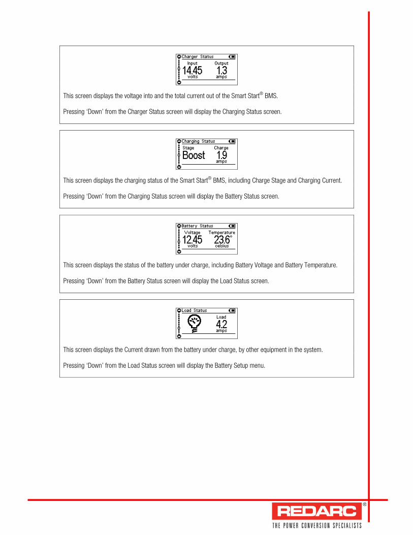
This screen displays the voltage into and the total current out of the Smart Start® BMS. Pressing ‘Down’ from the Charger Status screen will display the Charging Status screen.
This screen displays the charging status of the Smart Start® BMS, including Charge Stage and Charging Current. Pressing ‘Down’ from the Charging Status screen will display the Battery Status screen.
This screen displays the status of the battery under charge, including Battery Voltage and Battery Temperature. Pressing ‘Down’ from the Battery Status screen will display the Load Status screen.
This screen displays the Current drawn from the battery under charge, by other equipment in the system. Pressing ‘Down’ from the Load Status screen will display the Battery Setup menu.

The first screen in this menu displays the selected battery settings for the battery under charge. Pressing the ‘Enter’ key allows you to edit these settings. The menu will ask what type of battery is going to be charged, followed by what the size of the battery is. When you have chosen these values, the menu will ask for confirmation of the settings while displaying them on the screen. Pressing ‘Enter’ at this screen will confirm the settings and return to the Battery Setup screen. Pressing ‘Down’ from the Battery Setup screen will display the Basic Settings menu.
WARNING When charging a battery, make sure the settings at the Battery Setup menu on the Remote Monitor are correct for the type of battery under charge. Charging a battery with the wrong profile may cause the Smart Start® BMS to indicate a fault and could result in damage to the battery. If you are unsure what battery type or settings to use, set the Smart Start® BMS to the Gel setting. These settings should be reviewed and/or changed every time the battery is connected to the Smart Start® BMS.
Via this menu, you can change settings relating to the Remote Display and its operation. Pressing the ‘Enter’ key at this screen allows you to configure settings for Contrast, Brightness, Temperature and Keypad Tones as well as restoring the Factory Settings of the Smart Start® BMS. Pressing ‘Enter’ at this menu will display the Basic Settings menu items. Pressing ‘Down’ at this screen will return to the Charge Status screen.
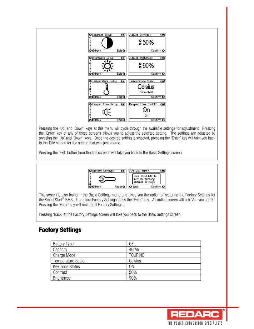
Pressing the ‘Up’ and ‘Down’ keys at this menu will cycle through the available settings for adjustment. Pressing the ‘Enter’ key at any of these screens allows you to adjust the selected setting. The settings are adjusted by pressing the ‘Up’ and ‘Down’ keys. Once the desired setting is selected, pressing the ‘Enter’ key will take you back to the Title screen for the setting that was just altered. Pressing the ‘Exit’ button from the title screens will take you back to the Basic Settings screen.
This screen is also found in the Basic Settings menu and gives you the option of restoring the Factory Settings for the Smart Start® BMS. To restore Factory Settings press the ‘Enter’ key. A caution screen will ask ’Are you sure?’. Pressing the ‘Enter’ key will restore all Factory Settings. Pressing ‘Back’ at the Factory Settings screen will take you back to the Basic Settings screen.
Factory Settings
Battery Type GEL Capacity 40 Ah Charge Mode TOURING Temperature Scale Celsius Key Tone Status ON Contrast 50% Brightness 90%

If the Smart Start® BMS detects a problem with the charging system that doesdoesdoesdoes notnotnotnot preventpreventpreventprevent itititit from charging the battery, it will alert you via a Warning screen and an alarm buzzer, and continue charging. The screen will give a brief description of the problem and allow you to select either ‘Clear’ or ‘Ignore’ via the ‘Enter’ and ‘Exit’ buttons. Both options will clear the warning screen. After selecting ‘Clear’, however, the Smart Start® BMS will immediately check to see if the fault condition still exists. If it does, it will display the warning screen again. Selecting ‘Ignore’ will prevent the Smart Start® BMS from detecting the same fault for up to one minute. NOTE: If “Ignore” is selected but the fault is not removed, when the warning re-appears after one minute, it will not not not not be accompanied by the alarm buzzer. The troubleshooting section of this manual contains a description of faults detected.
If the Smart Start® BMS detects a problem with the charging system that preventpreventpreventpreventssss it it it it from continuing to charge the
battery, it will alert you via a ‘Fault’ screen and an alarm buzzer, and will instantly terminate the charging cycle until
the fault condition is cleared. The screen will give a brief description of the problem and will allow you to select
either ‘Clear’ or ‘Ignore’ via the ‘Enter’ and ‘Exit’ buttons. Both options will clear the fault screen. After selecting
‘Clear’, however, the Smart Start® BMS will immediately check to see if the fault condition still exists. If it doesn’t,
the unit will restart charging. Selecting ‘Ignore’ will simply hide the fault screen for up to one minute. It will not
allow the Smart Start® BMS to recommence charging unless the Smart Start® BMS itself detects the removal of the
fault condition.
NOTE: If “Ignore” is selected but the fault is not removed, when the warning re-appears after one minute, it will not not not not be accompanied by the alarm buzzer. The troubleshooting section of this manual contains a description of faults detected.
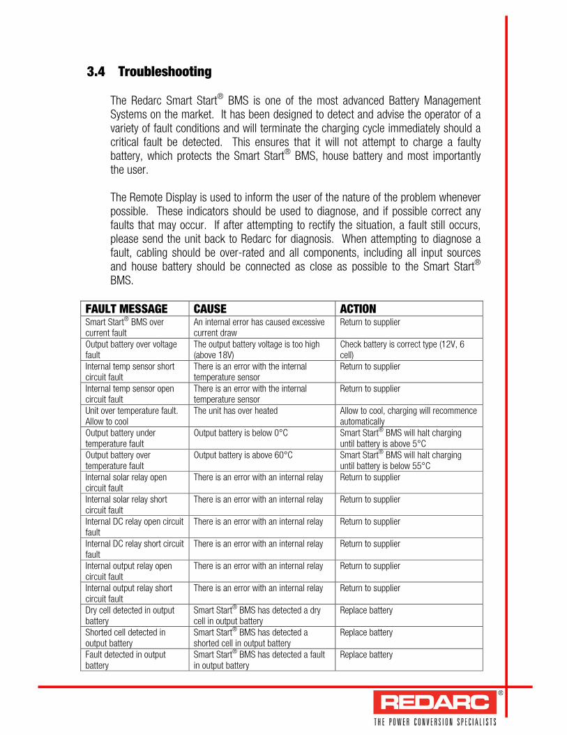
3.4 Troubleshooting The Redarc Smart Start® BMS is one of the most advanced Battery Management Systems on the market. It has been designed to detect and advise the operator of a variety of fault conditions and will terminate the charging cycle immediately should a critical fault be detected. This ensures that it will not attempt to charge a faulty battery, which protects the Smart Start® BMS, house battery and most importantly the user. The Remote Display is used to inform the user of the nature of the problem whenever possible. These indicators should be used to diagnose, and if possible correct any faults that may occur. If after attempting to rectify the situation, a fault still occurs, please send the unit back to Redarc for diagnosis. When attempting to diagnose a fault, cabling should be over-rated and all components, including all input sources and house battery should be connected as close as possible to the Smart Start® BMS.
FAULT MESSAGE CAUSE ACTION Smart Start® BMS over current fault
An internal error has caused excessive current draw
Return to supplier
Output battery over voltage fault
The output battery voltage is too high (above 18V)
Check battery is correct type (12V, 6 cell)
Internal temp sensor short circuit fault
There is an error with the internal temperature sensor
Return to supplier
Internal temp sensor open circuit fault
There is an error with the internal temperature sensor
Return to supplier
Unit over temperature fault. Allow to cool
The unit has over heated Allow to cool, charging will recommence automatically
Output battery under temperature fault
Output battery is below 0°C Smart Start® BMS will halt charging until battery is above 5°C
Output battery over temperature fault
Output battery is above 60°C Smart Start® BMS will halt charging until battery is below 55°C
Internal solar relay open circuit fault
There is an error with an internal relay Return to supplier
Internal solar relay short circuit fault
There is an error with an internal relay Return to supplier
Internal DC relay open circuit fault
There is an error with an internal relay Return to supplier
Internal DC relay short circuit fault
There is an error with an internal relay Return to supplier
Internal output relay open circuit fault
There is an error with an internal relay Return to supplier
Internal output relay short circuit fault
There is an error with an internal relay Return to supplier
Dry cell detected in output battery
Smart Start® BMS has detected a dry cell in output battery
Replace battery
Shorted cell detected in output battery
Smart Start® BMS has detected a shorted cell in output battery
Replace battery
Fault detected in output battery
Smart Start® BMS has detected a fault in output battery
Replace battery
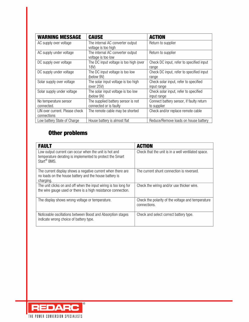
WARNING MESSAGE CAUSE ACTION AC supply over voltage The internal AC converter output
voltage is too high Return to supplier
AC supply under voltage The internal AC converter output voltage is too low
Return to supplier
DC supply over voltage The DC input voltage is too high (over 18V)
Check DC input, refer to specified input range
DC supply under voltage The DC input voltage is too low (below 9V)
Check DC input, refer to specified input range
Solar supply over voltage The solar input voltage is too high (over 25V)
Check solar input, refer to specified input range
Solar supply under voltage The solar input voltage is too low (below 9V)
Check solar input, refer to specified input range
No temperature sensor connected.
The supplied battery sensor is not connected or is faulty
Connect battery sensor, if faulty return to supplier
LIN over current. Please check connections
The remote cable may be shorted Check and/or replace remote cable
Low battery State of Charge House battery is almost flat Reduce/Remove loads on house battery
Other problems
FAULT ACTION Low output current can occur when the unit is hot and temperature derating is implemented to protect the Smart Start® BMS.
Check that the unit is in a well ventilated space.
The current display shows a negative current when there are no loads on the house battery and the house battery is charging.
The current shunt connection is reversed.
The unit clicks on and off when the input wiring is too long for the wire gauge used or there is a high resistance connection.
Check the wiring and/or use thicker wire.
The display shows wrong voltage or temperature.
Check the polarity of the voltage and temperature connections.
Noticeable oscillations between Boost and Absorption stages indicate wrong choice of battery type.
Check and select correct battery type.


TWO YEAR WARRANTY
REDARC Electronics warrants to REDARC Electronics warrants to REDARC Electronics warrants to REDARC Electronics warrants to the original purchaser that the product(s) on the reverse side of this sheet ("Product") will be free, under normal use and the original purchaser that the product(s) on the reverse side of this sheet ("Product") will be free, under normal use and the original purchaser that the product(s) on the reverse side of this sheet ("Product") will be free, under normal use and the original purchaser that the product(s) on the reverse side of this sheet ("Product") will be free, under normal use and
maintenance, from defects in material and workmanship for a period of TWO YEARS from the date of purchase, subject to the conditionsmaintenance, from defects in material and workmanship for a period of TWO YEARS from the date of purchase, subject to the conditionsmaintenance, from defects in material and workmanship for a period of TWO YEARS from the date of purchase, subject to the conditionsmaintenance, from defects in material and workmanship for a period of TWO YEARS from the date of purchase, subject to the conditions shown below. shown below. shown below. shown below.
1.1.1.1. WarrantyWarrantyWarrantyWarranty
Unless otherwise stated in this warranty, Redarc Electronics will at its sole discretion either replace or repair any of the Product that is defective in material
or workmanship within the abovementioned period without charge to the original purchaser.
2.2.2.2. Other WarrantyOther WarrantyOther WarrantyOther Warranty
Subject to any terms implied by law, this warranty contains the whole of the Redarc Electronics' obligations and any distributor and the agents, officers
and employees of such distributor and of Redarc Electronics are not authorised to vary or extend the terms of the warranty. The benefits conferred by this
warranty are in addition to the conditions and warranties implied by applicable legislation conferring rights upon consumers, which apply only to the extent
to which they may not by law be excluded.
3.3.3.3. ExclusionsExclusionsExclusionsExclusions
This warranty shall not apply to, or include, any of the following:
3.1 Any defect or failure due to accident, misuse, abuse, movement of the Product to a new site, negligence, non-observance of any of the
instructions supplied with the Product including the instructions on the reverse side of this sheet ("Operating Instructions") or local regulations on
the part of any user, choice of location, improper installation, configuration or connection, or faulty power supply.
3.2 If the Product is installed, repaired or serviced by a person who is not a qualified auto electrician or electronics technician, or if non-approved parts
have been fitted.
3.3 Failure to obtain proper maintenance for the Product or any associated equipment or machinery.
3.4 Failure to pay for the products in full or comply with Redarc Electronics' Trading Terms.
3.5 If the Product is used other than for any reasonable purpose for which it was manufactured, or is used in a way not specified by Redarc
Electronics.
3.6 If the original purchaser sells, leases or otherwise parts with possession of the Product.
3.7 Deterioration due to normal use and exposure, including abnormal environmental conditions such as lightning strike, flood and extreme heat.
3.8 Any freight, packing and insurance expenses relating to transportation of the Product.
3.9 Any expenses relating to installation and/or removal of the Product.
3.10 Any damage, indirect or incidental, of whatever nature.
4.4.4.4. LimitationsLimitationsLimitationsLimitations
4.1 Redarc Electronics is not liable for any consequential, indirect or accidental loss or damage or for any service not expressly provided herein
(including without limitation liability for any loss or damage caused by a fault in the Product or its external wiring connections) and the liability of
Redarc Electronics under this warranty is limited to the repair or replacement of defective material or workmanship by a qualified auto electrician
or electronics technician, provided such person and work is approved by Redarc prior to commencement. Subject to clause 2clause 2clause 2clause 2, Redarc Electronics
is hereby excluded to the maximum extent permitted by law from all other liability in respect of the Product.
4.2 While Redarc Electronics warrants, where applicable, that the Product is free from defects in materials and workmanship under normal use at the
time of delivery, Redarc Electronics does not warrant that the Product will meet any user specific requirements or that the operation of the Product
will be uninterrupted or error-free.
5.5.5.5. Owner’s ResponsibilitiesOwner’s ResponsibilitiesOwner’s ResponsibilitiesOwner’s Responsibilities
5.1 Maintenance of the Product and associated equipment and/or machinery is the responsibility of the owner. The owner must retain evidence that
proper maintenance has been performed on the Product by Redarc Electronics or a qualified auto electrician or electronics technician. Claims
made during the warranty term will not be accepted if resulting from lack of maintenance rather than faulty material or workmanship.
5.2 The owner must operate the Product in accordance with all of the Operating Instructions.
5.3 Upon discovery of a fault the owner must return the Product to the distributor with full details of the nature of the fault. Removal of the Product
must be done by a qualified auto electrician or electronics technician to ensure that the warranty remains valid. A written report describing the
circumstances of failure must accompany the returned Product with proof of purchase which clearly shows the date of such purchase by the
original purchaser.
5.4 If the Product is found to be working satisfactorily on return to Redarc Electronics, a reasonable charge will be made for the cost of testing,
packing and freight. The Product will be returned on receipt of the amount charged.
R:\Redarc Product Spec Sheets NEW\Battery Management System\BMS1215 Instruction Manual-A5-I.doc