battery service manual - d2z4qs2e3spnc1.cloudfront.net
TRANSCRIPT
330565Rev. 00 (5--00)
Service Manual
3640E

This service manual is intended to be an aid for the disassembly and reassembly of your TENNANTModel 3640E walk behind sweeper.
The set is organized into four major groups: General Information, Chassis, Sweeping, and Electrical.
General Information: Safety precautions, machine transport, machine jacking, machine storage, chassislubrication, machine specifications, and machine maintenance chart.
Chassis: Tire/wheel replacement, caster replacement, and transaxle repair.
Sweeping: Hopper repair/replacement, brush repair/replacement, skirt/seal repair/replacement, andsweeping troubleshooting.
Electrical: Battery maintenance and replacement, electric motor removal, electrical schematics, andelectrical troubleshooting.
Manual Number -- 330565
Revision: 00
Published: 5--00
Copyright E 2000 TENNANT, Printed in U.S.A.

GENERAL INFORMATION
1--13640E 330565 (5--00)
CONTENTS
Page
SAFETY PRECAUTIONS 1--3. . . . . . . . . . . . . .SPECIFICATIONS 1--5. . . . . . . . . . . . . . . . . . . .GENERAL MACHINE
DIMENSIONS/CAPACITIES 1--5. . . . . . . . .GENERAL MACHINE PERFORMANCE 1--5. .
POWER TYPE 1--6. . . . . . . . . . . . . . . . . . . . .TIRES 1--6. . . . . . . . . . . . . . . . . . . . . . . . . . . .
MACHINE DIMENSIONS 1--7. . . . . . . . . . . . . . .MAINTENANCE 1--8. . . . . . . . . . . . . . . . . . . . . .
MAINTENANCE CHART 1--8. . . . . . . . . . . .PUSHING OR TOWING MACHINE 1--9. . .
MACHINE TIE DOWNS 1--10. . . . . . . . . . . . . . .MACHINE STORAGE 1--10. . . . . . . . . . . . . . . .STATIC DRAG CHAIN 1--12. . . . . . . . . . . . . . . .HARDWARE INFORMATION 1--13. . . . . . . . . .
STANDARD BOLT TORQUE CHART 1--13METRIC BOLT TORQUE CHART 1--13. . .BOLT IDENTIFICATION 1--13. . . . . . . . . . . .THREAD SEALANT AND LOCKING
COMPOUNDS 1--13. . . . . . . . . . . . . . . . .

GENERAL INFORMATION
1--2 3640E 330565 (5--00)
GENERAL INFORMATION
1--33640E 330565 (5--00)
SAFETY PRECAUTIONS
The following symbols are used throughout thismanual as indicated in their description:
WARNING: To warn of hazards orunsafe practices that could result insevere personal injury or death.
FOR SAFETY: To identify actions thatmust be followed for safe operation ofequipment.
The machine is suited to sweep disposabledebris. Do not use the machine other thandescribed in this Operator Manual. The machineis not designed for use on public roads.
The following information signals potentiallydangerous conditions to the operator orequipment:
FOR SAFETY:
1. Do not operate machine:-- Unless trained and authorized.-- Unless operation manual is read and
understood.-- In flammable or explosive areas unless
designed for use in those areas.
2. When starting machine:-- Keep directional lever in Park position.
3. When using machine:-- Go slowly on inclines and slippery
surfaces.-- Use care when reversing machine.-- Do not carry riders on machine.-- Always follow safety and traffic rules.-- Report machine damage or faulty
operation immediately.
4. Before leaving or servicing machine:-- Stop on level surface.-- Move directional lever into Park
position.-- Turn off machine and remove key.
5. When servicing machine:-- Avoid moving parts. Do not wear loose
jackets, shirts, or sleeves whenworking on machine.
-- Wear eye and ear protection if usingpressurized air or water.
-- Disconnect battery connections beforeworking on machine.
-- Avoid contact with battery acid.-- Use Tennant supplied or equivalent
replacement parts.
WARNING: Heavy hopper. Get help tohandle.
WARNING: Brush throws debris. Stopmotor before lifting hopper.
WARNING: Moving belt and fan. Keepaway.
WARNING: Batteries emit hydrogen gas.Explosion or fire can result. Keepsparks and open flame away. Keepcovers open when charging.

GENERAL INFORMATION
1--4 3640E 330565 (5--00)
The following safety labels are mounted on themachine in the locations indicated. If these or anylabels become damaged or illegible, install a newlabel in its place.
BATTERY CHARGING LABEL --LOCATED ON THE UNDERSIDE OFTHE BATTERY COMPARTMENT COVER
FOR SAFETY LABEL -- LOCATEDON THE CONTROL PANEL
BACK STRAIN LABEL -- LOCATED ON THEMOTOR COMPARTMENT COVER
FLYING DEBRIS WARNING LABEL -- LOCATEDON THE MOTOR COMPARTMENT COVER
350842
GENERAL INFORMATION
1--53640E 330565 (5--00)
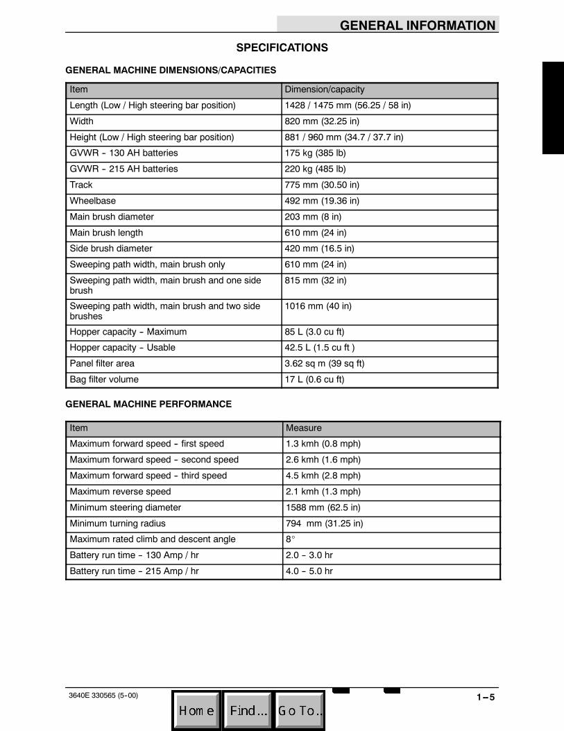
SPECIFICATIONS
GENERAL MACHINE DIMENSIONS/CAPACITIES
Item Dimension/capacity
Length (Low / High steering bar position) 1428 / 1475 mm (56.25 / 58 in)
Width 820 mm (32.25 in)
Height (Low / High steering bar position) 881 / 960 mm (34.7 / 37.7 in)
GVWR -- 130 AH batteries 175 kg (385 lb)
GVWR -- 215 AH batteries 220 kg (485 lb)
Track 775 mm (30.50 in)
Wheelbase 492 mm (19.36 in)
Main brush diameter 203 mm (8 in)
Main brush length 610 mm (24 in)
Side brush diameter 420 mm (16.5 in)
Sweeping path width, main brush only 610 mm (24 in)
Sweeping path width, main brush and one sidebrush
815 mm (32 in)
Sweeping path width, main brush and two sidebrushes
1016 mm (40 in)
Hopper capacity -- Maximum 85 L (3.0 cu ft)
Hopper capacity -- Usable 42.5 L (1.5 cu ft )
Panel filter area 3.62 sq m (39 sq ft)
Bag filter volume 17 L (0.6 cu ft)
GENERAL MACHINE PERFORMANCE
Item Measure
Maximum forward speed -- first speed 1.3 kmh (0.8 mph)
Maximum forward speed -- second speed 2.6 kmh (1.6 mph)
Maximum forward speed -- third speed 4.5 kmh (2.8 mph)
Maximum reverse speed 2.1 kmh (1.3 mph)
Minimum steering diameter 1588 mm (62.5 in)
Minimum turning radius 794 mm (31.25 in)
Maximum rated climb and descent angle 8_
Battery run time -- 130 Amp / hr 2.0 -- 3.0 hr
Battery run time -- 215 Amp / hr 4.0 -- 5.0 hr

GENERAL INFORMATION
1--6 3640E 330565 (5--00)
POWER TYPE
Type Quantity Volts Ah Rating Weight
Batteries 2 12 130 @ 20 hr rate 30 kg (67 lb)
2 12 215 @ 20 hr rate 47 kg (104 lb)
Type Use VDC / Amp Kw (hp)
Electric Motors Side brush(es) (disk) 24 V / 2.4 A 0.075 kw (0.1 hp)Electric Motors
Main motor 24 V / 43 A 0.75 kw(1 hp)
Type VDC Amp Hz Phase VAC
Charger (Smart) 24 15 or 20 50 / 60 1 120 /240
TIRES
Location Type Size
Front (2) Casters 35 mm wide x 127 mm OD (1.375 in wide x 5 in OD)
Rear (2) Solid 45 mm wide x 305 mm OD (1.75 in wide x 12 in OD)
GENERAL INFORMATION
1--73640E 330565 (5--00)
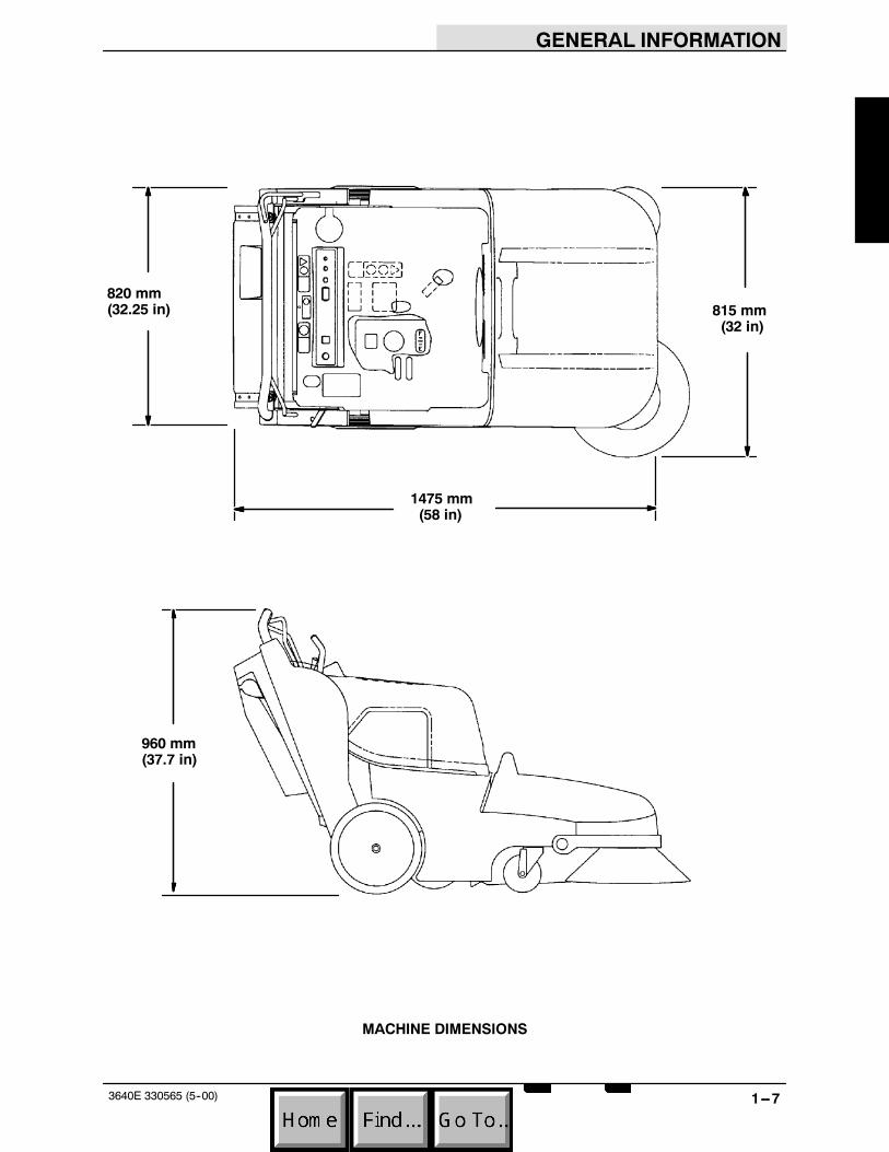
960 mm(37.7 in)
820 mm(32.25 in) 815 mm
(32 in)
1475 mm(58 in)
MACHINE DIMENSIONS

GENERAL INFORMATION
1--8 3640E 330565 (5--00)
MAINTENANCE
1
2
3
4
5
6
350842
MAINTENANCE CHART
Interval Key Description ProcedureLubricant/
Fluid
No. ofServicePoints
Daily 1 Battery cells Check electrolyte level aftercharging
DW 2
4,5 Main brush and sidebrush(es)
Check for damage and wear -- 2 (3)
2 Vacuum inlet plate Check / clean -- 12 Skirts and seals Inspect -- 66 Bag filter Check / Replace if full -- 16 Panel filter (option) Shake filter, clean compartment
door-- 1
50 Hours 1 Vacuum fan belt Check tension and wear -- 150 Hours5 Main brush Rotate end for end and check
brush pattern-- 1
1 Battery cells Check electrolyte level DW 3100 Hours 6 Panel filter (option) Remove and clean -- 1200 Hours 1 Battery terminals Clean and tighten -- 4500 Hours 3 Side brush motor(s) Check motor brush -- 1 (2)1000Hours
1 Main motor Check motor brush -- 1
LUBRICANT/FLUIDDW Distilled water. . . .

GENERAL INFORMATION
1--93640E 330565 (5--00)
PUSHING OR TOWING MACHINE
FOR SAFETY: Before Leaving Or ServicingMachine; Stop On Level Surface, Place ShifterIn Park.
1. Raise the main and side brushes.
2. Place the shift lever in the neutral position.(between reverse and second gear)
3. Push the machine using the handleassembly.

GENERAL INFORMATION
1--10 3640E 330565 (5--00)
MACHINE TIE DOWNS
FOR SAFETY: Before Leaving Or ServicingMachine; Stop On Level Surface, Place ShifterIn Park.
Secure the machine for transport by strapping it tothe floor. Place one strap over the hopper andsecure it by the casters. Place another strap overthe motor compartment and secure it by the rearwheels. Make sure the directional lever is in thepark position.
MACHINE STORAGE
When storing the machine for extended periods oftime, the following procedures must be followed:
1. Raise the main and side brush(es).
2. Empty and clean the debris hopper.

GENERAL INFORMATION
1--113640E 330565 (5--00)
3. Fully charge the batteries.
4. Disconnect the machine connector from thebattery connector.
5. Store the machine in a clean dry area.
07224

GENERAL INFORMATION
1--12 3640E 330565 (5--00)
STATIC DRAG CHAIN
The static drag chain prevents the buildup ofstatic electricity in the machine. The chain isattached to the backstop bracket.
Make sure the chain is always touching the floor.
Always use a internal tooth lock washer betweenthe chain and rear guard to ensure a properelectrical connection.

GENERAL INFORMATION
1--133640E 330565 (5--00)
HARDWARE INFORMATION
The following charts state standard platedhardware tightening ranges for normal assemblyapplications. Decrease the specified torque by20% when using a thread lubricant. Do notsubstitute lower grade hardware for higher gradehardware. If higher grade hardware than specifiedis substituted, tighten only to the specifiedhardware torque value to avoid damaging thethreads of the part being threaded into, as whenthreading into speed nuts or weldments.
STANDARD BOLT TORQUE CHART
ThreadSize
SAE Grade 5Torque ft lb
(Nm)
SAE Grade 8Torque ft lb
(Nm)
0.25 in 7--10 (9--14) 10--13 (14--38)
0.31 in 15--20 (20--27) 20--26 (27--35)
0.38 in 27--35 (37--47) 36--47 (49--64)
0.44 in 43--56 (58--76) 53--76 (72--103)
0.50 in 65--85 (88--115) 89--116(121--157)
0.62 in 130--170(176--231)
117--265(159--359)
0.75 in 215--280(291--380)
313--407(424--552)
1.00 in 500--650(678--881)
757--984(1026--1334)
NOTE: Decrease torque by 20% when using athread lubricant.
METRIC BOLT TORQUE CHART
ThreadSize
Class 8.8Torque ft lb
_Nm)
Class 10.9Torque ft lb
(Nm)
M4 2 (3) 3 (4)
M5 4 (5) 6 (8)
M6 7 (9) 10 (14)
M8 18 (24) 25 (34)
M10 32 (43) 47 (64)
M12 58 (79) 83 (112)
M14 94 (127) 133 (180)
M16 144 (195) 196 (265)
M20 260 (352) 336 (455)
M24 470 (637) 664 (900)
NOTE: Decrease torque by 20% when using athread lubricant.
Exceptions to the above chart:
Check the machine for exceptions!
BOLT IDENTIFICATION
IdentificationGrade Marking
Specification andGrade
SAE--Grade 5
SAE--Grade 8
ISO--Grade 8.8
ISO--Grade 10.9
01395
THREAD SEALANT AND LOCKINGCOMPOUNDS
Thread sealants and locking compounds may beused on this machine. They include the following:
Locktite 515 sealant -- gasket formingmaterial. TENNANT Part No. 75567,15 oz(440 ml) cartridge.
Locktite 242 blue -- medium strength threadlocking compound. TENNANT Part No.32676, 0.5 ml tube.
Locktite 271 red -- high strength threadlocking compound. TENNANT Part No.19857, 0.5 ml tube.

GENERAL INFORMATION
1--14 3640E 330565 (5--00)

CHASSIS
2--13640E 330565 (5--00)
CONTENTS
Page
INTRODUCTION 2--3. . . . . . . . . . . . . . . . . . . . . .REAR TIRES AND WHEELS 2--4. . . . . . . . . . .
TO REMOVE REAR TIRE 2--4. . . . . . . . . . .TO INSTALL REAR TIRE 2--5. . . . . . . . . . . .
CASTERS 2--6. . . . . . . . . . . . . . . . . . . . . . . . . . . .TO REPLACE FRONT CASTERS 2--6. . . .
SHIFT CABLE 2--7. . . . . . . . . . . . . . . . . . . . . . . .TO REPLACE SHIFT CABLE 2--7. . . . . . . .TO ADJUST SHIFT CABLE 2--13. . . . . . . . .
TRANSAXLE/TRANSMISSION 2--15. . . . . . . .TO REMOVE TRANSAXLE 2--15. . . . . . . . .TO INSTALL TRANSAXLE 2--19. . . . . . . . .TRANSAXLE BREAKDOWN 2--22. . . . . . . .TO REPLACE FLAT DRIVE BELT 2--23. . .TO REPLACE DRIVE BELT IDLER
CABLE (clutch handle cable) 2--26. . . . .TO REPLACE DRIVE BELT IDLER
PULLEY 2--32. . . . . . . . . . . . . . . . . . . . . . .

CHASSIS
2--2 3640E 330565 (5--00)

CHASSIS
2--33640E 330565 (5--00)
INTRODUCTION
This section includes information on the mainchassis related components for example the rearwheels, casters, and transaxle.

CHASSIS
2--4 3640E 330565 (5--00)
REAR TIRES AND WHEELS
The rear tires and wheels drive the machinethrough the transaxle. The tires are solid. Widetrack pneumatic tire are available as an option.
TO REMOVE REAR TIRE
FOR SAFETY: Before Leaving Or ServicingMachine; Stop On Level Surface, Place ShifterIn Park.
1. Lift the rear of the machine by tipping themachine back and placing blocks under themachine frame in front of the wheels. Let thego forward to contact the blocks. The rearwheels will lift off the floor.
2. Remove the flat head screw holding the hubcap to the drive wheel.
3. Pull the hub cap off the drive wheel.
4. Pull the tire and wheel assembly off the driveaxle. Be careful not to loose pin from axlecross hole.

CHASSIS
2--53640E 330565 (5--00)
TO INSTALL REAR TIRE
FOR SAFETY: Before Leaving Or ServicingMachine; Stop On Level Surface, Place ShifterIn Park.
1. Position the tire and wheel assembly on thedrive axle. Make sure the pin in the axlelines up with the slot in the black plastic hub.
NOTE: Place machine in Neutral, then, rotate axleuntil cross pin is horizontal. Put machine in Parkand install hub/wheel assembly.
2. Install the hub cap on the drive wheel.
3. Install the flat head screw in the end of theaxle. Tighten to 7.6 -- 9.9 Nm (6 -- 8 ft lb).
4. Remove the blocks and lower the machine.

CHASSIS
2--6 3640E 330565 (5--00)
CASTERS
The front casters support the front end of themachine. They swivel to allow the front of themachine to be maneuvered easily into corners oraround obstacles. The casters should be replacedwhen they no longer roll or swivel freely.
TO REPLACE FRONT CASTERS
FOR SAFETY: Before Leaving Or ServicingMachine; Stop On Level Surface, Place ShifterIn Park.
1. Remove the debris hopper from themachine.
2. Raise the front of the machine and installblocks under the frame.
3. Remove the two hex screws holding thecaster to the front of the machine frame.Remove the caster from the machine.
4. Position the new caster on the front of themachine.
5. Install the two hex screws and tighten to18 -- 24 Nm (15 -- 20 ft lb).
6. Remove the blocks and lower the machine.
7. Operate the machine and check the newcaster for proper operation.

CHASSIS
2--73640E 330565 (5--00)
SHIFT CABLE
The gear selection on the model 3640 is madewith the directional control lever on the left side ofthe machine handle. The shift cable runs from thelever on the handle to the lever on the transaxle.
TO REPLACE SHIFT CABLE
FOR SAFETY: Before Leaving Or ServicingMachine; Stop On Level Surface, Place ShifterIn Park.
1. Remove the filter cover from the rear of themachine.
2. Move the directional control lever to the parkposition.
3. Remove the handle stop bracket from theupper/left side of the filter compartment.

CHASSIS
2--8 3640E 330565 (5--00)
4. Pull up on the two handle locks and movethe handle assembly to its lowest position.
5. Remove the three screws holding thecover plate to the inside of the left sidehandle tower. Remove the cover plate fromthe machine.
6. Loosen the nut holding the directionalcontrol lever to the mount plate. Move thedirectional control lever out away from themount plate.
7. Remove the cotter pin and clevis pin fromthe end of the shift cable.

CHASSIS
2--93640E 330565 (5--00)
8. Loosen the jam nut on the cable where itattaches to the handle assembly. Move thecable out of the slot.
9. Go down to the transaxle and locate the shiftlink on the left side of the housing. Pop theshift cable end off the ball end on the shiftlink.
10. Remove the two hex screws holding the shiftcable mount clamp to the machine frame.
11. Remove the shift cable mounting clamp fromthe cable.
CHASSIS
2--10 3640E 330565 (5--00)
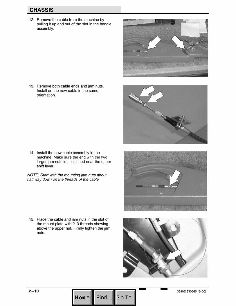
12. Remove the cable from the machine bypulling it up and out of the slot in the handleassembly.
13. Remove both cable ends and jam nuts.Install on the new cable in the sameorientation.
14. Install the new cable assembly in themachine. Make sure the end with the twolarger jam nuts is positioned near the uppershift lever.
NOTE: Start with the mounting jam nuts abouthalf way down on the threads of the cable.
15. Place the cable and jam nuts in the slot ofthe mount plate with 2--3 threads showingabove the upper nut. Firmly tighten the jamnuts.
CHASSIS
2--113640E 330565 (5--00)
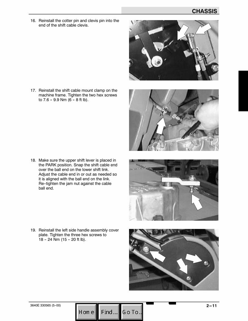
16. Reinstall the cotter pin and clevis pin into theend of the shift cable clevis.
17. Reinstall the shift cable mount clamp on themachine frame. Tighten the two hex screwsto 7.6 -- 9.9 Nm (6 -- 8 ft lb).
18. Make sure the upper shift lever is placed inthe PARK position. Snap the shift cable endover the ball end on the lower shift link.Adjust the cable end in or out as needed soit is aligned with the ball end on the link.Re--tighten the jam nut against the cableball end.
19. Reinstall the left side handle assembly coverplate. Tighten the three hex screws to18 -- 24 Nm (15 -- 20 ft lb).
CHASSIS
2--12 3640E 330565 (5--00)
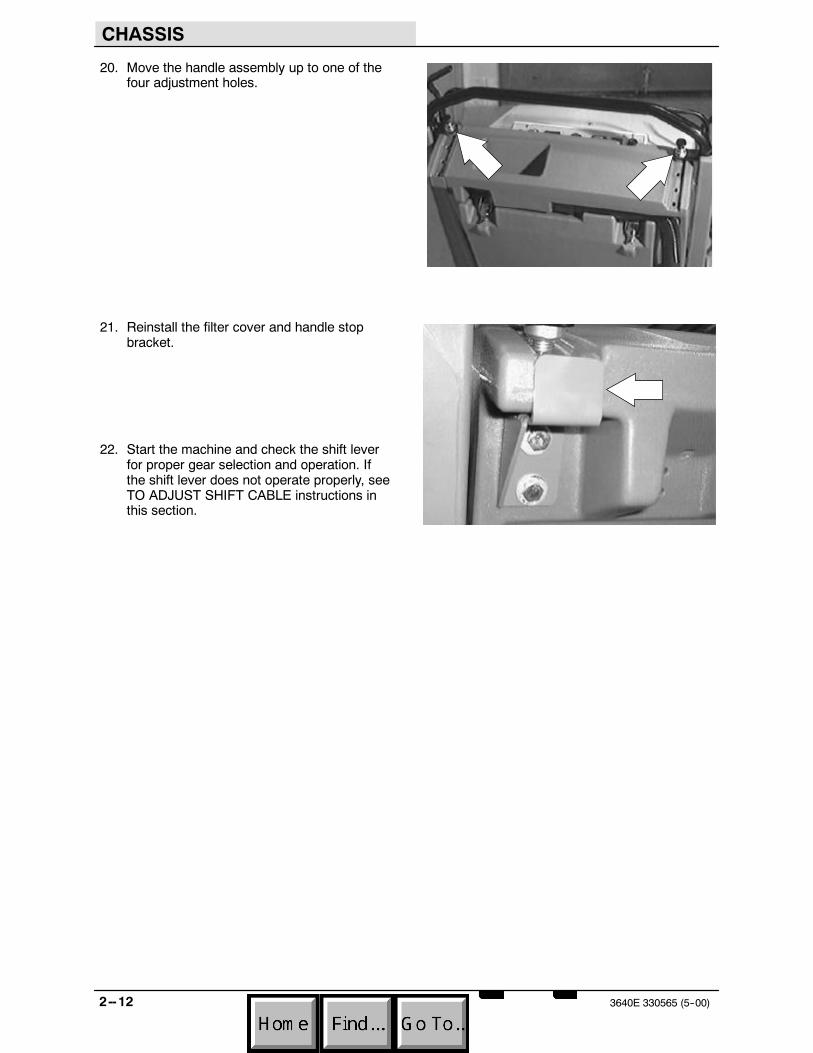
20. Move the handle assembly up to one of thefour adjustment holes.
21. Reinstall the filter cover and handle stopbracket.
22. Start the machine and check the shift leverfor proper gear selection and operation. Ifthe shift lever does not operate properly, seeTO ADJUST SHIFT CABLE instructions inthis section.

CHASSIS
2--133640E 330565 (5--00)
TO ADJUST SHIFT CABLE
FOR SAFETY: Before Leaving Or ServicingMachine; Stop On Level Surface, Place ShifterIn Park.
1. Pull the upper shift lever back until it is firmlyin the park position hole.
2. Go down to the shift link on the left side ofthe transaxle. Pop the cable end off the ballend on the link.
3. Once the cable end is off the ball end, verifythat the shift link is in the PARK detent.
CHASSIS
2--14 3640E 330565 (5--00)
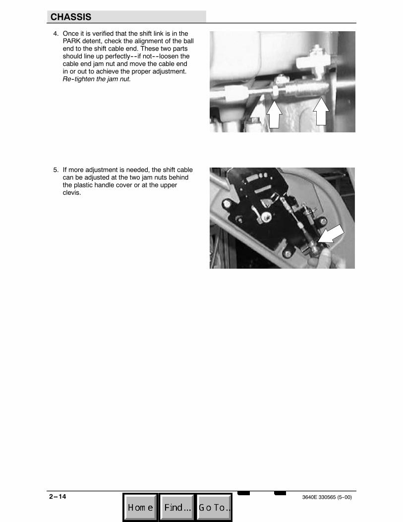
4. Once it is verified that the shift link is in thePARK detent, check the alignment of the ballend to the shift cable end. These two partsshould line up perfectly----if not----loosen thecable end jam nut and move the cable endin or out to achieve the proper adjustment.Re--tighten the jam nut.
5. If more adjustment is needed, the shift cablecan be adjusted at the two jam nuts behindthe plastic handle cover or at the upperclevis.

CHASSIS
2--153640E 330565 (5--00)
TRANSAXLE/TRANSMISSION
The 3640 is equipped with a transaxletransmission assembly. The transmission hasthree forward speeds, neutral, reverse, and park.The shift lever is on the left hand side of themachine, near the grip handle. The transmissioncan be shifted quickly between forward, neutral,and reverse by pushing or pulling the shift lever.
TO REMOVE TRANSAXLE
FOR SAFETY: Before Leaving Or ServicingMachine; Stop On Level Surface, Place ShifterIn Park.
1. Lift the rear of the machine until the drivewheels are off the floor.
2. Place blocks under the machine frame.
3. Remove the rear cover from the drive belt.
4. Slip the main drive belt off the sheave on thetransaxle.

CHASSIS
2--16 3640E 330565 (5--00)
5. Remove the flat head screw holding eachhub cap to the drive wheels.
6. Pull the hub cap and drive wheel off eachside of the machine.
7. Remove the hex screw, sleeve, and nutholding the left side of the brush shaft to theleft side of the brush arm.
8. Remove the two hex screws holding the shiftcable mount clamp to the machine frame.
CHASSIS
2--173640E 330565 (5--00)
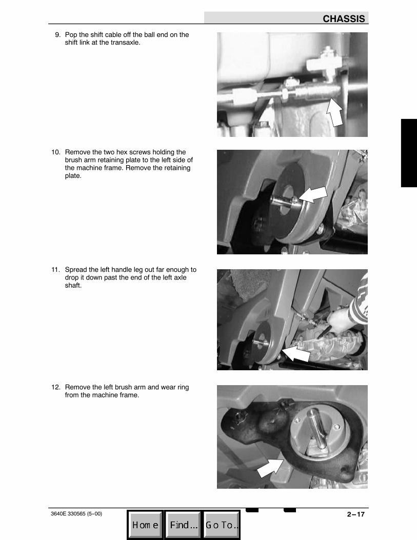
9. Pop the shift cable off the ball end on theshift link at the transaxle.
10. Remove the two hex screws holding thebrush arm retaining plate to the left side ofthe machine frame. Remove the retainingplate.
11. Spread the left handle leg out far enough todrop it down past the end of the left axleshaft.
12. Remove the left brush arm and wear ringfrom the machine frame.
CHASSIS
2--18 3640E 330565 (5--00)
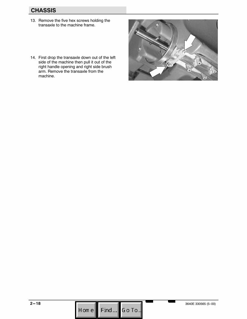
13. Remove the five hex screws holding thetransaxle to the machine frame.
14. First drop the transaxle down out of the leftside of the machine then pull it out of theright handle opening and right side brusharm. Remove the transaxle from themachine.

CHASSIS
2--193640E 330565 (5--00)
TO INSTALL TRANSAXLE
FOR SAFETY: Before Leaving Or ServicingMachine; Stop On Level Surface, Place ShifterIn Park.
1. Position the transaxle in the machine. First,place the right side of the transaxle throughthe right handle opening and right brusharm, then, bring the left side of the transaxleup to the left side of the machine frame.Reinstall the wear ring.
2. Install the five hex screws that hold thetransaxle to the bottom of the machineframe. Tighten to 7.6 -- 9.9 Nm (6 -- 8 ft lb).
NOTE: Install 3 flat washers under the transaxlewhere the 30mm hex screw goes.
3. Position the left brush arm over the end ofthe left axle shaft.
CHASSIS
2--20 3640E 330565 (5--00)
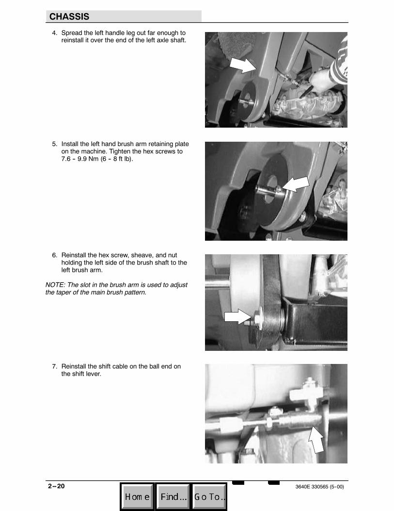
4. Spread the left handle leg out far enough toreinstall it over the end of the left axle shaft.
5. Install the left hand brush arm retaining plateon the machine. Tighten the hex screws to7.6 -- 9.9 Nm (6 -- 8 ft lb).
6. Reinstall the hex screw, sheave, and nutholding the left side of the brush shaft to theleft brush arm.
NOTE: The slot in the brush arm is used to adjustthe taper of the main brush pattern.
7. Reinstall the shift cable on the ball end onthe shift lever.

CHASSIS
2--213640E 330565 (5--00)
8. Reinstall the two hex screws holding theshift cable mount clamp to the machineframe. Tighten to 7.6 -- 9.9 Nm (6 -- 8 ft lb).
9. Reinstall the main drive belt on the transaxlesheave.
10. Reinstall the rear belt cover on the machine.
11. Reinstall the rear drive wheels and hubcaps. Tighten the flat head screw to7.6 -- 9.9 Nm (6 -- 8 ft lb).
NOTE: Place machine in Neutral and rotate axleuntil cross pin is horizontal. Put machine in Park.Install hub/wheel assembly.
12. Remove the blocks and lower the machine.Check for proper operation of the shifter andtransaxle. Also check the main brush patternand adjust if tapered. See TO CHECK ANDADJUST MAIN BRUSH PATTERNinstructions in the SWEEPING section.

TRANSAXLEBREAKDOWN
CHASSIS
2--22 3640E 330565 (5--00)

CHASSIS
2--233640E 330565 (5--00)
TO REPLACE FLAT DRIVE BELT
FOR SAFETY: Before Leaving Or ServicingMachine; Stop On Level Surface, Place ShifterIn Park.
1. Open the cover and engage the prop rod.
2. Remove the rear cover from the drive belt atthe transaxle sheave.
3. Loosen the vacuum fan pivot bolt andremove the vacuum fan belt from the motorsheave.
CHASSIS
2--24 3640E 330565 (5--00)
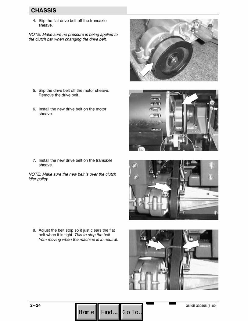
4. Slip the flat drive belt off the transaxlesheave.
NOTE: Make sure no pressure is being applied tothe clutch bar when changing the drive belt.
5. Slip the drive belt off the motor sheave.Remove the drive belt.
6. Install the new drive belt on the motorsheave.
7. Install the new drive belt on the transaxlesheave.
NOTE: Make sure the new belt is over the clutchidler pulley.
8. Adjust the belt stop so it just clears the flatbelt when it is tight. This to stop the beltfrom moving when the machine is in neutral.

CHASSIS
2--253640E 330565 (5--00)
9. Reinstall the vacuum fan belt.
10. Pull up on the vacuum fan assembly untilthe V--belt is tight. Check belt tension byapplying a force 1 kg (2 lb) at belt midpoint.The proper deflection should be 5 mm(0.09 in).Tighten the tension bolt to18 -- 24 Nm (15 -- 20 ft lb).
11. Reinstall the rear belt cover on the machine.
12. Start the machine and operate the clutchbar. Check for proper engagement of thenew belt and smooth operation.
CHASSIS
2--26 3640E 330565 (5--00)
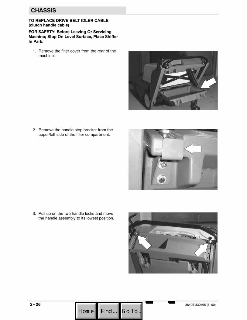
TO REPLACE DRIVE BELT IDLER CABLE(clutch handle cable)
FOR SAFETY: Before Leaving Or ServicingMachine; Stop On Level Surface, Place ShifterIn Park.
1. Remove the filter cover from the rear of themachine.
2. Remove the handle stop bracket from theupper/left side of the filter compartment.
3. Pull up on the two handle locks and movethe handle assembly to its lowest position.

CHASSIS
2--273640E 330565 (5--00)
4. Remove the three hex screws holding thecover plate to the inside of the left sidehandle tower. Remove the cover plate fromthe machine.
5. Open the motor cover and engage the proprod.
6. Go to the area below the vacuum fan andlocate the tension spring leading from theidler pulley arm to the end of the drive beltidler cable. Disconnect the spring from thecable.
7. Loosen the two jam nuts on the cable whereit mounts to the bracket near the shakermotor. Slip the cable out of the mount slot.
CHASSIS
2--28 3640E 330565 (5--00)
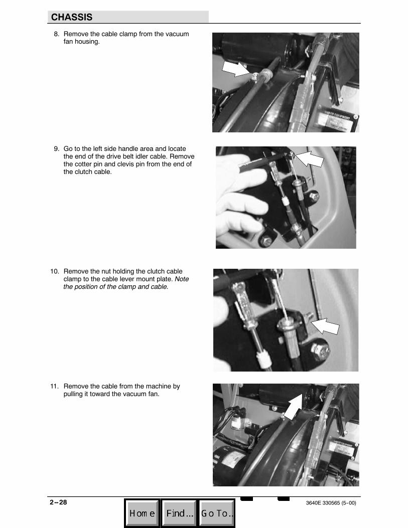
8. Remove the cable clamp from the vacuumfan housing.
9. Go to the left side handle area and locatethe end of the drive belt idler cable. Removethe cotter pin and clevis pin from the end ofthe clutch cable.
10. Remove the nut holding the clutch cableclamp to the cable lever mount plate. Notethe position of the clamp and cable.
11. Remove the cable from the machine bypulling it toward the vacuum fan.
CHASSIS
2--293640E 330565 (5--00)
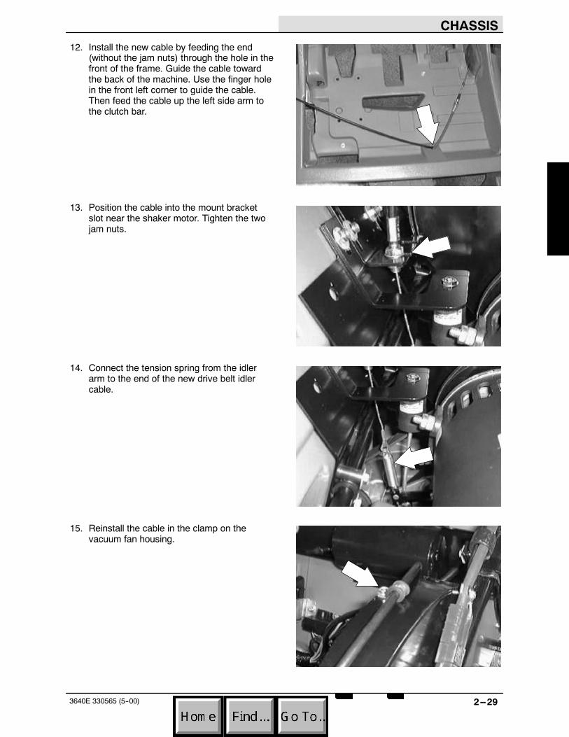
12. Install the new cable by feeding the end(without the jam nuts) through the hole in thefront of the frame. Guide the cable towardthe back of the machine. Use the finger holein the front left corner to guide the cable.Then feed the cable up the left side arm tothe clutch bar.
13. Position the cable into the mount bracketslot near the shaker motor. Tighten the twojam nuts.
14. Connect the tension spring from the idlerarm to the end of the new drive belt idlercable.
15. Reinstall the cable in the clamp on thevacuum fan housing.

CHASSIS
2--30 3640E 330565 (5--00)
16. Reinstall the clamp and nut onto the newcable in the handle area. Tighten to7.6 -- 9.9 Nm (6 -- 8 ft lb).
17. Reinstall the clevis pin and cotter pin in theend of the new cable and clutch bar.
18. Reinstall the left side cover plate. Tightenthe three hex screws to 18 -- 24 Nm(15 -- 20 ft lb).
19. Move the handle assembly up to one of thefour adjustment holes.

CHASSIS
2--313640E 330565 (5--00)
20. Reinstall the the handle stop bracket.
21. Reinstall the filter cover onto the rear of themachine.
22. Close the motor cover.
23. Start the machine and check the clutch barfor proper engagement. If the new cableneeds to be adjusted, open the motor coverand loosen the two idler cable jam nuts.Move the cable or cable bracket up or downand re--tighten the jam nuts. Close the coverand re--check.
CHASSIS
2--32 3640E 330565 (5--00)
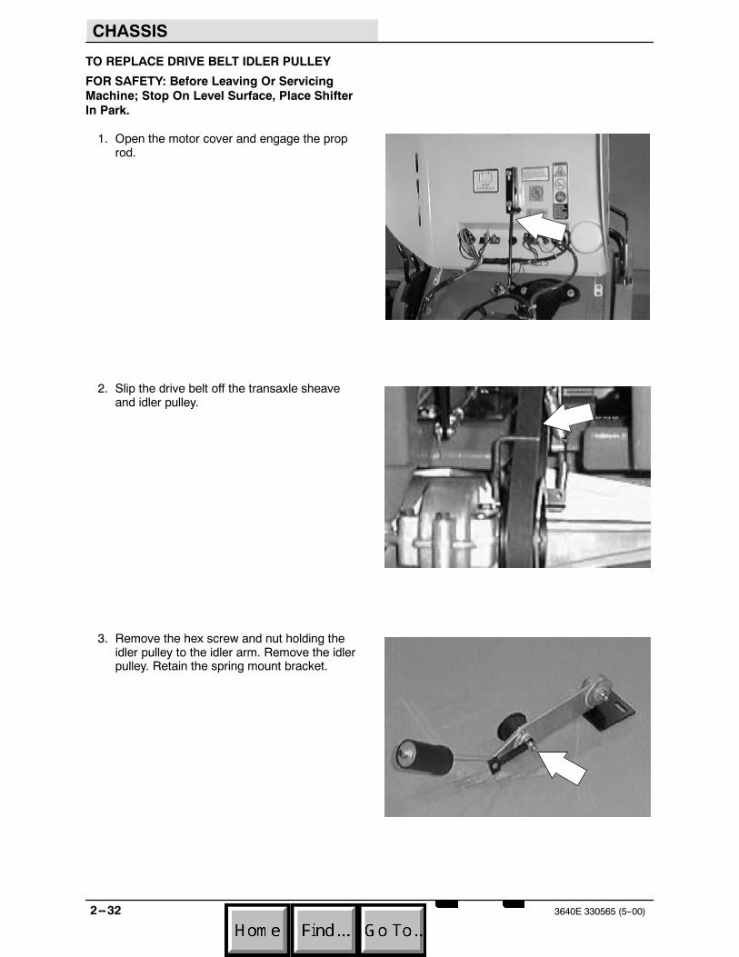
TO REPLACE DRIVE BELT IDLER PULLEY
FOR SAFETY: Before Leaving Or ServicingMachine; Stop On Level Surface, Place ShifterIn Park.
1. Open the motor cover and engage the proprod.
2. Slip the drive belt off the transaxle sheaveand idler pulley.
3. Remove the hex screw and nut holding theidler pulley to the idler arm. Remove the idlerpulley. Retain the spring mount bracket.

CHASSIS
2--333640E 330565 (5--00)
4. Install the new idler pulley on the idler arm.Make sure to reinstall the spring mountbracket. Tighten the hex screw and nut to7.6 -- 9.9 Nm (6 -- 8 ft lb).
5. Slip the drive belt back over the transaxlesheave and the new idler pulley.
6. Lower the motor cover and operate themachine. Check the new idler for properoperation.

CHASSIS
2--34 3640E 330565 (5--00)

SWEEPING
3--13640E 330565 (5--00)
CONTENTS
Page
INTRODUCTION 3--3. . . . . . . . . . . . . . . . . . . . . .DEBRIS HOPPER 3--4. . . . . . . . . . . . . . . . . . . . .
TO REMOVE DEBRIS HOPPER 3--4. . . . .TO INSTALL DEBRIS HOPPER 3--5. . . . . .
OPTIONS 3--6. . . . . . . . . . . . . . . . . . . . . . . . . . . .HOPPER DUMP ASSIST HANDLE 3--6. . .
THERMO SENTRYt 3--7. . . . . . . . . . . . . . . . . .TO REPLACE THERMO SENTRYt 3--7. .
VACUUM WAND 3--8. . . . . . . . . . . . . . . . . . . . . .HOPPER DUST FILTER 3--9. . . . . . . . . . . . . . .
TO REPLACE FILTER BAG (standard)3--10TO REPLACE PANEL DUST
FILTER (optional) 3--12. . . . . . . . . . . . . . .MAIN BRUSH 3--14. . . . . . . . . . . . . . . . . . . . . . .
TO REPLACE MAIN BRUSH 3--14. . . . . . .TO CHECK AND ADJUST MAIN
BRUSH PATTERN 3--17. . . . . . . . . . . . . .TO REPLACE MAIN BRUSH LIFT
CABLE 3--18. . . . . . . . . . . . . . . . . . . . . . . .TO REPLACE MAIN BRUSH DRIVE
BELT 3--24. . . . . . . . . . . . . . . . . . . . . . . . .TO REPLACE MAIN BRUSH DRIVE
BELT IDLER BEARINGS 3--27. . . . . . . .TO REPLACE MAIN BRUSH DRIVE
SHEAVE 3--31. . . . . . . . . . . . . . . . . . . . . .TO REPLACE STAINLESS STEEL
BRUSH ARM WEAR RINGS 3--35. . . .TO REMOVE MAIN BRUSH SHAFT 3--39.TO INSTALL MAIN BRUSH SHAFT 3--41. .
SIDE BRUSH 3--42. . . . . . . . . . . . . . . . . . . . . . . .TO REPLACE LH OR RH SIDE
BRUSH 3--42. . . . . . . . . . . . . . . . . . . . . . .TO REPLACE SIDE BRUSH LIFT
CABLE 3--44. . . . . . . . . . . . . . . . . . . . . . . .TO REPLACE SIDE BRUSH
HOUSING 3--50. . . . . . . . . . . . . . . . . . . . .
Page
SKIRTS AND SEALS 3--54. . . . . . . . . . . . . . . . .HOPPER LIP SKIRT 3--54. . . . . . . . . . . . . . . . . .
TO REPLACE HOPPER LIP SKIRT 3--54. .REAR SKIRT 3--56. . . . . . . . . . . . . . . . . . . . . . . .
TO REPLACE REAR SKIRT/RECIRCULATION FLAP 3--56. . . . . . . . .
UPPER HOPPER SEAL 3--58. . . . . . . . . . . . . .TO REPLACE UPPER HOPPER
SEAL 3--58. . . . . . . . . . . . . . . . . . . . . . . . .MAIN BRUSH DUST SEALS 3--60. . . . . . . . . .
TO REPLACE LEFT BRUSH SEAL(idler side) 3--60. . . . . . . . . . . . . . . . . . . . .
TO REPLACE RIGHT BRUSH SEAL(drive belt side) 3--63. . . . . . . . . . . . . . . . .
VACUUM FAN 3--66. . . . . . . . . . . . . . . . . . . . . . .TO REMOVE VACUUM FAN
ASSEMBLY 3--66. . . . . . . . . . . . . . . . . . . .TO INSTALL VACUUM FAN
ASSEMBLY 3--68. . . . . . . . . . . . . . . . . . . .TO REPLACE VACUUM FAN
IMPELLER 3--71. . . . . . . . . . . . . . . . . . . .TO REPLACE VACUUM FAN
IMPELLER BEARINGS 3--73. . . . . . . . . .TO TENSION VACUUM FAN V--BELT 3--77
MACHINE TROUBLESHOOTING 3--79. . . . . .

SWEEPING
3--2 3640E 330565 (5--00)
SWEEPING
3--33640E 330565 (5--00)
INTRODUCTION
This section includes information on the sweepingoperation. The side brush sweeps debris in frontof the machine and the main brush sweeps thedebris into the hopper. The vacuum fan pulls airfrom the hopper and through the dust filter.
SWEEPING
3--4 3640E 330565 (5--00)
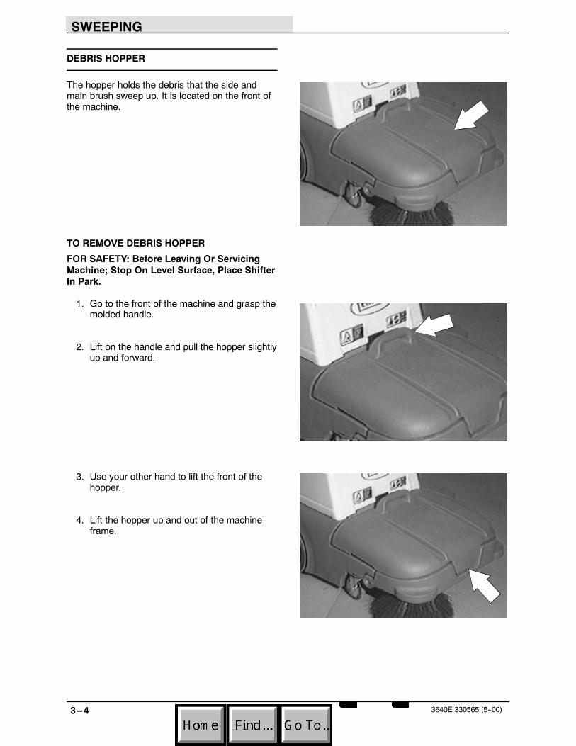
DEBRIS HOPPER
The hopper holds the debris that the side andmain brush sweep up. It is located on the front ofthe machine.
TO REMOVE DEBRIS HOPPER
FOR SAFETY: Before Leaving Or ServicingMachine; Stop On Level Surface, Place ShifterIn Park.
1. Go to the front of the machine and grasp themolded handle.
2. Lift on the handle and pull the hopper slightlyup and forward.
3. Use your other hand to lift the front of thehopper.
4. Lift the hopper up and out of the machineframe.

SWEEPING
3--53640E 330565 (5--00)
TO INSTALL DEBRIS HOPPER
FOR SAFETY: Before Leaving Or ServicingMachine; Stop On Level Surface, Place ShifterIn Park.
1. Position the hopper in the machine with theopen end facing the main brush.
2. Let the hopper rest on the machine frontframe rails.
3. Push the hopper back until the two frameknobs are lined up with the two indentationsin the hopper. The hopper is now in itscorrect position.

SWEEPING
3--6 3640E 330565 (5--00)
OPTIONS
HOPPER DUMP ASSIST HANDLE
The dump assist handle allows easy removal andtransport of the debris hopper when it is full.
Raise the dump assist handle.
Place one foot on the hopper’s pivot point.
Lift the hooper out of the machine and onto thewheels. Transport the hopper to the locationwhere debris is contained.
NOTE: Do not attempt to lift the hopper when it isfull of debris. Dump the debris from the hopperinto a pile on the floor near a trash can ordumpster, then pick the debris up with a shovel.
SWEEPING
3--73640E 330565 (5--00)
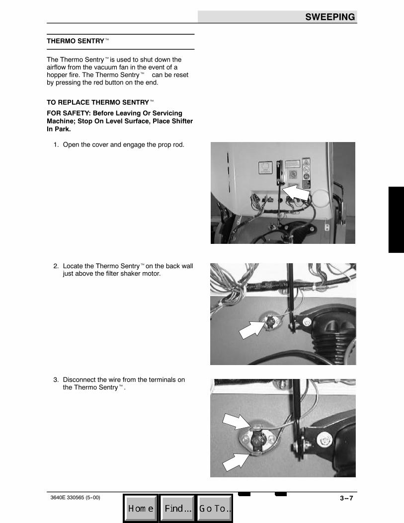
THERMO SENTRYt
The Thermo Sentrytis used to shut down theairflow from the vacuum fan in the event of ahopper fire. The Thermo Sentryt can be resetby pressing the red button on the end.
TO REPLACE THERMO SENTRYt
FOR SAFETY: Before Leaving Or ServicingMachine; Stop On Level Surface, Place ShifterIn Park.
1. Open the cover and engage the prop rod.
2. Locate the Thermo Sentryton the back walljust above the filter shaker motor.
3. Disconnect the wire from the terminals onthe Thermo Sentryt.

SWEEPING
3--8 3640E 330565 (5--00)
4. Remove the two self threading hex screwsholding the Thermo Sentryt to the panel.Remove the Thermo Sentryt.
5. Position the new Thermo Sentryt on thepanel. Reinstall the hardware and lightlyhand tighten.
6. Reconnect the wires to the ThermoSentryt. See schematic in theELECTRICAL section.
7. Close the cover.
VACUUM WAND
The vacuum wand uses the machine’s vacuumsystem. Use the vacuum wand to pick up debris innarrow or partially enclosed areas that cannot beswept by the machine.
NOTE: The vacuum hose screws into the vacuumnozzle (left hand thread). Un--screw to replace thehose.

SWEEPING
3--93640E 330565 (5--00)
HOPPER DUST FILTER
The hopper filter is located at the rear of themachine, behind the rear cover.
The standard filter is a bag style that is simplyremoved and discarded when full.
The optional filter is a panel style that can becleaned and re--used multiple times. The optionalfilter also comes with a filter shaker system thatcan be used to shake the filter between cleanings.
Bag filter
Panel filter
SWEEPING
3--10 3640E 330565 (5--00)
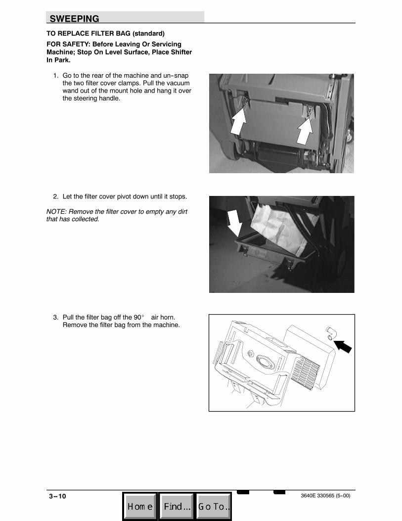
TO REPLACE FILTER BAG (standard)
FOR SAFETY: Before Leaving Or ServicingMachine; Stop On Level Surface, Place ShifterIn Park.
1. Go to the rear of the machine and un--snapthe two filter cover clamps. Pull the vacuumwand out of the mount hole and hang it overthe steering handle.
2. Let the filter cover pivot down until it stops.
NOTE: Remove the filter cover to empty any dirtthat has collected.
3. Pull the filter bag off the 90_ air horn.Remove the filter bag from the machine.

SWEEPING
3--113640E 330565 (5--00)
4. Position the new filter bag in the filter area.Place the hole in the bag over the end of the90_ air horn.
5. Pivot the filter cover into position. Make surethe upper portion of the vacuum wand hoseis in the proper location.
6. Reconnect the two filter clamps and snapthem into the lock position. Reinstall thevacuum wand in the mount hole.
7. Start the machine and check the hopperfilter area for any air leaks.

SWEEPING
3--12 3640E 330565 (5--00)
TO REPLACE PANEL DUST FILTER (optional)
FOR SAFETY: Before Leaving Or ServicingMachine; Stop On Level Surface, Place ShifterIn Park.
1. Go to the rear of the machine and un--snapthe two filter cover clamps. Pull the vacuumwand out of the mount hole and hang it overthe steering handle.
2. Let the filter cover pivot down until it stops.
NOTE: Remove the filter cover to empty any dirtthat has collected.
3. Un--snap the catch lock on the filter lockbars.

SWEEPING
3--133640E 330565 (5--00)
4. Pivot the two filter lock bars back.
5. Remove the old filter by grasping the tabson both sides and pulling out. Pull the oldfilter down and out of the filter compartment.
6. Position the new filter in the filter carrier.Make sure the air flow arrows point intoward the battery compartment.
7. Pivot the filter lock bars over the new filterand reconnect the catch lock.
8. Rotate the filter cover back into place. Makesure the upper portion of the vacuum wandhose is in the proper location.
9. Reconnect the two filter clamps and snapthem into the lock position. Reinstall thevacuum wand in the mount hole.
10. Start the machine and check the hopperfilter area for any air leaks.

SWEEPING
3--14 3640E 330565 (5--00)
MAIN BRUSH
The main brush is used to throw the debris intothe hopper. The main brush can be rotated endfor end to extend the life of the bristles.
TO REPLACE MAIN BRUSH
FOR SAFETY: Before Leaving Or ServicingMachine; Stop On Level Surface, Place ShifterIn Park.
1. Remove the debris hopper from the machineand drop the main brush to the full floatposition.
2. Go to the left side of the machine and locatethe main brush idler side knob pin. This pinis located in the brush arm, just ahead ofthe LH drive wheel.

SWEEPING
3--153640E 330565 (5--00)
3. Push in on the knob pin and turn at thesame time. Remove the pin from the brusharm.
4. Remove the main brush from the machineby pulling the left side of the brush forward,then, pull the brush off the drive plug on theright side.
5. After the main brush has been removedfrom the machine, remove the bearingassembly from the idler side end of thebrush.
6. Install the bearing assembly in either end ofthe new brush.
SWEEPING
3--16 3640E 330565 (5--00)
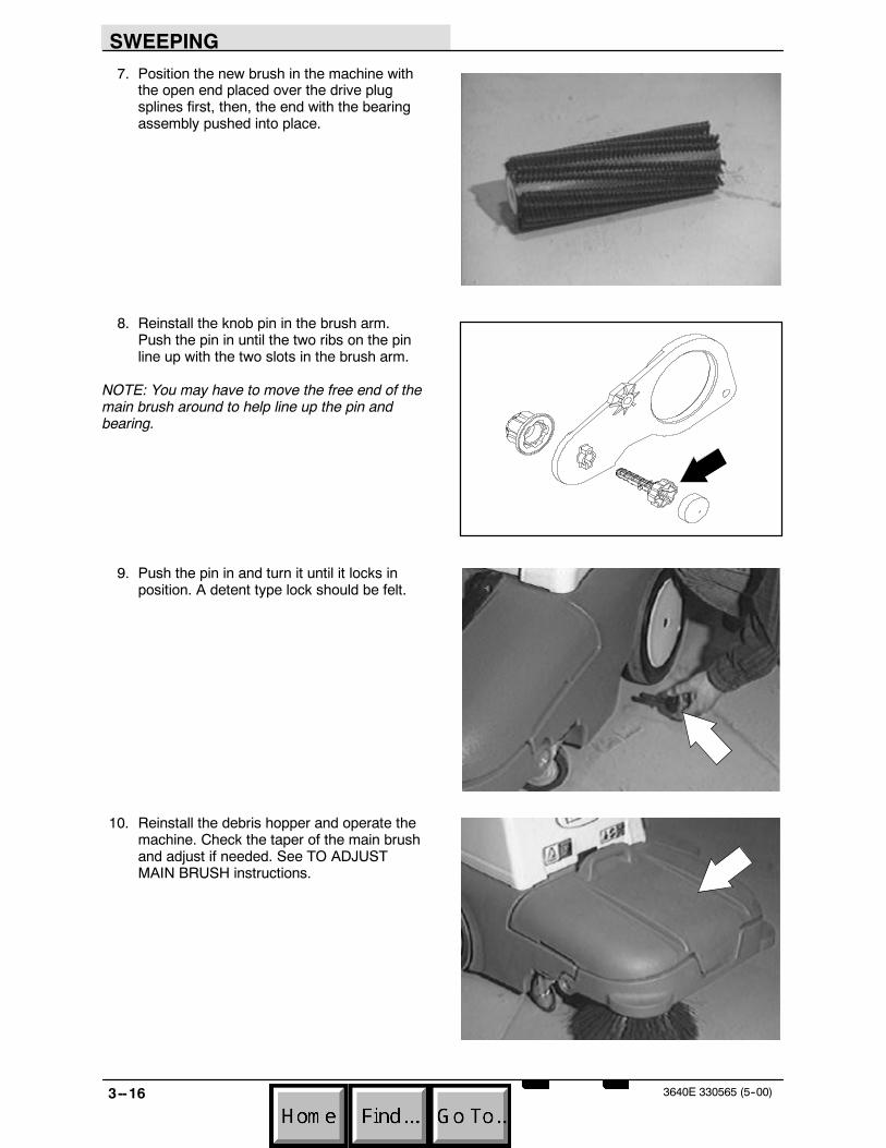
7. Position the new brush in the machine withthe open end placed over the drive plugsplines first, then, the end with the bearingassembly pushed into place.
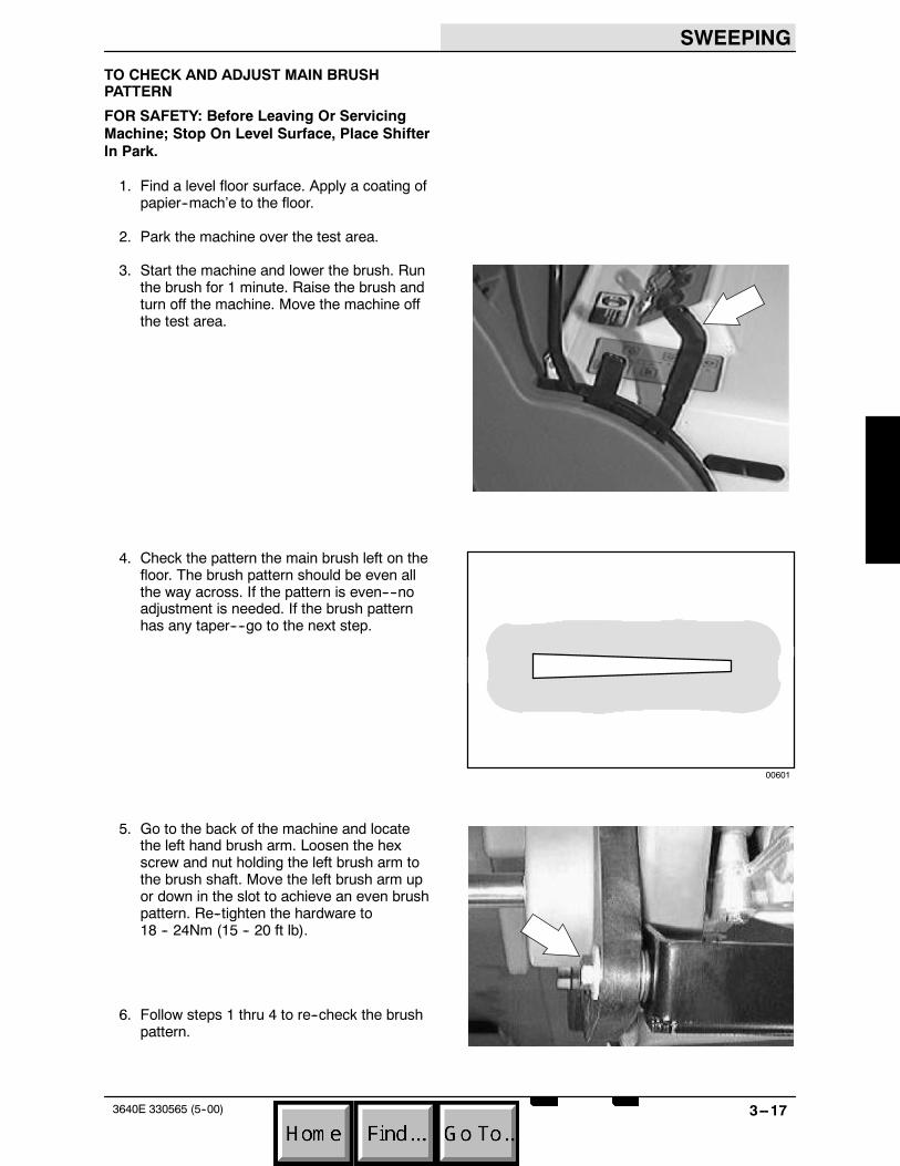
8. Reinstall the knob pin in the brush arm.Push the pin in until the two ribs on the pinline up with the two slots in the brush arm.
NOTE: You may have to move the free end of themain brush around to help line up the pin andbearing.
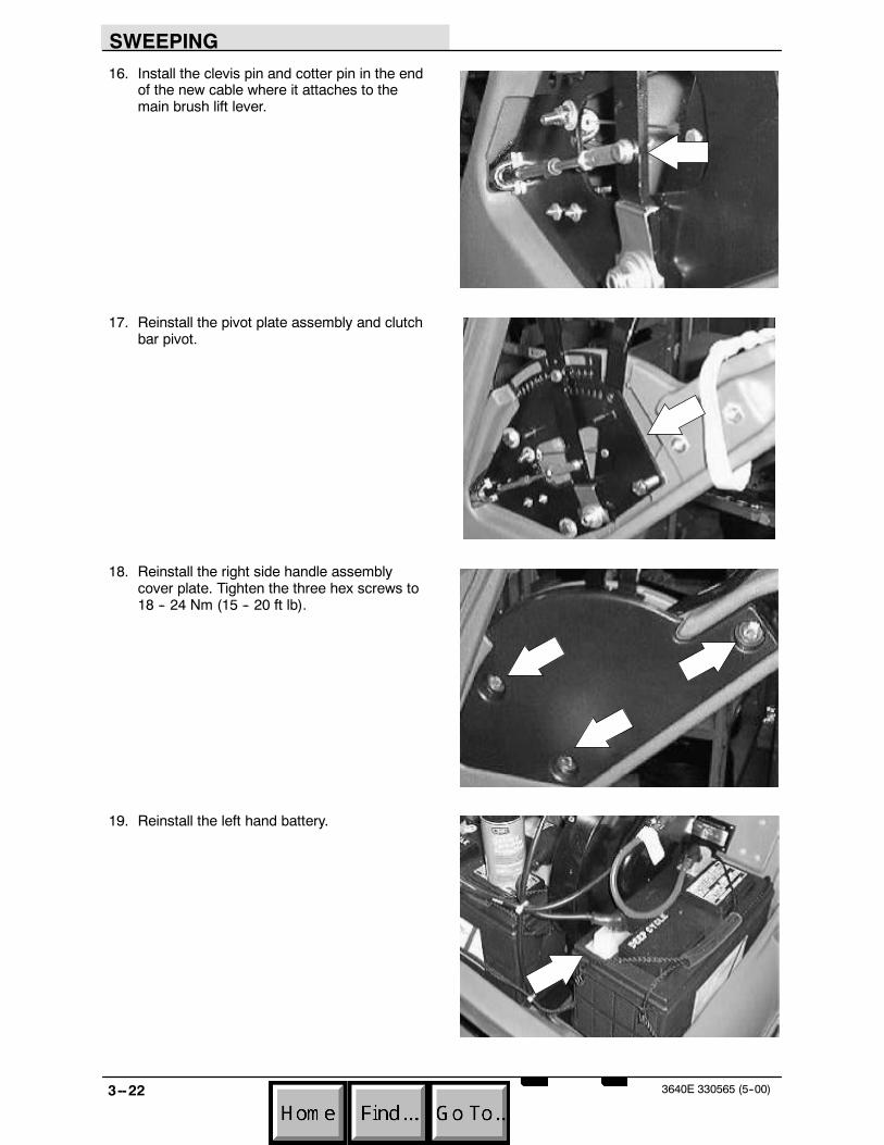
9. Push the pin in and turn it until it locks inposition. A detent type lock should be felt.
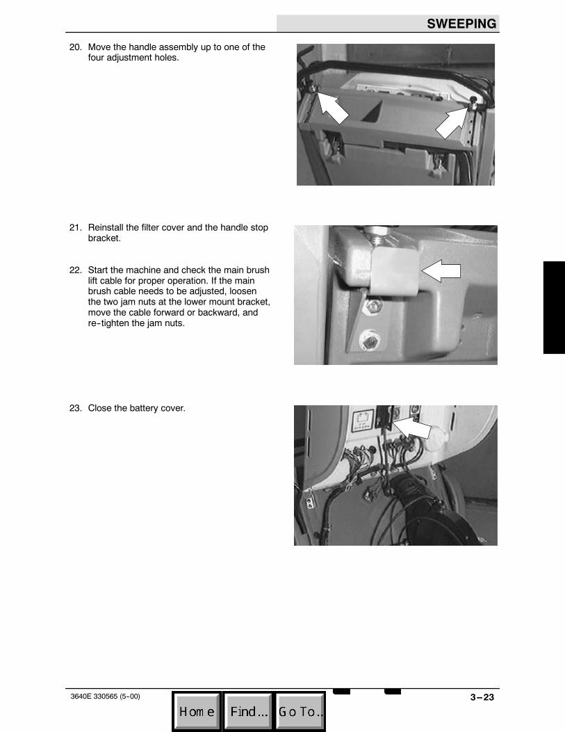
10. Reinstall the debris hopper and operate themachine. Check the taper of the main brushand adjust if needed. See TO ADJUSTMAIN BRUSH instructions.
SWEEPING
3--173640E 330565 (5--00)
TO CHECK AND ADJUST MAIN BRUSHPATTERN
FOR SAFETY: Before Leaving Or ServicingMachine; Stop On Level Surface, Place ShifterIn Park.
1. Find a level floor surface. Apply a coating ofpapier--mach’e to the floor.
2. Park the machine over the test area.
3. Start the machine and lower the brush. Runthe brush for 1 minute. Raise the brush andturn off the machine. Move the machine offthe test area.
4. Check the pattern the main brush left on thefloor. The brush pattern should be even allthe way across. If the pattern is even----noadjustment is needed. If the brush patternhas any taper----go to the next step.
5. Go to the back of the machine and locatethe left hand brush arm. Loosen the hexscrew and nut holding the left brush arm tothe brush shaft. Move the left brush arm upor down in the slot to achieve an even brushpattern. Re--tighten the hardware to18 -- 24Nm (15 -- 20 ft lb).
6. Follow steps 1 thru 4 to re--check the brushpattern.
00601

SWEEPING
3--18 3640E 330565 (5--00)
TO REPLACE MAIN BRUSH LIFT CABLE
FOR SAFETY: Before Leaving Or ServicingMachine; Stop On Level Surface, Place ShifterIn Park.
1. Remove the filter cover from the rear of themachine. Remove the handle stop bracketfrom the upper/left side of the filtercompartment.
2. Pull up on the two handle locks and movethe handle assembly to its lowest position.
3. Remove the three hex screws holding thecover plate to the inside of the right sidehandle tower. Remove the cover plate fromthe machine.

SWEEPING
3--193640E 330565 (5--00)
4. Remove the bolt and sleeve that holds theclutch bar to the plastic side arm. This willallow the pivot plate and handle assembly totip out for better access.
5. Remove the cotter pin and clevis pin fromthe end of the main brush lift cable where itattaches to the main brush lift lever.
6. Remove the nut from the clamp holding themain brush cable to the mount plate.
7. Open the battery cover and remove the lefthand battery. Locate the end of the mainbrush lift cable where it attaches to themount bracket below the vacuum fan.Remove the cotter pin and clevis pin fromthe lift cable and brush lift arm.

SWEEPING
3--20 3640E 330565 (5--00)
8. Loosen the two jam nuts on the lift cablewhere it attaches to the mount bracket. Slipthe lift cable out of the mount slot.
9. Remove the cotter pin and clevis pin wherethe main brush lift cable attaches to thebrush lift weldment.
10. Pull the old main brush lift cable out of themachine from the lower end by the vacuumfan.
11. Route the new lift cable through the hole inthe front, center of the frame. Push thecable toward the front, right corner. Next,reach into the corner finger hole to guide thecable to the rear of the machine frame andup into the side arm and the lift handle.
NOTE: Add a cable tie around the new mainbrush lift cable and the existing side brush liftcable. This will prevent the side brush lift cablefrom drooping down and rubbing on the brushdrive pulley.

SWEEPING
3--213640E 330565 (5--00)
12. Remove the clevis and jam nut from bothends of the old cable and install on the newlift cable in the same position andorientation.
13. Position the new cable in the lower mountslot and tighten the jam nuts.
14. Install the clevis pin and cotter pin in the endof the new cable where it attaches to themain brush lift arm.
15. Go up to the main brush lift lever and installthe nut on the main brush lift cable mountclamp. Tighten the nut to 7.6 -- 9.9 Nm(6 -- 8 ft lb).
SWEEPING
3--22 3640E 330565 (5--00)
16. Install the clevis pin and cotter pin in the endof the new cable where it attaches to themain brush lift lever.
17. Reinstall the pivot plate assembly and clutchbar pivot.
18. Reinstall the right side handle assemblycover plate. Tighten the three hex screws to18 -- 24 Nm (15 -- 20 ft lb).
19. Reinstall the left hand battery.
SWEEPING
3--233640E 330565 (5--00)
20. Move the handle assembly up to one of thefour adjustment holes.
21. Reinstall the filter cover and the handle stopbracket.
22. Start the machine and check the main brushlift cable for proper operation. If the mainbrush cable needs to be adjusted, loosenthe two jam nuts at the lower mount bracket,move the cable forward or backward, andre--tighten the jam nuts.
23. Close the battery cover.
SWEEPING
3--24 3640E 330565 (5--00)
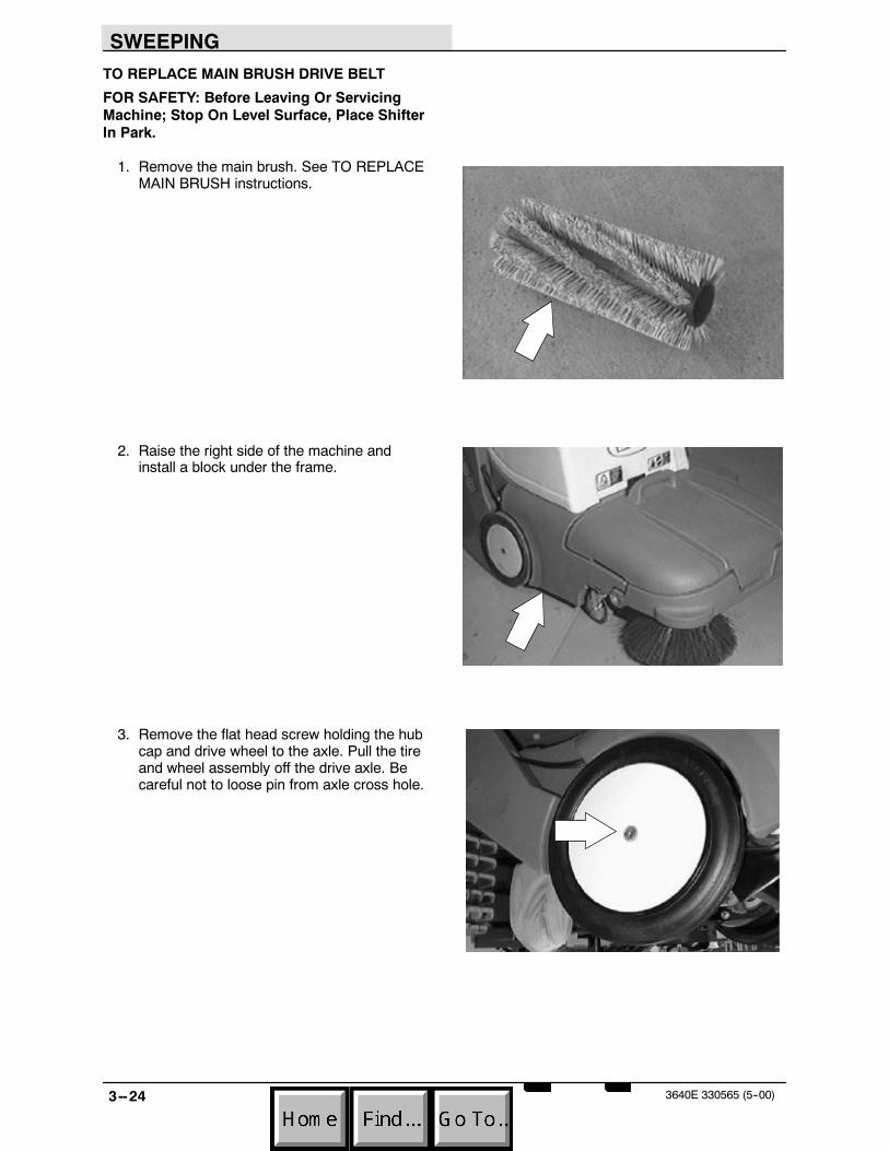
TO REPLACE MAIN BRUSH DRIVE BELT
FOR SAFETY: Before Leaving Or ServicingMachine; Stop On Level Surface, Place ShifterIn Park.
1. Remove the main brush. See TO REPLACEMAIN BRUSH instructions.
2. Raise the right side of the machine andinstall a block under the frame.
3. Remove the flat head screw holding the hubcap and drive wheel to the axle. Pull the tireand wheel assembly off the drive axle. Becareful not to loose pin from axle cross hole.

SWEEPING
3--253640E 330565 (5--00)
4. Place the main brush lift lever in the downposition. Remove the retainer plate coveringthe belt drive.
5. Place a screw driver in the 1/4 in. hole in thebrush arm behind the idler arm. Place themain brush lift lever in the up position.The screw driver will hold the idler frommoving and tension on the brush belt will bereleased.
NOTE: The pressure on the belt tensioner mustbe released before the drive belt can be replaced.
6. Remove the old brush belt from the motorsheave, belt tensioner sheaves, and mainbrush drive plug sheave. Remove the drivebelt from the machine.
7. Position the new drive belt in the machine.First, loop it over the motor sheave, then,over the main brush drive plug sheave, then,the idler sheaves.
Engine/motorsheave
Main brushdrive sheave
Idler pulleys
Front ofmachine
Flat belt

SWEEPING
3--26 3640E 330565 (5--00)
8. Place the main brush lift lever in the downposition.
9. Remove the screw driver from the brusharm. Place the main brush lift lever in the upposition. Reinstall the belt drive plate.
10. Reinstall the right side drive wheel and hubcap. Tighten the flat screw to 7.6 -- 9.9 Nm(6 -- 8 ft lb).
NOTE: Place machine in Neutral, then, rotate axleuntil cross pin is horizontal. Put machine in Parkand install hub/wheel assembly.
11. Install the main brush. See TO REPLACEMAIN BRUSH instructions. Lower themachine and operate the main brush. Checkfor proper operation.

SWEEPING
3--273640E 330565 (5--00)
TO REPLACE MAIN BRUSH DRIVE BELTIDLER BEARINGS
FOR SAFETY: Before Leaving Or ServicingMachine; Stop On Level Surface, Place ShifterIn Park.
1. Remove the main brush. See TO REPLACEMAIN BRUSH instructions.
2. Raise the right side of the machine andinstall a block under the frame.
3. Remove the flat head screw holding the hubcap and drive wheel to the axle. Pull the tireand wheel assembly off the drive axle. Becareful not to loose pin from axle cross hole.

SWEEPING
3--28 3640E 330565 (5--00)
4. Place the main brush lift lever in the downposition. Remove the retainer plate coveringthe belt drive.
5. Place a screw driver in the 1/4 in. hole in thebrush arm behind the idler arm. Place themain brush lift lever in the up position.The screw driver will hold the idler frommoving and tension on the brush belt will bereleased.
NOTE: The pressure on the belt tensioner mustbe released before the drive belt can be replaced.
6. Remove the old brush belt from the motorsheave, belt tensioner sheaves, and mainbrush drive plug sheave.
7. Remove the hex nut or hex screw holdingthe idler pulley to the idler arm. Remove theidler pulley from the machine.
SWEEPING
3--293640E 330565 (5--00)
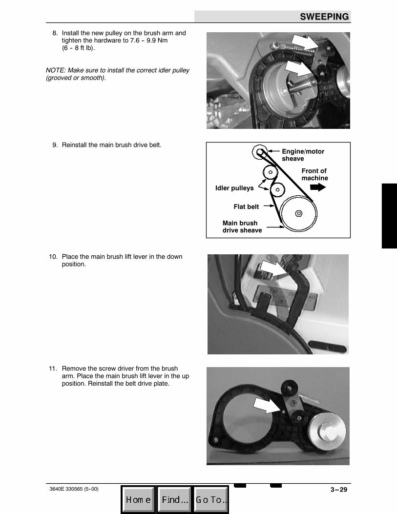
8. Install the new pulley on the brush arm andtighten the hardware to 7.6 -- 9.9 Nm(6 -- 8 ft lb).
NOTE: Make sure to install the correct idler pulley(grooved or smooth).
9. Reinstall the main brush drive belt.
10. Place the main brush lift lever in the downposition.
11. Remove the screw driver from the brusharm. Place the main brush lift lever in the upposition. Reinstall the belt drive plate.
Engine/motorsheave
Main brushdrive sheave
Idler pulleys
Front ofmachine
Flat belt
SWEEPING
3--30 3640E 330565 (5--00)
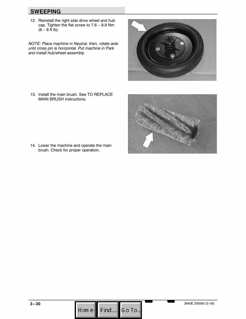
12. Reinstall the right side drive wheel and hubcap. Tighten the flat screw to 7.6 -- 9.9 Nm(6 -- 8 ft lb).
NOTE: Place machine in Neutral, then, rotate axleuntil cross pin is horizontal. Put machine in Parkand install hub/wheel assembly.
13. Install the main brush. See TO REPLACEMAIN BRUSH instructions.
14. Lower the machine and operate the mainbrush. Check for proper operation.

SWEEPING
3--313640E 330565 (5--00)
TO REPLACE MAIN BRUSH DRIVE SHEAVE
FOR SAFETY: Before Leaving Or ServicingMachine; Stop On Level Surface, Place ShifterIn Park.
1. Remove the main brush. See TO REPLACEMAIN BRUSH instructions.
2. Raise the right side of the machine andinstall a block under the frame.
3. Remove the flat head screw holding the hubcap and drive wheel to the axle. Pull the tireand wheel assembly off the drive axle. Becareful not to loose pin from axle cross hole.

SWEEPING
3--32 3640E 330565 (5--00)
4. Place the main brush lift lever in the downposition. Remove the retainer plate coveringthe belt drive.
5. Place a screw driver in the 1/4 in. hole in thebrush arm behind the idler arm. Place themain brush lift lever in the up position.The screw driver will hold the idler frommoving and tension on the brush belt will bereleased.
NOTE: The pressure on the belt tensioner mustbe released before the drive belt can be replaced.
6. Remove the brush belt from the motorsheave, belt tensioner sheaves, and mainbrush drive plug sheave.
7. Remove the screw holding the brush driveplug to the pulley shaft. Remove the driveplug and square key.

SWEEPING
3--333640E 330565 (5--00)
8. Press the sheave and shaft out of the brusharm.
9. Press the new sheave and shaft into thebrush arm.
10. Reinstall the square key and drive plug onthe shaft. Reinstall the screw and tighten to7.6 -- 9.9 Nm (6 -- 8 ft lb).
11. Reinstall the main brush drive belt.Engine/motorsheave
Main brushdrive sheave
Idler pulleys
Front ofmachine
Flat belt

SWEEPING
3--34 3640E 330565 (5--00)
12. Place the main brush lift lever in the downposition.
13. Remove the screw driver from the brusharm. Place the main brush lift lever in the upposition. Reinstall the belt drive plate.
14. Reinstall the right side drive wheel and hubcap. Tighten the flat screw to 7.6 -- 9.9 Nm(6 -- 8 ft lb).
NOTE: Place machine in Neutral, then, rotateaxle until cross pin is horizontal. Putmachine in Park and install hub/wheelassembly.
15. Install the main brush. See TO REPLACEMAIN BRUSH instructions.
16. Lower the machine and operate the mainbrush. Check for proper operation.

SWEEPING
3--353640E 330565 (5--00)
TO REPLACE STAINLESS STEEL BRUSH ARMWEAR RINGS
FOR SAFETY: Before Leaving Or ServicingMachine; Stop On Level Surface, Place ShifterIn Park.
1. Remove the main brush. See TO REPLACEMAIN BRUSH instructions.
2. Remove both rear tires. See TO REMOVEREAR TIRE instructions in the CHASSISsection.
3. Remove the hex screw, sleeve, and nutholding the brush shaft to both brush arms.

SWEEPING
3--36 3640E 330565 (5--00)
4. Remove the screws holding the brush armretaining plates to the machine frame.Remove the retaining plates.
5. Spread the handle legs out far enough todrop them down past the end of thetransaxle shafts.
6. LH BRUSH ARM: Remove the left brusharm from the machine frame. Check thestainless steel wear ring. The wear ring cannow be replaced or cleaned. If the wear ringis loose----use RTV sealant between the ringand the frame. Reinstall the left brush arm.
7. RH BRUSH ARM: Place a screw driver inthe 1/4 in. hole in the brush arm behind theidler arm. Place the main brush lift lever inthe up position. The screw driver will holdthe idler from moving and tension on thebrush belt will be released. Remove themain brush drive belt from the idler pulleys.Remove the right brush arm from themachine. The wear ring can now bereplaced or cleaned. If the wear ring isloose----use RTV sealant between the ringand the frame. Reinstall the right brush arm.

SWEEPING
3--373640E 330565 (5--00)
8. Reinstall the main brush drive belt.
9. Place the main brush lift lever in the downposition.
10. Remove the screw driver from the RH brusharm. Place the main brush lift lever in the upposition. Reinstall the belt drive plate.
11. Spread the handle legs out far enough toreinstall them up past the end of thetransaxle shafts.
Engine/motorsheave
Main brushdrive sheave
Idler pulleys
Front ofmachine
Flat belt
SWEEPING
3--38 3640E 330565 (5--00)
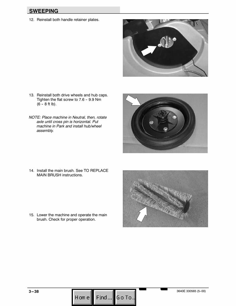
12. Reinstall both handle retainer plates.
13. Reinstall both drive wheels and hub caps.Tighten the flat screw to 7.6 -- 9.9 Nm(6 -- 8 ft lb).
NOTE: Place machine in Neutral, then, rotateaxle until cross pin is horizontal. Putmachine in Park and install hub/wheelassembly.
14. Install the main brush. See TO REPLACEMAIN BRUSH instructions.
15. Lower the machine and operate the mainbrush. Check for proper operation.

SWEEPING
3--393640E 330565 (5--00)
TO REMOVE MAIN BRUSH SHAFT
FOR SAFETY: Before Leaving Or ServicingMachine; Stop On Level Surface, Place ShifterIn Park.
1. Lower the main brush to the float position.
2. Go to the back of the machine and locatethe brush shaft running between the left andright brush arms.
3. Remove the tension spring from the rightside of the brush shaft.

SWEEPING
3--40 3640E 330565 (5--00)
4. Remove the two hex screws, sleeves, andnuts holding the brush shaft to the brusharms.
5. Remove the two hex screws, sleeves, andnuts holding the brush shaft to the upperpivot bar. Remove the brush shaft from themachine.
SWEEPING
3--413640E 330565 (5--00)
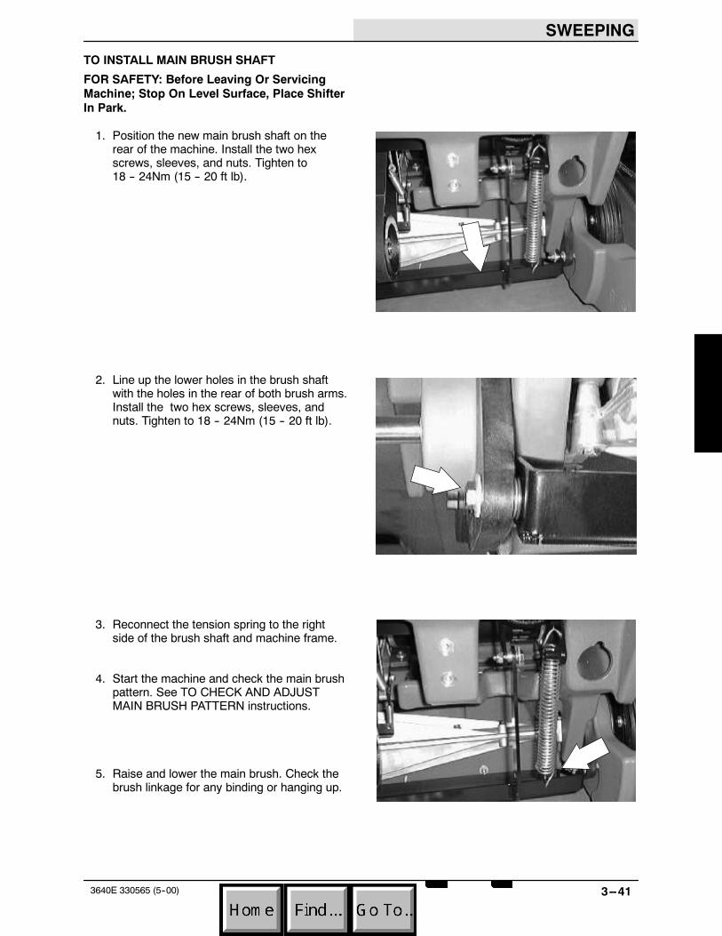
TO INSTALL MAIN BRUSH SHAFT
FOR SAFETY: Before Leaving Or ServicingMachine; Stop On Level Surface, Place ShifterIn Park.
1. Position the new main brush shaft on therear of the machine. Install the two hexscrews, sleeves, and nuts. Tighten to18 -- 24Nm (15 -- 20 ft lb).
2. Line up the lower holes in the brush shaftwith the holes in the rear of both brush arms.Install the two hex screws, sleeves, andnuts. Tighten to 18 -- 24Nm (15 -- 20 ft lb).
3. Reconnect the tension spring to the rightside of the brush shaft and machine frame.
4. Start the machine and check the main brushpattern. See TO CHECK AND ADJUSTMAIN BRUSH PATTERN instructions.
5. Raise and lower the main brush. Check thebrush linkage for any binding or hanging up.

SWEEPING
3--42 3640E 330565 (5--00)
SIDE BRUSH
The standard machine is equipped with a righthand side brush. A left hand side brush isoptional. Both left and right side brushes aredriven with an electric motor.
TO REPLACE LH OR RH SIDE BRUSH
FOR SAFETY: Before Leaving Or ServicingMachine; Stop On Level Surface, Place ShifterIn Park.
1. Make sure the side brush lever is in theraised position.
2. Go under the side brush and locate the hairpin clip on the bottom of the side brushmotor shaft. Pull the pin out.
NOTE: Some early models have two spacerwashers under the hairpin.

SWEEPING
3--433640E 330565 (5--00)
3. The side brush will drop off the side brushshaft. Remove the brush from the machine.
4. Position the new side brush under the frontof the machine in the area of the side brushmotor.
5. Lift the side brush up and onto the sidebrush motor shaft. Make sure the slots in thetop of the side brush line up with the pin onthe side brush motor shaft.
6. Reinstall the hair pin clip in the bottom of theside brush motor shaft.
7. Start the machine and check the side brushfor proper operation.
SWEEPING
3--44 3640E 330565 (5--00)
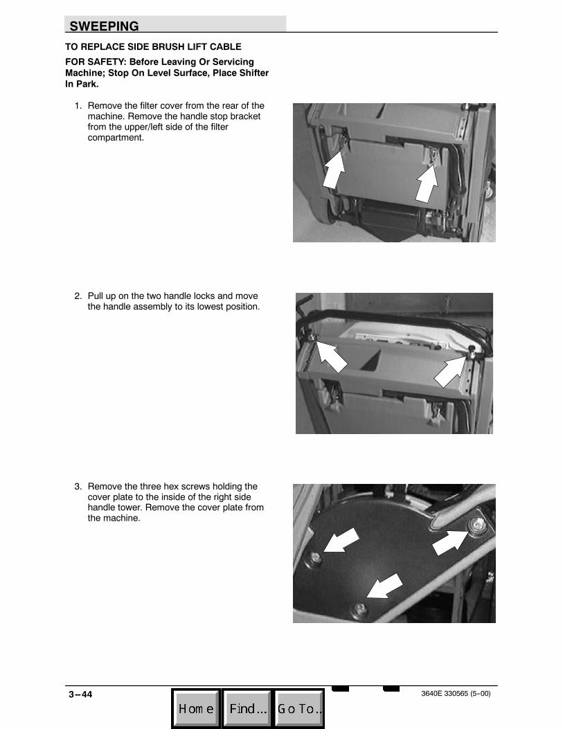
TO REPLACE SIDE BRUSH LIFT CABLE
FOR SAFETY: Before Leaving Or ServicingMachine; Stop On Level Surface, Place ShifterIn Park.
1. Remove the filter cover from the rear of themachine. Remove the handle stop bracketfrom the upper/left side of the filtercompartment.
2. Pull up on the two handle locks and movethe handle assembly to its lowest position.
3. Remove the three hex screws holding thecover plate to the inside of the right sidehandle tower. Remove the cover plate fromthe machine.
SWEEPING
3--453640E 330565 (5--00)
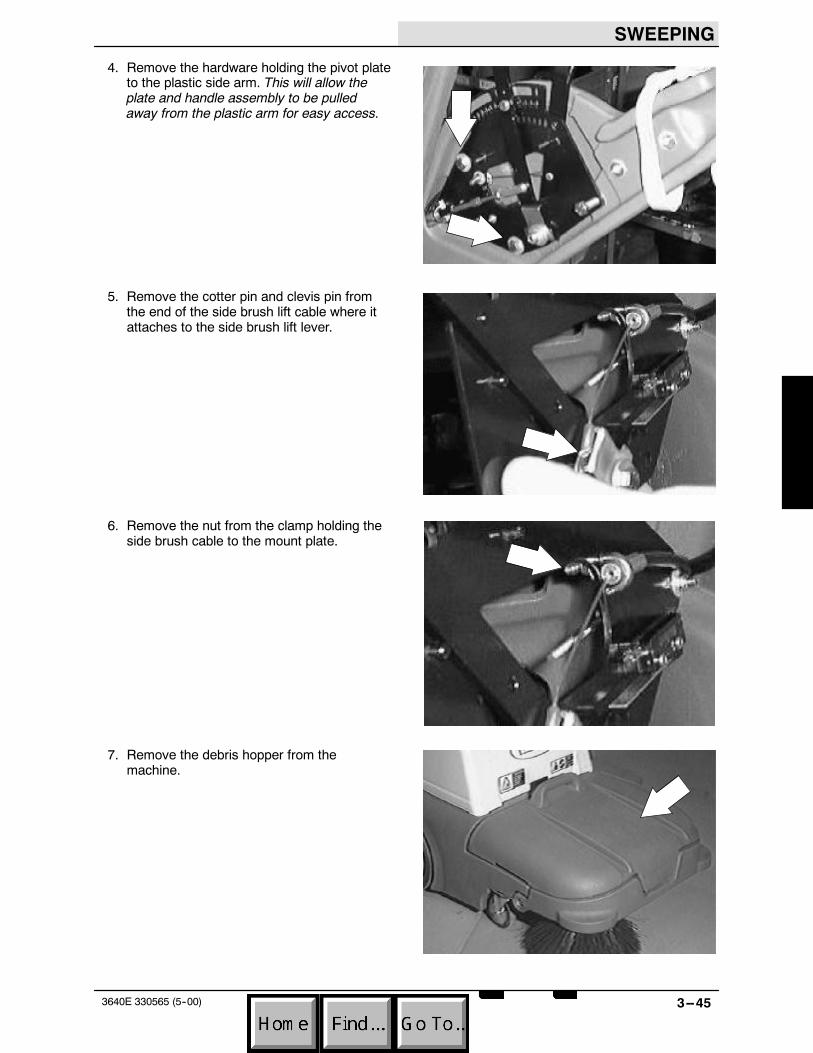
4. Remove the hardware holding the pivot plateto the plastic side arm. This will allow theplate and handle assembly to be pulledaway from the plastic arm for easy access.
5. Remove the cotter pin and clevis pin fromthe end of the side brush lift cable where itattaches to the side brush lift lever.
6. Remove the nut from the clamp holding theside brush cable to the mount plate.
7. Remove the debris hopper from themachine.
SWEEPING
3--46 3640E 330565 (5--00)
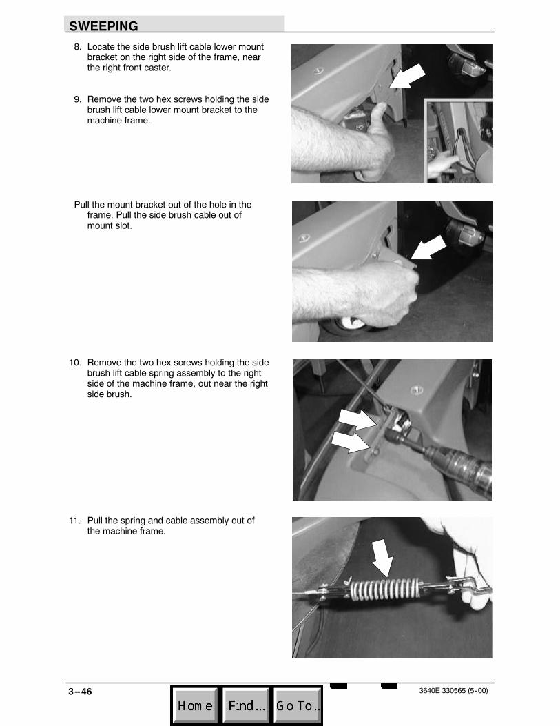
8. Locate the side brush lift cable lower mountbracket on the right side of the frame, nearthe right front caster.
9. Remove the two hex screws holding the sidebrush lift cable lower mount bracket to themachine frame.
Pull the mount bracket out of the hole in theframe. Pull the side brush cable out ofmount slot.
10. Remove the two hex screws holding the sidebrush lift cable spring assembly to the rightside of the machine frame, out near the rightside brush.
11. Pull the spring and cable assembly out ofthe machine frame.
SWEEPING
3--473640E 330565 (5--00)
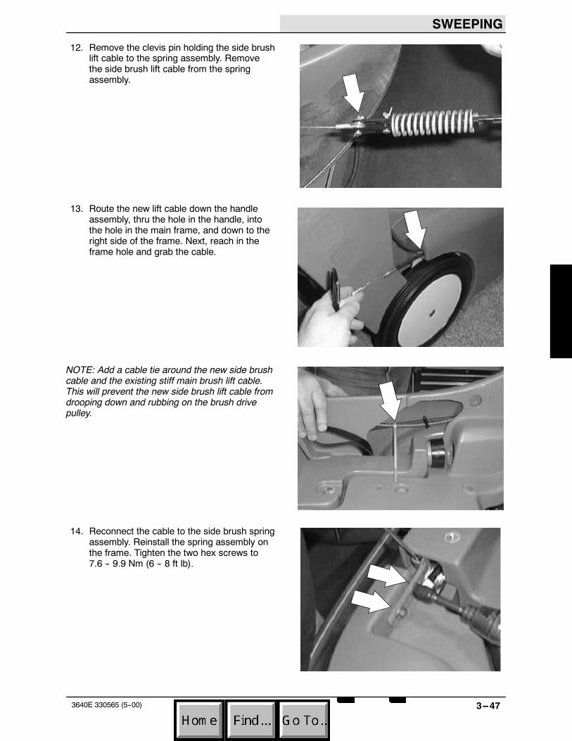
12. Remove the clevis pin holding the side brushlift cable to the spring assembly. Removethe side brush lift cable from the springassembly.
13. Route the new lift cable down the handleassembly, thru the hole in the handle, intothe hole in the main frame, and down to theright side of the frame. Next, reach in theframe hole and grab the cable.
NOTE: Add a cable tie around the new side brushcable and the existing stiff main brush lift cable.This will prevent the new side brush lift cable fromdrooping down and rubbing on the brush drivepulley.
14. Reconnect the cable to the side brush springassembly. Reinstall the spring assembly onthe frame. Tighten the two hex screws to7.6 -- 9.9 Nm (6 -- 8 ft lb).

SWEEPING
3--48 3640E 330565 (5--00)
15. Position the side brush lift cable in the sloton the lower mount bracket. Reinstall thelower mount bracket in the machine. Tightenthe two hex screws to 8 -- 24Nm(15 -- 20 ft lb).
16. Go up to the main brush lift lever and installthe nut on the main brush lift cable mountclamp. Tighten the nut to 7.6 -- 9.9 Nm(6 -- 8 ft lb).
17. Install the clevis pin and cotter pin in the endof the new cable where it attaches to theside brush lift lever.
18. Position the brush lift lever assembly backonto the right handle arm.
SWEEPING
3--493640E 330565 (5--00)
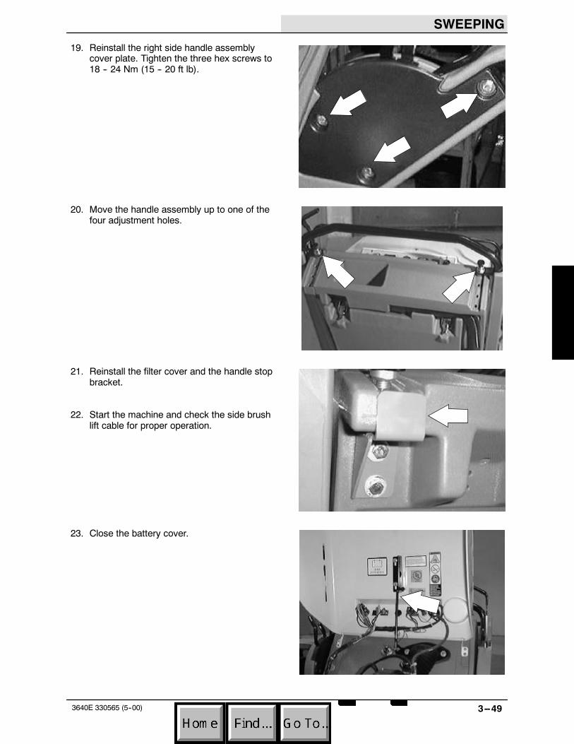
19. Reinstall the right side handle assemblycover plate. Tighten the three hex screws to18 -- 24 Nm (15 -- 20 ft lb).
20. Move the handle assembly up to one of thefour adjustment holes.
21. Reinstall the filter cover and the handle stopbracket.
22. Start the machine and check the side brushlift cable for proper operation.
23. Close the battery cover.
SWEEPING
3--50 3640E 330565 (5--00)
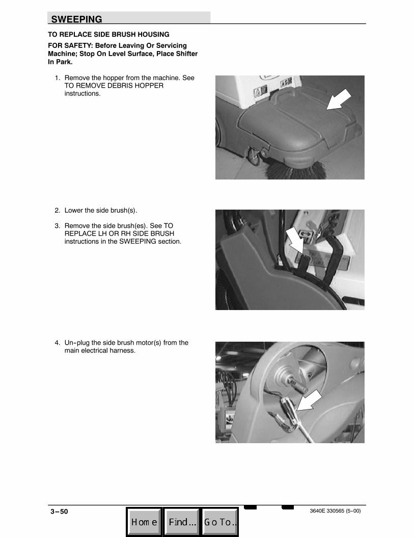
TO REPLACE SIDE BRUSH HOUSING
FOR SAFETY: Before Leaving Or ServicingMachine; Stop On Level Surface, Place ShifterIn Park.
1. Remove the hopper from the machine. SeeTO REMOVE DEBRIS HOPPERinstructions.
2. Lower the side brush(s).
3. Remove the side brush(es). See TOREPLACE LH OR RH SIDE BRUSHinstructions in the SWEEPING section.
4. Un--plug the side brush motor(s) from themain electrical harness.

SWEEPING
3--513640E 330565 (5--00)
5. Remove the four hex screws holding theside brush motor(s) and gear box(s) to theside brush housing.
6. Remove the side brush motor(s) and gearbox(s) from the machine.
7. Remove the two screws holding the sidebrush lift cable assembly to the side brushhousing.
8. Remove the hex screw and sleeve from theleft side of the side brush housing.

SWEEPING
3--52 3640E 330565 (5--00)
9. SLOWLY remove the hex screw from theright side of the side brush housing.
NOTE: There is a large spring that is undertension in the right side of the side brushhousing. This spring will partially un--windwhen the right hex screw and sleeve areremoved. If your machine is equipped withdual side brushes----there is a tension springon both sides.
10. Position the new side brush housing in frontof the machine. If your machine has a RHside brush only----place the sleeve in thehole in the left arm of the housing. Bring thatend up and line up the hole in the sleevewith the threaded insert in the main frame.Install the hex screw----but leave loose fornow.
11. Go the right side arm of the housing andposition the tension spring in the openingwhere the sleeve is inserted. Once thespring is positioned correctly----place thesleeve through the arm holes and the centerof the tension spring. Bring that end upcarefully, making sure the spring is pulledback and one end placed down the mainmachine frame. Line up the hole in thesleeve with the threaded insert in the mainframe. Install the hex screw, Tighten bothscrews to 28 -- 36 Nm (20 -- 26 ft lb).
NOTE:Repeat this procedure on the left side ifyour machine is equipped with dual side brushes.
12. Reinstall the side brush lift cable bracket onthe side brush housing. Tighten the twoscrews to 7.6 -- 9.9 Nm (6 -- 8 ft lb).
NOTE: Push the housing down to install thehardware. Lift up on the front of the housing andpush the side brush bracket toward the rear of themachine. Tighten the hardware.

SWEEPING
3--533640E 330565 (5--00)
13. Position the side brush motor(s) and gearbox(s) in the machine. Line up the mountholes in the side brush housing with themount holes in the side brush motor.
14. Reinstall the hex screws and tighten to7.6 -- 9.9 Nm (6 -- 8 ft lb).
15. Reconnect the side brush motor(s) to themain harness. See schematic in theELECTRICAL section.
16. Reinstall the side brush(es). See TOREPLACE LH OR RH SIDE BRUSHinstructions in the SWEEPING section.
17. Operate the machine and check the sidebrush for proper operation.
SWEEPING
3--54 3640E 330565 (5--00)
SKIRTS AND SEALS
The skirts and seals on the model 3640 are usedto contain dust and debris during the sweepingoperation. The skirts and seals must be free oftears or damage to achieve the best sweepingperformance. Inspect and replace any damagedskirt or seal.
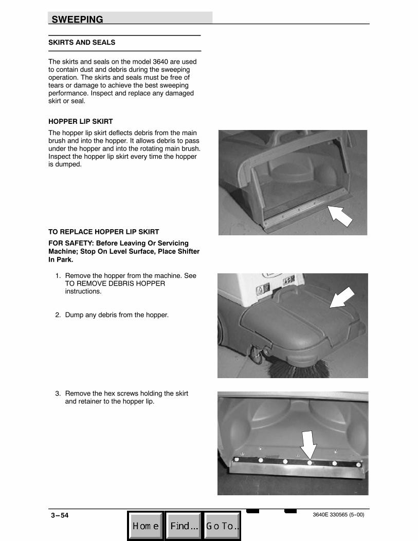
HOPPER LIP SKIRT
The hopper lip skirt deflects debris from the mainbrush and into the hopper. It allows debris to passunder the hopper and into the rotating main brush.Inspect the hopper lip skirt every time the hopperis dumped.
TO REPLACE HOPPER LIP SKIRT
FOR SAFETY: Before Leaving Or ServicingMachine; Stop On Level Surface, Place ShifterIn Park.
1. Remove the hopper from the machine. SeeTO REMOVE DEBRIS HOPPERinstructions.
2. Dump any debris from the hopper.
3. Remove the hex screws holding the skirtand retainer to the hopper lip.

SWEEPING
3--553640E 330565 (5--00)
4. Remove the skirt and retainer from themachine. Discard the skirt.
5. Position the new skirt and existing retaineron the hopper. Reinstall the hardware andtighten to 7.6 -- 9.9 Nm (6 -- 8 ft lb).
6. Reinstall the debris hopper. See TOINSTALL DEBRIS HOPPER instructions.

SWEEPING
3--56 3640E 330565 (5--00)
REAR SKIRT
The rear skirt and recirculation flap are used tocontain any debris and help create a vacuumchamber around the main brush. The rear skirtshould be adjusted slightly off the ground to allowair flow and avoid any dusting problems.
TO REPLACE REAR SKIRT/RECIRCULATION FLAP
FOR SAFETY: Before Leaving Or ServicingMachine; Stop On Level Surface, Place ShifterIn Park.
1. Remove the hopper from the machine. SeeTO REMOVE DEBRIS HOPPERinstructions.
2. Remove the main brush. See TO REPLACEMAIN BRUSH instructions.

SWEEPING
3--573640E 330565 (5--00)
3. Remove the five nuts from the back of thebrush wrap. Remove and retain the five boltplates.
4. Remove the rear skirt/recirculation flap fromthe machine.
5. Install the new rear skirt/recirculation flap onthe machine. Lift the rear skirt/recirculationflap and install the five bolt plates throughthe rear skirt/recirculation flap and themachine frame. Install the five nuts andlightly tighten.
6. Reinstall the main brush. See TO REPLACEMAIN BRUSH instructions.
7. Reinstall the hopper in the machine. See TOINSTALL DEBRIS HOPPER instructions.
8. Operate the machine and check for propersweeping operation.

SWEEPING
3--58 3640E 330565 (5--00)
UPPER HOPPER SEAL
The upper hopper seal is used to seal the back ofthe hopper to the machine frame. This sealprevents dust and debris from being expelledoutside the brush compartment area.
TO REPLACE UPPER HOPPER SEAL
FOR SAFETY: Before Leaving Or ServicingMachine; Stop On Level Surface, Place ShifterIn Park.
1. Remove the hopper from the machine. SeeTO REMOVE DEBRIS HOPPERinstructions.
2. Lift the upper hopper seal up slightly andlocate the plastic rivets holding the seal tothe machine.

SWEEPING
3--593640E 330565 (5--00)
3. Un--screw the center pin out of the plasticrivets. Lift the body of the rivet out of thehole. Repeat on the rest of the rivets.
4. Remove the old upper hopper seal from themachine.
5. Position the new upper hopper seal on themachine. Line up the holes in the seal withthe mount holes in the machine frame.
6. Install the plastic rivets in the mount holes.Start by placing the body of the rivet in thehole first, then screw the center pin into thebody until it snaps in place.
7. Reinstall the hopper in the machine. See TOINSTALL DEBRIS HOPPER instructions.
SWEEPING
3--60 3640E 330565 (5--00)
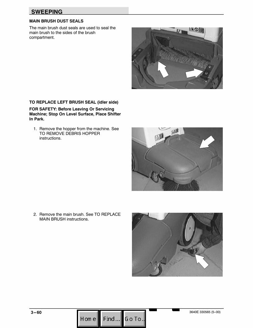
MAIN BRUSH DUST SEALS
The main brush dust seals are used to seal themain brush to the sides of the brushcompartment.
TO REPLACE LEFT BRUSH SEAL (idler side)
FOR SAFETY: Before Leaving Or ServicingMachine; Stop On Level Surface, Place ShifterIn Park.
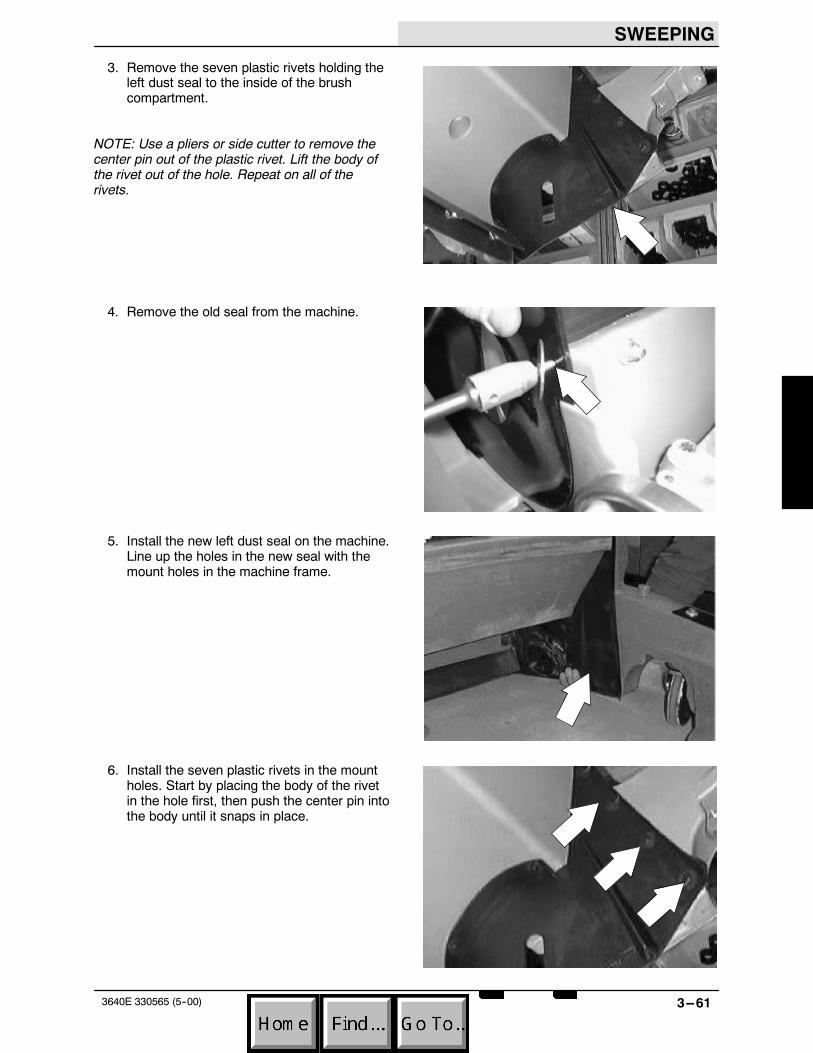
1. Remove the hopper from the machine. SeeTO REMOVE DEBRIS HOPPERinstructions.
2. Remove the main brush. See TO REPLACEMAIN BRUSH instructions.
SWEEPING
3--613640E 330565 (5--00)
3. Remove the seven plastic rivets holding theleft dust seal to the inside of the brushcompartment.
NOTE: Use a pliers or side cutter to remove thecenter pin out of the plastic rivet. Lift the body ofthe rivet out of the hole. Repeat on all of therivets.
4. Remove the old seal from the machine.
5. Install the new left dust seal on the machine.Line up the holes in the new seal with themount holes in the machine frame.
6. Install the seven plastic rivets in the mountholes. Start by placing the body of the rivetin the hole first, then push the center pin intothe body until it snaps in place.

SWEEPING
3--62 3640E 330565 (5--00)
7. Reinstall the main brush. See TO REPLACEMAIN BRUSH instructions.
8. Reinstall the hopper in the machine. See TOINSTALL DEBRIS HOPPER instructions.
SWEEPING
3--633640E 330565 (5--00)
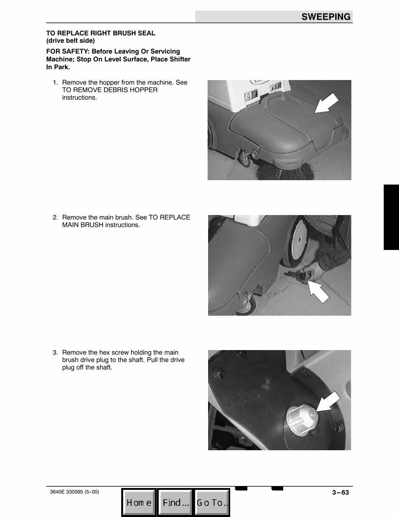
TO REPLACE RIGHT BRUSH SEAL(drive belt side)
FOR SAFETY: Before Leaving Or ServicingMachine; Stop On Level Surface, Place ShifterIn Park.
1. Remove the hopper from the machine. SeeTO REMOVE DEBRIS HOPPERinstructions.
2. Remove the main brush. See TO REPLACEMAIN BRUSH instructions.
3. Remove the hex screw holding the mainbrush drive plug to the shaft. Pull the driveplug off the shaft.
SWEEPING
3--64 3640E 330565 (5--00)
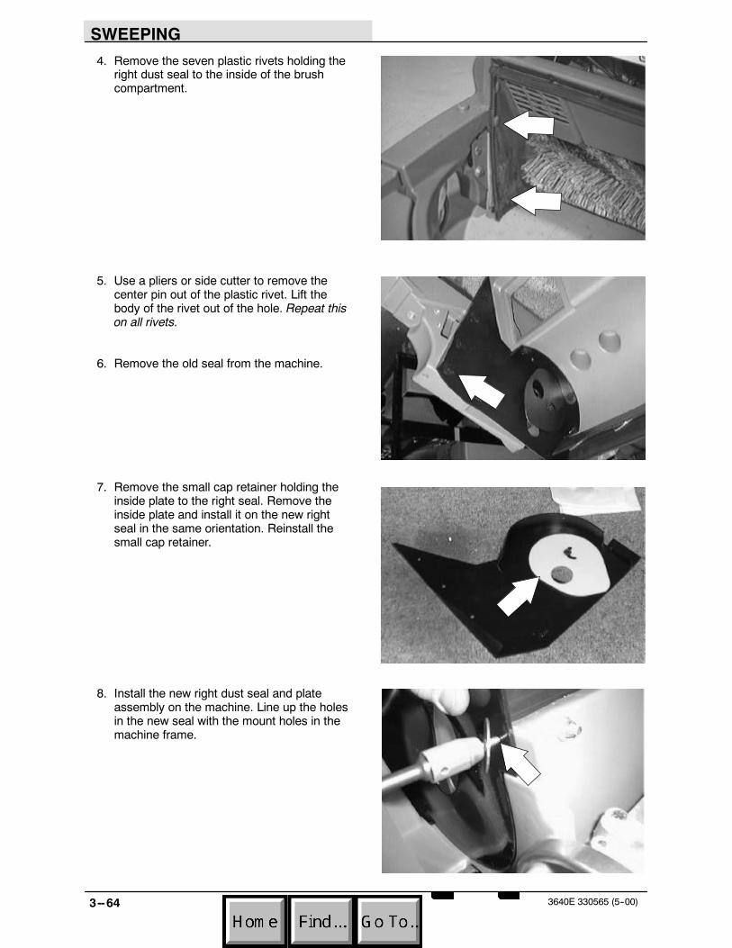
4. Remove the seven plastic rivets holding theright dust seal to the inside of the brushcompartment.
5. Use a pliers or side cutter to remove thecenter pin out of the plastic rivet. Lift thebody of the rivet out of the hole. Repeat thison all rivets.
6. Remove the old seal from the machine.
7. Remove the small cap retainer holding theinside plate to the right seal. Remove theinside plate and install it on the new rightseal in the same orientation. Reinstall thesmall cap retainer.
8. Install the new right dust seal and plateassembly on the machine. Line up the holesin the new seal with the mount holes in themachine frame.

SWEEPING
3--653640E 330565 (5--00)
9. Install the seven plastic rivets in the mountholes. Start by placing the body of the rivetin the hole first, then push the center pin intothe body until it snaps in place.
10. Reinstall the main brush drive plug on theshaft. Make sure the key is in place on theshaft. Reinstall the hex screw and tighten to7.6 -- 9.9 Nm (6 -- 8 ft lb).
11. Reinstall the main brush. See TO REPLACEMAIN BRUSH instructions.
12. Reinstall the hopper in the machine. See TOINSTALL DEBRIS HOPPER instructions.

SWEEPING
3--66 3640E 330565 (5--00)
VACUUM FAN
The vacuum fan pulls air from the main brushcompartment and through the filter assembly. Thefilter bag (standard) is removed and discardedafter it becomes full. The panel filter (optional) canbe cleaned with the filter shaker or can beremoved and cleaned outside of the machine.
TO REMOVE VACUUM FAN ASSEMBLY
FOR SAFETY: Before Leaving Or ServicingMachine; Stop On Level Surface, Place ShifterIn Park.
1. Open the battery cover.
2. Remove the air duct running from the top ofthe vacuum fan to the front wall of the dustfilter.

SWEEPING
3--673640E 330565 (5--00)
3. Remove the clamp holding the cable to thetop of the vacuum fan housing.
4. Locate the tension bolt and slotted bracketon the side of vacuum fan opposite theV--belt pulley. Remove the tension bolt.
5. Let the vacuum fan drop down. Remove theV--belt from the pulley on the fan.
6. Remove the hex screw and nut holding thevacuum fan assembly to the pivot mountbracket. Remove the vacuum fan from themachine.

SWEEPING
3--68 3640E 330565 (5--00)
TO INSTALL VACUUM FAN ASSEMBLY
FOR SAFETY: Before Leaving Or ServicingMachine; Stop On Level Surface, Place ShifterIn Park.
1. Open the battery cover.
2. Position the vacuum fan assembly in themachine. Line up the mount hole in the pivotbracket with the pivot mount on the fanhousing. Install the hex screw and nut.Tighten so the vacuum fan can pivot freelyfor belt tensioning.
3. Install the bolt in the tension slot andvacuum fan housing. Leave loose for now.
SWEEPING
3--693640E 330565 (5--00)
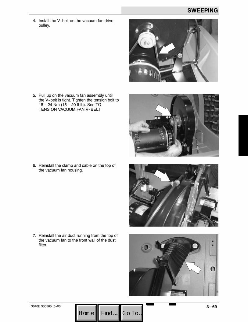
4. Install the V--belt on the vacuum fan drivepulley.
5. Pull up on the vacuum fan assembly untilthe V--belt is tight. Tighten the tension bolt to18 -- 24 Nm (15 -- 20 ft lb). See TOTENSION VACUUM FAN V--BELT
6. Reinstall the clamp and cable on the top ofthe vacuum fan housing.
7. Reinstall the air duct running from the top ofthe vacuum fan to the front wall of the dustfilter.

SWEEPING
3--70 3640E 330565 (5--00)
8. Close the battery cover.
9. Start the machine and check the vacuum fanfor proper operation.
SWEEPING
3--713640E 330565 (5--00)
TO REPLACE VACUUM FAN IMPELLER
FOR SAFETY: Before Leaving Or ServicingMachine; Stop On Level Surface, Place ShifterIn Park.
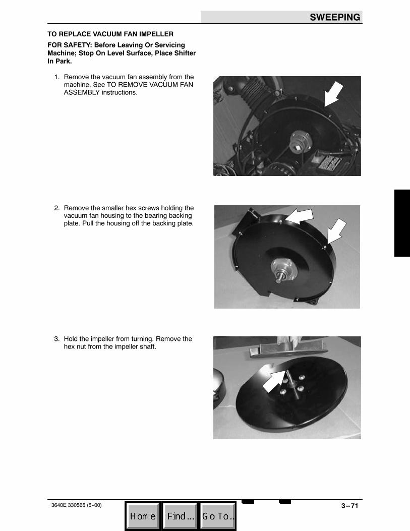
1. Remove the vacuum fan assembly from themachine. See TO REMOVE VACUUM FANASSEMBLY instructions.
2. Remove the smaller hex screws holding thevacuum fan housing to the bearing backingplate. Pull the housing off the backing plate.
3. Hold the impeller from turning. Remove thehex nut from the impeller shaft.
SWEEPING
3--72 3640E 330565 (5--00)
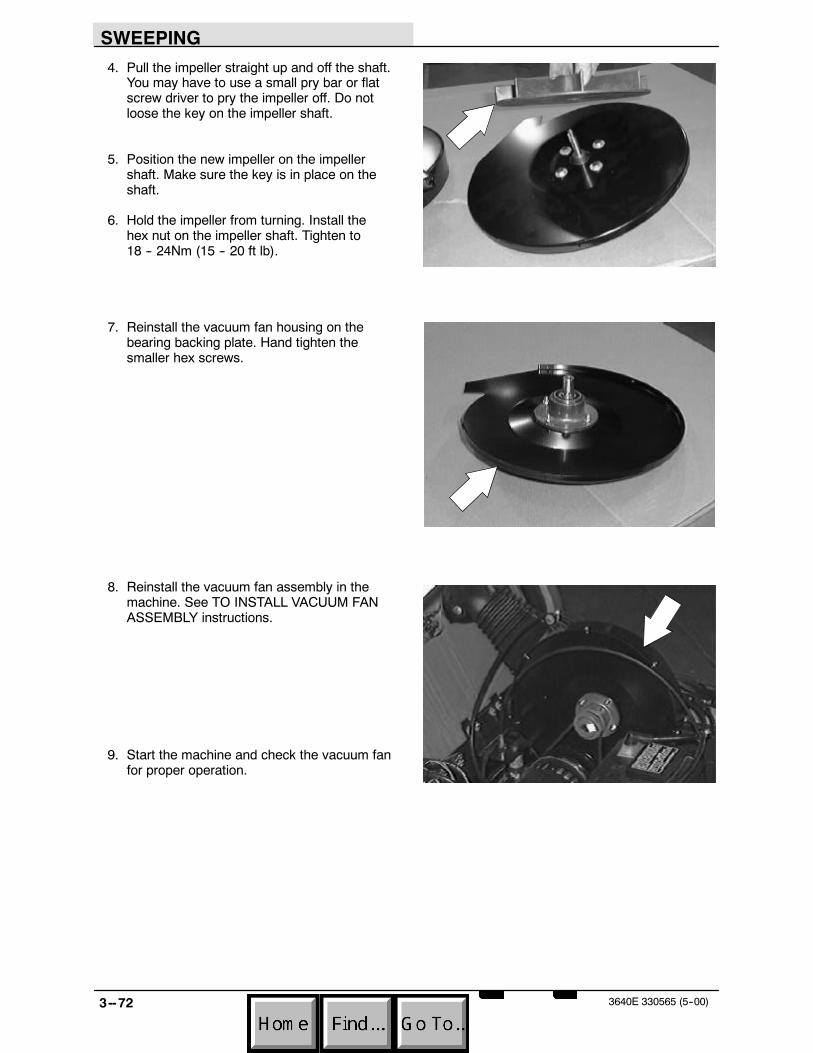
4. Pull the impeller straight up and off the shaft.You may have to use a small pry bar or flatscrew driver to pry the impeller off. Do notloose the key on the impeller shaft.
5. Position the new impeller on the impellershaft. Make sure the key is in place on theshaft.
6. Hold the impeller from turning. Install thehex nut on the impeller shaft. Tighten to18 -- 24Nm (15 -- 20 ft lb).
7. Reinstall the vacuum fan housing on thebearing backing plate. Hand tighten thesmaller hex screws.
8. Reinstall the vacuum fan assembly in themachine. See TO INSTALL VACUUM FANASSEMBLY instructions.
9. Start the machine and check the vacuum fanfor proper operation.

SWEEPING
3--733640E 330565 (5--00)
TO REPLACE VACUUM FAN IMPELLERBEARINGS
FOR SAFETY: Before Leaving Or ServicingMachine; Stop On Level Surface, Place ShifterIn Park.
1. Remove the vacuum fan assembly from themachine. See TO REMOVE VACUUM FANASSEMBLY instructions.
2. Remove the smaller hex screws holding thevacuum fan housing to the bearing backingplate. Pull the housing off the backing plate.
3. Hold the impeller from turning. Remove thehex nut from the impeller shaft.

SWEEPING
3--74 3640E 330565 (5--00)
4. Pull the impeller straight up and off the shaft.You may have to use a small pry bar or flatscrew driver to pry the impeller off. Do notloose the key on the impeller shaft.
5. Remove the four hex screws and nutsholding the bearing and pulley assembly tothe backing plate. Remove the bearingassembly.
6. Loosen the set screws on the impeller beltpulley. Slide the pulley off the impeller shaft.
NOTE:Make sure to mark the location of thepulley on the impeller shaft for properre--assembly.
7. Use a press to remove the impeller shaftand inner bearing from the bearing housing.Press the bearing and shaft in the directionof the fan shaft.
8. Press the second bearing out of thehousing.

SWEEPING
3--753640E 330565 (5--00)
9. Press a new bearing in the housing on thepulley side. Press the bearing in until thesnap ring contacts the housing.
10. Press the impeller shaft into the newbearing. Note: the impeller side of the shaftmust be on the flange side of the bearinghousing.
11. Press the second bearing into the housingover the impeller shaft. Press the bearing inuntil the snap ring contacts the housing.
12. Reinstall the bearing assembly on thebacking plate. Reinstall the hardware andtighten to 7.6 -- 9.9 Nm (6 -- 8 ft lb).

SWEEPING
3--76 3640E 330565 (5--00)
13. Reinstall the pulley on the larger diameterend of the impeller shaft. Make sure thepulley is positioned in the same location as itwas removed. Hand tighten the set screwstight.
14. Reinstall the impeller on the impeller shaft.Make sure the key is in place on the shaft.
15. Hold the impeller from turning. Install thehex nut on the impeller shaft. Tighten to18 -- 24Nm (15 -- 20 ft lb).
16. Reinstall the vacuum fan housing on thebearing backing plate. Hand tighten thesmaller hex screws.
17. Reinstall the vacuum fan assembly in themachine. See TO INSTALL VACUUM FANASSEMBLY instructions.
18. Start the machine and check the vacuum fanfor proper operation.

SWEEPING
3--773640E 330565 (5--00)
TO TENSION VACUUM FAN V--BELT
FOR SAFETY: Before Leaving Or ServicingMachine; Stop On Level Surface, Place ShifterIn Park.
1. Open the battery cover.
2. Locate the tension bolt and slotted bracketon the side of vacuum fan opposite theV--belt pulley. Loosen the tension bolt.
3. Pull up on the vacuum fan assembly untilthe V--belt is tight. Check belt tension byapplying a force 1 kg (2 lb) at belt midpoint.The proper deflection should be 5 mm(0.09 in).Tighten the tension bolt to18 -- 24 Nm (15 -- 20 ft lb).

SWEEPING
3--78 3640E 330565 (5--00)
4. Close the battery cover.
5. Start the machine and check the vacuum fanfor proper operation.
SWEEPING
3--793640E 330565 (5--00)
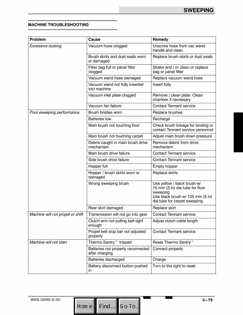
MACHINE TROUBLESHOOTING
Problem Cause Remedy
Excessive dusting Vacuum hose clogged Unscrew hose from vac wandhandle and clean
Brush skirts and dust seals wornor damaged
Replace brush skirts or dust seals
Filter bag full or panel filterclogged
Shake and / or clean or replacebag or panel filter
Vacuum wand hose damaged Replace vacuum wand hose
Vacuum wand not fully insertedinto machine
Insert fully
Vacuum inlet plate clogged Remove / clean plate. Cleanchamber if necessary
Vacuum fan failure Contact Tennant service
Poor sweeping performance Brush bristles worn Replace brushes
Batteries low Recharge
Main brush not touching floor Check brush linkage for binding orcontact Tennant service personnel
Main brush not touching carpet Adjust main brush down pressure
Debris caught in main brush drivemechanism
Remove debris from drivemechanism
Main brush drive failure Contact Tennant service
Side brush drive failure Contact Tennant service
Hopper full Empty hopper
Hopper / brush skirts worn ordamaged
Replace skirts
Wrong sweeping brush Use yellow / black brush w/75 mm (3 in) dia tube for floorsweepingUse black brush w/ 125 mm (5 in)dia tube for carpet sweeping
Rear skirt damaged Replace skirt
Machine will not propel or shift Transmission will not go into gear Contact Tennant serviceMachine will not propel or shift
Clutch arm not pulling belt tightenough
Adjust clutch cable length
Propel belt stop bar not adjustedproperly
Contact Tennant service
Machine will not start Thermo Sentryt tripped Reset Thermo SentrytMachine will not start
Batteries not properly reconnectedafter charging
Connect properly
Batteries discharged Charge
Battery disconnect button pushedin
Turn to the right to reset

SWEEPING
3--80 3640E 330565 (5--00)
ELECTRICAL
4--13640E 330565 (5--00)
CONTENTS
Page
INTRODUCTION 4--3. . . . . . . . . . . . . . . . . . . . . .ELECTRICAL SYSTEM 4--4. . . . . . . . . . . . . . . .
BATTERIES 4--5. . . . . . . . . . . . . . . . . . . . . . .TO CHARGE BATTERIES 4--6. . . . . . . .TO REPLACE BATTERIES 4--9. . . . . . .
INSTRUMENT PANEL 4--11. . . . . . . . . . . . . . . .BATTERY DISCHARGE INDICATOR 4--11. . .BATTERY DISCONNECT BUTTON
(OPTION) 4--11. . . . . . . . . . . . . . . . . . . . . . . .HOURMETER 4--12. . . . . . . . . . . . . . . . . . . . . . .FILTER SHAKER MOTOR SWITCH
(OPTION) 4--12. . . . . . . . . . . . . . . . . . . . . . . .IGNITION KEY SWITCH 4--12. . . . . . . . . . . . . .CIRCUIT BREAKERS 4--13. . . . . . . . . . . . . . . .
TO REPLACE 15 AMP CIRCUITBREAKER 4--13. . . . . . . . . . . . . . . . . . . . .
TO REPLACE 50 AMP CIRCUITBREAKER 4--16. . . . . . . . . . . . . . . . . . . . .
TO REPLACE MAIN CONTACTOR 4--19. .TO REPLACE ELECTRICAL RELAY 4--22.
ELECTRIC MOTORS 4--24. . . . . . . . . . . . . . . . .TO REMOVE MAIN DRIVE MOTOR 4--24.TO INSTALL MAIN DRIVE MOTOR 4--28. .TO REPLACE FILTER SHAKER
MOTOR (OPTION) 4--31. . . . . . . . . . . . .TO REPLACE SIDE BRUSH MOTOR 4--34TO REPLACE SIDE BRUSH SWITCH 4--37ELECTRIC MOTOR AMP DRAW
CHART 4--41. . . . . . . . . . . . . . . . . . . . . . .ELECTRICAL SCHEMATIC 4--42. . . . . . . . . . . .TROUBLESHOOTING 4--43. . . . . . . . . . . . . . . .
MAIN MOTORTROUBLESHOOTING 4--44. . . . . . . . . .
FILTER SHAKERTROUBLESHOOTING 4--46. . . . . . . . . .

ELECTRICAL
4--2 3640E 330565 (5--00)

ELECTRICAL
4--33640E 330565 (5--00)
INTRODUCTION
This section includes information on machineelectrical components such as relays, circuitbreakers, switches, and wiring harness.
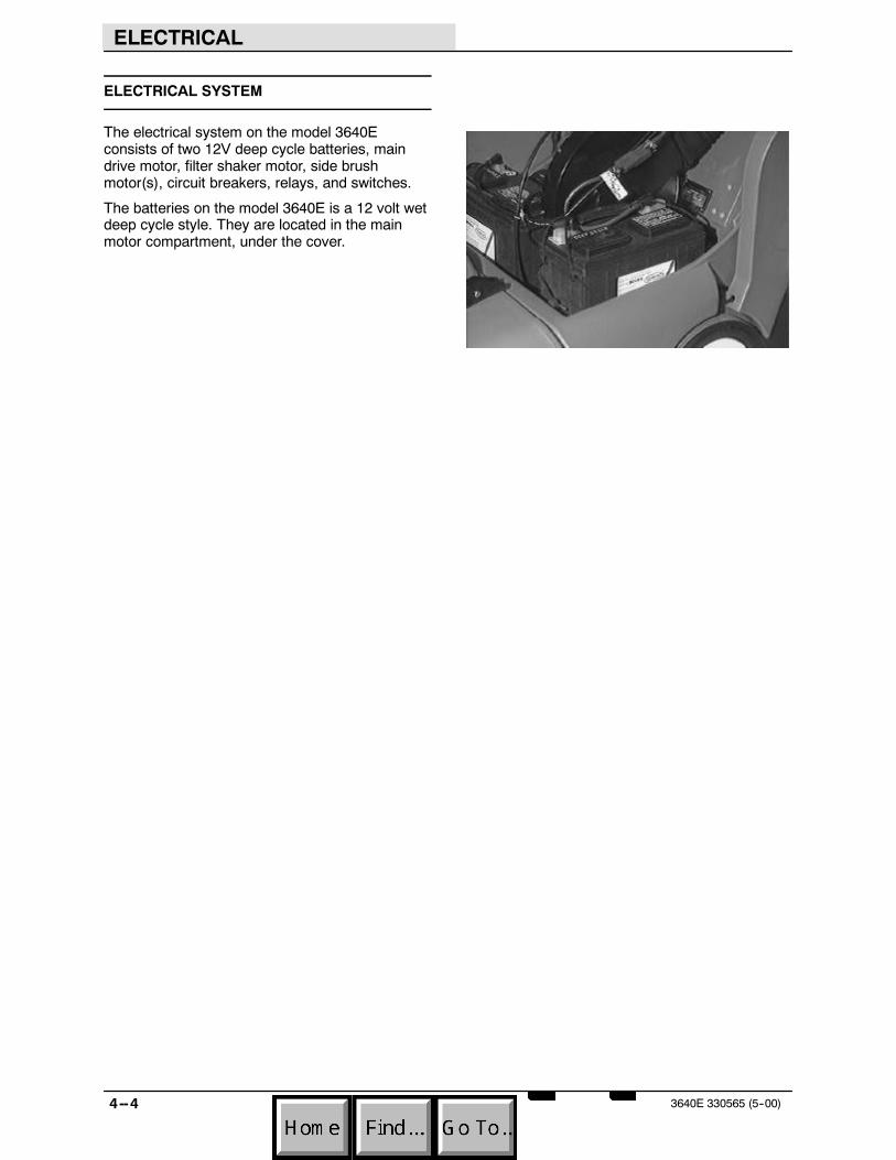
ELECTRICAL
4--4 3640E 330565 (5--00)
ELECTRICAL SYSTEM
The electrical system on the model 3640Econsists of two 12V deep cycle batteries, maindrive motor, filter shaker motor, side brushmotor(s), circuit breakers, relays, and switches.
The batteries on the model 3640E is a 12 volt wetdeep cycle style. They are located in the mainmotor compartment, under the cover.
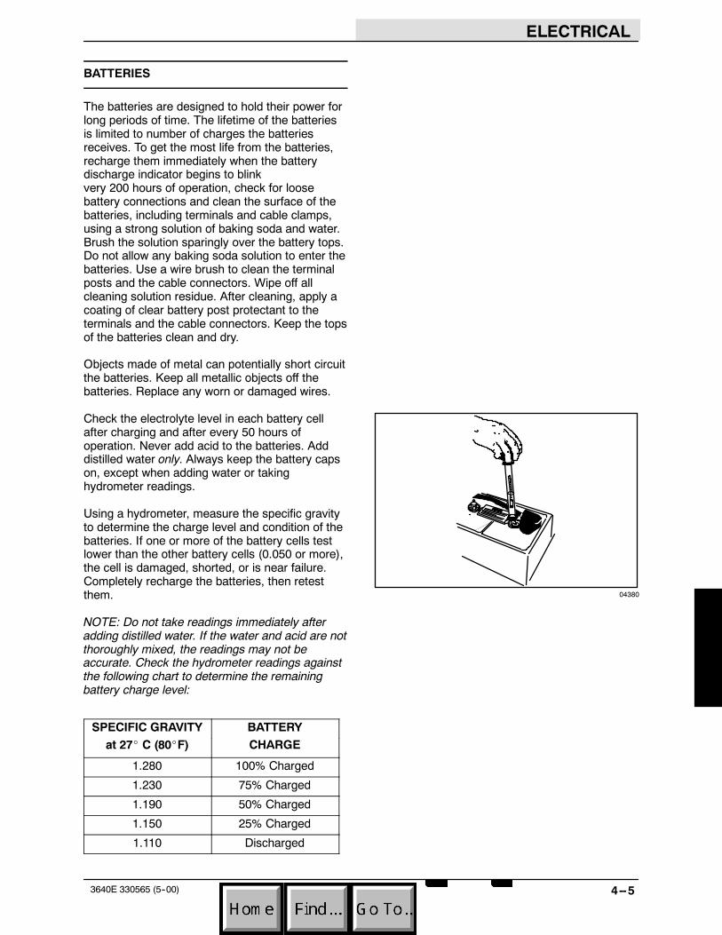
ELECTRICAL
4--53640E 330565 (5--00)
BATTERIES
The batteries are designed to hold their power forlong periods of time. The lifetime of the batteriesis limited to number of charges the batteriesreceives. To get the most life from the batteries,recharge them immediately when the batterydischarge indicator begins to blinkvery 200 hours of operation, check for loosebattery connections and clean the surface of thebatteries, including terminals and cable clamps,using a strong solution of baking soda and water.Brush the solution sparingly over the battery tops.Do not allow any baking soda solution to enter thebatteries. Use a wire brush to clean the terminalposts and the cable connectors. Wipe off allcleaning solution residue. After cleaning, apply acoating of clear battery post protectant to theterminals and the cable connectors. Keep the topsof the batteries clean and dry.
Objects made of metal can potentially short circuitthe batteries. Keep all metallic objects off thebatteries. Replace any worn or damaged wires.
Check the electrolyte level in each battery cellafter charging and after every 50 hours ofoperation. Never add acid to the batteries. Adddistilled water only. Always keep the battery capson, except when adding water or takinghydrometer readings.
Using a hydrometer, measure the specific gravityto determine the charge level and condition of thebatteries. If one or more of the battery cells testlower than the other battery cells (0.050 or more),the cell is damaged, shorted, or is near failure.Completely recharge the batteries, then retestthem.
NOTE: Do not take readings immediately afteradding distilled water. If the water and acid are notthoroughly mixed, the readings may not beaccurate. Check the hydrometer readings againstthe following chart to determine the remainingbattery charge level:
SPECIFIC GRAVITYat 27 C (80 F)
BATTERYCHARGE
SPECIFIC GRAVITYat 27_ C (80_F)
BATTERYCHARGE
1.280 100% Charged
1.230 75% Charged
1.190 50% Charged
1.150 25% Charged
1.110 Discharged
04380

ELECTRICAL
4--6 3640E 330565 (5--00)
TO CHARGE BATTERIES
1. Drive the machine to a flat, dry surface.
NOTE: Make sure the area is well ventilated.
2. Turn the machine power off.
FOR SAFETY: Before Leaving Or ServicingMachine; Stop On Level Surface, Place ShifterIn Park.
3. Move the directional control lever into thePARK position.
4. Lift the battery cover to access the batteries.The support arm automatically engageswhen the cover is lifted all the way up.

ELECTRICAL
4--73640E 330565 (5--00)
5. Check the water level in all battery cells. Ifthe level is low, add just enough distilledwater to cover the plates. DO NOTOVERFILL. The batteries can overflowduring charging due to expansion.
NOTE: Make sure the battery caps are in placewhile charging.
FOR SAFETY: When maintaining orservicing machine, avoid contact withbattery acid.
6. Unplug the machine connector from thebatteries.
7. Plug the charger connector into the batteryconnector.
WARNING: Batteries emit hydrogengas. Explosion or fire can result. Keepsparks and open flame away. Keepcovers open when charging.
8. Plug the battery charger into the wall outlet.
NOTE: If the red “ABNORMAL CYCLE” lamplights when the TENNANT charger is plugged intoa wall outlet, the charger cannot charge thebattery and there is something wrong with thebattery.
00879
07224

ELECTRICAL
4--8 3640E 330565 (5--00)
9. The TENNANT charger will startautomatically. When the batteries are fullycharged, the TENNANT charger willautomatically turn off.
10. After the charger has turned off, unplug thecharger from the wall outlet.
11. Unplug the charger connector from thebattery connector on the machine.
FOR SAFETY: When maintaining orservicing machine, avoid contact withbattery acid.
12. Connect the machine connector to thebattery connector.
13. Lower the battery cover by slightly raising itwhile pushing the support arm inward.
07224

ELECTRICAL
4--93640E 330565 (5--00)
TO REPLACE BATTERIES
FOR SAFETY: Before Leaving Or ServicingMachine; Stop On Level Surface, Place ShifterIn Park.
1. Open the battery cover and engage the proprod.
2. Unplug the connector on the battery harnessfrom the machine connector.
3. Disconnect the battery cables from thebattery posts.

ELECTRICAL
4--10 3640E 330565 (5--00)
4. Remove the battery hold down bracketsfrom the battery. Remove the batteries.
5. Install new batteries in the machine. Notethe orientation of the positive and negativeposts.
6. Reconnect the cables on the posts.
7. Plug the battery harness connector into themachine connector.

ELECTRICAL
4--113640E 330565 (5--00)
INSTRUMENT PANEL
The model 3640E is not equipped with aninstrument panel. The gauges, switches, warninglights, and circuit breakers are located on the topof the battery cover. These components can beaccessed by lifting the battery cover and engagingthe prop rod.
BATTERY DISCHARGE INDICATOR
The battery discharge indicator displays thecharge level of the batteries while the machine isoperating.
When the batteries are fully charged, the indicatoron the far right is lit. As the batteries discharge,the indicator light will move across the displayfrom right to left. The batteries should berecharged when the second indicator from the farleft flashes. When two indicators on the left flash,the machine will gradually slow down, then stop.Drive, or push the machine in neutral, to thebattery charging area and charge the batteriesimmediately after the battery dischargeindicator(s) begin to flash.
NOTE: The reading on the battery dischargeindicator may not be accurate when the machineis first powered on. Operate the machine for a fewminutes before reading the charge level of thebatteries.
BATTERY DISCONNECT BUTTON (OPTION)
The battery disconnect button immediately stopsall power to the machine.
Stop machine power: Press the batterydisconnect button.
Restart machine power: Release the batterydisconnect button by turning it to the right. Turnthe key counter--clockwise, then turn the key fullyclockwise and release it to the on position.

ELECTRICAL
4--12 3640E 330565 (5--00)
HOURMETER
The hourmeter records the number of hours themachine has been in use. Use his information asa guide as to when to perform routinemaintenance.
FILTER SHAKER MOTOR SWITCH (OPTION)
IGNITION KEY SWITCH
The ignition switch starts and stops the motorusing a key.
Start: Turn the motor key clockwise as far as itwill go. Release the key as soon as the motorstarts.
Stop: Turn the motor key counterclockwise.
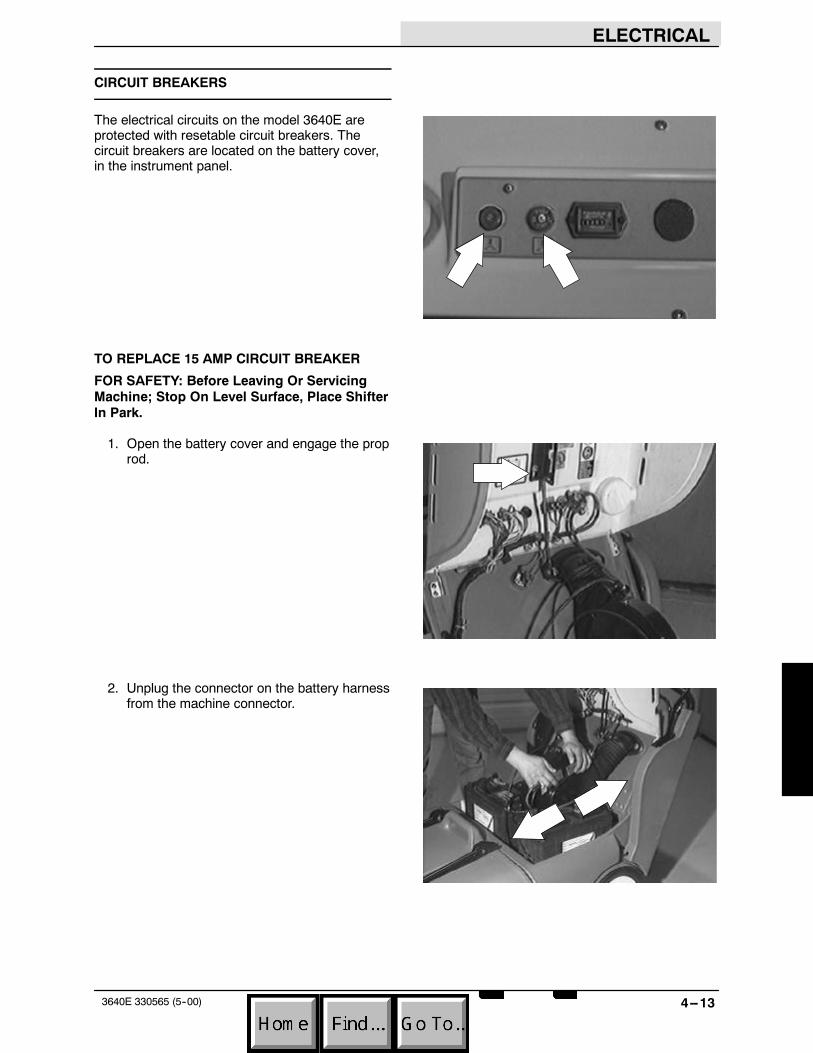
ELECTRICAL
4--133640E 330565 (5--00)
CIRCUIT BREAKERS
The electrical circuits on the model 3640E areprotected with resetable circuit breakers. Thecircuit breakers are located on the battery cover,in the instrument panel.
TO REPLACE 15 AMP CIRCUIT BREAKER
FOR SAFETY: Before Leaving Or ServicingMachine; Stop On Level Surface, Place ShifterIn Park.
1. Open the battery cover and engage the proprod.
2. Unplug the connector on the battery harnessfrom the machine connector.

ELECTRICAL
4--14 3640E 330565 (5--00)
3. Locate the 15 amp circuit breaker on the leftside of the cover. Remove the rubber boot.
4. Disconnect the wires leading to the back ofthe circuit breaker.
5. Remove the metal lock ring from the back ofthe circuit breaker. Remove the circuitbreaker.
6. Install the new circuit breaker (with thecorrect 15 amp rating) in the mount hole.Install the lock ring and rubber boot.
NOTE: The mount hole in the battery cover is ”D”shaped. Make sure to install the circuit breaker inthe correct orientation.
7. Reconnect the wires to the back of the newcircuit breaker. See schematic in thissection.

ELECTRICAL
4--153640E 330565 (5--00)
8. Plug the battery harness connector into themachine connector.
9. Close the battery cover. Start the machineand check the new circuit breaker for properoperation.

ELECTRICAL
4--16 3640E 330565 (5--00)
TO REPLACE 50 AMP CIRCUIT BREAKER
FOR SAFETY: Before Leaving Or ServicingMachine; Stop On Level Surface, Place ShifterIn Park.
1. Open the battery cover and engage the proprod.
2. Unplug the connector on the battery harnessfrom the machine connector.
3. Locate the 50 amp circuit breaker on the leftside of the cover.
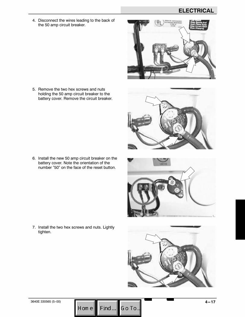
ELECTRICAL
4--173640E 330565 (5--00)
4. Disconnect the wires leading to the back ofthe 50 amp circuit breaker.
5. Remove the two hex screws and nutsholding the 50 amp circuit breaker to thebattery cover. Remove the circuit breaker.
6. Install the new 50 amp circuit breaker on thebattery cover. Note the orientation of thenumber ”50” on the face of the reset button.
7. Install the two hex screws and nuts. Lightlytighten.
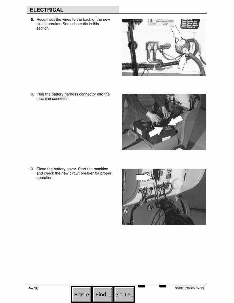
ELECTRICAL
4--18 3640E 330565 (5--00)
8. Reconnect the wires to the back of the newcircuit breaker. See schematic in thissection.
9. Plug the battery harness connector into themachine connector.
10. Close the battery cover. Start the machineand check the new circuit breaker for properoperation.

ELECTRICAL
4--193640E 330565 (5--00)
TO REPLACE MAIN CONTACTOR
FOR SAFETY: Before Leaving Or ServicingMachine; Stop On Level Surface, Place ShifterIn Park.
1. Open the battery cover and engage the proprod.
2. Unplug the connector on the battery harnessfrom the machine connector.
3. Locate the main contactor on the front of thefilter wall, behind the main drive motor.
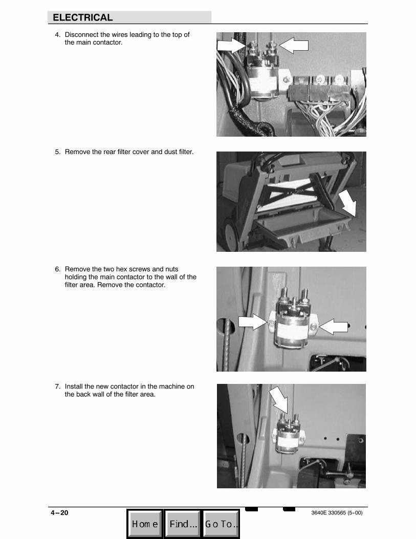
ELECTRICAL
4--20 3640E 330565 (5--00)
4. Disconnect the wires leading to the top ofthe main contactor.
5. Remove the rear filter cover and dust filter.
6. Remove the two hex screws and nutsholding the main contactor to the wall of thefilter area. Remove the contactor.
7. Install the new contactor in the machine onthe back wall of the filter area.

ELECTRICAL
4--213640E 330565 (5--00)
8. Install the two hex screws and nuts. Firmlytighten.
9. Reconnect the wires to the top of the newmain contactor. See schematic in thissection.
10. Plug the battery harness connector into themachine connector.
11. Close the battery cover. Start the machineand check the new main contactor for properoperation.

ELECTRICAL
4--22 3640E 330565 (5--00)
TO REPLACE ELECTRICAL RELAY
FOR SAFETY: Before Leaving Or ServicingMachine; Stop On Level Surface, Place ShifterIn Park.
1. Open the battery cover and engage the proprod.
2. Unplug the connector on the battery harnessfrom the machine connector.
3. Locate the relay block on the back wall,behind the main drive motor.
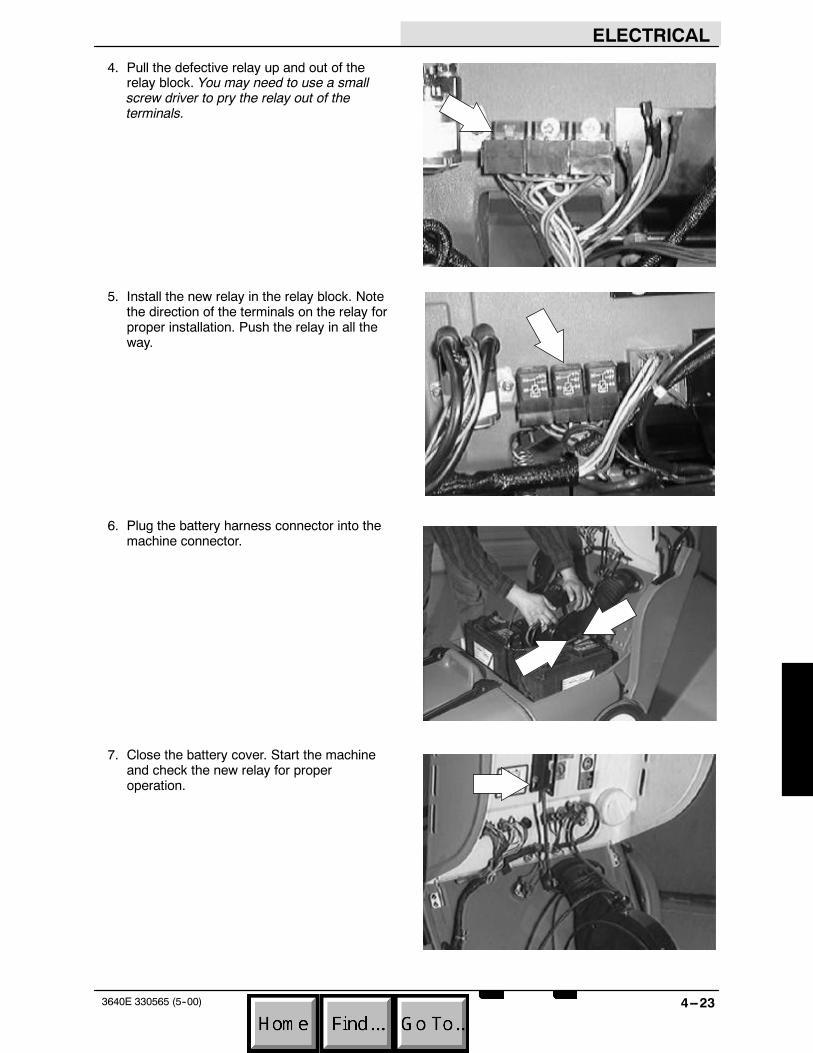
ELECTRICAL
4--233640E 330565 (5--00)
4. Pull the defective relay up and out of therelay block. You may need to use a smallscrew driver to pry the relay out of theterminals.
5. Install the new relay in the relay block. Notethe direction of the terminals on the relay forproper installation. Push the relay in all theway.
6. Plug the battery harness connector into themachine connector.
7. Close the battery cover. Start the machineand check the new relay for properoperation.

ELECTRICAL
4--24 3640E 330565 (5--00)
ELECTRIC MOTORS
The electrical motors on the model 3640E aredesigned to run on 24 volt battery power. Themotors included are the main drive motor, shakermotor, and side brush motor(s). The main drivemotor supplies power to the transaxle, vacuumfan, and main brush drive. The shaker motor hasan eccentric weight on the shaft that causes thefilter area to move when the motor rotates. Theside brush motor(s) are attached to right anglegear boxes that drive the side brush whenactivated.
TO REMOVE MAIN DRIVE MOTOR
FOR SAFETY: Before Leaving Or ServicingMachine; Stop On Level Surface, Set ParkingBrake.
1. Open the battery cover and engage the proprod.
2. Unplug the connector on the battery harnessfrom the machine connector.

ELECTRICAL
4--253640E 330565 (5--00)
3. Remove the battery in front of the main drivemotor.
4. Disconnect the wires leading to the twostuds on the main drive motor.
5. Loosen the adjustment screw on thevacuum fan. Let the vacuum fan drop downand remove the V--belt from the motorsheave.
6. Slip the flat drive belt off the motor sheave.

ELECTRICAL
4--26 3640E 330565 (5--00)
7. Remove the right side drive wheel assembly.See TO REMOVE REAR TIRE instructionsin the CHASSIS section.
8. Remove the tension on the main brush drivebelt and slip it off the motor sheave.
9. Remove the main brush from the machine.See TO REPLACE MAIN BRUSHinstructions in the SWEEPING section.
10. Remove the two front motor mount bolts.Access this hardware by going into thebrush wrap area and locating the twohardware dimples in the roof of the frame.
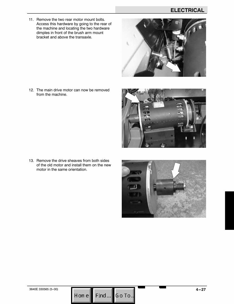
ELECTRICAL
4--273640E 330565 (5--00)
11. Remove the two rear motor mount bolts.Access this hardware by going to the rear ofthe machine and locating the two hardwaredimples in front of the brush arm mountbracket and above the transaxle.
12. The main drive motor can now be removedfrom the machine.
13. Remove the drive sheaves from both sidesof the old motor and install them on the newmotor in the same orientation.

ELECTRICAL
4--28 3640E 330565 (5--00)
TO INSTALL MAIN DRIVE MOTOR
FOR SAFETY: Before Leaving Or ServicingMachine; Stop On Level Surface, Set ParkingBrake.
1. Position the new drive motor on the mountplate.
2. Install the two front motor mount bolts.Access this hardware by going into thebrush wrap area and locating the twohardware dimples in the roof of the frame.
3. Install the two rear motor mount bolts.Access this hardware by going to the rear ofthe machine and locating the two hardwaredimples in front of the brush arm mountbracket and above the transaxle.

ELECTRICAL
4--293640E 330565 (5--00)
4. Reinstall the main brush in the machine. SeeTO REPLACE MAIN BRUSH instructions inthe SWEEPING section.
5. Install the main brush drive belt over thesheave on the right side of the motor. SeeTO REPLACE MAIN BRUSH DRIVE BELTinstructions in the SWEEPING section.
6. Reinstall the right side drive wheelassembly. See TO INSTALL REAR TIREinstructions in the CHASSIS section.
7. Reinstall the flat transaxle drive belt over thesheave on the left side of the drive motor.See TO REPLACE FLAT DRIVE BELTinstructions in the CHASSIS section.

ELECTRICAL
4--30 3640E 330565 (5--00)
8. Install the vacuum fan V--belt over thesheave on the left side of the motor. See TOTENSION VACUUM FAN V--BELTinstructions in the SWEEPING section.
9. Reconnect the wires on the two studs on themain drive motor. See schematic in theELECTRICAL section.
10. Reinstall the front battery in the machine.
11. Plug the battery harness connector into themachine connector.
12. Close the battery cover. Start the machineand check the new main drive motor forproper operation.
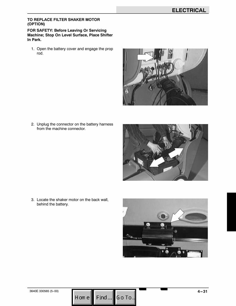
ELECTRICAL
4--313640E 330565 (5--00)
TO REPLACE FILTER SHAKER MOTOR(OPTION)
FOR SAFETY: Before Leaving Or ServicingMachine; Stop On Level Surface, Place ShifterIn Park.
1. Open the battery cover and engage the proprod.
2. Unplug the connector on the battery harnessfrom the machine connector.
3. Locate the shaker motor on the back wall,behind the battery.

ELECTRICAL
4--32 3640E 330565 (5--00)
4. Disconnect the electrical plug leading to theshaker motor.
5. Remove the hex screws holding the shakermotor mount bracket to the frame bracket.Remove the shaker motor from the machine.
6. Loosen the two set screw holding the weightto the motor shaft. Slide the weight off andinstall it on the new motor in the sameorientation. Firmly tighten the set screws.
7. Install the new shaker motor in the machine.Position it on the frame bracket and installthe mount bracket. Tighten the hex screwsto 18 -- 24 Nm (15 -- 20 ft lb).

ELECTRICAL
4--333640E 330565 (5--00)
8. Plug the new shaker motor into the mainelectrical harness. See schematic in thissection.
9. Plug the battery harness connector into themachine connector.
10. Close the battery cover. Start the machineand check the new shaker motor for properoperation.
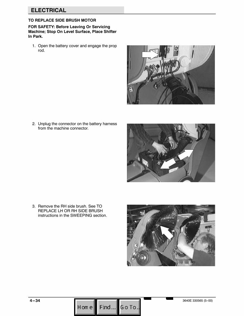
ELECTRICAL
4--34 3640E 330565 (5--00)
TO REPLACE SIDE BRUSH MOTOR
FOR SAFETY: Before Leaving Or ServicingMachine; Stop On Level Surface, Place ShifterIn Park.
1. Open the battery cover and engage the proprod.
2. Unplug the connector on the battery harnessfrom the machine connector.
3. Remove the RH side brush. See TOREPLACE LH OR RH SIDE BRUSHinstructions in the SWEEPING section.

ELECTRICAL
4--353640E 330565 (5--00)
4. Un--plug the RH side brush motor from themain electrical harness.
5. Remove the four hex screws holding theside brush motor and gear box to themachine frame.
6. Remove the side brush motor and gear boxfrom the machine.
7. Position the new side brush motor and gearbox in the machine. Line up the mount holesin the machine frame with the mount holesin the side brush motor.
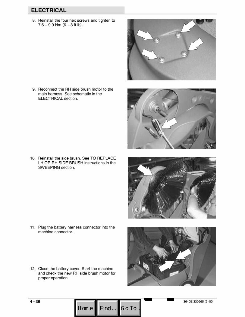
ELECTRICAL
4--36 3640E 330565 (5--00)
8. Reinstall the four hex screws and tighten to7.6 -- 9.9 Nm (6 -- 8 ft lb).
9. Reconnect the RH side brush motor to themain harness. See schematic in theELECTRICAL section.
10. Reinstall the side brush. See TO REPLACELH OR RH SIDE BRUSH instructions in theSWEEPING section.
11. Plug the battery harness connector into themachine connector.
12. Close the battery cover. Start the machineand check the new RH side brush motor forproper operation.

ELECTRICAL
4--373640E 330565 (5--00)
TO REPLACE SIDE BRUSH SWITCH
FOR SAFETY: Before Leaving Or ServicingMachine; Stop On Level Surface, Place ShifterIn Park.
1. Remove the filter cover from the rear of themachine.
2. Remove the handle stop bracket from theupper/left side of the filter compartment.
3. Pull up on the two handle locks and movethe handle assembly to its lowest position.

ELECTRICAL
4--38 3640E 330565 (5--00)
4. Remove the three flat screws holding thecover plate to the inside of the right sidehandle tower. Remove the cover plate fromthe machine.
5. Remove the hardware and pull the brushhandle mount plate away from the rightplastic handle.
6. Mark and disconnect the wires leading to theside brush switch.
7. Remove the two screws and nuts holdingthe switch to the brush handle mount plate.Remove the side brush switch from themachine.
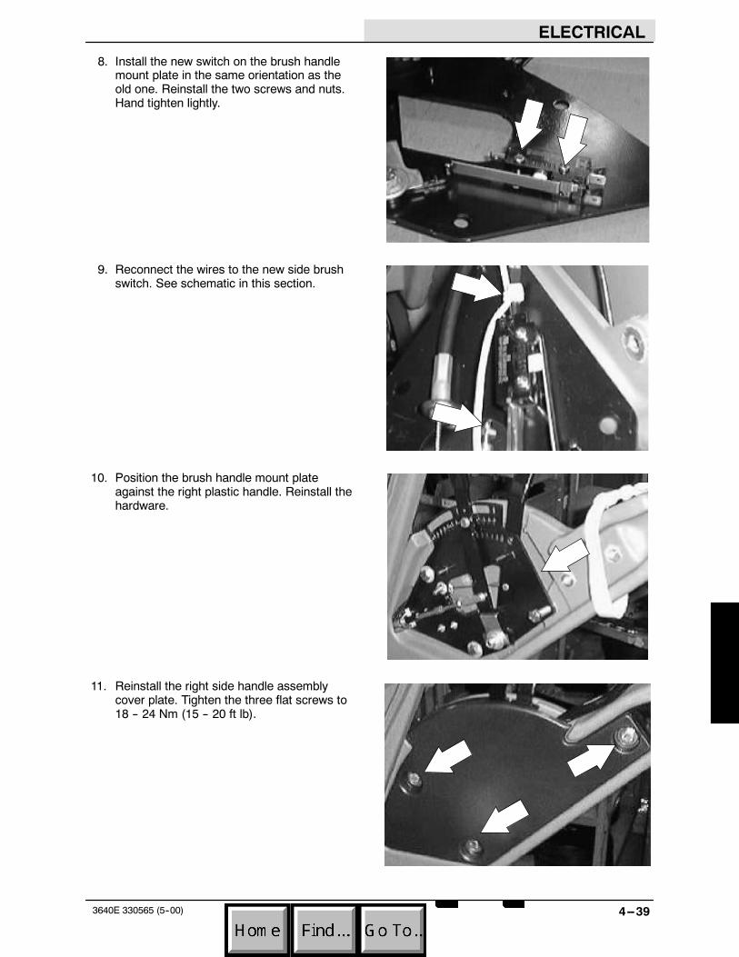
ELECTRICAL
4--393640E 330565 (5--00)
8. Install the new switch on the brush handlemount plate in the same orientation as theold one. Reinstall the two screws and nuts.Hand tighten lightly.
9. Reconnect the wires to the new side brushswitch. See schematic in this section.
10. Position the brush handle mount plateagainst the right plastic handle. Reinstall thehardware.
11. Reinstall the right side handle assemblycover plate. Tighten the three flat screws to18 -- 24 Nm (15 -- 20 ft lb).

ELECTRICAL
4--40 3640E 330565 (5--00)
12. Move the handle assembly up to one of thefour adjustment holes.
13. Reinstall the filter cover.
14. Reinstall the handle stop bracket.
15. Start the machine and check the side brushfor proper operation when the handle isplaced in the down position.

ELECTRICAL
4--413640E 330565 (5--00)
ELECTRIC MOTOR AMP DRAW CHART
F MAIN MOTOR " APPROX. 6 DC AMPS
F MAIN MOTOR W/ FAN ON -- MAIN BRUSHUP
" APPROX. 26 DC AMPS
F SIDE BRUSH MOTOR (NO LOAD) " APPROX. 1.5 DC AMPS
F SIDE BRUSH MOTOR (FREE FLOAT ONURETHANED CONCRETE)
" APPROX. 2 DC AMPS
F ENTIRE MACHINE (BRUSH IN FREEFLOAT ON URETHANED CONCRETE)
B
F 1 ST GEAR " APPROX. 32 DC AMPS
F 2 ND GEAR " APPROX. 34 DC AMPS
F 3 RD GEAR " APPROX. 38 DC AMPS
F REVERSE " APPROX. 33 DC AMPS
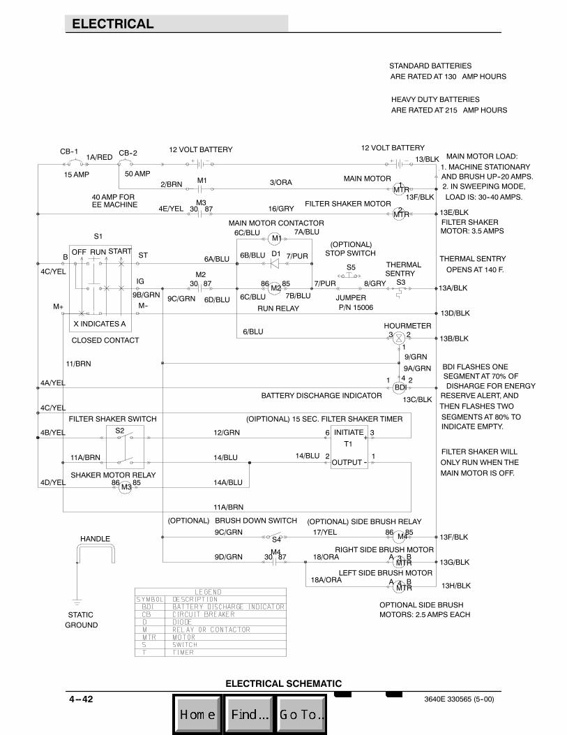
ELECTRICAL
4--42 3640E 330565 (5--00)
12 VOLT BATTERY
11A/BRN
BA18/ORA13G/BLK3
MTR
FILTER SHAKERMOTOR: 3.5 AMPS
2
4A/YEL
6/BLU
9B/GRN
4E/YEL
HANDLE
OPTIONAL SIDE BRUSHMOTORS: 2.5 AMPS EACH
T1
BDI FLASHES ONESEGMENT AT 70% OFDISHARGE FOR ENERGY
RESERVE ALERT, ANDTHEN FLASHES TWOSEGMENTS AT 80% TOINDICATE EMPTY.
13F/BLK
6C/BLU
6C/BLU6D/BLU
13H/BLK
13F/BLK
13C/BLK
13B/BLK
13D/BLK
13A/BLK
13E/BLK
4C/YEL
3/ORA2/BRN
JUMPERP/N 15006
--
8730
8730
30 87
8586
8586
MAIN MOTOR CONTACTOR
SHAKER MOTOR RELAY
RUN RELAY
M3
BATTERY DISCHARGE INDICATOR
THERMAL
S3M2
9D/GRN
9C/GRN
11A/BRN
X INDICATES A
CLOSED CONTACT
6B/BLU6A/BLU
1
8/GRY
18A/ORA
17/YEL
16/GRY
14/BLU FILTER SHAKER WILLONLY RUN WHEN THEMAIN MOTOR IS OFF.
BA
S4
9/GRN
9A/GRN11/BRN
M2
4 2
7/PUR
4B/YEL
7A/BLU
7B/BLU
7/PUR
4D/YEL
15 AMP
CB--1
9C/GRN
14A/BLU
S2
4C/YEL
M1
RIGHT SIDE BRUSH MOTOR
STANDARD BATTERIESARE RATED AT 130 AMP HOURS
HEAVY DUTY BATTERIESARE RATED AT 215 AMP HOURS
FILTER SHAKER MOTOR
3
1
D1
40 AMP FOREE MACHINE
THERMAL SENTRYOPENS AT 140 F.
12 VOLT BATTERY
STOP SWITCH
(OPTIONAL) SIDE BRUSH RELAY
+
BRUSH DOWN SWITCH
M4
1A/RED
4MTR
LEFT SIDE BRUSH MOTOR
INITIATE
(OPTIONAL)
MAIN MOTOR
3
MTR
14/BLU 1
SENTRY
STATICGROUND
13/BLK
ST
M3
S1
BDI
86
(OPTIONAL)
S5
50 AMP
B
M--
OUTPUT
MAIN MOTOR LOAD:1. MACHINE STATIONARYAND BRUSH UP--20 AMPS.2. IN SWEEPING MODE,LOAD IS: 30--40 AMPS.
2
M4
6
M1
OFF
MTR
12/GRN
2
FILTER SHAKER SWITCH
85
M+
CB--2
HOURMETER
IG
STARTRUN
(OIPTIONAL) 15 SEC. FILTER SHAKER TIMER
1
ELECTRICAL SCHEMATIC
ELECTRICAL
4--433640E 330565 (5--00)
TROUBLESHOOTING
The troubleshooting charts that follow areorganized so they lead you through the circuits.They include flow charts and instructions for youas to where to insert your test instruments.

ELECTRICAL
4--44 3640E 330565 (5--00)
DOES M1 CONTACTS CLOSE AFTERTURNING THE KEY SWITCH TOSTART AND THEN TO RUN ?
CHECK FOR BATTERY VOLTAGEBETWEEN ANY 9/GRN WIREAND ANY 13/BLK WIRE WITHTHE KEY SWITCH IN THE ONPOSITION
IS THERE BATTERYVOLTAGE BETWEENANY 4/YEL WIREAND 8/GRY ?
BATTERYVOLTAGE CHECK FOR BATTERY VOLTAGE
BETWEEN 1A/RED AND 13/BLKWIRE
MAIN MOTORTROUBLESHOOTING
0 VOLTAGE
MAIN MOTOR DOES NOT START
RESET ORREPLACE CB2
CHECK FOR BATTERY VOLTAGEBETWEEN ANY 4/YEL AND ANY13/BLK WIRE
BATTERYVOLTAGE 0 VOLTAGE
RESET ORREPLACE CB1HOLD THE KEY SWITCH IN THE
START POSITION AND CHECKFOR BATTERY VOLTAGE BE-TWEEN ANY 6/BLU AND ANY13/BLK WIRE
0 VOLTAGE
REPLACE THEKEY SWITCH
BATTERYVOLTAGE
0 VOLTAGE
REPLACE THETHERMAL SENTRY
BATTERYVOLTAGE
IS THERE BATTERY VOLTAGEBETWEEN ANY 4/YEL WIREAND ANY 7/PUR WIRE ?
0 VOLTAGE
RESET THE STOP SWITCHIF SO EQUIPPED ORCHECK TO SEE IF THEJUMPER CONNECTOR ISINSTALLED PROPERLY
BATTERYVOLTAGE
DOES THE M1 CONTACTORAND M2 RELAY PULL IN ?
NO
REPLACE M1 ANDOR M2
YES
0 VOLTAGE
REPLACE THEKEY SWITCH
BATTERYVOLTAGE
NO
REPLACE M2YES
CONTINUED ON NEXT PAGE...

ELECTRICAL
4--453640E 330565 (5--00)
CHECK MOTOR--- ---REPAIROR REPLACE
CONTINUED FROM PREVIOUS PAGE
IS THERE BATTERY VOLTAGEBETWEEN 3/ORA AND ANY13/BLK WIRE AFTER THE KEYSWITCH IS STARTED AND INTHE RUN POSITION ?
0 VOLTAGE
BATTERYVOLTAGE
REPLACE M1

ELECTRICAL
4--46 3640E 330565 (5--00)
FILTER SHAKERTROUBLESHOOTING
FILTER SHAKER WILL NOT OPERATE
BATTERYVOLTAGEREPLACE THE
FILTER SHAKER SWITCH
CHECK FOR BATTERY VOLTAGEBETWEEN ANY 4/YEL AND ANY 14/BLUWHEN THE KEY SWITCH IS OFF WHILEPRESSING THE SHAKER MOTOR SWITCH
CHECK FOR BATTERY VOLTAGEBETWEEN ANY 4/YEL AND ANY11/BRN WITH THE KEY SWITCHIN THE OFF POSITION
CHECK FOR BATTERY VOLTAGEBETWEEN ANY 4/YEL AND ANY13/BLK
SHAKEROK
CHECK FOR BATTERY VOLTAGEBETWEEN ANY 2/BRN AND ANY13/BLK
DOES THE FILTER SHAKERMOTOR RUN FOR 15 SECONDSAFTER THE SHAKER MOTOR SWITCHIS PRESSED WHEN THE KEY SWITCHIS IN THE OFF POSITION ?
NOYES
NO
YES
IS THE KEY SWITCH INTHE OFF POSITION ?
TURN THE KEYSWITCH TO THE OFFPOSITION
DOES THE FILTERSHAKER WORK NOW ?
SHAKEROK
DOES THE FILTER SHAKERMOTOR RUN WHILEPRESSING THE FILTERSHAKER SWITCH ?
NO
YES
NO
YES
REPLACE THE TIMER
0 VOLTAGE
RESET ORREPLACE CB1
0 VOLTAGE
RESET ORREPLACE CB1
BATTERYVOLTAGE
BATTERYVOLTAGE
0 VOLTAGE
REPLACE THEKEY SWITCH
BATTERYVOLTAGE
0 VOLTAGE
REPLACE THE SHAKERMOTOR RELAY
DONE
DONE

We Need Your Help...As part of Tennant’s Zero Defects Program, we want to know about errors you havefound or suggestions you may have regarding our machine manuals. If you find anerror or have a suggestion, please complete this postage-paid form and mail it to us.Thank you for helping us make zero defects a way of life at Tennant.
Manual No. Rev. No. Publish Date PageMachine - Report Error - Suggestion
Name DateCustomer NumberCompanyAddressCity/State/Zip Code
Tapehere Foldalongdottedlines
NOPOSTAGENECESSARY
IFMAILEDINTHE
UNITEDSATES
BUSINESSREPLYMAIL FIRSTCLASSMAILPERMITNO.94MINNEAPOLIS,MN
POSTAGEWILLBEPAIDBYADDRESSEE
TechnicalPublications#15701NorthLilacDriveP.O.Box1452Minneapolis,MN55440--9947
TENNANTCOMPANY

We Need Your Help...As part of Tennant’s Zero Defects Program, we want to know about errors you havefound or suggestions you may have regarding our machine manuals. If you find anerror or have a suggestion, please complete this postage-paid form and mail it to us.Thank you for helping us make zero defects a way of life at Tennant.
Manual No. Rev. No. Publish Date PageMachine - Report Error - Suggestion
Name DateCustomer NumberCompanyAddressCity/State/Zip Code

Tapehere Foldalongdottedlines
NOPOSTAGENECESSARY
IFMAILEDINTHE
UNITEDSATES
BUSINESSREPLYMAIL FIRSTCLASSMAILPERMITNO.94MINNEAPOLIS,MN
POSTAGEWILLBEPAIDBYADDRESSEE
TechnicalPublications#15701NorthLilacDriveP.O.Box1452Minneapolis,MN55440--9947
TENNANTCOMPANY