bauer global dam services€¦ · dam safety is bauer’s utmost priority at every phase of the...
TRANSCRIPT
BAUERGlobal Dam Services

2
ContentRehabilitation and Upgrade Dams
• Center Hill Dam, USA ............................................... 4• Sylvenstein Dam, Germany ....................................... 5
New Dams
• Diavik Diamond Mine, Canada .................................. 6• Jannah Dam, Lebanon ............................................. 7• Shuakhevi HPP, Georgia ........................................... 8• Bagatelle Dam, Mauritius .......................................... 9• Punatsangchhu-I Dam, Bhutan ............................... 10• Punatsangchhu-II Dam, Bhutan .............................. 11
Competences
• Construction Methods ............................................ 12• Applications ............................................................ 13• Equipment and Techniques ..................................... 14• Design .................................................................... 16• Concrete ................................................................. 17
Responsibility
• Quality Management ............................................... 18• HSE Management System ...................................... 19
Peribonka Hydroelectric Development, Canada

3
For more than 30 years, BAUER Spezialtiefbau GmbH, together with its subsidiaries, has been successful in the fi eld of design and execution of cut-off walls for dam re-habilitations, upgrades of existing dam structures, new dams and cofferdams. Such expertise recommends our involvement already at planning stages.
Our core competencies include different types of con-crete barrier walls through alluvium and embedded into fresh rock to depths of more than 150 m — more than 200 m are feasible at particular projects. Grout-ing, mixed-in-place as well as ground improvement are available to meet the project requirements.
Dam safety is Bauer’s utmost priority at every phase of the project management. Technological developments and experience in barrier wall constructions facilitate the preparation of specialist designs.
BAUER Spezialtiefbau GmbH offers its clients expert staff and state-of-the-art technology to develop plan-ning concepts for the emerging hydro energy market and provides excellent service, experience and inno-vation in ground engineering techniques necessary for dam construction. The company’s strengths are in-house resources facilitating tailor-made world-class solutions for projects around the globe, with the goal to deliver safely, on time and on budget.

4 Rehabilitation and Upgrade Dams
The Center Hill Dam Foundation Re-mediation project is located on the Caney Fork River about 96 km east of Nashville, Tennessee. The Center Hill Dam was constructed in the late 1940s to produce electricity and assist in flood control. In 2007, the United States Army Corp of Engineers (USACE), classified this dam as Dam Safety Action Classification (DSAC) I priority, the highest classification for remediation urgency. The USACE de-cided immediately to reduce the lake pool level until remediation could be completed. The USACE determined that the foundation under the earthen embankment needed remediation due to karst features in the limestone bedrock. The foundation remediation phase of the works completed by Bauer are arguably the most critical work to ultimately remove Center Hill Dam’s high risk status. The essence of the foundation remediation project was to construct a concrete cut-off wall to be used as a seepage barrier.
The project consisted of two major features of work:
• approximately 9,900 m² of encase-ment wall and
• approximately 20,500 m² of barrier wall.
The encasement wall has a nominal wall thickness of 2.25 m through the embankment, extending from the crest of the dam down to a minimum of 0.6 m into the foundation bedrock. The purpose of the encasement wall was to protect the embankment from collapse during excavation of the barrier wall in the event of drilling fluid loss during the barrier wall excavation
Center Hill Dam, USAthat penetrated deep into the karstic bedrock needing the remediation.
The encasement wall was excavated in 3.2 m long panels reaching depths of over 60 m. Each primary panel was pre-excavated using a hydraulic grab mounted on a BAUER MC 96 duty-cy-cle crane. Due to the overlap of the panels, the length of the secondary panel pre-excavation was consid-erably shorter and therefore was performed by the BG 50, the most powerful drilling rig made available by Bauer at that time. After pre-exca-vation, the panel was fully excavated using a BC 50 cutter mounted on the BAUER MC 128. Bauer’s B-Tronic system in conjunction with the use of advanced instrumentation and the steering capabilities of the cutter al-lowed the excavation at depth to be well below the contractual tolerances of 0.25 % panel verticality and six degrees panel rotation, despite locally adverse conditions of a steeply an-gled soil-rock interface. The encase-ment wall was constructed from May 2013 through February 2014.
The concrete barrier wall was con-structed through the center of the encasement wall extending down into the foundation bedrock for total depth of up to approximately 95 m. It was designed by the USACE as a hybrid wall consisting overlapping panels with additional piles overlapping the panel joints to achieve a minimum wall thickness of 0.6 m over the full depth. Based on the ability of the Bauer hy-drocutter to excavate the hard rock and maintain excellent verticality, a value engineering proposal was ac-cepted by the client to eliminate the additional piles at the panel joints for
the barrier wall construction. Based on the excellent geometric performance by Bauer, the constructed barrier wall minimum thickness is 0.7 m with an average thickness of 0.83 m, exceed-ing the minimum USACE requirement and providing additional value to the project. The barrier wall was exca-vated with a pair of 830 mm wide BC 40 cutters mounted on the MC 96 and MC 128. The concrete strength of the excavated encasement wall averaged around 35 MPa while the foundation bedrock strengths were up to 210 MPa. The barrier wall was constructed from March 2014 through March 2015.

5Rehabilitation and Upgrade Dams
Sylvenstein Dam, GermanyIn the course of 2012 – within a con-struction period of eight months from spring to autumn – Bauer installed a diaphragm wall with a depth of 70 m and a thickness of 1 m. The installa-tion of the concrete cut-off wall was the fi rst step in a three-phase mea-sure to retrofi t the dam. The client, Bayerisches Staatsminis terium für Umwelt und Gesundheit (Bavarian Ministry for the Environment and Health), was represented by the Water Board at Weilheim, Bavaria which had the responsibility for the execution. The Sylvenstein Dam, built between 1954 and 1959, has now been reinforced by the cut-off wall and further with a state-of-the-art reporting and controlling system for leakage water after having run for more than 50 years. Originally, the main task of the dam was to aug-ment the low water level of the Isar, meanwhile the focus has turned on mitigating strong fl oods for the ripar-
Bernhard Lederer, Bauoberrat (Respon-sible Authority) from the Bayerisches
Staatsministerium für Umwelt und Gesundheit (Bavarian Ministry for the
Environment and Health)
“Following the successful completion of Bauer´s part of the project, we would like to express our perfect satisfaction with the means and methods in which Bauer has performed on the project.”
lamellas embedded in rock approximately0.3 m
ians.Thus, the rehabilitation was also a precaution against the follow-up of possible climate changes and has proven during the fl oods of 2013 to be a major key to preventing fl ooding in Bad Tölz and Greater Munich. Sylven-stein Dam being 42 m of height and 180 m of length is based on a 100 m deep erosion trench in the main dolo-mite fi lled with detrital of the river. This
trench was sealed by several rows of injection grouting using clay-cement during the construction of the dam. The slim central sealing core consists of a soil-concrete (gravel, fi ne sand, silt with bentonite) with up and down-stream fi lters of moraine gravel. Now, a two-phase diaphragm wall was installed as new sealing element. Its position in the core is shifted slightly downstream of the dam axis. By exe- cuting several investigation drillings up to a depth of 140 m into the dam subsoil it was determined how deep the diaphragm wall had to be. The diaphragm wall had to reach a depth of up to approximately 70 m below the dam crest (achieving suffusion stabili-ty) cutting off seepage paths in the alternating layers of gravel and rock sediments and in the partly permeable old underground sealing. Starting from the 180 m long dam crest Bauer in-stalled the concrete cut-off wall having a total area of 10,000 m². Preparation works were executed with a grab in the upper part of the trench. Then, the diaphragm wall was installed, deploy-ing a BAUER BC 40 trench cutter with a base carrier MC 128, up to a depth of 70 m also embedding the wall later-ally into very hard rock.
B13 to Lenggries B307 to Tegernsee

6
The Diavik mine located approximate-ly 220 kilometers south of the Arctic Circle and 300 kilometers by air from Yellowknife, the territorial capital, is operated by Diavik Diamond Mines Inc., a member of the Rio Tinto Group. A deep cut-off wall was required for the 2.2 km perimeter dike so that the fourth kimberlite pipe, designated A21 and located under the waters of Lac de Gras, can be open-pit mined. A combination of different foundation engineering techniques was required to construct the proposed cut-off wall structure safely, effi ciently, and within environmental regulatory limits. The location of the mine presented special challenges, enabling works due to low temperatures only between May and October. Logistics was another major challenge, as large transports are only possible during an eight week window during the winter when the ice road to the mine is open. As a result, the proj-ect had to be completed in two stages in 2016 and 2017.
The foundation works started with the vibro densifi cation of the fi lled dike body along the proposed cut-off wall alignment. The actual bed-rock below the fi lled dike body and the underlying till was sealed with a grout curtain (works executed: drilling, water pressure testing and grouting) to nearly 60 m depth. The fi nal Cutter-Soil-Mixing (CSM) cut-off wall had to be installed through the densifi ed dike into the geolog-ical till-material deposited above the bedrock. More than 23,000 m pre-drilling in advance of the CSM works was executed to ensure em-bedment of the 23 m deep CSM cut-off wall into the till material contain-ing cobbles and boulders. More than
New Dams
Diavik Diamond Mine, Canada
Nik Auerboeck, Construction Manager A21 project
“Bauer’s performance and adherence to schedule despite geological chal-
lenges allowed dewatering on time as planned. Dike performance monitored up to April 2018 shows performance
to design.”
19,000 m² of CSM wall were installed along the dike perimeter utilizing this foundation technique, whereas the shallower connection points at each end of the dike were open excavated and fi lled with similar slurry material. The works on the cut-off wall were completed with jet grouting (pre-drill-ing and jetting) to safely close the gap between the bottom of the already in-stalled CSM element and the installed lower grout curtain. Quality control provisions included standard material testing and verifi cation drilling to prove the quality and integrity of the installed cut-off wall. The latter one was also surveyed and as-built drawings were produced to provide the necessary documentation and proof to our client.
During the subsequent dewatering process, various survey systems and geological instrumentation are in place to monitor the status of the dewater-ing and the dike structure itself. These allow the client not only to have im-portant live information such as the in-pond water level, the amount of water pumped, wall inclination and defl ection but also provides information on the sealing effect of the installed cut-off wall. In this regard, the feedback pro-vided by the client was very positive.

7New Dams
Jannah Dam, LebanonThe Jannah Dam, located on the Nahr Ibrahim River about 30 km north-east of Beirut, is designed as a massive arch gravity dam to store 38 million m3 of water to feed the areas of Byblos, Beirut and its suburbs. The maximum height of the dam above the foundation level is 162 m. Reach-ing the dam foundation level at sound rock requires an excavation to some 65 m below the original ground level and river elevation. The hydraulic control is ascertained by two cof-ferdams, at the upstream (U/S) and downstream (D/S) side, both con-structed on alluvial deposits. Plastic concrete cut-off walls, ranging about 50 m below the foundation of the cofferdams, prevent the water to fl ow under the cofferdams into the excavation pit. The slope of the deep excavation to the dam foundation level is supported by an arch-shaped bulk head. Employer is the ministry of
Luis Melo de Sampaio, Contractor´s Representative, Andrade Gutierrez
“The professional way in which the
Bauer team prepared and executed
the works was very well received.
Trial mixes and generally quality
management and control along
detailed method statement secured
highest standards of the quality for
the product. Bauer’s professional
approach towards Health Safety
Environment (HSE) was excellent.
The project was executed within
the agreed schedule but even less.”energy and water (Lebanon), our client was Andrade Gutierrez En-genharia S.A., consultant was Arte-lia Eau Environment. The installed plastic concrete cut-off walls provide the necessary vertical underground sealing below the cofferdams and extends over a length of 128 m (U/S) and 161 m (D/S). Approximately 9,500 m² cut-off wall with a nominal thickness of 1.0 m (U/S) and 0.8 m (D/S) was completed in December 2017 which included a percentage (12%) of excavation into moderately weathered and slightly weathered limestone (dolostone/dolomite) with UCS values up to 60 MPa, in order to reach the designed levels. The upstream and downstream cut-off walls were constructed in a relatively
steep valley with heterogeneous soil condition, consisting of fi ll, cobbles and boulders of limestone, basalt and chert, sand, clayey sand, sandy clay, gravel and weathered rock. The works were executed by utilizing one BAUER cutter unit BC 40.

8 New Dams
Shuakhevi HPP, GeorgiaThe foundation works were executed by BAUER Georgia Foundation Spe-cialists LLC at four locations in Geor-gia: Shuakhevi (Hydro Power House), Didachara (Reservoir), Chirukhistsqali (Weir) and Skhalta (Dam and Reser-voir). The Shuakhevi Hydro Power Plant (Skuakhevi HPP) is a run-of-the-river plant constructed in the auton-omous republic of Adjara, Georgia. It is part of a three-step cascade on the river Adjaristskali, and will have an installed capacity of 185 megawatt. The plant will have the capacity for diurnal storage in two reservoirs. The 22 m high Skhalta dam with a 19.4-hectare reservoir and the 39 m high Didachara dam with a 16.9-hect-are reservoir allowing Shuakhevi HPP to store water for up to 12 hours.
Zeki Yilmaz, Deputy Project Manager, AGE Batum LLC.
“The work carried out the works in a very professional way, in particular the construction of the cut-off wall.
When there were issues or ques-tions related to the particular works,
Bauer was proactive in seeking a solution and correcting the problem or answering the questions. I also note that the issues were few and infrequent. Bauer‘s professional approach towards Health Safety
Environment (HSE) was excellent. The project was executed within the
agreed schedule.”
and pressure tunnel. The employer is Adjaristsqali Georgia LLC, our client was AGE Batum LLC and consultant/engineer was Mott MacDonald. The works for the Skhalta Dam were exe-cuted between September 2016 and February 2017. The execution of the works was pioneer work in Georgia, being the fi rst plastic concrete secant pile cut-off wall on dams and the fi rst plastic concrete application in specialized geotechnical works in the country. 133 nos. secant piles with a nominal diameter of 1,500 mm and 500 mm intersecting between adja-cent piles were executed between October 2016 and February 2017 for the dam. Average depth amounted to 26.5 m; the longest pile depth was 34.3 m. A total of 3,526 linear m of piling was installed using a BAUER BG 28 with a BV 1500 oscillator. As specifi ed, piles at the abutments had to be installed at least 1 m into the competent rock. Other piles were de-signed to be embedded into the coarse alluvium, a stratum below a 2 m thick clay
layer. All pile depths and rock/alluvium levels were checked and confi rmed by inspectors from the consultant. A rope inclinometer device was used to assure overcut at each pile for wall continuity within the designed toler-ances. The toughest part was working during heavy winter conditions. The works for the Shuakhevi Hydro Power House Construction were executed in four stages between March 2014 and January 2015. In Stage 1 the so-called Upper cut-off wall, an unreinforced Secant Pile Wall with a nominal diam-eter of 880 mm, a quantity of 226 nos. piles with a maximum pile length of 20 m and a total drilling length of 3,355 linear m were constructed. Stage 2 the so-called Lower cut-off wall, includes the execution of a reinforced-concrete Secant Pile Wall with a nominal diame-ter of 1,180 mm, a quantity of 162 nos. piles, with a maximum drilling depth of 15,8 m, and a t total drilling length of 1,715 m. During Stage 3 and Stage 4 temporary ground anchors and foun-dation piles were executed.
Three main tunnels are to be con-structed on the Shuakhevi project; the 5.8 km Chirukhistsqali to Skhalta transfer tunnel, the 9.1 kilometres, Skhalta to Didachara transfer tunnel and the 17.8 km Shuakhevi headrace

9New Dams
Bagatelle Dam, MauritiusThe Bagatelle Dam project is located on the Terre Rouge River, about 20 km southeast of Port Louise and is a new dam reservoir used as a water reten-tion system for the regional drinking water supply. The installed plastic concrete cut-off wall provides the nec-essary vertical underground sealing below the earthen embankment dam section for a new water reservoir and extends over a length of 2.4 km. The cast-in-situ plastic concrete cut-off wall has a nominal wall thickness of 800 mm throughout the entire length, but was divided into three main sec-tions (Left Bank, Central Part and Right Bank) as defi ned in the technical specifi cations mainly due to the strong variation of the local geology. Approx-imately 57,000 m² cut-off wall was completed in May 2015 which includ-ed a large percentage (20,000 m²) of excavation through moderately weath-ered and slightly weathered basalt in order to reach the designed toe levels. The average excavation depth was 24 m with the maximum depth reach-
Wang Peng, Project Manager from China International Water & Electric
Corp.
„The quality of the work was fi rst class and accepted by the Engi-
neer. When there were issues, the site team was very proactive in
seeking a solution and correcting the problem. After uncovering the complete top of cut-off wall our physical inspection reinforced
the test results, confi rming that you have delivered a high quality
product.“
ing up to 44 m. Within the Central Area up to 28 m hefty and partly very hard basalt layers had to be excavated to reach the specifi ed toe level of the cut-off wall. To overcome the differ-ence in elevation of more than 12 m from the Central Area to the Left Bank and the Right Bank specifi c Bauer measuring devices were used assuring the specifi ed overlap and cut-off wall continuity. The works were executed by utilizing up to three BAUER BC 40 cutter units and two grab units over a construction period of 14 months.

10 New Dams
Punatsangchhu-I Dam, BhutanThe Punatsangchhu-I Hydroelectric Powerplant project is located in the Southern Himalayas, about 80 km east of Bhutan’s capital Thimphu. The new dam reaches across the Punatsangchhu River, delimited by steep hills on both sides. For the excavation of the pit for the main dam construction, two temporary cofferdams were required upstream and downstream of the pit across the Punatsangchhu River bed, to seal off ground and river water ingress. The V-shaped river gorge is fi lled with het-erogeneous river deposits, predomi-nantly consisting of highly permeable sand-gravel packages, intercalated by cohesive layers. Boulders in sizes up to few meters also frequently occur. Bedrock reaches from exposed sur-face down to as deep as 93 m below actual working platform elevation, with a UCS strength of occasionally more than 100 MPa. These highly permeable non-cohesive soil layers needed to be sealed for the purpose of creating a seepage barrier under-neath the upstream cofferdam. After evaluation of different sealing methods, a two-phase cutter-excavated cut-off wall (COW) was selected as the most appropriate and reliable methodol-ogy for the construction of the deep sealing element. Pretreatment works were carried out by means of gravity grouting and tube-à-manchette grout-ing, to temporarily seal the open void soil layers and to fi x boulders and big cobbles, thus mitigating the risk of localised collapses of excavated COW trenches, and to minimize ma-terial overconsumption. Pretreatment reached down to as deep as 96 m below working platform. The cut-off wall was constructed using one BAUER DHG-C hydraulic grab, and two
BAUER BC 40 trench cutter units. The nominal width of the COW is 1.2 m with panel length of 2.8 m and depth down to a maximum of 93 m, always embedding a minimum of 0.6 m into the solid bedrock. The biggest chal-lenges hereby were cutting through the numerous boulders, and the em-bedment of the COW into the steeply inclined, partially vertically dipping bedrock contour. Amongst the tech-nical challenges for constructing a COW under such diffi cult geotechni-cal conditions, the site logistics were one of the most signifi cant issues: All machineries, equipment and tools had to be shipped to Kolkata/India, and then by road to the site, over narrow mountainous roads into a quite remote area. Despite all the challenges, Bauer managed to com-plete the project on time and to the full satisfaction of the client.
K. K. Gupta, Project Director from Larsen & Toubro Limited
“The general quality management and control along the detailed
method statement secured the high-est standards of quality for the final product and technical issues related to the execution of this Project were
attended by Bauer proactively.”

11New Dams
Punatsangchhu-II Dam, Bhutan
K. K. Sood, Project Manager from Jaiprakash Associates Limited
„BAUER were equipped with all professional ways for the team
preparedness and work execution and proactive in seeking a quick
solutions for the site issues, main-taining highest standards of quality for the product and the professional approach towards health, safety and environment (HSE) was excellent.“
The Punatsangchhu-II Hydroelec-tric project (1,020 MW) located 15 km down-stream of the 1,200 MW Punatsangchhu-I Hydroelectric Pow-erplant on Punatsangchhu River is spreading along Wangdue – Tsirang National Highway in Wangdue Pho-drang Dzonkhag of Bhutan in the Southern Himalayas, about 80 km east of Bhutan’s capital Thimphu. The project has been jointly promoted by Royal Government of Bhutan and the Government of India under the Royal Government of Bhutan policy to im-plement hydro power projects within the country. The present project is be-ing implemented through Punatsang-chhu-II Hydroelectric Project Authority (PHPA). For execution of the main dam, permeation grouting was pro-posed to be carried out at the up-stream and downstream cofferdams up to the rock level to create a cut-off in order to control the water seepage in the dam pit during the construction.The cut-off is shallower compared to the on at the Punatsangchhu-I project.
On March 2014, Jaiprakash Associ-ates Ltd. awarded Bauer the per-meation grouting works at the up-stream cofferdam. The length of the grout curtain for seepage barrier at the upstream cofferdam is 170 m. The U-shaped valley is fi lled with alluvium in the river bed; river borne material and gneiss or granit boulders with size up to few meters. The bedrock quarzo-feldspatic gneiss reaches from the exposed surface down to 30 m (on average) below actual working platform elevation. Three grout rows were installed to form the reliable per-meation grouting curtain wall, cement grouts (cement and bentonite) were used for the outer rows and environ-
mentally friendly gel grouts (sodium silicates and hardener) were used for the inner row. On May 2015, Bauer completed successfully the works. Approximately 35,000 linear meters have been drilled and grouted since the award in 2014. The works were execut-ed by utilizing two drilling units Klemm KR 806-2DB and 12 grout pumps over a construction period of 12 months.

12 Competences
Construction Methods
Secant Pile Wall – Concrete
Cutter-Soil-Mixing (CSM) Wall – Cement-Bentonite
The Bauer Cutter-Soil-Mixing (CSM) system combines the benefits of our cutter experience and the environmental and economic advantages of Mixed-in-
The Bauer Cutter-Soil-Mixing (CSM) system combines the benefits of our cutter experience and the environ-mental and economic advantages of
The classical type of positive cut-off wall for deep barriers in all types of geology is excavated by grab and/or hydro cutter to reach depths of more than 200 m and is typically embedded in bedrock as designed. The walls are constructed using primary and sec-ondary elements with element length
depending on safety, trench stability of the slurry supported excavations and given geology. The continuous walls are formed by overcut of prima-ries while constructing the secondary elements. The limited number of joints are serrated and cleaned as required for optimum interlocking.
Diaphragm Wall – Concrete
Grout Curtains – GroutGrout curtains are intended to reduce the seepage through discontinuities in the foundation rock (ICOLD Bulle-tin 119–2000). Different techniques of grouting are provided and chosen by experienced engineers to provide seepage mitigation in the foundation. Whether jet grouting or permeation
low pressure grouting is used de-pends on a number of factors to be discussed for the individual project based on specified tasks and the existent geology. Professional quality control and documentation supports the successful execution.
Mixed-in-Place (MIP) Wall – Cement-Bentonite
Positive cut-off walls constructed by overlapping/interlocking circular pri-mary and secondary elements are be-ing executed by hydraulic drilling rigs. The open boreholes are supported by either special segmental steel casings or by slurry. The number of joints is to
be considered for these generally eco-nomical types of walls. The relatively small size of equipment is predestined for smaller working platforms. The continuous walls are being installed in all types of geology including embed-ment into rock.
Mixed-in-Place (MIP) walls are formed by mixing the existent soils with cement or cement-bentonite slurry to form a durable continuous cut-off wall. Depths reached by this technique depend on the base carrier size and range between 20 m
to 25 m. Execution sequence with primary elements and overcutting secondary elements are typical and similar to diaphragm wall. The very economic Mixed-in-Place walls are used to improve existing levees and dikes since decades.
Mixed-in-Place technologies. The rope suspended technique is available to even larger depths than the economic Mixed-in-Place system with triple augers.

13Competences
Construction Methods Applications
The Bauer Cutter-Soil-Mixing (CSM) system combines the benefi ts of our cutter experience and the environmental and economic advantages of Mixed-in-
Place technologies. The rope suspend-ed technique is available to even larger depths than the economic Mixed-in-Place system with triple augers.
New Dams — Greenfi eld Projects
Bauer cut-off walls provide new op-portunities for investors and designersinvolved in Water Resource Develop-ment projects. When planning a newWater Resource Development project,one of the major obstacles is fi nding alocation with suitable geological andhydrological formations for the projectincluding fulfi lling the environmental and social expectations. Bauer cut-off walls can be installed in any type of ground condition to provide a reliable, durable and impermeable (approxi-mately 1x10⁻⁸ m/sec.) system which ensures effi ciency, durability, stability and safety for your project. Thus, the Bauer cut-off wall makes selection of the project site that bit easier. Bauercut-off walls convert the existing ground conditions to meet your de-sign requirements, at a location of your choice. The ability to install safe walls in remote areas enables you to meet the environmental and social requirements of dams towards public interests.
Design and ConstructionStage 1
temporary diversiontemporary diversion
new dam
new dam
foundation treatment if required
proposed permanentcut-off wall
proposedcut-off wall
proposedcut-off wall
permanentcut-off wall
if required if required
Design and ConstructionStage 1
Cut-off wall in operationStage 2
Excavation in operationStage 2
Cofferdams for New Embankment Dam founded on alluvium
Cofferdams for excavation pits for New Concrete Dam founded on rock
Existing Dams — Upgrade, Rehabilitation and Repair Projects
Upgrade Design and ConstructionStage 1
Rehabilitation Design and ConstructionStage 1
Upgrade in operation“Increased dam safety and storage capacity”
Stage 2
Rehabilitation in operation“Increased dam safety and storage capacity”
Stage 2
Upgrade of Existing Dam(heightening)
Mitigate Seepages bydurable Concrete Barriers
As part of dam safety program, dam owners, municipal and state authori-ties and private parties conduct regular reviews of all their dams. Al-though the condition of a dam has not changed since it was built, reviews of the purpose or the design identify a need for upgrades to increase capac-ity or to enhance life span and dam safety which may be compromised due to hydraulic conditions or during major earthquakes.
Other existing barrier systems, for example those constructed with con-ventional grouting methods, over time and in the particular geology like Karst or alluvial/colluvial sediments, often fail to meet the degree of effi ciency and durability, as well as other per-formance specifi cations impairing the life span of the structure as required by the design and intended purpose.
temporarycofferdam
temporarycofferdam
temporarycofferdam temporary
cofferdam
upstream
downstream
temporarycofferdam
temporarycofferdam
proposed permanentcut-off wall
proposed permanentcut-off wall
permanentcut-off wall
permanentcut-off wall

14 Competences
Cutter and Grab
Bauer rotary drilling rigs on large dams are used to construct a secant pile wall or – in combination with diaphragm wall elements – a hybrid wall. The BG hydraulic drilling rigs like BG 28 or BG 40 are ideally suited for drilling cased or slurry-supported
boreholes with the kelly-system and special drilling tools as demanded by the individual geology on the project. The segmental steel casings for cased boreholes are installed by rotary drive or optionally by hydraulic oscillator powered by the drilling rig.
Rotary Drilling Rig
Bauer trench cutters and Bauer hy-draulic grabs are typically the lead equipment for the panel excavation for the execution of concrete cut-off walls.The centrepiece of the Bauer trench cutter system consists of a steel frame with two gearboxes attached at its base, which rotate in opposite direc-tion around their horizontal axis. Cutter wheels suitable for the pre-vailing ground conditions are mount-ed on the gearboxes. Selecting the most suitable type of cutter wheels (equipped with flat teeth, round shank chisels or roller bits) is essential for cutter progress which mainly depends on the geological conditions (particle size, density, abrasiveness, com-pressive strength, etc.). The accurate determination on the trench cutter for your project depends on the project ground conditions, the required trench width and wall depth. The ideal base carriers for Bauer trench cutter and mechanical or hydraulic grab equip-ment are BAUER MC 64, MC 96 and MC 128 duty-cycle cranes. The entire hydraulic power supply of the attached cutter/hydraulic grab is provided by the hydraulic systems of the MC duty- cycle cranes which have been special-ly designed for those applications.
Equipment and Techniques

15Competences
The open trenches of diaphragm wall elements are supported by slurry. During the preparation of bentonite slurry, the bentonite powder has to be mixed intensively with water. This is achieved by pump mixers or col-loidal mixers of the SCW/SK-series. Single-phase slurry mixes for cut-off slurry walls consisting of multiple components, such as rock powder, cement, bentonite and water, are pro-duced by Bauer mixers as well. Bauer desanding plants are developed spe-
Small Diameter Drilling Rig
Mixed-in-Place
Cutter-Soil-Mixing
Bauer Mixed-in-Place (MIP) equipment is developed specifically for use in the overburden (granular, slightly cohesive soils). The entire hydraulic power for the rotary drives of the attached triple augers is provided by the hydraulic system of the base carrier which have been specially modified for those appli-cations. Base carriers like BAUER RG 18, RG 22, RG 25 or BG 40 are chosen as per the final depth to be reached.
Cutter-Soil-Mixing (CSM) originates from and uses components of the Bauer trench cutter technique. Cutter wheels break up the soil matrix and mix it with cement slurry to a homoge-neous soil-cement mortar. The system is applicable in various soil conditions - even in hard or layered strata. It is mainly used for the construction of cut-off and retaining walls.
Mixing and Desanding Unit
The main equipment for the drilling and grouting method on large dams are the Bauer hydraulic drilling rigs of the KLEMM KR 800-series. These modern and extremely compact rigs are particularly suitable for the differ-ent drilling applications:
• Rotary-, • Rotary drilling with down-the-hole hammer, • Rotary percussion-, • Overburden-, • Double head drilling rotary/rotary and
• Double head drilling rotary/rotary percussion
The drilling rigs will be fitted with hydraulic drifters of the Eurodrill HD- series, with different types of drill rods and drill tools to suit the geology and depth required for the individual pro-ject. After state-of-the-art controls over borehole deviation the grouting pro-cess will be executed. The accurate determination on grouting equipment (pump type, mixer, packer type, etc.) depends on soil conditions and the required grouting material.
cifically for the use with trench cutters to separate the cuttings from the slurry used to support the open trench and to transport the cuttings. The plants are characterized by the following fea-tures: modular construction throughout the entire plant unit and, therefore, the ability to match treatment capacity to soil type and cutter output capacity. Advantages: secondary circulation with desilter or centrifuge possible, short setting up and dismantling times and containerized transport dimensions.
16 Competences
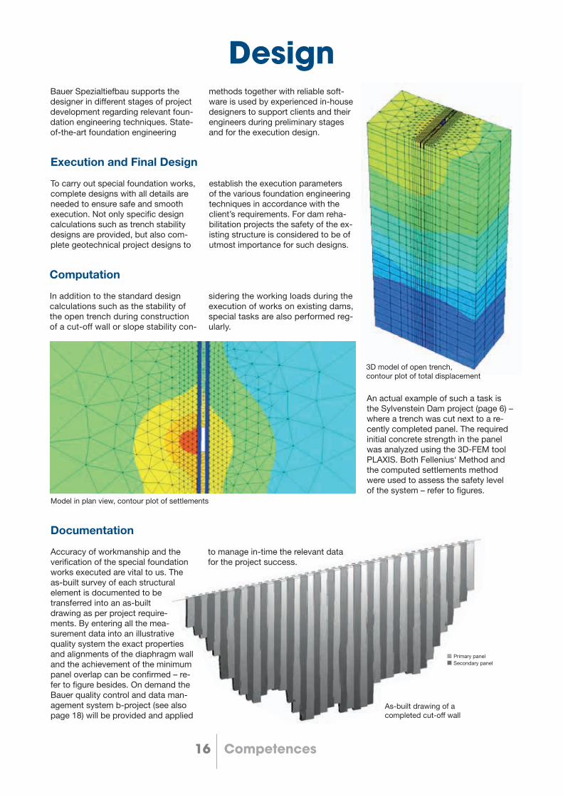
Bauer Spezialtiefbau supports the designer in different stages of project development regarding relevant foun-dation engineering techniques. State-of-the-art foundation engineering
methods together with reliable soft-ware is used by experienced in-house designers to support clients and their engineers during preliminary stages and for the execution design.
To carry out special foundation works, complete designs with all details are needed to ensure safe and smooth execution. Not only specific design calculations such as trench stability designs are provided, but also com-plete geotechnical project designs to
establish the execution parameters of the various foundation engineering techniques in accordance with the client’s requirements. For dam reha-bilitation projects the safety of the ex-isting structure is considered to be of utmost importance for such designs.
Execution and Final Design
In addition to the standard design calculations such as the stability of the open trench during construction of a cut-off wall or slope stability con-
sidering the working loads during the execution of works on existing dams, special tasks are also performed reg-ularly.
Computation
Accuracy of workmanship and the verification of the special foundation works executed are vital to us. The as-built survey of each structural element is documented to be transferred into an as-built drawing as per project require-ments. By entering all the mea-surement data into an illustrative quality system the exact properties and alignments of the diaphragm wall and the achievement of the minimum panel overlap can be confirmed – re-fer to figure besides. On demand the Bauer quality control and data man-agement system b-project (see also page 18) will be provided and applied
Documentation
An actual example of such a task is the Sylvenstein Dam project (page 6) – where a trench was cut next to a re-cently completed panel. The required initial concrete strength in the panel was analyzed using the 3D-FEM tool PLAXIS. Both Fellenius‘ Method and the computed settlements method were used to assess the safety level of the system – refer to figures.
3D model of open trench, contour plot of total displacement
Model in plan view, contour plot of settlements
Primary panelSecondary panel
Design
to manage in-time the relevant data for the project success.
As-built drawing of a completed cut-off wall

17Competences
ConcreteBauer Concrete Competency has been established and has been constantly progressing due to:
• In-house scientific research sup-ported through academic coop-eration with partner universities, in-vestigating and assessing materials’ influence on the installation process and their influence on the final, inte-gral quality of the wall or pile.
• BAUER Spezialtiefbau GmbH co- operates worldwide with various organisations to specify standards and regulations. Amongst others we participate in the following groups:
We are a member of the German delegation for the Technical Com-mittee TC288 of CEN in charge of European Standards for Execution of Special Geotechnical Works
(EN 1538 Diaphragm Walls). We were also a member of the
tremie concrete task group of the Piling and Foundation Specialists Federation (which compiled the “Guideline on Tremie Concrete for Deep Foundations” published in 2012 by the Concrete Institute of Australia).
Furthermore we have been chairing the joint Concrete Task Group of the EFFC, the European Foundation Contractors, and of the DFI, the Deep Foundation Institute (USA), established in January 2014. In
2018 the 2nd edition of the Guide to Tremie Concrete for Deep Founda-tion was released. It recommends to adjust the design and quality control of Tremie concrete in accordance to latest developments and introduces these results to the European and international market, applicable for the revision of the concrete speci-fications for the next generation of CEN standards.
• Consulting in operational works, hence giving project-specific advice in concrete design, raw materials and concrete testing as well as quality assessment, in all construction phases from planning, calculating or finally executing the dam rehabilitation project.
Bauer aims to support own projects in all matters and steps of materials’ use for deep foundation works. Regarding concrete for dam rehabilitation princi-pal demands have to be specified in order to proof both sufficient fresh and hardened concrete properties:
• Permeability and erodibility, both must, within defined ranges, ensure the demanded serviceability of the wall.
• According to Bauer’s experiences gathered in own research, stan-dards and consulting works the concrete, prior to its application in a project, must be properly de-
signed, specifically tested and optimized. For placing concrete in deep excavations, the fresh con-crete behavior must be understood and required properties must con-sequently be controlled throughout the concreting process.
• It is Bauer’s experience that the cut-off wall construction safety for both the ultimate and service limit state, in terms of its function as a water barrier, should not be based on the strength of the plastic con-crete used but on its deformation capacity in order to gain from the material‘s plastic properties.

18 Responsibility
Quality Management
Construction Quality Control (CQC) System Commitment Bauer is committed to deliver high quality products for all our projects.For each project we implement a project specific Construction Quality Control (CQC) System which aims to ensure a consistent, high quality standard of workmanship throughout all phases of the works. Our CQC Sys-tem intended to control and verify the works executed, is based on, amongst others, the following core fundamental quality principles:
• Ensuring the highest quality of works by establishing, monitoring, maintaining and updating quality control procedures. This is achieved by providing written instructions to govern quality control procedures and practices to clearly establish defined responsibilities and author-ities early in the project to ensure quality compliance;
• Compile accurate records of test results, certifications and other re- quired documentation which con-form to the project specific contrac-tual requirements and standards;
• Notifying the client‘s representative of deficiencies in quality and pro-posed corrective action, and ensuring that agreed corrective action is properly implemented;
• Providing qualified individuals who will be responsible for the man-agement and implementation of an agreed CQC program; and
• Providing high quality workmanship and project administration by imple-menting agreed transparent docu-mentation procedures.
Quality is the basis for the BAUER Group’s worldwide success and there-fore it is part of the key-focuses of the company. The confidence in the quality of our products, services and equipment gained throughout many years will be preserved and expanded to its optimum.
“Verified Quality is our most successful product. It is the key to success, today and tomorrow.”
Quality Strategy for Cut-off Walls
• Proper continuity of the entire wall
• Integrity of the cut-off wall concrete material placed
• Proper embedment of the wall into the defined strata
Quality Control Areas for Cut-off Walls
• Trench stability
• Slurry mixing and recycling
• Monitoring of supporting slurry
• Monitoring abnormalities, soil conditions and wear & tear
• Panel verticality and overcut verification
• As-built visualization
• Proper concrete mix design with quality products
• Concrete batching and testing
• Production analysis
• In-time documentation
Cutter Inclination System (CIS)
Future drilling projects will drill down to even greater depths. Furthermore, the requirements for compliance of verticality will increase. As the market currently offers only timeconsuming measurement methods, then neces-sity of a new or further developed measurement system is obvious. The Technical Services Department of BAUER Spezialtiefbau GmbH devel-oped a measuring system that meets such requirements - the DIS system. This system enables rapid and precise determination of borehole geometry by means of non-contact tachymetric survey. Reflectorless measurement of the rope on several layers allows for estimation of the rope‘s inclination up to the upper edge of terrain.
System Our quality management system is based on ISO 9001 and the relevant legal and industrial norms. All relevant processes of our company are methodically analyzed and docu-mented. The processes are aimed at increasing the product quality for the continuous improvement process and thus help to improve the customers’ and employees’ satisfaction levels. We use key figures to regularly check if the planned quality objectives have been achieved. Deviations are ana-lyzed and rectified in due time.
b-project Our data management system b-pro-ject is designed to store and organize information on special foundation projects. It allows us to track jobsite data and run reports on production data in a BIM (Building Information Modeling) compatible way.

19Responsibility
HSE Management SystemThe required Health, Safety and En-vironmental performance is achieved through the:
• BAUER Group’s Health, Safety and Environmental Management state-ment and guidelines
• Bauer Spezialtiefbau HSE System
• National and inter-national standards and guidelines
Compliance with the HSE policy, system and standards are mandatory and subject to periodic audit. In part-nership projects, Bauer Spezialtiefbau subsidiaries are required to encourage the partner to work to Bauer HSE standards and to implement an appro-priate HSE management system that will achieve the following goals:
• Reduced work-related accidents and illness
• Reduced costs associated with accidents and illness
• Improved performance through policies and procedures
• Compliance to the latest legislation
• Reduced risk of citations/penalties
• Improved company image by de-monstrating a commitment to man-age and minimize risks to employees, stakeholders and customers
The Bauer Spezialtiefbau HSE Man-agement System allows for a common approach to be adopted across all businesses. The key elements are out-lined below and are supported by the fundamental requirement:
• Leadership
• Commitment
• Involvement
Project specifi c HSE plans are devel-oped on these principles focusing on the individual demands of the project and the specifi c methods, techniques and equipment used.

BAUER Spezialtiefbau GmbHBAUER - Strasse 186529 Schrobenhausen, GermanyTel.: + 49 8252 97- 2440Fax: + 49 8252 [email protected]
905.
019.
2
10/
2018
The specifications and technical data are provided as indicative information only, with any errors and misprints reserved.