baymak lĐnyĐtomat plus domestic solid … plus...63 9810.0293 - rev.00 - 08/09/2008 2 baymak...
TRANSCRIPT
63 9810.0293 - Rev.00 - 08/09/2008
BAYMAK LĐNYĐTOMAT PLUS DOMESTIC SOLID FUEL BOILERS
INSTRUCTION AND OPERATING MANUAL
63 9810.0293 - Rev.00 - 08/09/2008
2
BAYMAK LĐNYĐTOMAT PLUS DOMESTIC SOLID FUEL BOILERS INSTRUCTION AND OPERATING
MANUAL
WARNING!
All local regulations, including those referring to national and European standards need to be complied with when installing the appliance.
Please read this manual carefully before you use the boiler. You will have the “Service Center Address Book” which include the information dealing with the authorised service center with this book.
The boiler’s initial operating must be done by Baymak authorised
service, otherwise the boiler will be out of warranty.
BAYMAK MAKĐNE SANAYĐ VE TĐCARET A.Ş.
Orhanlı Beldesi, Orta Mahalle Akdeniz Caddesi No:7 Tuzla / ĐSTANBUL
Tel: (0216) 304 20 44-304 10 88 (pbx) Fax: (0216) 304 20 13
http:// www.baymak.com.tr E-mail:[email protected]
63 9810.0293 - Rev.00 - 08/09/2008
3
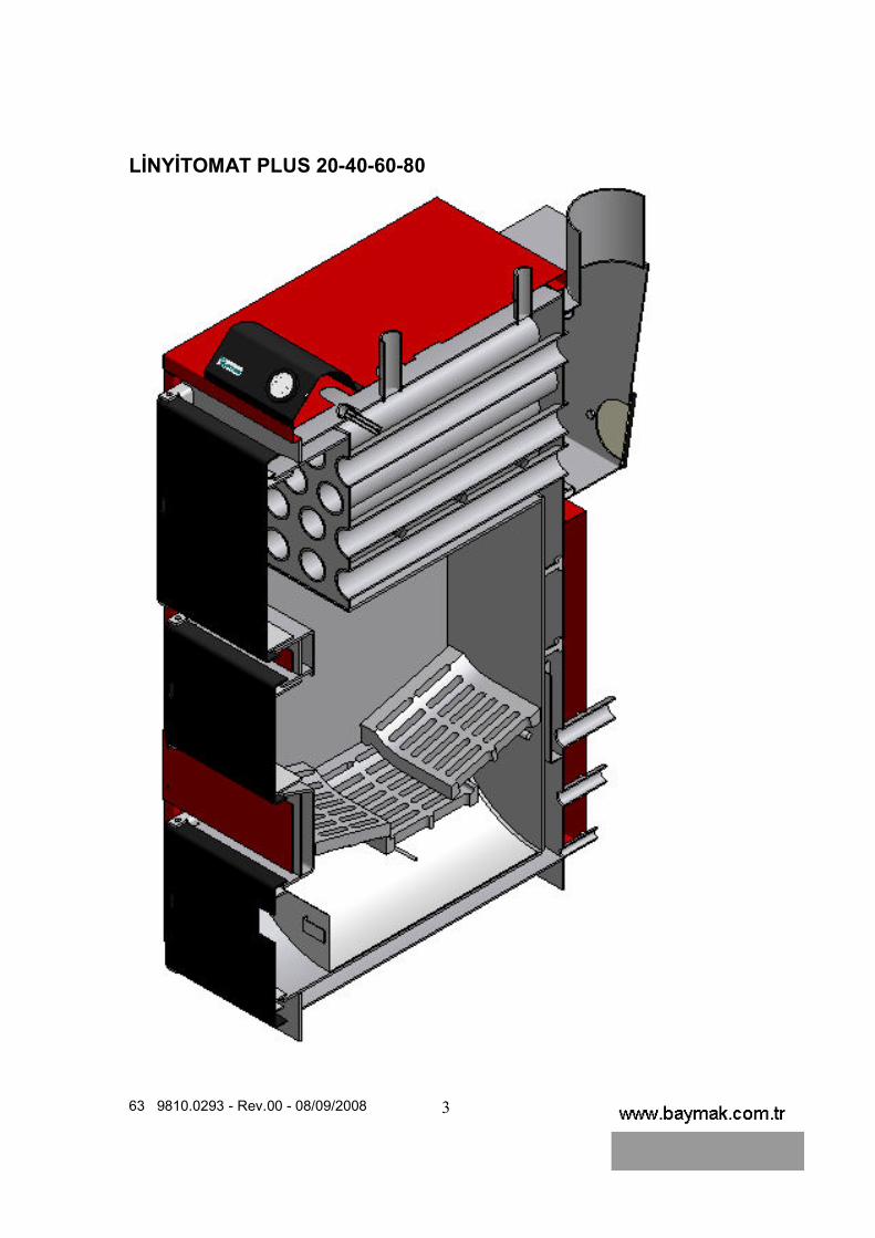
LĐNYĐTOMAT PLUS 20-40-60-80
63 9810.0293 - Rev.00 - 08/09/2008
4
63 9810.0293 - Rev.00 - 08/09/2008
5
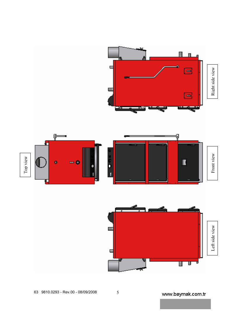
Top v
iew
Fro
nt vie
w
Rig
ht si
de
vie
w
Lef
t si
de
vie
w

63 9810.0293 - Rev.00 - 08/09/2008
6
1 1.)Boiler water temperature indicator 2.)Temperature adjustment thermostat 3.)Fan starting button 4.)Pump working button 5.)Manuel-0 Automatic Selection button 6.)Flue pipe cleaning door 7.)Coal loading door 8.)Ash cleaning door 9.)Flue gas box pipe 10.)Boiler water outlet pipe 11.)Expansion tank outlet pipe 12.)Boiler water inlet pipe 13.)Expansion tank outlet pipe 14.)Boiler filling and drainage pipe 15.)Fluegas box 16.)Fluegas box cleaning door 17.)Boiler top casing 18.)Boiler right side casing 19.)Boiler left side casing 20.)Boiler back casing 21.)Boiler front bottom casing 22.)Boiler front middle casing 23.)Door opening&closing handle 24.)Ash shaking&discharging handle 24.Kül silkeleme&boşaltma kolu 25.)Top door casing 26.)Middle door casing

63 9810.0293 - Rev.00 - 08/09/2008
7
Symbols in the manual
Danger! Negligence of this warning creates danger for your body and life
Electricshock danger! Negligence of this warning creates danger for your body and life due to electricshock.
Attention! Negligence of this warning creates danger for ambient health and device.
Warning / Info : You can find special information and advices here.
Reference to additional information in other documents.
General Safety Cautions All local regulations, including those referring to
national and European standards need to be complied with when installing the appliance.
Don’t use the appliance as an incinerator or any
other different way from which it has been conceived. Don’t use unsuitable or non-recommended fuels. Don’t use liquid fuels. Don’t make any unauthorized modification on the
appliance.

63 9810.0293 - Rev.00 - 08/09/2008
8
Use only replacement parts recommended by the manufacturer.
Danger! Please take into considirations the
cautions on the boiler. Wrong operation of the boiler causes serious damages.
Applications of first start-up, setting, maintenance
and cleaning must only be done by authorized service. When breakdowns occur in the heating system,
system must be shut down. Damaged components must be changed by authorized service stations.
The accesories in the system must be suitable to
technical rules, components in question must be approved by manufacturer relating to Baymak boiler.
Connections sealed with bolt paint must not be
pulled out by a person who is not expert or member of service! These seals prove that bolts which is necessary for perfect and safe operation has not been changed. If seals get damage, boiler will be out of warranty!
Alteration, structural cursory modifications and all
similar works are forbidden. These kind of modifications may be dangerous for people and cause damages on boiler. In case of neglagence of these subjects, boiler will be out of warranty.
Obstruction of holes of air ventilation and air relief
is dangerous and forbidden. Do not place easy explosive and ignitable
materials near to boiler.
Danger in case of gas smell! In case of existing gas smell, do not operate switches by electricity. Ventilate the room and shut down gas prevention mechanism. If the source of the smell can not be found, gas supplier administration must be informed.
Poisoning Danger! Do not drink heating system
water! Water is not clean due to precipitates.

63 9810.0293 - Rev.00 - 08/09/2008
9
Caution! Safety valve and air release line must be open everytime because of water discharge for safety. Safety valve must be checked occasionally. Safety valve must be installed onto boiler directly and there must not be any other valve or equipment. All used equipment must be in accordance with CE standards.
Electricshock Danger! Before protective hat and
pieces of cover are taken out, all electrical connections on boiler must be disassembled. Works that will be done when electric is on, must be carried on by authorized people after all necessary precuations are supplied.
Please read this manual before using the boiler. Start-up must be done by authorized service
station. Otherwise the boiler will be out of warranty.
Important Points for Mounting and Mounting Place
The appliance shall be installed on floors with an adequate load-bearing capacity. If an existing construction doesn’t meet this prerequisite, suitable measures (e.g. load distributing plate) shall be taken to achieve it.
The installation of the appliance need to provide access for cleaning the appliance, the flue gas connector and the chimney flue.
Caution! Subjects refering considerations during mountings related with operations of heating or a tank are below.
To prevent from water damages that will occure due to especially water leakages in tank, convenable precuations must be taken for mounting. Drain lines and safety system must be suitable and checked periodically during first start-up and operation.
Ambient where is boiler in must be dry and must not frost (between 0° and 45°).
Operations about supplying required air to burn the boiler and discharging waste gas must be in accordance with CE standards and local distrubition companies that is responsible from that region.
Place the boiler to a boiler room. Do not place the boiler to your bedroom!

63 9810.0293 - Rev.00 - 08/09/2008
10
Settle the boiler onto concrete base. Ambient where is boiler in should not be dusty and moist.
Caution! Waste gas way must be as short as
possible. Waste gas pipes must be installed as in slanting direction towards chimney and connections must have full imperviousness.
The chimney must be designed considering technical specifications determined in DIN 4705 and built according to DIN 18160.
*The boiler should be placed onto the concrete
base.
*The size of the concrete base is shown on the
table.
*After placing the boiler on to base, it should be
balanced from the ground surface.
B(Wide)
Concrete
base
Depth Wide Height
63 9810.0293 - Rev.00 - 08/09/2008
11
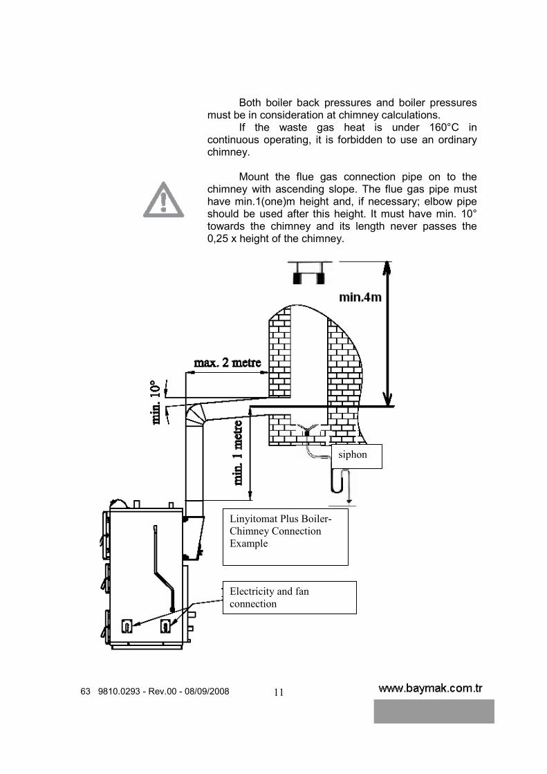
Both boiler back pressures and boiler pressures must be in consideration at chimney calculations.
If the waste gas heat is under 160°C in continuous operating, it is forbidden to use an ordinary chimney.
Mount the flue gas connection pipe on to the
chimney with ascending slope. The flue gas pipe must have min.1(one)m height and, if necessary; elbow pipe should be used after this height. It must have min. 10° towards the chimney and its length never passes the 0,25 x height of the chimney.
.
siphon
Linyitomat Plus Boiler-
Chimney Connection
Example
Electricity and fan
connection

63 9810.0293 - Rev.00 - 08/09/2008
12
Linyitomat Plus Boiler Model LP 20 LP 40 LP 60 LP 80
Flue Gas Pipe Connection Diameter(mm) Ø130 Ø150 Ø180 Ø200
Chimney must be isolated well to increase the combustion quality. You may use maximum two elbows between chimney and flue gas box.
Installation
You must take measures against rain or water
consisted as a result of condesnsing waste gases. The chimneys have to be comlied with national
and European Standards.
Caution! Mount an air relief device onto outlet pipe of boiler hot water. Air relief device must be installed by installator company in accordance with installation to the points where air may be exist on installation except boiler.
Carrying and transportation must be done together with original packaging material of device considering the marking on the boiler. Please protect the boiler against factors that can damage to packaging material and device.
Caution! Check the slants of boiler installation connetions with a water gauge. After slants have been done, there must not been any air in the system.
Caution! As the boiler works or in case of operation of the boiler without water, water must not be pumped to the boiler directly. The boiler water must be gave at low temperature when the boiler does not operate. Otherwise system may come to harm. Cold water must not be pumped into hot boiler. Otherwise the boiler will be out of warranty and manufacturer company is not responsible for physical and sipiritual damages.
63 9810.0293 - Rev.00 - 08/09/2008
13
Location of the device must be done in accordance with CE,national standards and local regulations to ambients that air current exists.
The open expansion tank must be connected to the boiler. The closed expansion tanks are very dangeorus for solid fuel boilers. If closed expansion tank is used, the boiler will be out of warranty. The diameter of the open expansion tank connection pipe must be same with the boiler connection pipe’s. The open expansion tank connection pipes must be steel installation pipe not plastic. The usage of the plastik installation pipe on expansion tanks is very dangerous and in this case the boiler will be out of warranty.
To fill and drain water to the boiler, you must mount a valve.
You should isolate all the installation pipes to prevent heat loss.
Make the boiler electricity connection to the grounding plug.
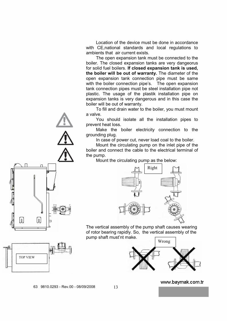
In case of power cut, never load coal to the boiler. Mount the circulating pump on the inlet pipe of the
boiler and connect the cable to the electrical terminal of the pump.
Mount the circulating pump as the below: The vertical assembly of the pump shaft causes wearing of rotor bearing rapidly. So, the vertical assembly of the pump shaft must’nt make.
TOP VIEW
Right
Wrong

63 9810.0293 - Rev.00 - 08/09/2008
14
There must be absolutely a bypass line on the inlet pipe of the boiler. In case of the power cut, you can secure the safety of the boiler and installation.
Physical life of the boiler is 10 years according to related laws. This period contains service and providing required spare part duration for executing the functions.
The boiler was produced in accordance with
EN 303-5.
Protection against corrosion
Caution! Combustion air must not contain elements that will cause to corrosion. As an example, these gases are water steams of solution and cleaning substances or gases in spray boxes.
Demands related with heating system water
To prevent the damages occured as a result of corrosion in installation, quality of heating water must be as good as drinking water. Unsuitable waters containing chemical additive substances or causing to corrosion must not be used.
Filling water for boiler and installation should not contain residues, contaminates and unwanted solid materials. These unwanted materials are very dangerous for the boiler and installation. If you have any doubt about the water pureness, you should mount a fitler on inlet of the filling valve.
The degrees of water hardness must not be
bigger than 20º F’den ( 1º F = Calsium carbonade @ 1 lt water) . ( Hard water ) If the degres of water hardness is bigger than 20º F, a water softening system absolutely must be used.
Bypass valve (It is closed in normal situation, it should be opened in case of power cut.)
Circulating
pump

63 9810.0293 - Rev.00 - 08/09/2008
15
In case of boiler failure which be caused by calsification, using hard and unsuitable water, the boiler will be out of warranty.
PROPERTIES OF LĐNYĐTOMAT PLUS BOILER
Ayarlanabilir baca klapesi ile yanma ayar kolaylığı
Sökülebilir davlumbaz ile temizlik ve bakım kolaylığı
Arka kaplamada bulunan kaya yünü ile yüksek izolasyon ve düşük ısıkaybı.
Kazan su girişi ile çıkışıarasında bulunan su dağıtma sacı sayesinde yüksek verim.
Hareketli ızgara sistemi sayesinde kül silkeleme ve kül boşaltma ile temizlik kolaylığı.
Đki amaçlı kül tepsisi ile hem kül boşaltma hem kömür yükleme kolaylığı.
Üç kapaklı ve mandallıtasarım sayesinde tam sızdırmazlık, kolay açılıp kapanma ve yükleme, boşaltma, temizlik kolaylığı.
Çift taraflı menteşe sistemi ile iki tarafa açılabilienkapaklar.
Gövde üzerinde bulunan50 mm alüminyum folyolu cam yünü ile yüksek ısıizolasyonu.
• The fan is mounted on Linyitomat Plus boiler to make combustion easy. The
fan and pump are controlled two ways: Automatic and manuel mode. At manual mode, the control of fan is maked by adjusting thermostat on control panel. The fan works, until the boiler water temperature reaches the selected temperature by adjusting thermostat. When it reaches to adjusted temperature, the fan stops automatically and when the boiler water temperature decreases 5°C, the fan starts working again. When the boiler water temperature reaches the selected temperature again, the fan stops and the cycle goes like this. When you select the automatic mode, the electronic thermostat activates the fan at the start
The boiler body is
covered 50mm thickness
glass wool with
aluminium folio.
Boiler doors with double
side opening hinge
system
Full sealing, easy
opening/closing,
loading/discharging due
to the 3 doors with the
latch system
Easy coal loading and ash
discharging with two
aimed ash tray.
Easy combustion control
with adjustable flue gas flap.
Easy cleaning and
maintenance with the
demountable flue gas box.
High insulation and low heat
loss by the rock wool in
back casing..
High efficiency by water
distributing plate between
inlet pipe and combustion
chamber.
Easy cleaning by ash
shaking and ash discharging
with moveable grid system.

63 9810.0293 - Rev.00 - 08/09/2008
16
of the working. When the temperature reaches 40°C, the pump starts working. When the boiler water temperature decreases and become 40°C, the control panel stops the pump and reaches to 30°C stops the fan.
• At Linyitomat 80 plus model boilers, when you don’t want to work fan, you
can switch the off button on the control panel. In this case the fan doesn’t work. You can have a good combustion without fan. It depends on the quality and thermal efficiency of coal.
• The fixable and adjustable flue gas flap system was designed to control combustion. Pulling the arm to yourself by the help of spring and pin, you will control the combustion. When the chimney draught is too high, you can throttle the flap to have a good combustion.
Fixable and adjustable flap
Turbulators
63 9810.0293 - Rev.00 - 08/09/2008
17
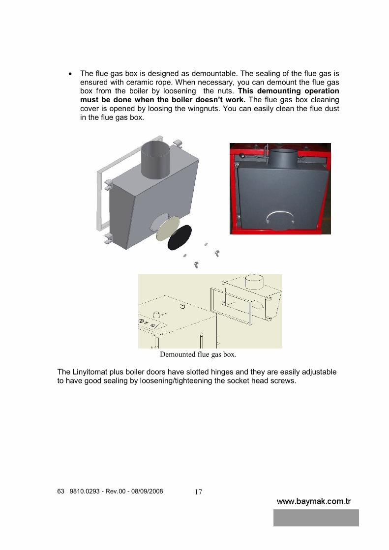
• The flue gas box is designed as demountable. The sealing of the flue gas is ensured with ceramic rope. When necessary, you can demount the flue gas box from the boiler by loosening the nuts. This demounting operation must be done when the boiler doesn’t work. The flue gas box cleaning cover is opened by loosing the wingnuts. You can easily clean the flue dust in the flue gas box.
Demounted flue gas box.
The Linyitomat plus boiler doors have slotted hinges and they are easily adjustable to have good sealing by loosening/tighteening the socket head screws.

63 9810.0293 - Rev.00 - 08/09/2008
18
Socket head screw Boiler left hinge
Flue gas
cleaning
door Boiler
right
hinge
• According to the replacement of the boiler to a boiler room, you can switch the opening direction of the door with the changing process right and left hinges by loosening socket head screws. The opening direction is adjusted clockwise direction at the factory.
• You can shake the ashes on the grids by pulling and pushing ash shaking arm little by little on the right side of the boiler. By pulling the arm to yourself, you can discharge the ashes into the ash tray or combustion chamber.

63 9810.0293 - Rev.00 - 08/09/2008
19
a)The arm is at normal position b)The arm is at ahead position c) The arm is at back position
• You can discharge the ash from the boiler and load the coal into the fire room with the ash tray which be put into bottom of the combustion chamber.
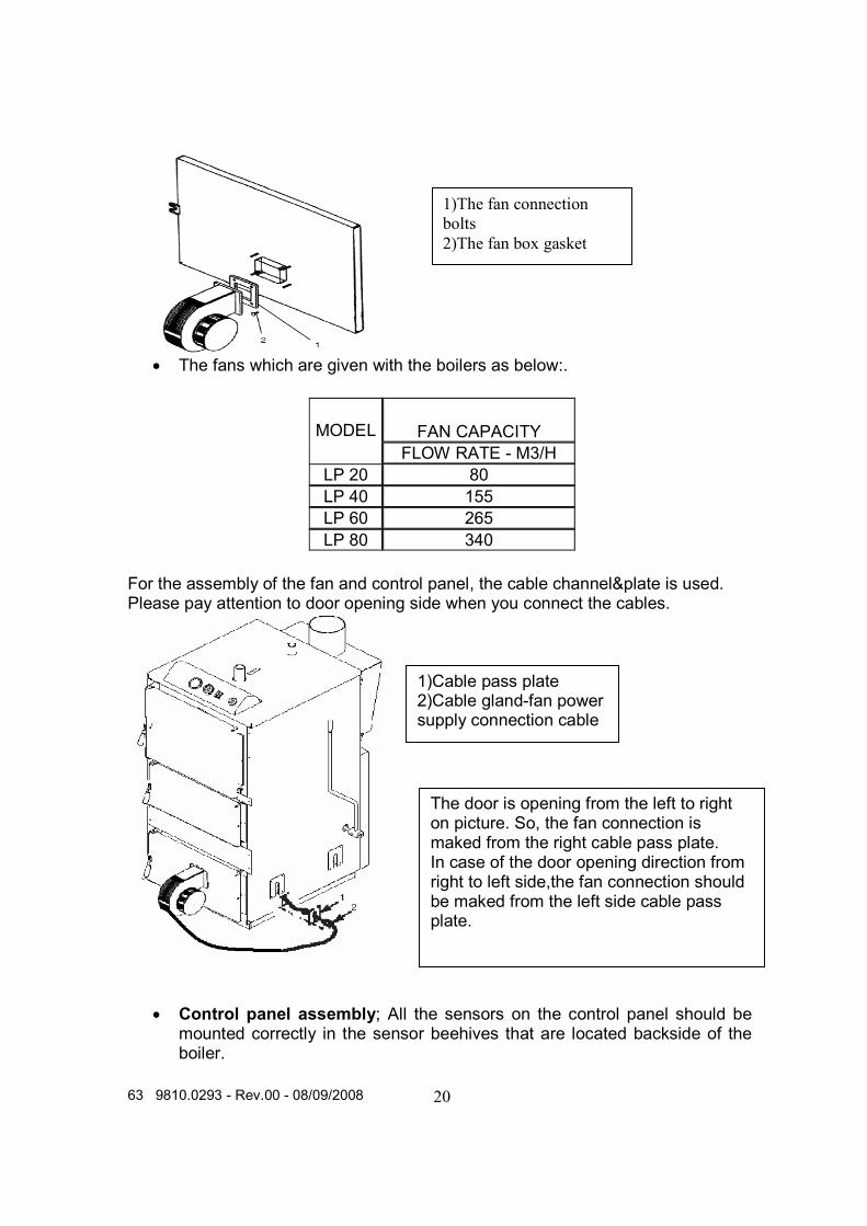
• The fan assembly; you must be sure that no air leakage by fixing the gasket between fan(you will find the fan in the combustion chamber, when you unpacked the boiler.) and the door with screws. The electricity connection must be comply with the electrical scheme.
Coal
loading
Ash
discharging
63 9810.0293 - Rev.00 - 08/09/2008
20
• The fans which are given with the boilers as below:.
FAN CAPACITY MODEL FLOW RATE - M3/H
LP 20 80 LP 40 155 LP 60 265 LP 80 340
For the assembly of the fan and control panel, the cable channel&plate is used. Please pay attention to door opening side when you connect the cables.
• Control panel assembly; All the sensors on the control panel should be mounted correctly in the sensor beehives that are located backside of the boiler.
1)The fan connection
bolts
2)The fan box gasket
1)Cable pass plate 2)Cable gland-fan power supply connection cable
The door is opening from the left to right on picture. So, the fan connection is maked from the right cable pass plate. In case of the door opening direction from right to left side,the fan connection should be maked from the left side cable pass plate.

63 9810.0293 - Rev.00 - 08/09/2008
21
• That is important and necessary for operating safely of the boiler • To be sure if the sensors mounted to correct place and fixed properly.
Control Panel
1. Boiler Thermostat Sensor 2. Boiler Thermometer Sensor 3. Boiler Safety Thermostat Sensor 4. Fasten sensor clip
63 9810.0293 - Rev.00 - 08/09/2008
22
LINYITOMAT PLUS BOILER BURNING INSTRUCTION
• Burning method changes according to size of coal. Coal quality and the characteristics of the burning, affect to the burning method and efficiency of the boiler
• Normal sized coals (Orange size), For first burning, fill some wood and wood part and ignite from lover side. This time the fan should be closed position and the ash cleaning door should be fully open, the other doors should be closed. After igniting, the ash cleaning door should be closed and loading door opened, 1/3 capacity of coal per excreted in the boiler (The average 5-20kg). After coal loading process, the fan can be on position. In this position even the fan off, burning can be started but it’s depending to the coal quality.
• You can choose the burning methods at above, according to the coal quality and statement of combustion.
• Loaded 1/3 capacity coal start to burning and begin to charcoals, the ash cleaning door to be opened and skewered and than to be made last loading.
• For the last loading, completely fill the boiler. During the burning, open the the ash cleaning door and skewer to the coal every 2-3 hour. Also open the coal loading door and reverse sunburned coal parts using a rabble. During the coal loading process to be sure if ON/OFF switch at OFF position. If it is not, turn it OFF
• It is important that fan’s electrical connections to be done right, otherwise the fan doesn’t work correctly and doesn’t give enough air into combustion chamber.
• Load the boiler with coal before the coal completely burn. (When the coals become completely charcoals) Operating the boiler in this way is more economic and more efficient.
• In the mornings, the ash cleaning door to be opened and skewered. After starting of the burning can be loaded coal. Before this process, the fan may be made Switch On.
• If coal loading was not enough in the previous evening or in the day coal level gets low, load some wood and after getting enough burning and load the enough coal. Otherwise if the coal loaded on the some sunburned coal, it causes to be flame turned off.
• The boiler should be cleaned at list once a week. Burning efficiency will get higher when used cleaned boiler.
• Don’t use cokes.
• Powder coal, and a very small with granular coal, For the first burning, fill to much wood and wood part and ignite them. (the ash cleaning door should be open).
• When the flame is grove enough, load 5-10 kg coal on the woods. Until coal and wood turn into charcoals, you should wait.
63 9810.0293 - Rev.00 - 08/09/2008
23
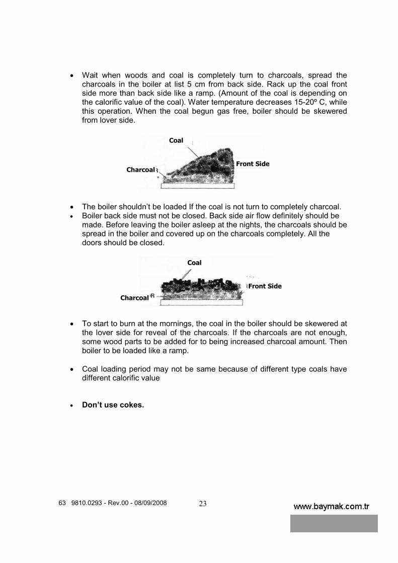
• Wait when woods and coal is completely turn to charcoals, spread the charcoals in the boiler at list 5 cm from back side. Rack up the coal front side more than back side like a ramp. (Amount of the coal is depending on the calorific value of the coal). Water temperature decreases 15-20º C, while this operation. When the coal begun gas free, boiler should be skewered from lover side.
• The boiler shouldn’t be loaded If the coal is not turn to completely charcoal. • Boiler back side must not be closed. Back side air flow definitely should be
made. Before leaving the boiler asleep at the nights, the charcoals should be spread in the boiler and covered up on the charcoals completely. All the doors should be closed.
• To start to burn at the mornings, the coal in the boiler should be skewered at the lover side for reveal of the charcoals. If the charcoals are not enough, some wood parts to be added for to being increased charcoal amount. Then boiler to be loaded like a ramp.
• Coal loading period may not be same because of different type coals have
different calorific value • Don’t use cokes.
Charcoal
Coal
Front Side
Charcoal
Coal
Front Side

63 9810.0293 - Rev.00 - 08/09/2008
24
LINYITOMAT PLUS BOILER TECHNICAL INFORMATION
• Boiler flue gas temperature could be change between 180-300ºC Under normal conditions. This value may be a little more at first burning. At the minimum power, it is 130-180ºC according to room temperature.
• For Linyitomat PLUS LP 20- 80
boiler water temperatures was limited like shown at the table.
• It is mandatory that the boiler return and out water temperature have to be limits that are given at the table.
• If the return water temperature low than at the table, an auxiliary pump have to be used.
• In case circulation pump doesn’t run, flame situation should be checked in the boiler. Level of coal should be check if the coal level is enough for increasing of the water temperature. In that case measure must be taken.
• Fuel loading mouth measurements A(mm) B(mm) LĐNYĐTOMAT 20 PLUS 330 203 LĐNYĐTOMAT 40 PLUS 430 210 LĐNYĐTOMAT 60 PLUS 430 220 B LĐNYĐTOMAT 80 PLUS 530 250 A
In case of lignite coal
usage
Min.Boiler water inlet temperature
oC50 oC
Min. Boiler water outlet temperature
oC60 oC
At 80-60ºC operating
tempearature Operating temparature range
Shunt pump
flow capacity
Calculating method of the auxiliary pump flow capacity For LP 80

63 9810.0293 - Rev.00 - 08/09/2008
25
• Capacities:
The capacities of the pumps used in Linyitomat plus boiler and the required capacity of open expansion vessels are as follows:
MODEL Capacity
kcal/h DAB
Circulating Pump Open Expansion Vessel
LĐNYĐTOMAT PLUS 20 20.000 VA 35/130 50 LT LĐNYĐTOMAT PLUS 40 40.000 VA 65/130 100 LT LĐNYĐTOMAT PLUS 60 60.000 A 50/180 XM 100 LT LĐNYĐTOMAT PLUS 80 80.000 A 56/180 XM 110 LT
PUMP TECHNICAL DETAILS
MODEL STEP REVOLUTIONS d/dak.
POWER W
CURENT CAPASITOR
Mf Installation
connection Electricity
connection 1 1440 44 0,2 2 1910 60 0,28 VA 35/130 3 2370 71 0,31
2 1 ½” G 1x230 V 50 Hz
1 1050 51 0,24 2 1460 78 0,35 VA 65/130 3 2100 102 0,45
2,5 1 ½” G 1x230 V 50 Hz
1 2297 168 0,80 2 2651 189 0,92
A 50/180 XM
3 2791 184 0,92 4 2” G
1x230 V 50 Hz
1 1394 224 1,00 2 2117 294 1,32
A 56/180 XM
3 2658 271 1,00 - 2” G
1x230 V 50 Hz
Model
Power

63 9810.0293 - Rev.00 - 08/09/2008
26
Capacity kcal/h 20.000 40.000 60.000 80.000 A(Height)(mm) 1095 1295 1343 1500 B(Width)(mm) 590 690 690 790 C(Depth)(mm) 735 880 1110 1260 D Chimney Diameter(mm) Ø130 Ø150 Ø180 Ø200 Boiler Inlet(Ø) 1" 1 1/4" 1 1/4" 1 1/2" Boiler Outlet(Ø) 1" 1 1/4" 1 1/4" 1 1/2" Expansion Inlet(Ø) 1" 1" 1" 1" Expansion Outlet(Ø) 1" 1" 1" 1" Fillling and Draining(Ø) 1/2" 1/2" 1/2" 1/2" Boiler Water Capacity (Lt) 70 107 162 200 Expansion Vessel Water Volume (Lt)
50 100 100 110
Circulating Pump(DAB) VA 35/130 VA 65/130 A 50/180 XM A 56/180 XM Weight(Kg) 255 377 492 641 Max.Operating Pressure (Bar)
3 3 3 3
Test Pressure (Bar) 4,5 4,5 4,5 4,5 Necessary Draught(mbar) Flue Gas Temperature at nominal heat output(ºC)
176,5 196,6 170 170
Flue gas mass flow at nominal heat output(kg/s)
0,02641 0,03307 0,04188 0,08433
Flue gas mass flow at minimum heat output(kg/s)
Mean content of CO at 10 O2 (%)
0,585 0,642 0,734 0,764
Water side resistance(mbar)
Nominal heat output for coal(kW)
22,5 46,15 69,22 93,11
Heat output range for coal(kW)
18-23 32-46 50-69 75-93
Boiler efficiency class 3 3 3 3 Boiler efficiency (%) 75,72 78,86 78,21 78,87 Combustion period at nominal heat output for coal(h)
4 4 4 4
Minimum water inlet/outlet temperature(ºC)
50/60 50/60 50/60 50/60
Setting range for the temperature controller(ºC)
60-85 60-85 60-85 60-85
Rated input power(W) 156 202 364 451 Rated voltage(V) 230 230 230 230 Rated frequency(Hz) 50 50 50 50

63 9810.0293 - Rev.00 - 08/09/2008
27
MODEL L L1 L2 B B1 B2 H H1 H2 F WEIGHT VA 35/130 130 98 60 104 78 26 124 75 49 1 ½” G 2,65KG VA 65/130 130 98 60 104 78 26 124 75 49 1 ½” G 2,65KG
A 50/180 XM 180 90 90 173 34 139 143 52 92 2” G 4,8 A 56/180 XM 180 90 90 173 34 139 143 52 92 2” G 4,8

63 9810.0293 - Rev.00 - 08/09/2008
28
The boiler can be operated whether automatically within electronic thermostat control or manually with user control.
1.)For automatic control; Switch the manuel-0-Otomatik button to otomatik position. The electronic thermostat control is enabled in this position. It controls the fan and pump according to the water temperature. At the start up, the electronic thermostat control make the fan works.When the water temperature is 40ºC, the pump starts working. When the water temperature starts to decreasing, it stops the pump at 40ºC and stops the fan at 30ºC.
IMPORTANT: In automatic working position, minimum one of the pump button or the fan button must be closed(0) to have a good working. 2.)For working manual operating; Switch the manuel-0-Otomatik button to manuel position. In this position, the fan and the pump are controlled theirself buttons. In both position(manual or automatic), the temperature adjustment is maked with the adjust thermostat. If the water temperature is over the set temperature, the adjust thermostat stops the fan.

63 9810.0293 - Rev.00 - 08/09/2008
29
AUTOMATIC
Electronic Control Board
Manuel-Automatic Control

63 9810.0293 - Rev.00 - 08/09/2008
30
Ele
ctri
city
connec
tion c
ircu
it s
chem
e

63 9810.0293 - Rev.00 - 08/09/2008
31

63 9810.0293 - Rev.00 - 08/09/2008
32
Boiler
inst
alla
tion
schem
e w
ith
hot w
ater
tank

63 9810.0293 - Rev.00 - 08/09/2008
33
OPERATING AND MAINTENANCE INSTRUCTIONS
• Recommended that the annual equipment service should be made by Baymak official services.
• Loading coal of the boiler should be made from middle door. The ash cleaning door only should be used for skewering to coal and getting out of the try. If lover cover is open while the middle cover opened for coal loading process, unconditionally lover cover must be closed. If you want the ash cleaning door is open after loading process finishes, it may open. But, while the ash cleaning door open, ash or particles of charcoals which be occurred as a result of burning process, you must be sure if there isn’t any flammable or burning things at the front side of the boiler.
• If there is any restricting at the chimney (clack), it should be certainly stayed open position at first burning, the chimney should be restricted using the clack after getting some enough flame. Otherwise, upper side of the coal will be black and won’t be burnt as a result of bad combustion
• Cleaning of the boiler make your boiler efficiently operate. • Clearing of the boiler is very easy to be done using the equipment supplied
with the boiler. Clearing process of the boiler depends on fuel quality and ash rate of it. But, the cleaning of the boiler at least should be one time in a week that should be made efficiently operates it.
• Necessary air for combustion is given into the boiler with the fan. An adjustable thermostat command to the fan. If the fan is out of order, please make an application to the Baymak authorized service. Circulation pump and boiler should be serviced end of the every winter season
• There is a lot of coal type that loading of the boiler, so; next loading time could be different. But generally the next loading period (after first loading) is 4-4.5 hour for coal type flues, 2-2,5 hour for wood type fuel. Amount of the fuel ought to be changed of the calorific value of the fuels.
• To calculating amount of the coal for 1 hour, boiler input power ought to be divided to calorific value of the coal and efficiency of the boiler.

63 9810.0293 - Rev.00 - 08/09/2008
34
• To cleaning of the combustion chamber in the boiler room, the smoke pipes cleaning door(top door) should be opened and the turbulators taken out holding from the tubes. After that pipes to be cleaned using brush and brush cover, the dirt, coal remand and ash should be cleaned from flue gas box side. After that all process should be repeated, cleaning lid and turbulator should be assembled and the top door should be closed.
• Use some soft cleaning material in order to not cause a damage on the boiler cover surface.
• Cleaning process of the warm surface and control panel should be made by only Baymak authorized services.
Komple davlumbaz temizliği sezonbaşı ve sonunda ve/veya yakıta bağlı olarak gerektiğince yapılır.
The cover and control panel cleaning to be done at every 15 day and/or and when it required was done
Smoke pipes and temperature transition surface cleaning to be done once a week or more.
Inner boiler cleaning to be done daily and when it required was done. Ashes and coal remnant to be taken away.
Fully flue gas box cleaning to be done beginning and end of the winter season and/or to be done if it needs to be, depends on the fuel type.
Flue gas box cleaning necessary once a 15 days or and when it required was done. Cleaning door has to be opened and all coal residue to be taken away.
63 9810.0293 - Rev.00 - 08/09/2008
35
Trouble Shutting Case Action
There is some water leak on Apply to a Baymak authorized
the boiler service. Circulation pump doesn’t work. Check the electrical connection.
Check the circulation switch. If doesn’t work, please don’t load
the fuel and call the Baymak authorized service.
The fan doesn’t work. Check the electrical connection Check the circulation switch. If it
doesn’t work, don’t load the fuel and call the Baymak authorized
service.
Check if there is any electrical power If there is any damaged cable
shut of the electrical power.
Discharge the boiler. To have made electrical connection by
authorized service. If Electrical power was gone Open the by-pass valve
immediately.
Close all the doors and chimney
clamp of the boiler. To be sure if the return and out
security lines are open, expansion tank is not empty.
If the boiler water temperature
doesn’t decrease despite of the opening by-pass valve, pour some sand and ash over the coal.
Don’t fill cold water to the
boiler while it is working.
63 9810.0293 - Rev.00 - 08/09/2008
36
Product Warranty Conditions related to the Consumer Attention Issues Total product warranty was given by Baymak A.Ş. is not include if the faults and damage occur operating the boiler in abnormal conditions. According to this issue please look at following clauses. 1- Please to have approved to the warranty certificates by the sales office where
you bought the boiler. 2- If the warranty certificate wasn’t approved, there are some scrape, erasion on it
or if original serial number was erased and destroyed, the product will be out of warranty in these conditions.
3- The product should be used as defined as at the user manual. 4- The fault was accrued due to not appropriate usage that product will be out of
warranty. 5- The occurred damage during the transport is out of warranty, after delivering
date of the product to the user. 6- There must not be any intervention outside of the authorized service staff
maintenance and repairing or another reason. 7- This kind of fault is out of warranty If the fault accrued from user didn’t make the
necessary periodic maintenance and control. 8- The responsibility of delivering of the warranty certificate to user belonging to
who sold the goods to user whose are seller, supplier, agency or representative.
9- Faulty installation, faulty pipe connections, faulty selection of capacity, more than 3 Bar installation pressure, inadequate chimney systems, low or high voltage, safety thermostat, thermometer, Faulty central heating system, outer physical and chemical agents, transport and storage conditions will be malfunction of the device, using not appropriate fuel burning make the product out of warranty.
10- The repair or changes are out of warranty what were not be done by Authorized
service team.
11- If the installation pressure more than working pressure and there are some leakage of the system in that case responsibility belongs to user
12- Cleaning process of the coal remnant and damaged material are out of warranty that was effected from the fuel
13- If the boiler and installation frozen, boiler will be out of warranty.
The boiler water and/or return water temperature is low from 50C condensing may be occured and it causes failure and damage, Using over 20, °F toughness on calcareous water and it causes failure and damage. Al of them will be got the product out of warranty.