bbu3900 installation guide
TRANSCRIPT

HUAWEI TECHNOLOGIES Co., Ltd.
BBU3900 V200
Installation Guide
Issue: 10Date: 2010-03-05

1
Content
Installation Tools …………………………………Installation Scenarios ……………………………Procedure …………………………………………BBU Hardware ……………………………………CPRI Cable Configuration Principles…………Installing the BBU in the APM30 ………………Installing the BBU in the APM30H(Ver.A)……Installing the BBU in the APM30(+24V) ………Installing the BBU in the TMC …………………Installing the BBU in the TMC11H(Ver.A) ……Installing the BBU in the APM30H(Ver.B)……Installing the BBU in the TMC11H(Ver.B) ……Installing the BBU in the APM30H(Ver.B, +24V)………………………………………Installing the BBU in the 19-Inch Cabinet ……Installing the BBU on the Wall …………………Installing the BBU in the OMB Cabinet ………BBU Hardware Installation Checklist…………Powering On the BBU……………………………Obtaining the ESN …………………………………Appendix……………………………………………Change History ……………………………………
Copyright © Huawei Technologies Co., Ltd. 2010. All rights reserved.
235679171921222628
303239434848494956

2
Installation Tools
Phillips screwdriver (M3 to M6)
Flat-head screwdriver (M3 to M6)
Socket wrench Torque wrench
Power cable crimping tool RJ11 crimping tool Cable cutter
Rubber Mallet Soldering iron Wire stripper
Hammer drill (Ø16) Heat gun Level
Multimeter Measuring tape Vacuum cleaner
Insulated screwdriver
Adjustable wrench (capacity ≥ 32 mm)
Diagonal pliers
Combination wrench

3
1. APM30 2. APM30H(Ver.A)
4. TMC
5. TMC11H(Ver.A)
3. APM30(+24V)
Installation Scenarios

4
Installation Scenarios
6. APM30H(Ver.B)
9. In 19-inch cabinet
7. TMC11H(Ver.B)
10. On the Wall 11. OMB
8. APM30H(Ver.B, +24V)

5
Procedure

6
Configured in S16.S161MandatoryUBFA
-S1 or S01OptionalUSCU
The priority of the UTRP installation position of the board is from S4 to S5, and then to S0 and S1.
S0/S1/S4/S54OptionalUTRP
Preferentially configured in S18.S181OptionalUEIU
Preferentially configured in S19.S18 or S192MandatoryUPEU
The WBBP is installed in S3 by default.
If extension CPRI ports are required, the board is installed in S2.
If extension CPRI ports are not required, the priority of the installation position of the board is from s0 to S1, and then to S2.
S0 to S34MandatoryWBBP
Preferentially configured in S7.S6 and S72MandatoryWMPT
RemarksInstallation Slot
Full Configuration
Mandatory/Optional
Board
BBU Hardware
2. Configuration Principles of the BBU Boards
1. Appearance of the BBU (Unit: mm)
The UELP and UFLP need to be optionally configured in the BBU or SLPU on site according to the field requirements.

7
A Single WBBPdb6RRU:
WBBPb+WBBPdc
(WBBPd)
RRU
RRU
RRU
RRU
RRU
RRU
(WBBPd)
(WBBPa/WBBPb )
WBBPd
WBBPa/WBBPb
RRU
RRU
RRU
RRU
RRU
RFU
BBU Hardware

8
CPRI Cable Configuration Principles
A Single WBBPa or WBBPba
A Single WBBPdb3RRU:
(WBBPa/WBBPb )
RRU
RRU
RRU
(WBBPd)
RRU
RRU
RRU

9
Installing the BBU in the APM30
a Cable connections
OUTSIDE on UELPDB26 connector
E1/T1 on WMPTDB26 connector
LOAD3 on PDUOT terminal
Connects to
Transmission equipmentThe connector needs to be made on site according to the field requirements.
E1/T1 cable
INSIDE on UELPDB26 connector
E1 transfer cable
PWR on BBU3V3 connector
BBU power cable
Connector TypeCable
a
b
c
ab
c de
f
b
a
c
d
e

10
h
b a
cdeb
f
g
h
Installing the BBU in the APM30
Cable connections of the BBUb
FE surge protection transfer cableFE/GE Ethernet cable
E1 surge protection transfer cable
E1/T1 Cable
Alarm Cable
Monitoring Cable
CPRI Optical cableBBU Power Cable
Monitoring Equipment
Alarm Equipment
Power System
Transmission equipment
b
c
d
a ef
g
h
a Cable connections
CPRI on WBBPDLC
EXT-ALM0 or EXT-ALM1 on UPEURJ45 connector
TX/RX on APMIThe connector needs to be made on site according to the field requirements.
Connects to
Associated alarm deviceRJ45 connector
External alarm cable
CPRI on RRUDLC
CPRI optical cable
MON1on BBUDLC
Monitoring cable
Connector TypeCable
d
e
f

11
Installing the BBU in the APM30
c Installing BBU
1. Install the mounting ears at both sides of the BBU reversely.
2. Slide the BBU case into the cabinet.
BBU
M6 bolt
PDU
d Installing cables
Connect the OT terminal of the BBU power cable to the LOAD3 terminal of the PDU, and then fix the 3V3 connector of the BBU power cable to the UPEU port on the BBU.
1. Install BBU power cable.
LOAD3
NEG(-)
RNT(+)
PWR
The power cable is to be made depending on field requirements.

12
Installing the BBU in the APM30
d Installing the BBU cables2. Install optical cables.
Optical module
Puller
Connect the longer end of the optical cable to the CPRI port on the WBBP. Then, connect the other end to the RRU.
For details on the CPRI optical cable connections, see CPRI Cable Configuration Principles on pages 8-9.
Remove the dustproof caps from the optical connectors.
Wrap the fiber tail with the winding pipe till the first cable tie.
Turn the puller on the optical module outwards, insert the optical module into CPRI ports.Turn outwards the puller on the optical module.
Insert the optical connector at one end of the CPRI optical cable into the optical module. lead the CPRI optical cable out of the cabinet along the left side of the cabinet.
Optical cable connector
Winding pipe
Connect the fiber tails labeled 1A and 1B to the CPRI_W port on the RRU.
Connect the fiber tails labeled 2A and 2B to one of the CPRI ports on the WBBP
13
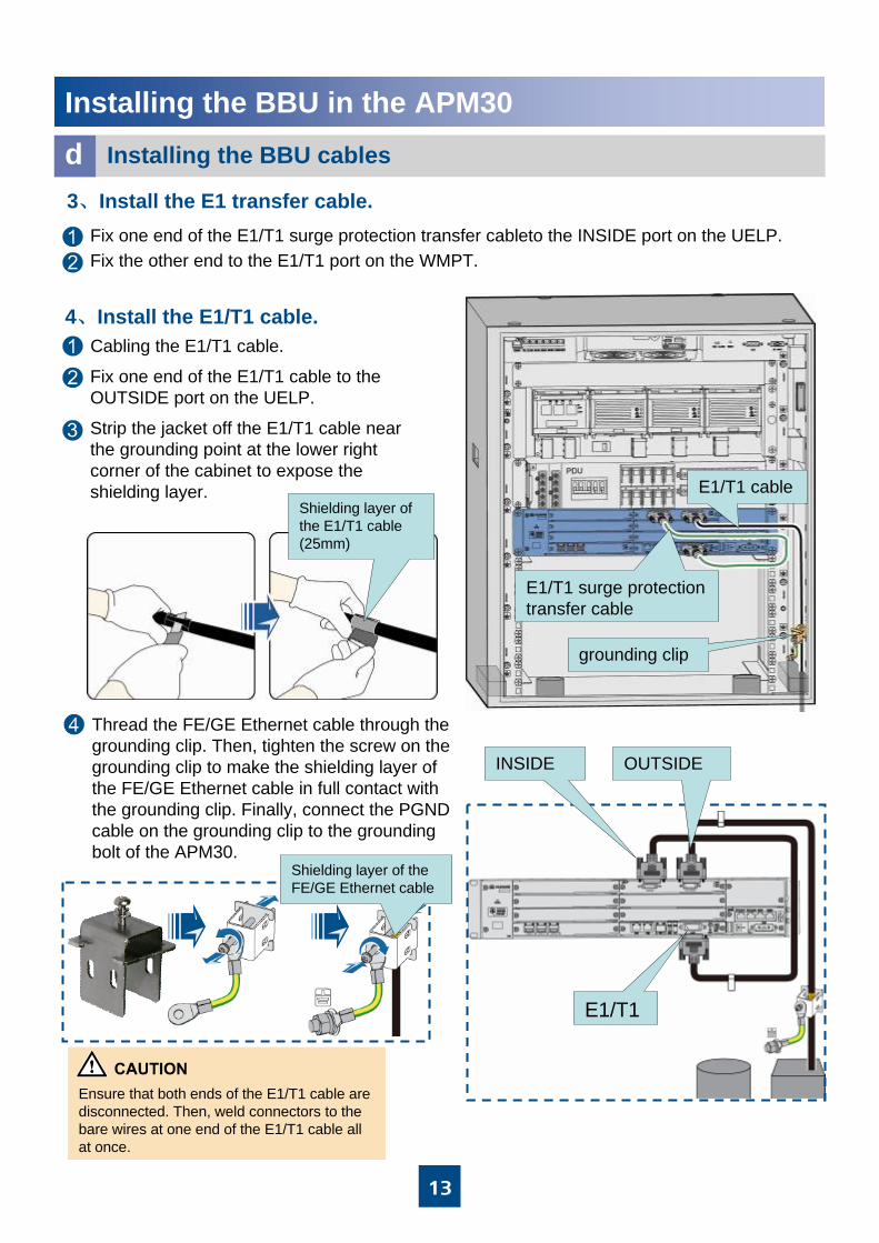
Strip the jacket off the E1/T1 cable near the grounding point at the lower right corner of the cabinet to expose the shielding layer.
Thread the FE/GE Ethernet cable through the grounding clip. Then, tighten the screw on the grounding clip to make the shielding layer of the FE/GE Ethernet cable in full contact with the grounding clip. Finally, connect the PGND cable on the grounding clip to the grounding bolt of the APM30.
Fix one end of the E1/T1 cable to the OUTSIDE port on the UELP.
Fix one end of the E1/T1 surge protection transfer cableto the INSIDE port on the UELP.
Installing the BBU in the APM30
d Installing the BBU cables
3、Install the E1 transfer cable.
Fix the other end to the E1/T1 port on the WMPT.
4、Install the E1/T1 cable.
E1/T1 surge protection transfer cable
Cabling the E1/T1 cable.
E1/T1 cable
Shielding layer of the FE/GE Ethernet cable
Shielding layer of the E1/T1 cable(25mm)
INSIDE
E1/T1
OUTSIDE
grounding clip
Ensure that both ends of the E1/T1 cable are disconnected. Then, weld connectors to the bare wires at one end of the E1/T1 cable all at once.
14
Installing the BBU in the APM30
d Installing the BBU Cables
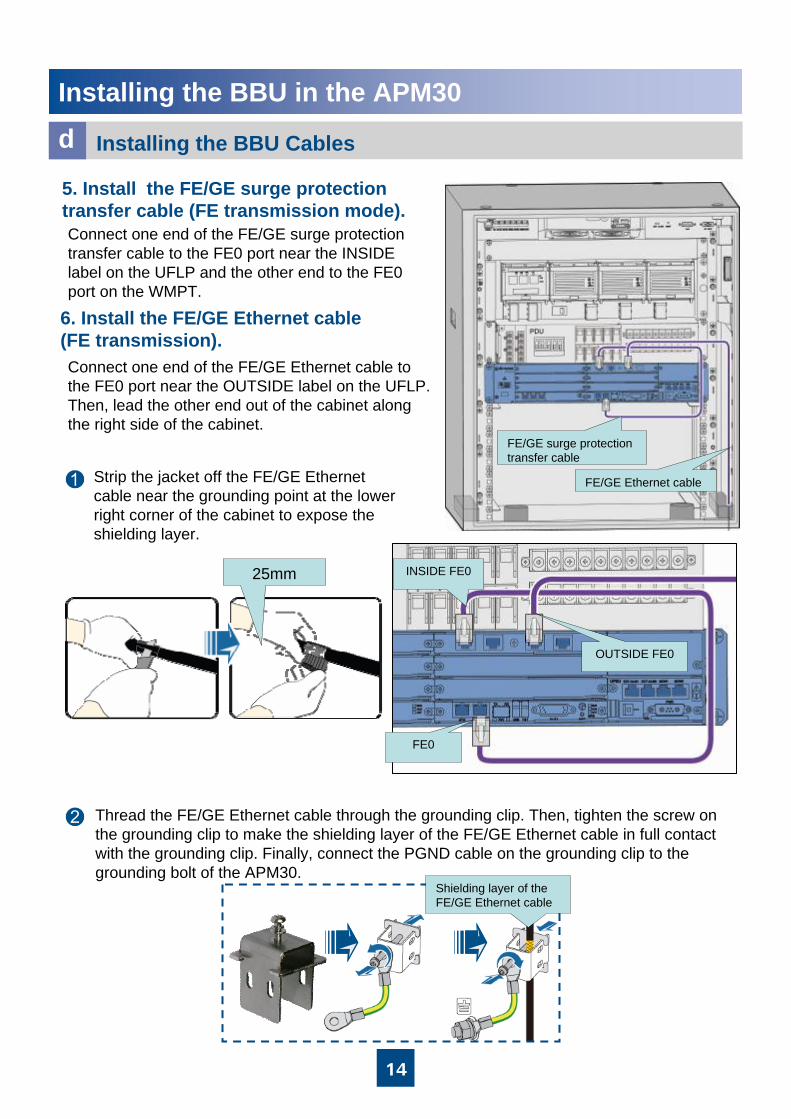
FE/GE surge protection transfer cable
FE/GE Ethernet cable
25mm
Thread the FE/GE Ethernet cable through the grounding clip. Then, tighten the screw on the grounding clip to make the shielding layer of the FE/GE Ethernet cable in full contact with the grounding clip. Finally, connect the PGND cable on the grounding clip to the grounding bolt of the APM30.
Shielding layer of the FE/GE Ethernet cable
Connect one end of the FE/GE surge protection transfer cable to the FE0 port near the INSIDE label on the UFLP and the other end to the FE0 port on the WMPT.
5. Install the FE/GE surge protection transfer cable (FE transmission mode).
6. Install the FE/GE Ethernet cable (FE transmission).Connect one end of the FE/GE Ethernet cable to the FE0 port near the OUTSIDE label on the UFLP. Then, lead the other end out of the cabinet along the right side of the cabinet.
Strip the jacket off the FE/GE Ethernet cable near the grounding point at the lower right corner of the cabinet to expose the shielding layer.
INSIDE FE0
FE0
OUTSIDE FE0

15
Installing the BBU in the APM30
d Installing the BBU Cables
External alarm cable
Monitoring signal cable between the APMI and the BBU
EXT-ALM1
Fix the RJ45 connector at one end of the cable to the MON1 port on the UPEU.7. Install the monitoring signal cable between the APMI and the BBU.
Connect one end of the alarm cable to the EXT-ALM port on the UPEU, and the other end to the associated alarm device.
8. Install the external alarm cable.
The port on the external alarm device is added depending on field requirements.
MON1
TX+
TX- RX+
RX-

16
Installing the BBU in the APM30
d Installing the BBU Cables
Cut off the RJ45 connector of the EMUA monitoring signal cable, and then connect the four exposed bare wires to the RX+, RX-, TX+, and TX- ports on the APMI. For the relationship between the ports and wires. Fix the DB9 connector to the corresponding port on the EMUA.
RX-WhiteX2.6X1.5
RX+Twisted pairBlueX2.2X1.4
TX-OrangeX2.7X1.2
TX+Twisted pairWhiteX2.3X1.1
Port on the APMITypeColorPin on the DB9 Male Connector
Pin on the RJ45 Connector
EMUA monitoring signal cable
9. Install the EMUA monitoring signal cable.

17
Installing the BBU in the APM30H(Ver.A)
CPRI port on the RRUCPRI port on the WBBPCPRI optical cable
Associated alarm deviceEXT-ALM0 or EXT-ALM1 on UPEUExternal alarm cable
The other end is connected to...
One end is connected to...
MON1 port on the BBUCOM IN port on the HEUAMonitoring signal cable
External transmission deviceOUTSIDE port on the UELPE1/T1 cable
INSIDE port on the UELPE1/T1 port on the WMPTE1 transfer cable
PWR port on the BBULOAD3 terminal of the PDUBBU power cable
Installation PositionCable
a BBU Cable Connections
abc
def
The procedure for installing the BBU case in the APM30H is the same as that in the APM30. For details, see pages 8–15. The following figure shows the cable connections of the BBU. Page 17 shows how to install the monitoring signal cable between the HEUA and the BBU in the APM30H.
ab
c de
f
b
ce
d
a

18
Installing the BBU in the APM30H(Ver.A)
MON1
COM IN
UPEU on the BBU
HEUA
b Installing the Monitoring Signal Cable between the HEUA andthe BBU

19
Installing the BBU in the APM30(+24 V)
EXT-ALM1 on the UPEUMonitoring port on the cabinetMonitoring signal cable for the cabinet
The other end is connected to...
One end is connected to...
CPRI port on the RRUCPRI port on the WBBPCPRI optical cable
Associated alarm deviceEXT-ALM0 or EXT-ALM1 on UPEUExternal alarm cable
External transmission deviceOUTSIDE port on the UELPE1/T1 cable
INSIDE port on the UELPE1/T1 port on the WMPTE1 surge protection transfer cable
PWR port on the BBULOAD6 terminal of the DCDUBBU power cable
Installation PositionCable
a BBU Cable Connections
ab
c
d
ef
The procedure for installing the BBU in the APM30 (+24 V) is the same as that in the APM30. For details, see pages 8–15. The following figure shows the cable connections of the BBU. Page 19 shows how to install the monitoring signal cable of the cabinet.
ab
c
d
f e
cb
a

20
Installing the BBU in the APM30(+24 V)
b Installing the Monitoring Signal Cable of the Cabinet
Pin assignment of the monitoring signal cable of the cabinet
Twisted pair
Twisted pair
Twisted pair
Twisted pair
Wire Type
DC/DC Power System
Door status sensor
DCDU-03B
APMI
Monitoring equipment
BrownX2.8X1.8
White/brownX2.7X1.7
BlueX2.4X1.4
White/blueX2.5X1.5
GreenX2.6X1.6
White/greenX2.3X1.3
OrangeX2.2X1.2
White/orangeX2.1X1.1
Wire ColorPin on the RJ45 Connector
Pin on the RJ45 Connector

21
Installing the BBU in the TMC
a BBU Cable Connections
To...From...
CPRI port on the RRUCPRI port on the WBBPCPRI optical cable
ALM1 port on the BBUWiring terminal of cabinet monitoringMonitoring signal cable
External transmission deviceOUTSIDE port on the UELPE1/T1 cable
INSIDE port on the UELPE1/T1 port on the WMPTE1 transfer cable
PWR port on the BBULOAD6 terminal of the PDUBBU power cable
Installation PositionCable
abc
de
The procedure for installing the BBU in the TMC is the same as that in the APM30. For details, see pages 8–15.
a
b
c
d
e
b c
a

22
a
b
c
d
Installing the BBU in the TMC
Installing the BBU Cablesb
The white and green bare wire terminals are not distinguished from different wiring terminals.
Installing the TMC alarm cable:
a. Fix the RJ45 connector at one end of the alarm cable to the EXT_ALM1 port on the BBU.
b. Connect the two bare terminals X1.4 (blue) and X1.5 (white) to the alarm wiring terminals on the door status sensor.
c. Connect the two bare terminals X1.1 (white) and X1.2 (orange) to the OUT+ and OUT- alarm wiring terminals on the APMI.
d. Connect the two bare terminals X1.3 (white) and X1.6 (green) to the alarm wiring terminals on the DCDU.
APMI
Door status sensor
Wiring terminals for the surge protection and alarm cables
23
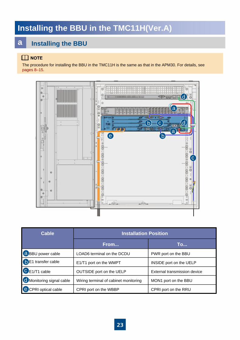
Installing the BBU in the TMC11H(Ver.A)
a Installing the BBU
To...From...
CPRI port on the RRUCPRI port on the WBBPCPRI optical cable
MON1 port on the BBUWiring terminal of cabinet monitoringMonitoring signal cable
External transmission deviceOUTSIDE port on the UELPE1/T1 cable
INSIDE port on the UELPE1/T1 port on the WMPTE1 transfer cable
PWR port on the BBULOAD6 terminal on the DCDUBBU power cable
Installation PositionCable
abc
de
The procedure for installing the BBU in the TMC11H is the same as that in the APM30. For details, see pages 8–15.
ab
c
d
e
cb
a
d

24
Installing the BBU in the APM30H(Ver.B)a
b BBU Cable Connections
M6 screws.
BBU
EPS
Slide the BBU close to the EPS to the 2 U space along the guide rails, and then tighten the four M6 screws on the BBU panel.
1. Installing the BBU Case
SLPU
Slide the SLPU box into the 1U space above the EPS in the cabinet, and then fasten the four M6 screws on the panel.
2. Installing the SLPU Case
a
b
c
d
e
fg
h
ab
b
c
de
f
gh
h
Alarm Equipment
Monitoring Equipment
Transmission equipment
Power System
E1 surge protection transfer cable
E1/T1 cable
Monitoring Cable
BBU Power Cable
FE surge protection transfer cable
FE/GE Ethernet cable
Alarm Cable
CPRI Optical cable
Installing the BBU Case
2N•m
M6X16
2N•m
M6X16

25
LOAD1
Installing the BBU in the APM30H(Ver.B)Installing the BBU cablesc
2. Install the CPRI optical cable .Fix one end of the CPRI optical cable to the CPRI port on the WBBP, fix the other end to the port labeled CPRI_W on the RRU. For details on the CPRI optical cable connections, see CPRI Cable Configuration Principles on pages 8-9.
2.1. Turn the puller on the optical module outwards, insert the optical module to the port CPRI 0 to CPRI2.2.2. Remove the dustproof caps from the optical connectors.
Insert the optical connector at one end of the CPRI optical cable into the optical module. lead the CPRI optical cable out of the cabinet along the left side of the cabinet.2.3. Wrap the winding pipe at the fiber tails.
Connect the OT terminal at one end to the LOAD1 terminal of the EPS01, and then link the 3V3 connector at the other end to the -48V port on the BBU.
1. Install BBU power cable.
Optical module
Puller
Connect the fiber tails labeled 1A and 1B to the CPRI_W port on the RRU.
Connect the fiber tails labeled 2A and 2B to one of the CPRI0 to CPRI2 ports on the WMPT
Winding pipe
TX RX

26
Installing the BBU in the APM30H(Ver.B)Installing the BBU cablesc
3.1. Fix one end of the E1/T1 surge protection transfer cableto the INSIDE port on the UELP .
3.2. Fix the other end to the E1/T1 port on the WMPT.
3. Install the E1 transfer cable.
4. Install the E1/T1 cable.4.1. Cabling the E1/T1 cable.
4.2. Fix one end of the E1/T1 cable to the OUTSIDE port on the UELP.
E1/T1 surge protection transfer cable
E1/T1 cable
Connect one end of the FE/GE surge protection transfer cable to the FE0 port near the INSIDE label on the UFLP and the other end to the FE0 port on the WMPT.
5. Install the FE/GE surge protection transfer cable (FE transmission mode).
6. Install the FE/GE Ethernet cable (FE transmission).Connect one end of the FE/GE Ethernet cable to the FE0 port near the OUTSIDE label on the UFLP. Then, lead the other end out of the cabinet along the right side of the cabinet.
FE transfer cable
FE/GE Ethernet cable
Ensure that both ends of the E1/T1 cable are disconnected. Then, weld connectors to the bare wires at one end of the E1/T1 cable all at once.

27
Installing the BBU in the APM30H(Ver.B)Installing the BBU Cablesc
7. Install the monitoring signal cable between the CMUA and the BBU.
COM_IN
MON1

28
Installing the BBU in the TMC11H(Ver.B)
Installing the BBUa1. Slide the BBU to the TMC11H along guide rails, and then tighten the four M6 screws on the BBU panel.
2. Slide the SLPU to the TMC11H along guide rails, and then tighten the four M6 screws on the SLPU panel.
BBU
DCDU
SLPU
2N•m
M6X16
Installing BBU Cablesb
LOAD6
Installation the BBU power cable.
2N•m
M6X16

29
Installing the BBU in the TMC11H(Ver.B)
Installing BBU Cablesb
E1/T1 port on the WMPTDB26 connectorE1 Surge Protection Transfer Cable
INSIDE port on the UELP DB25 connector
FE0 port at the OUTSIDE side on the UFLPRJ45 connectorFE/GE Ethernet cable
Port on the transmission device RJ45 connector
COM_IN port on the CMUA RJ45 connector
MON1 port on the BBURJ45 connectorMonitoring signal cable between the CMUA and the BBU
LOAD6 port on the DCDU-03BOT terminal
-48V port on the UPEU3V3 connectorBBU power cable
FE0 port at the INSIDE side on the UFLPRJ45 connectorFE Surge Protection Transfer Cable
FE0 port on the WMPTRJ45 connector
Port on the transmission device The connector needs to be made on site according to the field requirements.
OUTSIDE port on the UELPDB26 connectorE1/T1 cable
The connectors labeled 1A and 1B are connected to the optical module on the port labeled CPRI_W on the RRU.
DLC
The connectors labeled 2A and 2B are connected to the optical module on the port labeled CPRI0 to CPRI2 on the WBBP.
DLCCPRI optical cable
Connects toConnector TypeCable
The procedure for installing BBU cables (except the power cable) in the TMC11H cabinet is the same as that in the APM30H(Ver.B). For details, see the description on pages 23 to 26.
For details on the BBU cable connections, see BBU Cable Connections on pages 23.
30
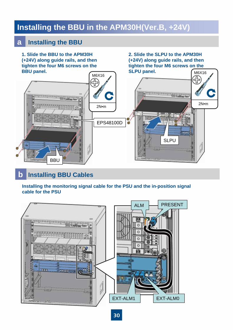
Installing the BBU in the APM30H(Ver.B, +24V)
Installing the BBUa1. Slide the BBU to the APM30H (+24V) along guide rails, and then tighten the four M6 screws on the BBU panel.
BBU
2N•m
M6X16
2. Slide the SLPU to the APM30H (+24V) along guide rails, and then tighten the four M6 screws on the SLPU panel.
SLPU
EPS48100D
Installing BBU Cablesb
ALM PRESENT
EXT-ALM1 EXT-ALM0
Installing the monitoring signal cable for the PSU and the in-position signal cable for the PSU
2N•m
M6X16
31
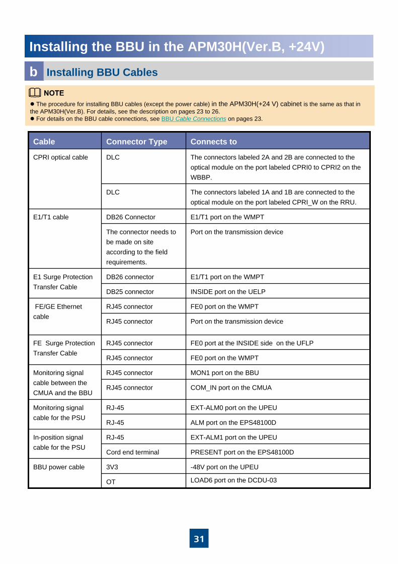
Installing BBU Cablesb
Installing the BBU in the APM30H(Ver.B, +24V)
FE0 port at the INSIDE side on the UFLPRJ45 connectorFE Surge Protection Transfer Cable
FE0 port on the WMPTRJ45 connector
E1/T1 port on the WMPTDB26 connectorE1 Surge Protection Transfer Cable
INSIDE port on the UELP DB25 connector
-48V port on the UPEU3V3BBU power cable
LOAD6 port on the DCDU-03OT
EXT-ALM1 port on the UPEURJ-45In-position signal cable for the PSU
PRESENT port on the EPS48100DCord end terminal
EXT-ALM0 port on the UPEURJ-45Monitoring signal cable for the PSU
ALM port on the EPS48100DRJ-45
MON1 port on the BBURJ45 connectorMonitoring signal cable between the CMUA and the BBU
COM_IN port on the CMUA RJ45 connector
FE0 port on the WMPTRJ45 connectorFE/GE Ethernet cable
Port on the transmission device RJ45 connector
Port on the transmission device The connector needs to be made on site according to the field requirements.
E1/T1 port on the WMPTDB26 ConnectorE1/T1 cable
The connectors labeled 1A and 1B are connected to the optical module on the port labeled CPRI_W on the RRU.
DLC
The connectors labeled 2A and 2B are connected to the optical module on the port labeled CPRI0 to CPRI2 on the WBBP.
DLCCPRI optical cable
Connects toConnector TypeCable
The procedure for installing BBU cables (except the power cable) in the APM30H(+24 V) cabinet is the same as that in the APM30H(Ver.B). For details, see the description on pages 23 to 26.
For details on the BBU cable connections, see BBU Cable Connections on pages 23.

32
Installing the BBU in the 19-Inch Cabinet
BBU Cable Connectionsa
abc
d
e
f g
hi
k
a
j
a
b
c
d
e
f
g
h
i
j
kATN port on the rear panel of the WGRUN-shaped female connector
GPS antennaSMA male connectorClock signal cable
Outdoor ground barOT terminal (6mm²-M8)
Ground terminal of the BBUOT terminal (6mm²-M4)PGND cable of the BBU
NEG(-) and RTN(+) ports on the DCDUOT terminal
External power supply equipmentOT terminalDCDU power cable
POWER port on the rear panel of the WGRUTwo-hole male connector
LOAD7 to LOAD8 ports on the DCDUOT terminalWGRU power cable
RGPS port on the USCURJ45 connector
COM1 port on the WGRUPrepared according to actual requirements at sitesGPS signal cable
RGPS port on the USCUPrepared according to actual requirements at sites
PPS port on the WGRURJ45 connectorPPS signal cable
CPRI port on the BBUDLC connector
CPRI port on the RRUDLC connector CPRI optical fiber
MON or ALM port on the BBURJ45 connector
External transmission equipmentRJ45 connectorMonitoring signal cable
FE0 port on the WMPTRJ45 connector
External transmission equipmentRJ45 connector FE/GE Ethernet cable
E1/T1 port on the WMPTDB26 connector
External transmission equipmentPrepared according to actual requirements at sitesE1/T1 cable
PWR port on the BBU 3V3 connector
LOAD6 port on the DCDUOT terminalBBU power cable
Connected toConnector TypeCable

33
Installing the BBU in the 19-Inch Cabinet
Installing the BBU Case cSlide the BBU case into the cabinet. Then, tighten the four M6 screws.
Space Requirementsb
25 mm on the left of the BBU for ventilation25 mm on the right of the BBU for ventilation70 mm in front of the BBU for cablingA minimum of 800 mm in front of the panel for maintenance

34
Installing the DCDU-03BeSlide the DCDU-03B case into the cabinet, and tighten the four M6 screws.
Installing the WGRU (optional)d
WGRU
Slide the WGRU case into the cabinet, and tighten the four M6 screws.
Back
Installing the BBU in the 19-Inch Cabinet
Front
25 mm on the left of the WGRU for ventilation25 mm on the right of the WGRU for ventilation70 mm in front of the WGRU for cablingA minimum of 800 mm in front of the panel for maintenance

35
PWR
Installing the BBU in the 19-Inch Cabinet
Installing BBU Cablesf
EXT-ALM0/1 MON0/1
Grounding bolt on the right side
of the BBU
Grounding bar
LOAD6
3. Install the signal cable.
1. Install the PGND cable.
2. Install the power cable.
36
Installing the BBU in the 19-Inch CabinetInstalling BBU Cablesf
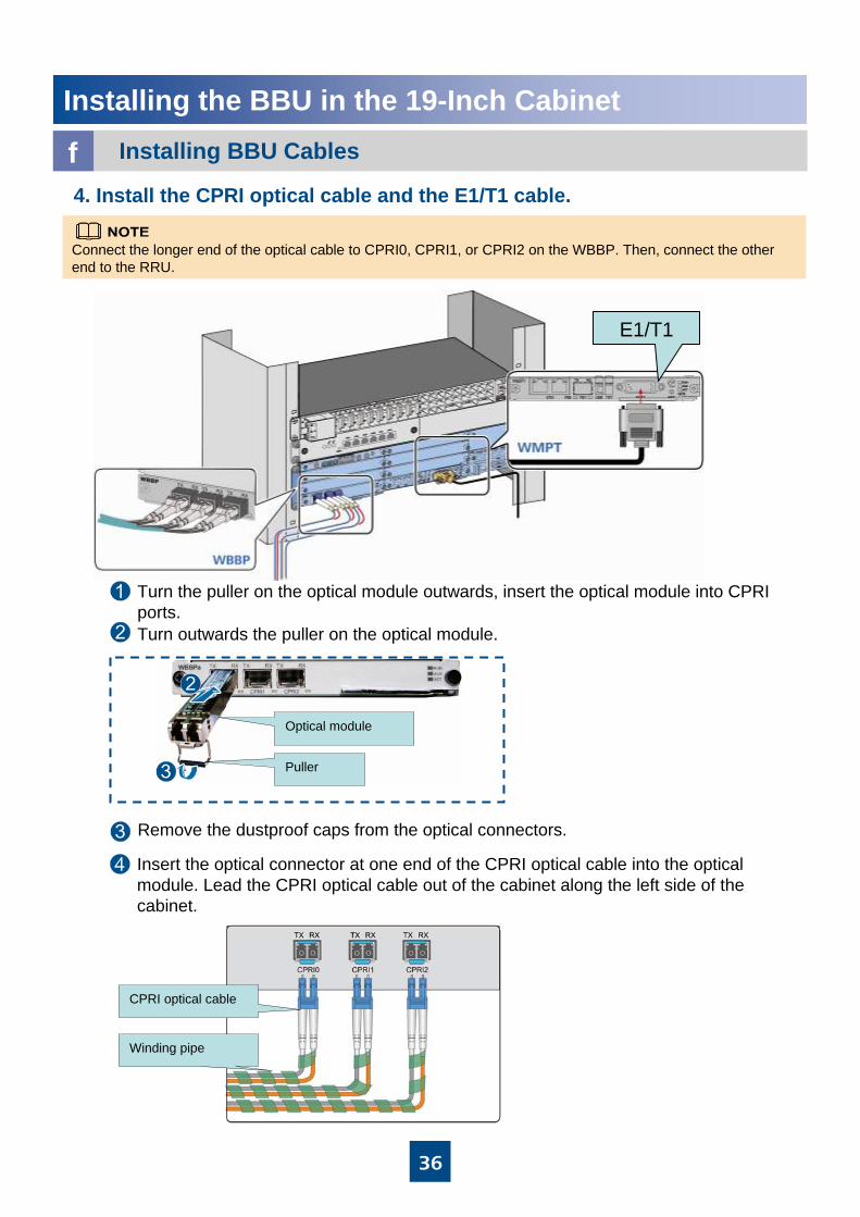
4. Install the CPRI optical cable and the E1/T1 cable.
E1/T1
Connect the longer end of the optical cable to CPRI0, CPRI1, or CPRI2 on the WBBP. Then, connect the other end to the RRU.
Optical module
Puller
Turn outwards the puller on the optical module.
Turn the puller on the optical module outwards, insert the optical module into CPRI ports.
Remove the dustproof caps from the optical connectors.
Insert the optical connector at one end of the CPRI optical cable into the optical module. Lead the CPRI optical cable out of the cabinet along the left side of the cabinet.
CPRI optical cable
Winding pipe

37
ANT
Installing the BBU in the 19-Inch Cabinet
Installing the WGRU Cablesg1. Install the PGND cable.
Grounding bolt on the right side of the WGRU
Grounding bar
POWERLOAD8
Back
Back
Back
The PGND cable is connected to the closest grounding bar.
2. Install the GPS clock signal cable.
The GPS clock signal cable is routed upwards along the column of the cabinet.
3. Install the power cable.
The power cable is routed from the output terminal on the DCDU to the back, avoiding the front panels of the DCDU and WGRU.

38
Installing the BBU in the 19-Inch CabinetInstalling the WGRU Cablesg
4. Install the signal cable.
The GPS signal is transmitted over the COM1 port and the PPS signal is transmitted over the PPS1 port.
Wire Color
Silkscreen
PortPinPort
RX-
RX+
TX-
TX+
1S-
1S+
GreenUSCU-RGPSPin 6-COM1_COM_TXD-
WGRU-COM1
Green and white
USCU-RGPSPin 3-COM1_COM_TXD+
WGRU-COM1
OrangeUSCU-RGPSPin 2-COM1_COMRXD-
WGRU-COM1
Orange and white
USCU-RGPSPin 1-COM1_COMRXD+
WGRU-COM1
OrangeUSCU-RGPSPin 2-CLK1_PPS_TXD-WGRU-PPS1
Orange and white
USCU-RGPSPin 1-CLK1_PPS_TXD+
WGRU-PPS1
39
Installing the BBU on the Wall
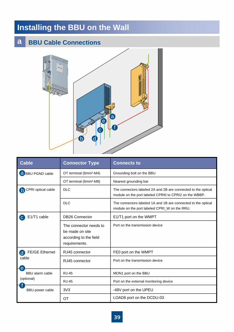
BBU Cable Connectionsa
Nearest grounding barOT terminal (6mm²-M8)
Grounding bolt on the BBUOT terminal (6mm²-M4)BBU PGND cable
Port on the external monitoring deviceRJ-45
MON1 port on the BBURJ-45 BBU alarm cable (optional)
LOAD6 port on the DCDU-03OT
-48V port on the UPEU3V3BBU power cable
FE0 port on the WMPTRJ45 connectorFE/GE Ethernet cable Port on the transmission device RJ45 connector
Port on the transmission device The connector needs to be made on site according to the field requirements.
E1/T1 port on the WMPTDB26 ConnectorE1/T1 cable
The connectors labeled 1A and 1B are connected to the optical module on the port labeled CPRI_W on the RRU.
DLC
The connectors labeled 2A and 2B are connected to the optical module on the port labeled CPRI0 to CPRI2 on the WBBP.
DLCCPRI optical cable
Connects toConnector TypeCable
a
b
c
d
e
f
a
bc
ef
d

40
Installing the BBU on the Wall
A single BBU BBU+DCDU-03B
ab Installing the BBU Case
Space Requirementsa
Install the mounting ears for wall installation.
BBU
DCDU-03B
≥100mm ≥50mm
≥50mm
≥600mm
≥20mm
≥800mm
Mounting ear on the BBU case
Mounting ear for wall installation
2N•m
M6X12
The DCDU is installed near the BBU.

41
a Install the expansion bolts.d ae Installing the BBU Case
Place the mounting ears for wall installation against the wall, and then use the marking pen to mark the holes of the mounting ears for wall installation.
Installing the BBU on the Wall
Installing the BBUc
Bolt M6×60Spring washer 6Flat washer 6Expansion tube
Flat washer
Spring washer
45N•m
M6X60
BBU
wall

42
Installing the BBU on the Wall
Installing the DCDU-03B Casef
55mm~60mm
20mm
Wall
2N•m
M6X12
45N•m
M6X60
1. Installing the mounting ears of the DCDU-03B.
2. Place the mounting ears for wall installation against the wall, and then use the marker to mark the holes of the mounting ears for wall installation.
3. Install the expansion bolt. 4. Install the DCDU-03 on the wall.
Bolt M6 x 60
Spring washer 6Flat washer 6Expansion tube
Nut
Ф8

43
Installing the BBU in the OMB Cabinet
Installing the brackets on the metal pole and mounting platea
Use a level bar to adjust the levelness of the brackets to ensure that the front and back brackets are on the same plane.
1. Install the brackets on the metal pole.
255-306 kgf·cm
M10x110Flat washer
Spring washer
Bolt
2. Install the mounting plate.
255~306kgf·cm
M10X40
Flatwasher
SpringwasherBolt
appearance of the mounting plate

44
Installing the BBU in the OMB Cabinet
Installing the OMB CabinetbSlide the BBU case into the OMB cabinet gently. Then, tighten the four M6 screws.
c Installing the BBU Cables
Grounding bar
Ensure the FAN is in the bottom when installing the BBU.
1. Install the PGND cable of OMB cabinet.

45
Installing the BBU in the OMB Cabinet
Installing the BBU Cablesc
LOAD6
NEG(-)
RNT (+)
2. Install the input power cable.
3. Install the BBU power cable.

46
Installing the BBU in the OMB Cabinet
Installing the BBU Cablesc4. Install the E1/T1 cable (E1 transmission).
Shielding layer
Shielding layer(25 mm)
PGND
INSIDE
OUTSIDE
E1/T1
a
b
c
d
a
b
c
dE1/T1 surge protection transfer cableE1/T1
cable
E1/T1 surge protection transfer cable

47
a
b
ca
b
c
Installing the BBU in the OMB Cabinet
Installing the BBU Cablesc5. Install the FE/GE Ethernet cable (FE transmission).
6. Install the CPRI optical cable.
Connect the longer end of the optical cable to CPRI0, CPRI1, or CPRI2 on the WBBP. Then, connect the other end to the RRU.
Optical module
Puller
3. Remove the dustproof caps from the optical connectors.
2. Turn outwards the puller on the optical module.
4. Insert the optical connector at one end of the CPRI optical cable into the optical module. lead the CPRI optical cable out of the cabinet along the left side of the cabinet.
1. Insert the optical module into the CPRI0, CPRI1, or CPRI2 port.
INSIDE FE0
FE/GE surge protection transfer cable
FE/GE Ethernet cableOUTSIDE FE0
FE0
FE/GE surge protection transfer cable
48
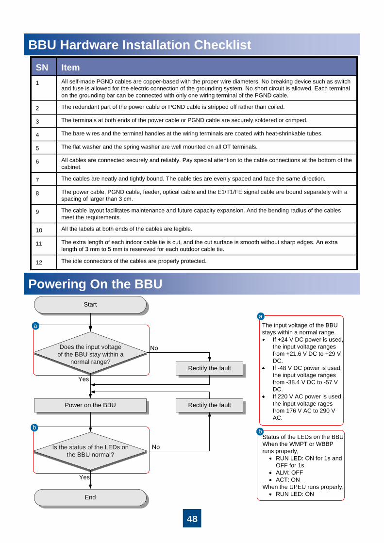
参考信息BBU Hardware Installation Checklist
Powering On the BBU
Does the input voltageof the BBU stay within a
normal range?
Power on the BBU
Start
End
a
Yes
Rectify the fault
b
Is the status of the LEDs on the BBU normal?
No
Yes
No
Rectify the fault
aThe input voltage of the BBU stays within a normal range.
If +24 V DC power is used, the input voltage ranges from +21.6 V DC to +29 V DC.If -48 V DC power is used, the input voltage ranges from -38.4 V DC to -57 V DC.If 220 V AC power is used, the input voltage rages from 176 V AC to 290 V AC.
Status of the LEDs on the BBU:When the WMPT or WBBP runs properly,
RUN LED: ON for 1s and OFF for 1sALM: OFFACT: ON
When the UPEU runs properly,RUN LED: ON
b
All the labels at both ends of the cables are legible.10
The extra length of each indoor cable tie is cut, and the cut surface is smooth without sharp edges. An extra length of 3 mm to 5 mm is resereved for each outdoor cable tie.
11
The cable layout facilitates maintenance and future capacity expansion. And the bending radius of the cables meet the requirements.
9
The idle connectors of the cables are properly protected.12
The power cable, PGND cable, feeder, optical cable and the E1/T1/FE signal cable are bound separately with a spacing of larger than 3 cm.
8
The cables are neatly and tightly bound. The cable ties are evenly spaced and face the same direction.7
All cables are connected securely and reliably. Pay special attention to the cable connections at the bottom of the cabinet.
6
The flat washer and the spring washer are well mounted on all OT terminals.5
The bare wires and the terminal handles at the wiring terminals are coated with heat-shrinkable tubes.4
The terminals at both ends of the power cable or PGND cable are securely soldered or crimped.3
The redundant part of the power cable or PGND cable is stripped off rather than coiled.2
All self-made PGND cables are copper-based with the proper wire diameters. No breaking device such as switch and fuse is allowed for the electric connection of the grounding system. No short circuit is allowed. Each terminal on the grounding bar can be connected with only one wiring terminal of the PGND cable.
1
ItemSN

49
Checking the DIP Switches of the BBUa
ESD glovesESD strap
Removing the BBU Boardsb
Wear an ESD wrist strap or a pair of ESD gloves when performing operations related to the boards, as shown in the figure below.
Appendix
Obtaining the ESNRecord the Electronic Serial Number (ESN) shown on the label attached to the mounting ear of the BBU, and report the ESN to the engineer for the commissioning of the base station.
ESN

50
Appendix
Setting the DIP Switches of the PMUc
Set as ON, indicating that the baud rate is 9600. (If it is set as OFF, the baud rate is 19200.)
Selecting baud rate for communicating with the BTS
6
Set as OFFReserved and not defined7 and 8
(1) Switches 1 to 5 correspond to bits 0 to 4. ON:1; OFF: 0
For example: to set the address of PMU to 3, set switches 3 to 5 as OFF.
(2) Default setting before delivery:
1 (BIT0), ON
2 (BIT1), ON
3 (BIT2), OFF
4 (BIT3), OFF
5 (BIT4), OFF
Defining the communication address of the PMU
1~5
No. OperationFunction
Set the DIP switches of the PMU:

51
Checking the DIP Switches of the UELPd
Settings of the DIP switches on the UELP
75-ohm E1 Mode
Other Modes
T1 Mode
75-ohm E1 Mode 120-ohm E1 Mode
Settings of the DIP switches on the WMPT
Checking the DIP Switches of the WMPTe
Reinstalling the Boardsf
The black part indicates the position of a DIP switch.
Appendix

52
Pin Assignment of the BBU Signal Cablesg75-ohm E1/T1 cable
TX4-RingX1.26
TX4+8TipX1.25
TX3-RingX1.24
TX3+6TipX1.23
TX2-RingX1.22
TX2+4TipX1.21
TX1-RingX1.20
TX1+2TipX1.19
RX4-RingX1.8
RX4+7TipX1.7
RX3-RingX1.6
RX3+5TipX1.5
RX2-RingX1.4
RX2+3TipX1.3
RX1-RingX1.2
RX1+1TipX1.1
LabelCoaxial SN.Wire TypePin on the DB26 Male Connector
Appendix

53
Pin Assignment of the BBU Signal Cablesg120-ohm E1/T1 cable
TX4-RedX1.26
TX4+Twisted pair
GreenX1.25
TX3-RedX1.24
TX3+Twisted pair
OrangeX1.23
TX2-RedX1.22
TX2+Twisted pair
BlueX1.21
TX1-WhiteX1.20
TX1+Twisted pair
GreyX1.19
RX4-WhiteX1.8
RX4+Twisted pair
BrownX1.7
RX3-WhiteX1.6
RX3+Twisted pair
GreenX1.5
RX2-WhiteX1.4
RX2+Twisted pair
OrangeX1.3
RX1-WhiteX1.2
RX1+Twisted pair
BlueX1.1
LabelWire TypeWire ColorPin on the DB26 Male Connector
Appendix

54
Pin Assignment of the BBU Signal CablesgFE/GE Ethernet cable
X2.7White/brownX1.7
X2.8Twisted pairBrownX1.8
X2.5White/blueX1.5
X2.4Twisted pairBlueX1.4
X2.3White/greenX1.3
X2.6Twisted pairGreenX1.6
X2.1White/orangeX1.1
X2.2Twisted pairOrange X1.2
Pin on the RJ45 Connector
Wire TypeWire ColorPin on the RJ45 Connector
RX-Twisted pairX5WhiteX1.5
RX+Twisted pairX4BlueX1.4
TX-Twisted pairX3OrangeX1.2
TX+Twisted pairX2WhiteX1.1
Port on the APMIWire TypePins on the X2, X3, X4, and X5
Wire Color
Pin on the RJ45 Connector
Monitoring signal cable between the APMI and the BBU
Appendix

55
Pin Assignment of the BBU Signal Cablesg
EMUA monitoring signal cable
BrownX2.8X1.8
Twisted pairWhite/brownX2.7X1.7
BlueX2.4X1.4
Twisted pairWhite/blueX2.5X1.5
GreenX2.6X1.6
Twisted pairWhite/greenX2.3X1.3
OrangeX2.2X1.2
Twisted pairWhite/orangeX2.1X1.1
Wire TypeWire ColorPin on the RJ45 Connector
Pin on the RJ45 Connector
Alarm cable
RX-Twisted pair
WhiteX2.6X1.5
RX+Twisted pair
BlueX2.2X1.4
TX-Twisted pair
OrangeX2.7X1.2
TX+Twisted pair
WhiteX2.3X1.1
Port on the APMIWire TypeWire Color
Pin on the DB9 Male Connector
Pin on the RJ45 Connector
Appendix

56
Change History
10 (2010-03-05)
This is the tenth commercial release.
Compared with issue 09 (2009-11-25), Obtaining the ESN is added.
09 (2009-11-25)
This is the ninth commercial release.
Compared with issue 08 (2009-09-30), the figure of installing the WGRU signal cable is modified.
08 (2009-09-30)This is the eighth commercial release.
Compared with issue 07 (2009-08-30), the configuration principles of the BBU boards are modified.
Compared with issue 07 (2009-08-30), the installation scenarios of APM30H(Ver.B), TMC11H(Ver.B) and APM30H(Ver.B, +24V) are added.
07 (2009-08-30)This is the seventh commercial release.
Compared with issue 06 (2009-06-30), the installation of WGRU is added.
06 (2009-06-30)
This is the sixth commercial release.
Compared with issue 05 (2009-01-23), the configuration principles of the BBU boards is modified.

HUAWEI TECHNOLOGIES CO., LTD.Huawei Industrial Base Bantian Longgang
Shenzhen 518129People’s Republic of China
www.huawei.com