bc procat se kohler cv680 w/52 side discharge 942521j
TRANSCRIPT

PAR
TS M
AN
UA
L
MA
N 4
1682
55R
ev. B
09-
2013
942520JBC PROCAT SE KOHLER CV680 W/52 SIDE DISCHARGE
942521J
BC PROCAT SE KOHLER CV740 W/61 SIDE DISCHARGE
942522JBC PROCAT SE KAW FX651V W/52 SIDE DISCHARGE
942523J
BC PROCAT SE KAW FX730V W/61 SIDE DISCHARGE
OPERATOR’S MANUAL 4168256 www.bobcatturf.com

CALIFORNIAProposition 65 Warning
Diesel engine exhaust and some of its constituents are known to the State of California to cause cancer, birth defects and other reproductive harm.
Californie Proposition 65 Avertisse-ment
Les échappements des moteurs diesel et certains de leurs composés sont recon-nus par l’Etat de Californie pour être cancérigènes, provoquer des défauts con-génitaux et d’autres dangers en matière de reproduction.
ADVERTENCIA
AVERTISSEMENT
WARNINGThe engine exhaust from this product contains chemicals known to the State of California to cause cancer, birth defects or other reproductive harm.
California Advertencia de la Proposicion 65
El estado de California hace saber que los gases de escape de los mo-tores diesel y algunos de sus com-ponentes producen cáncer, defectos de nacimiento y otros daños en el proceso de reproducción humana.
L’émission du moteur de ce matériel contient des produits chimiques que l’Etat de Californie considère être cancérigènes, provoquer des défauts congénitaux et d’autres dangers en matière de reproduction.
El estado de California hace saber que los gases de escape de este producto contienen productos quÍmi-cos que producen cáncer, defectos de nacimiento y otros daños en el proceso de reproducción humana.
CALIFORNIAProposition 65 Warning
Battery posts, terminals, wiring insulation, and related accessories contain lead and lead compounds, chemicals known to the State of California to cause cancer and birth defects or other reproductive harm. WASH HANDS AFTER HANDLING.

1
PROCAT SEIMPORTANT MESSAGE
Thank you for purchasing this Schiller Grounds Care, Inc. product. You have purchased a world class mowing product, one of the best designed and built anywhere.
This machine comes with an Operation and Safety Manual and a separate Setup, Parts and Maintenance Manual. The useful life and good service you receive from this machine depends to a large extent on how well you read and understand these manuals. Treat your machine properly, lubricate and adjust it as instructed, and it will give you many years of reliable service.
Your safe use of this Schiller Grounds Care, Inc. product is one of our prime design objectives. Many safety features are built in, but we also rely on your good sense and care to achieve accident-free operation. For best protection, study the manuals thoroughly. Learn the proper operation of all controls. Observe all safety precautions. Follow all instructions and warnings completely. Do not remove or defeat any safety features. Make sure those who operate this machine are as well informed and careful in its use as you are.
See a Schiller Grounds Care, Inc. dealer for any service or parts needed. Schiller Grounds Care, Inc. service ensures that you continue to receive the best results possible from Schiller Grounds Care, Inc. products. You can trust Schiller Grounds Care, Inc. replacement parts because they are manufactured with the same high precision and quality as the original parts.
Schiller Grounds Care, Inc. designs and builds its equipment to serve many years in a safe and productive manner. For longest life, use this machine only as directed in the manuals, keep it in good repair and follow safety warnings and instructions. You’ll always be glad you did.
Schiller Grounds Care, Inc.One Bob Cat Lane
Johnson Creek, WI 53038-0469
08-2012
TABLE OF CONTENTS ..................................................................... FIGURES .......................................................... PAGESAFETY ................................................................................................................................................................................ 2ASSEMBLY AND SETUP .................................................................................................................................................. 3-5MAINTENANCE CHART ..................................................................................................................................................... 6MAINTENANCE RECORD ................................................................................................................................................... 7MAINTENANCE ............................................................................................................................................................. 8-14ADJUSTMENTS ............................................................................................................................................................ 15-19BELT REPLACEMENT ...................................................................................................................................................... 20SPECIFICATIONS ......................................................................................................................................................... 21-24PARTS SECTION ............................................................................................................................................................... 25UPPER ENGINE DECK ASSY AIR COOLED .................................FIGURE 1 .......................................................... 26, 27LOWER ENGINE DECK ASSY/CLUTCH........................................FIGURE 2 ............................................................ 28, 29BUMPER .........................................................................................FIGURE 3 ............................................................ 30, 31FUEL TANKS/CONTROL PANEL ....................................................FIGURE 4 ............................................................ 32, 33BRAKES/REAR WHEEL .................................................................FIGURE 5 ............................................................ 34, 35OIL COOLER ...................................................................................FIGURE 6 ............................................................ 36, 37 HYDRAULICS - AIR COOLED ........................................................FIGURE 7 ............................................................ 38, 39HYDROGEAR PUMP .....................................................................FIGURE 8 ............................................................ 40, 41KAWASAKI WIRE HARNESS- AIR COOLED .................................FIGURE 9 ............................................................ 42, 43SEAT ASSEMBLY & ROPS .............................................................FIGURE 10 .......................................................... 44, 45FOLDING ROPS KIT .......................................................................FIGURE 11 .......................................................... 46, 47STEERING/DECK LIFT ...................................................................FIGURE 12 .......................................................... 48, 49CRADLE ASSEMBLY ......................................................................FIGURE 13 .......................................................... 50, 51CRADLE & CASTER ASSEMBLY ...................................................FIGURE 14 .......................................................... 52, 5352" SIDE DISCHARGE ...................................................................FIGURE 15 .......................................................... 54, 5561” SIDE DISCHARGE....................................................................FIGURE 16 .......................................................... 56, 57BELTS-CUTTERDECK ....................................................................FIGURE 17 .......................................................... 58, 59DECALS-POWER UNIT ..................................................................FIGURE 18 .......................................................... 60, 61DECALS-CUTTERDECKS ..............................................................FIGURE 19 .......................................................... 62, 63

2
PROCAT SESAFETY
NOTICE !!!Unauthorized modifications may present extreme safety hazards to operators and bystanders and could also result in product damage.
Schiller Grounds Care, Inc. strongly warns against, rejects and disclaims any modifications, add-on accessories or product alterations that are not designed, developed, tested and approved by Schiller Grounds Care, Inc.Engineering Department. Any Schiller Grounds Care, Inc.product that is altered, modified or changed in any manner not specifically authorized after original manufacture-including the addition of “after-market” accessories or component parts not specifically approved by CGC, Inc.-will result in the Schiller Grounds Care, Inc.Warranty being voided.
Any and all liability for personal injury and/or property damage caused by any unauthorized modifications, add-on accessories or products not approved by Schiller Grounds Care, Inc.will be considered the responsibility of the individual(s) or company designing and/or making such changes. Schiller Grounds Care, Inc.will vigorously pursue full indemnification and costs from any party responsible for such unauthorized post-manufacture modifications and/or accessories should personal injury and/or property damage result.
This symbol means: ATTENTION! BECOME ALERT!
Your safety and the safety of others is involved.
Signal word definitions:The signal words below are used to identify levels of hazard seriousness. These words appear in this manual and on the safety labels attached to Schiller Grounds Care, Inc.machines. For your safety and the safety of others, read and follow the information given with these signal words and/or the symbol shown above.
DANGER indicates an imminently hazardous situation which, if not avoided, WILL result in death or serious injury.
WARNING indicates a potentially hazardous situation which, if not avoided, COULD result in death or serious injury.
CAUTION indicates a potentially hazardous situation which, if not avoided, MAY result in minor or moderate injury. It may also be used to alert against unsafe practices or property damage.
CAUTION used without the safety alert symbol indicates a potentially hazardous situation which, if not avoided, MAY result in property damage
MODEL NUMBER: This number appears on sales literature, technical manuals and price lists.
SERIAL NUMBER: This number appears only on your mower. It contains the model number followed consecutively by the serial number. Use this number when ordering parts or seeking warranty information. Located under seat plate on Frame of unit.

3
PROCAT SEASSEMBLY AND SETUP
TOOLS REQUIRED FOR ASSEMBLY- Wrecking bar- Claw hammer- Ratchets: 3/8”,e- Sockets: 9/16”, 3/4"- Wrenches: 3/8", 9/16", 3/4"- Straight edge- Tire pressure gauge- Blocks (for deck leveling)
NOTE: All references below to the “right” or “left” are with respect to an operator at the controls.
1. UNCRATE UNITDiscard packing materials. Remove and discard shipping brackets. Tighten caster wheel axle bolts against caster axle spanner bushings.
2. 72" in. deck models: Tires need to be installed using eight 64187-03 wheel nuts included in hardware bag. Torque nut to 75 - 110 ft./lbs.
3. Set rear tire pressures to 12 lbs/in2 (0.8 kg/cm2). Tires are overinflated for shipping. Front tires should be 15 lbs/in2 (1.05kg/cm²).
4. DECK LEVELINGa) Park the machine on a smooth, level surface.
Raise the deck to the transport position.b) SIDE DISCHARGE: Lower the deck onto a pair
of equal height blocks A under the rear corners of the deck. Place another pair of adjustable blocks A under the front of the deck so that the deck top is level.REAR DISCHARGE: Lower the deck onto a pair of equal height blocks A under the rear corners of the deck. Place another pair of adjustable blocks A under the front of the deck so that the deck is level.
NOTE: The front and rear of the deck are at different heights.
c) Measure the height of the blade cutting edge above the ground. Remove pin C and set the height of cut lever D to that height.
d) Loosen nuts I at all four corners of the deck.NOTE: This will relieve tension on chains H.
e) Loosen the jam nuts E on the height of cut clips F and adjusting screws G. Turn the adjusting screws G until the play is taken out of the chains H at all four corners. Tighten the jam nuts E against the clips F and at the adjusting screws G. Retighten nuts I at this time.

4
PROCAT SEASSEMBLY AND SETUP
5. COUNTERBALANCE SPRINGS a) Raise the cutterdeck all the way.b) Adjust the spring A with nut B: Approximately 1" of threads should be extending
past the spring mounting bracket at nut B. The springs may be tightened or loosened from
this point according to personal preference.
6. ROPS (Roll Over Protection Structure) The ROPS reduces the risk of serious or fatal injury in the unlikely event of a tip over, although the system cannot protect the operator from all possible injuries. It is not designed, made, or intended to provide protection for a machine that is driven off an embankment, retaining wall or similar situation. A ROPS does not replace the need to exercise care when operating on slopes. DO NOT USE SEATBELT WHEN ROPS IS IN THE LOWERED POSITON.IMPORTANT:a) Do not cut, drill, modify or repair a ROPS
structure in any manner..b) Always replace a damaged ROPS.c) Inspect roll bar and seat belts for damage or
loose hardware before use. Tighten/replace any loose/damaged hardware. Replace worn or damaged seat belts.
SET UP: Remove cotter pin D from hitch pin C. Pull out hitch pin C, rotate upper hoop to the upright position. Reinstall hitch pin C. Reinstall cotter Pin D through hitch pin C.
Insure that the lynch pins L are securely in the seat plate pin P.
This ROPS is certified for use on machines with a maximum gross vehicle weight (GVW) of 2000 LB. The GVW includes the weight of the base machine, operator, fuel, ROPS and any other attachments and payloads. When attachments are added, causing the GVW of the machine to be more than 2000 LB., the ROPS may not provide adequate protection resulting in serious injury or death. Use caution when installing attachments and DO NOT EXCEED the GVW rating of the ROPS.
SERIOUS INJURY OR DEATH MAY RESULT FROM MACHINE ROLLOVER
• DO NOT OPERATE MACHINE ON STEEP SLOPES OR NEAR DROP OFFS
• ALWAYS USE SEAT BELTS WITH ROPS IN RAISED POSITION
• AVOID SHARP AND/OR QUICK TURNS • DO NOT EXCEED THE MACHINE WEIGHT
RATING OF THE ROPS
ROLLOVER MAY CAUSE PERMANENT INJURY OR DEATH. • ROPS RAISES THE CENTER OF GRAVITY AND REDUCES STABILITY ON SLOPES. • SUDDEN STARTS OR TURNS ON RAMPS OR SLOPES CAN CAUSE OVERTURN. • USE GREATER CARE ON RAMPS AND AS THE SLOPE INCREASES.

5
PROCAT SE
7. FINAL PREPARATIONS- Check the engine and hydraulic oil levels. Top up with the correct oil if necessary. Use SAE 10W30
motor oil for the engine. Use fresh, clean SAE 15W40 or SAE 20W50 motor oil or SAE 15W50 synthetic motor oil for the hydraulic system. After running for one hour, let hydraulic system oil cool. When cold check levels.
- Remove the battery from the machine. Fill the battery to the bottom of the vent wells with acid and trickle
charge for several hours.
Battery acid is caustic and fumes are explosive and can cause serious injury or death.
Use insulated tools, wear protective glasses or goggles and protective clothing when working with batteries.Read and obey the battery manufacturer’s instructions.
Be certain the ignition switch is OFF and the key has been removed before servicing the battery.
a) Verify battery polarity before connecting or disconnecting the battery cables.
b) When installing the battery, always assemble the RED, positive ( + ) battery cable first and the ground, BLACK, negative ( - ) cable last.
c) Tighten cables securely to battery terminals and apply a light coat of silicone dielectric grease to terminals and cable ends to prevent corrosion. Keep terminal covers in place.
- Read Operation and Safety Manual before starting.- Deck can be adjusted to allow for the best horsepower, best quality of cut, or best priping. See deck lev-
eling procedure in the Adjustments Section in this manual to set as desired.- Run engine at full RPM for 5 minutes before engaging blades to allow the engine to be fully lubricated
before load is applied.- Check the hydrostat neutral adjustment. Neutral is set at the factory but may require readjustment if
air trapped during the initial oil fill has worked out of the system. See adjustments section later in this manual.
- Do not use the machine without an approved grass collector, the grass discharge chute or mulching plates correctly fitted.
ASSEMBLY AND SETUP

6
PROCAT SEMAINTENANCE CHART
ECNANETNIAMNOITAREPO
neewtebsemitmumixameraslavretniesehT.bojgniognonasiecnanetniaM.snoitidnocerevesrednunetfoerommrofreP.snoitarepoecnanetniam
5TSRIFSRUOH YLIAD
YREVE52
SRUOH
YREVE05
SRUOH
YREVE001
SRUOH
YREVE002
SRUOH
YREVE005
SRUOH
ENIGNEsnoitcurtsnidnanoitamrofnilanoitiddaroflaunamenigneehttlusnoC
ffOpoT/kcehCtnalooCenignE
leveL)elbacilppAerehW(
X
ffOpoT/kcehCleveLliO X
skaeLroFkcehC X
ekatnIriAnaelCneercS X
renaelCriAnaelCrenaelcerP *X
renaelCriAnaelCtnemelE X **X
sniFgnilooCnaelC X
dnAliOegnahCretliF X aunams'rerutcafunamenigneeeS
ecalpeR/kcehCsgulPkrapS X
A/N* ENAELCRIACINOLCYCYTUDYVAEHHTIWDEPPIUQEFIRENAELCRIACINOLCYCYTUDYVAEHHTIWDEPPIUQEFI**
SCILUARDYHskaeLroFkcehC X
ffOpoT/kcehCleveLliO X
dnAliOegnahCretliF X
ENIHCAMkcolretnIkcehC
noitarepO X
eriTkcehCserusserP X
ffOpoT/kcehCyrettaB X
stnioPllAetacirbuL
X
XX
l
R
X
X

7
PROCAT SE
NOTES________________________________________________________________________________________________________________________________________________________________________________________________________________________________________________________________________________________________________________________________________________________________________________________________________________________________________________________________________________________________________________________________________________
MAINTENANCE RECORD
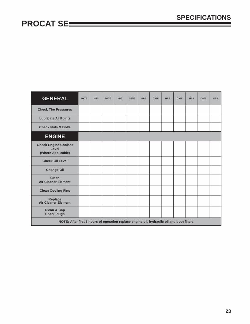
LARENEG ETAD SRH ETAD SRH ETAD SRH ETAD SRH ETAD SRH ETAD SRH
serusserPeriTkcehC
stnioPllAetacirbuL
stloB&stuNkcehC
ENIGNEtnalooCenignEkcehC
leveL)elbacilppAerehW(
leveLliOkcehC
liOegnahC
naelCtnemelErenaelCriA
sniFgnilooCnaelC
ecalpeRtnemelErenaelCriA
paG&naelCsgulPkrapS
.sretlifhtobdnaliociluardyh,lioenigneecalpernoitarepofosruoh5tsrifretfA:ETON

8
PROCAT SEMAINTENANCE
CHECK DAILY
Operator Presence Interlock System - Start OperationFor the engine to crank, the parking brake must be on, the PTO (blades) off and traction levers in the neutral lock position. Sit in the seat and check, one by one, if the engine will crank with the parking brake off, the blades on, and either traction lever out of neutral lock. Also, make sure engine coolant temperature gauge light flashes upon turning key to the ON position.
Operator Presence Interlock System - Run OperationThe operator must be in the seat for the engine to run with the parking brake off, the traction levers moved out of the neutral lock position, or the blades on. To check: 1. Start the engine and run at 1/2 throttle with the operator on the machine but raised off the seat. 2. One by one: move the parking brake to the OFF position, traction levers out of the neutral lock position
(check each independently), and turn the blades on. Each check should kill the engine after 1/2 second. (A 1/2 second delay is built into the system to prevent engine cutout when traversing rough terrain.)
Repair machine before using if the Operator Presence Interlock System does not operate correctly in start or run. Contact your authorized BOB-CAT dealer.
HardwareTighten any nuts and bolts found loose. Replace any broken or missing cotter pins. Repair any other problems before operating.
Tire pressureRear Tires should be kept inflated at 12 lbs/in2 (.84kg/cm2). Improper tire inflation can cause rapid tire wear and poor traction. Uneven inflation can cause uneven cutting. Front tires should be 15p.s.i. (1.05 kg/cm²)
BATTERY
Battery acid is caustic and fumes are explosive and can cause serious injury or death.
Use insulated tools, wear protective glasses or goggles and protective clothing when working with batteries. Read and obey the battery manufacturer’s instructions.
Be certain the ignition switch is OFF and the key has been removed before servicing the battery.
1. Verify battery polarity before connecting or dis-connecting the battery cables.
2. When installing the battery, always assemble the RED, positive ( + ) battery cable first and the ground, BLACK, negative ( - ) cable last.
3. When removing the battery, always remove the ground, negative ( - ) cable first and the red, posi-tive ( + ) cable last.
4. Check the electrolyte level every 100 hours of operation.
5. Clean the cable ends and battery posts with steel wool. Use a solution of baking soda and water to clean the battery. Do not allow the solution to enter into the battery cells.
6. Tighten cables securely to battery terminals and apply a light coat of silicone dielectric grease to terminals and cable ends to prevent corrosion. Keep terminal covers in place.

9
PROCAT SE
LUBRICATION
Every 50 hours of operation, lubricate the following points (1-4) with grease:1. Deck lift rockshaft (1 point)2. Deck lift pivots (6 points)3. Brake lever pivot (1 point)4. Push arms (2 points located at rear of cutterdeck under each fuel tank)5. Caster wheel pivots (2 points) (Lubricate every 500 hours or once a year)
NOTE ON BLADE SPINDLES - The blade spindles on these machines use a superior sealed bearing that does not require re-lubrication.
MAINTENANCE
2
5
22
3
5
2 2
4
4
1

10
PROCAT SEMAINTENANCE
HYDRAULIC SYSTEM
Fluid level in the hydraulic system should be checked after the first 5 hours of operation, and every 100 hours thereafter, or when a leak has occurred. If the fluid is low, check all components for leaks.
To check, remove reservoir cap M. The fluid level should be at the bottom of the filler tube. If low, top up (do not overfill). Use one of the oils listed below:
– SAE 15W40 motor oil– SAE 20W50 motor oil– 15W50 synthetic motor oil
AFTER FIRST FIVE (5) HOURS1. Remove plug N to drain hydraulic reservoir. Dis-
pose of used oil in accordance with local require-ments.
2. Clean and replace the plug. 3. Change hydraulic oil filter G. 4. Fill the reservoir with fresh oil to the bottom of
the reservoir filler tube, using an oil from the list above. Do not overfill.
PERIODIC OIL CHANGESChange the hydraulic fluid and hydraulic filter after each 500 hours of operation using the same procedure given above.
View from below machineNOTES:Before servicing the hydraulic system, stop the engine, disconnect spark plug wires and disengage the PTO. – After any hydraulic line is opened, plug or cap it
promptly to reduce the risk of contamination.– Do not use sealant tape on hydraulic pipe fittings.
Use a liquid sealant that will dissolve into the system.
– Make sure all hydraulic connections are tight and hydraulic hoses and lines are in good condition before applying pressure to system.
The machine's hydraulic system operates under high pressure. When checking for leaks, do not use your hands to attempt to find a leak. Instead, use card-board or paper. Escaping hydraulic fluid can be under sufficient pressure to penetrate skin and cause serious injury. If hydraulic fluid is injected into the skin, it must be promptly removed by a doctor familiar with this form of injury or gangrene may result.

11
PROCAT SEMAINTENANCE
SPARK PLUGS
Remove each plug and check condition. – Good operating conditions are indicated if the plug has a light coating of grey or tan deposit. – A white blistered coating indicates overheating. A black coating indicates an “over rich” fuel mixture. Both
may be caused by a clogged air cleaner or improper carburetor adjustment. – Do not sandblast, wire brush or otherwise attempt to repair a plug in poor condition. Best results are
obtained with a new plug.– Set plug gap as specified in engine manual..
ENGINE OILDo not perform engine maintenance without the engine off, spark plug wires disconnected and PTO disengaged.
AFTER FIRST FIVE (5) HOURSWhile the engine is warm:1. Release the oil drain hose assembly from the
engine clip J. Lay hose assembly over the frame edge.
2. Remove the rubber cap D from the tip of the hose assembly and turn the drain valve to allow oil to drain from the engine. Dispose of used oil in accordance with local requirements.
3. Clean drain valve and tighten the plastic portion of the drain valve back into the metal portion of the valve. Replace rubber cap over the tip of the valve. Replace hose assembly back into engine clip.
4. Change oil filter.
5. Fill the crankcase with fresh oil to the full mark. Do not overfill. See engine manual for oil specifications.
DAILY 1. Check oil level with the dipstick.2. If oil is needed, add fresh oil of proper
viscosity and grade. See engine manual for oil specifications. Do not overfill.
3. Replace dipstick before starting engine.
PERIODIC OIL CHANGES1. See engine manual for oil and filter change inter-
vals after the break-in period.2. Follow instructions for first oil change, above.

12
PROCAT SE
FUEL FILTERAn in line fuel filter is located in the fuel supply line. Inspect at every oil change to make sure it is clean and unobstructed. Replace if dirty.
MAINTENANCE
HEAVY DUTY CYCLONIC AIR CLEANERClean and replace the air cleaner element as specified in the service chart. Uneven running, lack of power or black exhaust fumes may indicate a dirty air cleaner.
To replace air cleaner elements:1. Unclamp end cover X and remove existing
cleaner elements.
2. Insert new elements Y and Z and replace cover. Ensure the breathing port A is pointing down and towards the front of the tractor.
ENGINE COOLINGContinued operation with a clogged cooling system will cause severe overheating and can result in en-gine damage.- Daily: Clean air intake screen S on air cooled
engines. - Every 100 hours: Clean cooling fins beneath
blower housing H with reference to information in the engine manufacturer's manual.

13
PROCAT SEMAINTENANCE
CLEANING MACHINEClean the machine after use. Compressed air is recommended. Do not use a pressure washer. The machine will run cooler and last longer if kept free of clippings and other debris. A clean machine also re-duces the risk of fire due to accumulation of combus-tible debris and chaff.
Brush or blow clippings and debris off the cutterdeck and engine deck. DO NOT use a pressure washer.
WASHING MACHINECAUTION: Improperly washing a machine can cause water to enter bearings and other components. This can greatly reduce component life.
– Do not use a pressure washer. Do not direct water at bearings or seals. High pressure water can blow past seals and enter sealed bearings.
– Allow the machine to cool down before washing. Water on a warm machine can be sucked into sealed bearings as they cool.
– Avoid getting electrical connections wet. Water can cause electrical faults and corrosion of elec-trical components.
14
PROCAT SEMAINTENANCE
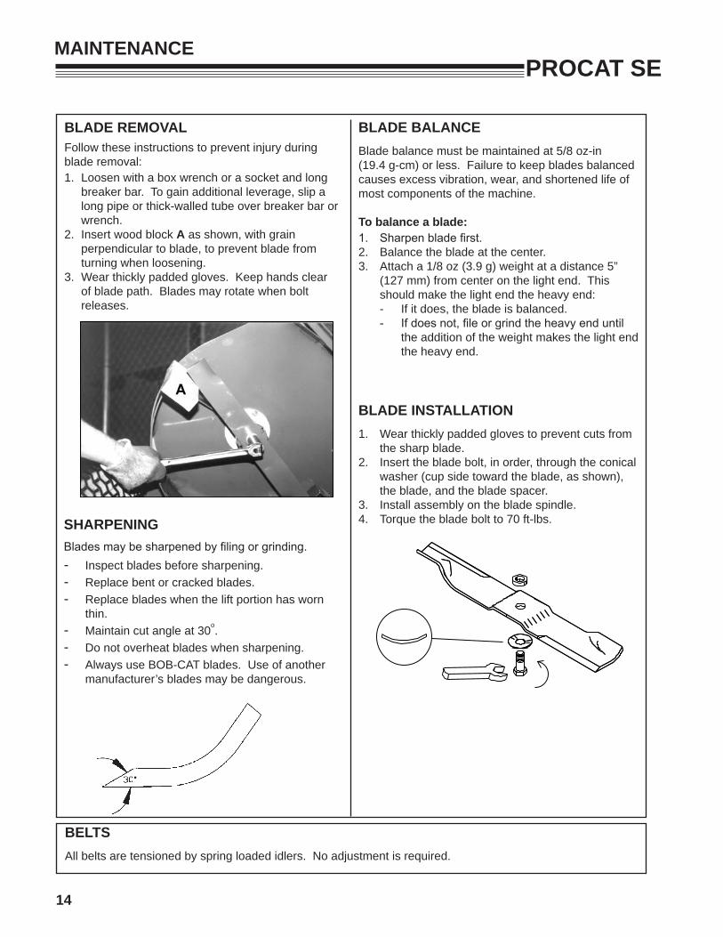
BLADE REMOVALFollow these instructions to prevent injury during blade removal:1. Loosen with a box wrench or a socket and long
breaker bar. To gain additional leverage, slip a long pipe or thick-walled tube over breaker bar or wrench.
2. Insert wood block A as shown, with grain perpendicular to blade, to prevent blade from turning when loosening.
3. Wear thickly padded gloves. Keep hands clear of blade path. Blades may rotate when bolt releases.
SHARPENINGBlades may be sharpened by filing or grinding. - Inspect blades before sharpening.- Replace bent or cracked blades.- Replace blades when the lift portion has worn
thin.- Maintain cut angle at 30o.- Do not overheat blades when sharpening. - Always use BOB-CAT blades. Use of another
manufacturer’s blades may be dangerous.
BLADE BALANCEBlade balance must be maintained at 5/8 oz-in (19.4 g-cm) or less. Failure to keep blades balanced causes excess vibration, wear, and shortened life of most components of the machine.
To balance a blade: 1. Sharpen blade first. 2. Balance the blade at the center.3. Attach a 1/8 oz (3.9 g) weight at a distance 5”
(127 mm) from center on the light end. This should make the light end the heavy end:
- If it does, the blade is balanced. - If does not, file or grind the heavy end until
the addition of the weight makes the light end the heavy end.
BLADE INSTALLATION1. Wear thickly padded gloves to prevent cuts from
the sharp blade.2. Insert the blade bolt, in order, through the conical
washer (cup side toward the blade, as shown), the blade, and the blade spacer.
3. Install assembly on the blade spindle. 4. Torque the blade bolt to 70 ft-lbs.
BELTSAll belts are tensioned by spring loaded idlers. No adjustment is required.

15
PROCAT SEADJUSTMENTS
DECK LEVELINGa) Park the machine on a smooth, level surface.
Raise the deck to the transport position.b) Lower the deck onto a pair of equal height blocks
A under the rear corners of the deck. Place another pair of adjustable blocks B under the front of the deck so that the deck top is pitched forward 1/8”.
A 1/8" forward pitched deck provides the best horse-power.A level deck provides the best quality of cut.A 1/8" rearward pitched deck provides the best strip-ing.Certain grass types and conditions may vary.
NOTE: The front and rear of the deck are at different heights.c) Measure the height of the blade cutting edge
above the ground. Remove pin C and set the height of cut lever D to that height.
d) Loosen nuts I at all four corners of the deck.NOTE: This will relieve tension on chains H.e) Loosen the jam nuts E on the height of cut clips
F and adjusting screws G. Turn the adjusting screws G until the play is taken out of the chains H at all four corners. Tighten the jam nuts E against the clips F and at the adjusting screws G. Retighten nuts I at this time.
FORWARD PITCH SHOWN
16
PROCAT SEADJUSTMENTS
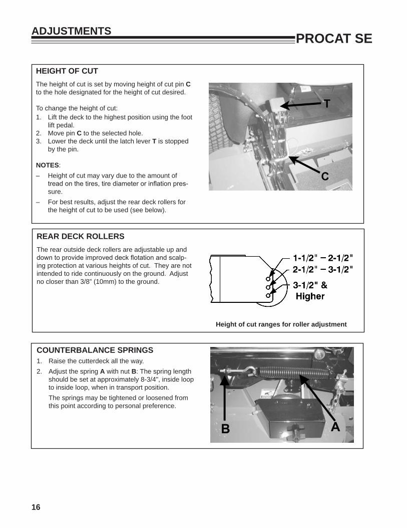
REAR DECK ROLLERS The rear outside deck rollers are adjustable up and down to provide improved deck flotation and scalp-ing protection at various heights of cut. They are not intended to ride continuously on the ground. Adjust no closer than 3/8” (10mm) to the ground.
Height of cut ranges for roller adjustment
HEIGHT OF CUTThe height of cut is set by moving height of cut pin C to the hole designated for the height of cut desired.
To change the height of cut:1. Lift the deck to the highest position using the foot
lift pedal.2. Move pin C to the selected hole. 3. Lower the deck until the latch lever T is stopped
by the pin.
NOTES: – Height of cut may vary due to the amount of
tread on the tires, tire diameter or inflation pres-sure.
– For best results, adjust the rear deck rollers for the height of cut to be used (see below).
COUNTERBALANCE SPRINGS 1. Raise the cutterdeck all the way.2. Adjust the spring A with nut B: The spring length
should be set at approximately 8-3/4", inside loop to inside loop, when in transport position.The springs may be tightened or loosened from this point according to personal preference.

17
PROCAT SEADJUSTMENTS
PARKING BRAKEPark machine on a smooth level surface.Support the machine with the rear wheels off the ground, using jack stands or equivalent. DO NOT rely on mechanical or hydraulic jacks.1. Remove rear wheels. 2. Measure spring length O with parking brake N in
the OFF position. 3. Move parking brake N to the ON position and
measure length of spring O again. When spring deflects 3/8" it is properly adjusted.
4. If adjustment is required, return parking brake N to the OFF position.
5. Disconnect one end of rod M at the brake and loosen jam nut.
6. Adjust rod M in or out as required until 3/8" de-flection in brake spring O is achieved with park-ing brake N in the ON position.
7. Reconnect rod M and retighten jam nut.8. Repeat steps 2-7 on opposite side of machine.9. Replace wheels and tighten wheel nuts.
Parking brake assembly (tire and deck not shown for clarity - brake in ON position).
This adjustment will cause the brake springs to stretch 3/8" when the parking brake is in the ON posi-tion, providing the correct parking brake force without overloading the brake arm.
NOTE: Parking brake must be in the OFF position to properly seat brake drums.
CONTROL LEVERSThere are two mounting positions for the control levers, upper and lower. The lower position works well for most people. Taller operators may need the upper position.
To adjust the height of the control levers:- Remove bolts and nuts A. - Align holes in control lever C with appropriate
holes in traction lever bracket B.- Install bolts and nuts A.
The upper mounting hole for the control levers is slotted to allow fore-aft adjustment and to allow alignment of the levers.
To adjust or align the control levers:- Loosen nuts A. - Adjust control lever position.- Tighten nuts A.

18
PROCAT SE
TRACKING HANDLESAn adjustment is provided to allow the operator to adjust machine tracking during operation.
1. Turn knob W clockwise to shorten control lever travel.
2. Turn knob W counter-clockwise to increase con-trol lever travel.
FRONT DECK LIPAdjustable front deck lips have been provided on 48in., 52 in. and 61 in. cutterdecks for various cutting conditions.
To revise per conditions:1. Loosen the front bolts S.2. Adjust height of H. 3. Retighten S once you have desired height.
ADJUSTMENTS
DAMPERSDifferent damper mounting holes have been provided for various operator preferences with control lever motion.
1. For a stronger resistance feel, mount the damp-ers X in the outer most hole Z of the motion control weldment.
2. For a lighter resistance feel, mount the dampers X in the inner most hole V of the motion control weldment.

19
PROCAT SEADJUSTMENTS
HYDROSTAT ADJUSTMENTSA turnbuckle-style hydrostat neutral adjustment is provided.
Neutral: 1. Support the machine with the rear wheels off
the ground. Use jackstands or equivalent sup-port. Do not rely only on mechanical or hydraulic jacks.
2. Move the traction levers out into the neutral lock position and raise the seat.
3. Disconnect the seat switch wire K and temporarily connect the two terminals with jumper wire J as shown.
4. Start the engine and run at low speed. 5. Loosen jam nuts T at both ends of the control
rod. 6. Rotate the control rod until the corresponding
wheel stops turning. Lock the jam nuts. Run the engine up to high idle to check the adjustment. Readjust if necessary.
7. Repeat steps 5 and 6 for the opposite side.8. Remove the jumper wire J and reconnect the
seat switch.Reverse Return:1. Move traction levers out to the neutral lock posi-
tion and raise the seat.2. Locknut U should be run on the bolt as far as it
will go.3. Loosen jam nut Y. Adjust the clevis yoke by
turning the head of the bolt until the clevis pin just makes contact with the rear of the slot in the lever it connects with. Tighten jam nut Y.
4. Repeat steps 2 and 3 for the opposite side.
NOTE: A slight creep in reverse is acceptable provided the wheel does not turn and the hydrostat pump does not whine when the parking brake is on.
Right side adjustments

20
PROCAT SEBELT REPLACEMENT
Note: Always use Schiller Grounds Care, Inc.replacement belts, not general purpose belts. Schiller Grounds Care, Inc.belts are specially designed for use on commercial mow-ers and will normally last longer.
CUTTERDECK BELT
1. Tilt floorplate all the way forward.2. Set the cutterdeck in a middle height-of-cut posi-
tion. 3. Use a 3/8" ratchet and extension to back
tensioning idler off to remove belt from idler. Remove belt from cutterdeck pulleys.
NOTE: Use the 3/8" ratchet in the square hole A on the idler.
4. Remove belt from clutch pulley. 5. Install the new belt by performing these steps in
reverse order.6. If machine has eyebolt for adjusting belt ten-
sioning spring, adjust eyebolt so the distance between the outside of the spring post on the movable idler and the inside of the eyebolt is 10-3/4±1/8".
NOTE: After usage of the machine, the belt will seat into the pulleys and reduce thelength of the spring. DO NOT READJUST THE EYEBOLT. This is normal. If you do adjust the eyebolt, you will over tension the belt, greatly reducing it life.
A
PUMP-DRIVE BELT1. Remove engine-cutterdeck belt (see engine-
cutterdeck belt replacement). 2. Attach an extension to a 3/8" drive ratchet. Insert
the ratchet extension in the square hole of the pump drive idler arm. Use the ratchet handle to rotate it enough to remove the pump drive belt.
3. Install a new pump drive belt in the same manner as it was removed.
4. Re-install engine-cutterdeck belt (see engine-cutterdeck belt replacement).
1034"±1
8"
- SPRING LENGTH FOR WHEN INSTALLING NEW BELTS ONLY- DO NOT READJUST AFTER USE
4169712
21
PROCAT SE
POWER UNITS
ENGINES: Construction: Aluminum block with cast-in cast iron sleeves. Aluminum head.Configuration: 4-stroke, vertical shaft, V-twin cylin-der, overhead valve, air-cooled.
DRIVE SYSTEM:Full hydrostatic pump and wheel motor combination for independently controlled drive wheels.Pump: Hydrogear 12cc variable displacement piston pump.Motors: Parker displacement MB series. Direct drive 1-1/4” (31.8mm) diameter output shaft.Turn Radius: True Zero
OPERATOR PRESENCE INTERLOCK SYSTEM:Start: The PTO (blades) must be off, traction levers in neutral lock, and parking brake on for engine to crank.Run: Operator must be in seat to take parking brake off, to move traction levers out of the neutral lock position, or to turn the PTO (blades) on or the engine will kill. The parking brake must be off for the traction levers to move out of the neutral lock position.The operator may leave the seat with the engine running if the parking brake is on, the PTO (blades) is off, and the traction levers are in the neutral lock position. A time delay eliminates annoying engine cutout from operation over rough terrain.
WEIGHT:
1256 lbs (570 kg) w/52" deck1293 lbs (587 kg) w/61" deck
CONTROLS:Throttle; choke; power takeoff (PTO) clutch switch; traction levers; parking brake lever; lift lever.
FUEL SYSTEM:One tank on each side of operator, each with a shut-off (1/4 turn). Total capacity 14 gallons (52.9 liters). Fuel selector/shutoff switch on rear cooler mounting bracket(1/4 turn). Replaceable fuel filter.
MAXIMUM GROUND SPEEDS:Forward: 11.5 mph (18.5 km/h)Reverse: 4 mph (6.4 km/h)
WHEELS & TIRES:Drive wheels: 942520J: 23 X 10.5-12 4-Ply Turf 942522J Tread Tires
942521J: 24 X 12.00-12 4-Ply Turf 942523J Tread Tires
Casters:52", 61", : 13 X 6.5-6 tires Pressure: Rear tires 12 p.s.i. (.84 kg/cm2) Front tires 15 p.s.i. (1.05 kg/cm²)
BRAKING:Parker brakes. Spring applied for overload protection.
SEAT:High back, foam padded seat with standard armrests. Fore and aft adjusters, hinged for easy tilt-up access to pumps and battery. Internally mounted seat switch.
SPECIFICATIONS

22
PROCAT SESPECIFICATIONS
ENGINESMODEL NUMBER 942520J 942521J 942522J 942523JMANUFACTURER Kohler Kohler Kawaskai Kawasaki
MODEL CV680 CV680 FX651V FX730V
CYLINDERS 2 2 2 2
COOLING Air Air Air Air
BORE/STROKE 3.2 X 2.6"(80 X 67 mm)
3.27 X 2.64"(83 X 67 mm)
3.1 X 3.0"(80 X 67 mm)
3.1 X 3.0"(80 X 67 mm)
DISPLACEMENT 41.1 cu. in.(674 cc)
44 cu. in.(725 cc)
44.3 cu. in.(726 cc)
44.3 cu. in.(726 cc)
COMPRESSION 8.5:1 9.1:1 8.2:1 8.2:1
OUTPUT POWER Refer to engine manufacturer's specifications and/or website.
OUTPUT TORQUE 36.1 ft-lb (48.9J)@2400 rpm
42 ft-lb (457.9J)@2800 rpm
40.0 ft-lb (54.2J)@2200 rpm
42.1 ft-lb (55.4J)@2400 rpm
LUBRICATION FULL PRESSURE FULL PRESSURE FULL PRESSURE FULL PRESSURE
GOVERNOR Mechanical Mechanical Mechanical Mechanical
AIR CLEANER Heavy Duty Cyclonic Heavy Duty Cyclonic Heavy Duty Cyclonic Heavy Duty Cyclonic
IGNITION SYSTEM Electronic Electronic Electronic Electronic
CHARGING SYSTEM 15 amp, regulated 15 amp, regulated 15 amp, regulated 15 amp, regulated
BATTERY BCI group U1 BCI group U1 BCI group U1 BCI group U1
FUSES Two, 20 amp blade Two, 20 amp blade Two, 20 amp blade Two, 20 amp blade
FUEL CONSUMP-TION @ MAX LOAD/SPEED
23
PROCAT SESPECIFICATIONS
LARENEG ETAD SRH ETAD SRH ETAD SRH ETAD SRH ETAD SRH ETAD SRH
serusserPeriTkcehC
stnioPllAetacirbuL
stloB&stuNkcehC
ENIGNEtnalooCenignEkcehC
leveL)elbacilppAerehW(
leveLliOkcehC
liOegnahC
naelCtnemelErenaelCriA
sniFgnilooCnaelC
ecalpeRtnemelErenaelCriA
paG&naelCsgulPkrapS
.sretlifhtobdnaliociluardyh,lioenigneecalpernoitarepofosruoh5tsrifretfA:ETON
24
PROCAT SESPECIFICATIONS
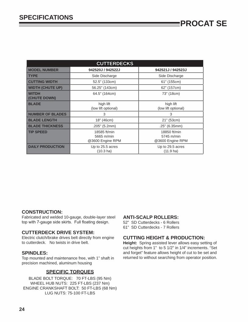
CONSTRUCTION:Fabricated and welded 10-gauge, double-layer steel top with 7-gauge side skirts. Full floating design.
CUTTERDECK DRIVE SYSTEM:Electric clutch/brake drives belt directly from engine to cutterdeck. No twists in drive belt.
SPINDLES:Top mounted and maintenance free, with 1” shaft in precision machined, aluminum housing
ANTI-SCALP ROLLERS:52” SD Cutterdecks - 6 Rollers61” SD Cutterdecks - 7 Rollers
CUTTING HEIGHT & PRODUCTION:Height: Spring assisted lever allows easy setting of cut heights from 1" to 5 1/2" in 1/4” increments. “Set and forget” feature allows height of cut to be set and returned to without searching from operator position.
SPECIFIC TORQUESBLADE BOLT TORQUE: 70 FT-LBS (95 Nm)WHEEL HUB NUTS: 225 FT-LBS (237 Nm)
ENGINE CRANKSHAFT BOLT: 50 FT-LBS (68 Nm)LUG NUTS: 75-100 FT-LBS
CUTTERDECKSMODEL NUMBER 942520J / 942522J 942521J / 942523JTYPE Side Discharge Side DischargeCUTTING WIDTH 52.5" (133cm) 61" (155cm)WIDTH (CHUTE UP) 56.25" (143cm) 62" (157cm)WITDH(CHUTE DOWN)
64.5" (164cm) 73" (18cm)
BLADE high lift(low lift optional)
high lift(low lift optional)
NUMBER OF BLADES 3 3BLADE LENGTH 18" (46cm) 21" (53cm)BLADE THICKNESS .205" (5.2mm) .25" (6.35mm)TIP SPEED 18585 ft/min
5665 m/min@3600 Engine RPM
18850 ft/min5745 m/min
@3600 Engine RPMDAILY PRODUCTION Up to 25.5 acres
(10.3 ha)Up to 29.5 acres
(11.9 ha)

25
PROCAT SEPARTS SECTION
PARTS SECTION
26
PROCAT SEFIGURE 1
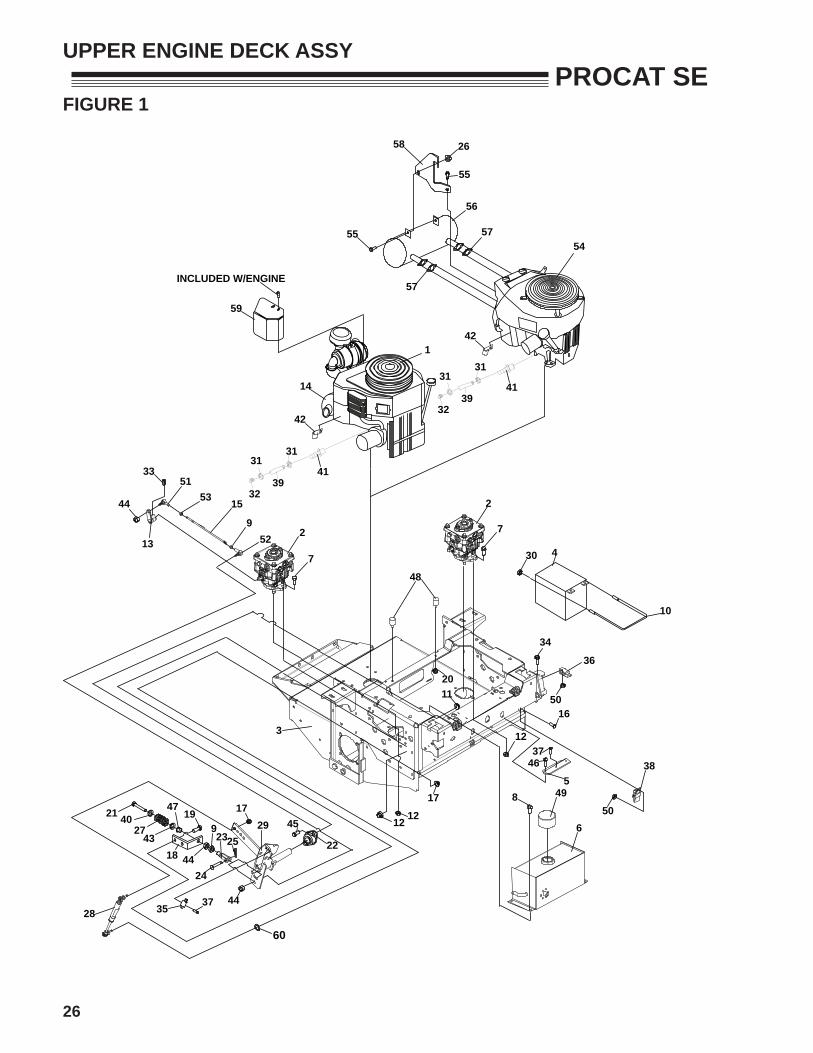
UPPER ENGINE DECK ASSY
38
12
465
16
37
923
192127
43
28
40
24
35
18 44
47 174529
22
44
31
32
31
3941
42
14
1
34
5011
17
12 12
2
7
7
2
48
36
49
6
8
37
3
25
20
50
13
44
33
15
5153
952
57
42
31
58
55
26
57
56
55
54
39
3141
32
30 4
10
59
INCLUDED W/ENGINE
60
27
PROCAT SE
ITEM PART NO. DESCRIPTION QTY ITEM PART NO. DESCRIPTION QTY
* NOT ILLUSTRATED
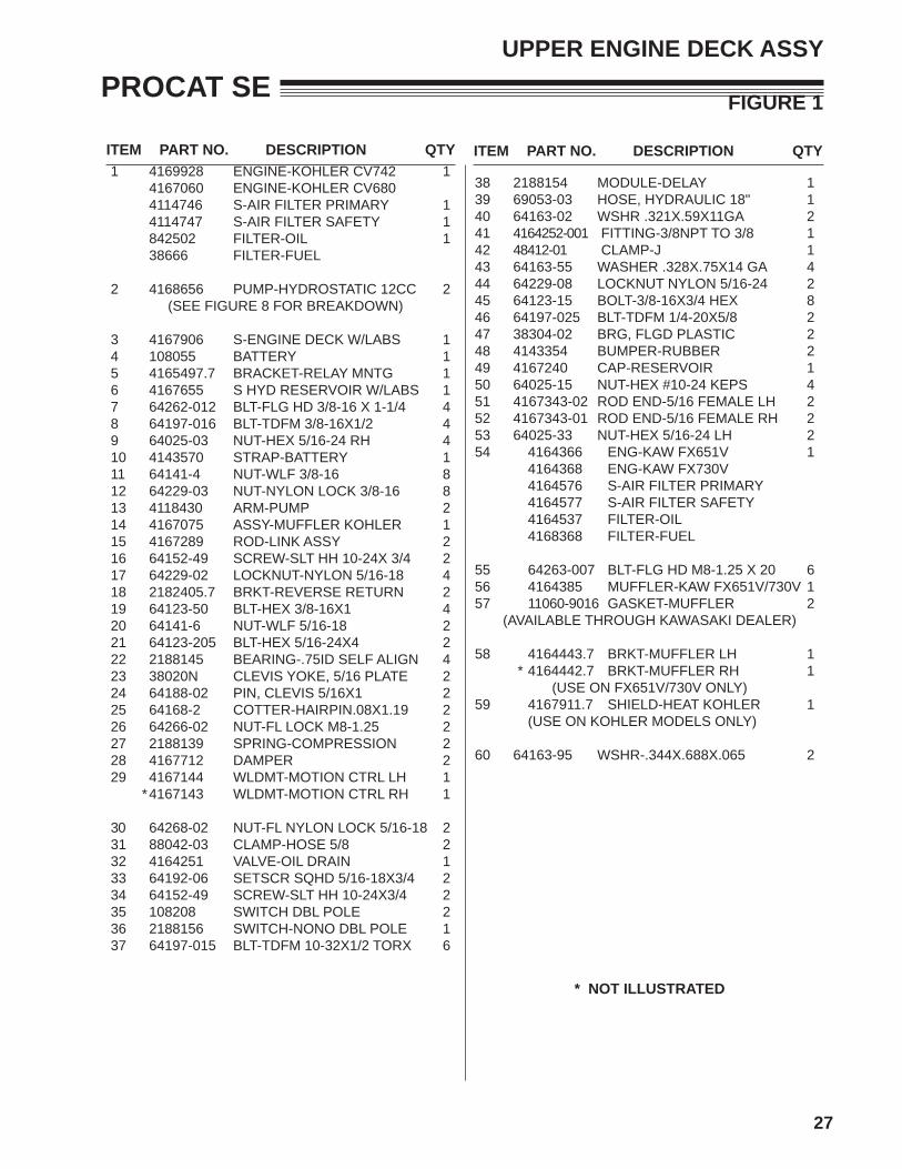
1 4169928 ENGINE-KOHLER CV742 14167060 ENGINE-KOHLER CV6804114746 S-AIR FILTER PRIMARY 14114747 S-AIR FILTER SAFETY 1842502 FILTER-OIL 138666 FILTER-FUEL
2 4168656 PUMP-HYDROSTATIC 12CC 2(SEE FIGURE 8 FOR BREAKDOWN)
3 4167906 S-ENGINE DECK W/LABS 14 108055 BATTERY 15 4165497.7 BRACKET-RELAY MNTG 16 4167655 S HYD RESERVOIR W/LABS 17 64262-012 BLT-FLG HD 3/8-16 X 1-1/4 48 64197-016 BLT-TDFM 3/8-16X1/2 49 64025-03 NUT-HEX 5/16-24 RH 410 4143570 STRAP-BATTERY 111 64141-4 NUT-WLF 3/8-16 812 64229-03 NUT-NYLON LOCK 3/8-16 813 4118430 ARM-PUMP 214 4167075 ASSY-MUFFLER KOHLER 115 4167289 ROD-LINK ASSY 216 64152-49 SCREW-SLT HH 10-24X 3/4 217 64229-02 LOCKNUT-NYLON 5/16-18 418 2182405.7 BRKT-REVERSE RETURN 219 64123-50 BLT-HEX 3/8-16X1 420 64141-6 NUT-WLF 5/16-18 221 64123-205 BLT-HEX 5/16-24X4 222 2188145 BEARING-.75ID SELF ALIGN 423 38020N CLEVIS YOKE, 5/16 PLATE 224 64188-02 PIN, CLEVIS 5/16X1 225 64168-2 COTTER-HAIRPIN.08X1.19 226 64266-02 NUT-FL LOCK M8-1.25 227 2188139 SPRING-COMPRESSION 228 4167712 DAMPER 229 4167144 WLDMT-MOTION CTRL LH 1 * 4167143 WLDMT-MOTION CTRL RH 1
30 64268-02 NUT-FL NYLON LOCK 5/16-18 231 88042-03 CLAMP-HOSE 5/8 232 4164251 VALVE-OIL DRAIN 133 64192-06 SETSCR SQHD 5/16-18X3/4 234 64152-49 SCREW-SLT HH 10-24X3/4 235 108208 SWITCH DBL POLE 236 2188156 SWITCH-NONO DBL POLE 137 64197-015 BLT-TDFM 10-32X1/2 TORX 6
FIGURE 1
UPPER ENGINE DECK ASSY
38 2188154 MODULE-DELAY 139 69053-03 HOSE, HYDRAULIC 18" 140 64163-02 WSHR .321X.59X11GA 241 4164252-001 FITTING-3/8NPT TO 3/8 142 48412-01 CLAMP-J 143 64163-55 WASHER .328X.75X14 GA 444 64229-08 LOCKNUT NYLON 5/16-24 245 64123-15 BOLT-3/8-16X3/4 HEX 846 64197-025 BLT-TDFM 1/4-20X5/8 247 38304-02 BRG, FLGD PLASTIC 248 4143354 BUMPER-RUBBER 249 4167240 CAP-RESERVOIR 150 64025-15 NUT-HEX #10-24 KEPS 451 4167343-02 ROD END-5/16 FEMALE LH 252 4167343-01 ROD END-5/16 FEMALE RH 253 64025-33 NUT-HEX 5/16-24 LH 254 4164366 ENG-KAW FX651V 1 4164368 ENG-KAW FX730V 4164576 S-AIR FILTER PRIMARY 4164577 S-AIR FILTER SAFETY 4164537 FILTER-OIL 4168368 FILTER-FUEL
55 64263-007 BLT-FLG HD M8-1.25 X 20 656 4164385 MUFFLER-KAW FX651V/730V 157 11060-9016 GASKET-MUFFLER 2
(AVAILABLE THROUGH KAWASAKI DEALER)
58 4164443.7 BRKT-MUFFLER LH 1 * 4164442.7 BRKT-MUFFLER RH 1
(USE ON FX651V/730V ONLY)59 4167911.7 SHIELD-HEAT KOHLER 1 (USE ON KOHLER MODELS ONLY)
60 64163-95 WSHR-.344X.688X.065 2

28
PROCAT SEFIGURE 2
LOWER ENGINE DECK ASSY/CLUTCH
9
PUMP
ENGINE
PUMP
26
12
4
328
27
1
24
20 1418
22
9
3117
15
19
16
10
13
27283
1
29
25
BELT DETAIL
5
14
1
23
5
6
2
2
1
7
8
32
11
9
30
21
33

29
PROCAT SE
ITEM PART NO. DESCRIPTION QTY ITEM PART NO. DESCRIPTION QTY
FIGURE 2
LOWER ENGINE DECK ASSY/CLUTCH
11 4158360 PULLEY-PUMP 22 64044-18 SCREW-SET 1/4-20 X 5/16 43 64238-03 KEY-MET 5MM SQX28MM 24 64164-12 KEY 15 4165509 PULLEY- 5.25 OD X 1.126 16 4165689 CLUTCH-ELECTRIC, 225 17 4165570.7 WLDMT-CLUTCH STOP 18 4121540 PIN-CLUTCH 19 64006-03 LOCKWSHR-3/8 HELICAL 610 64123-54 BLT-HEX 5/16-18X3/4 211 64123-70 BLT-HEX 3/8-16X1-1/2 412 64006-06 LCKWSHER-HELICAL 7/16 113 64268-02 NUT-FL NYLON LCK 5/16-18 214 2308000 PULLEY-IDLER 4.00 EOD 115 4128923 S-ASSY-IDLER ARM PUMP 1 (INCLUDES ITEMS 16, 18 & 24)
16 4127999 SEAL 117 64270-01 BOLT-MET HEX M10-1.5X30 118 4128004 BEARING 119 33148-01 SPACER-0.379X0.750X0.25 120 2188131 SPRING-EXTENSION 121 64262-006 BLT-5/16-18X1 222 64123-21 BLT-HEX 3/8-24X1-1/4 123 4167906 S-ENGINE DECK W/LABS 1 (INCLUDES ITEMS 34 & 35)
24 64144-40 SNAP RING 125 4157920 BELT PUMP DRIVE 126 64123-216 BLT-HEX 7/16-20X2-1/4 127 64205-013 BLT-MET M6-1X12 228 64209-09 WASHER-CONICAL SPRING 229 2720949 ASSY-CLUTCH WIRE 130 64123-15 BLT-HEX 3/8-16X3/4 131 4128002 END CAP 132 38304-03 BEARING-FLNGD PLASTIC 133 4166355 PIN-BELT GUIDE 2

30
PROCAT SEFIGURE 3
BUMPER
1
2
3
4
4
6
6
6
5
5 5
5
66

31
PROCAT SE
ITEM PART NO. DESCRIPTION QTY ITEM PART NO. DESCRIPTION QTY
1 4167906 S-ENG DECK W/LABS 1 2 4165491.7 BRKT-BUMPER, TOP 1 3 4165490.7 WRAPPER-BUMPER 1 4 4165492.7 STRAP-BUMPER 2 5 64262-012 BLT-FLG HD 3/8-16 X 1-1/4 126 64268-03 NUT-FL NYLON LOCK 3/8-16 12
FIGURE 3
BUMPER

32
PROCAT SEFIGURE 4
FUEL TANKS/CONTROL PANEL
1
2
4
26
6
1718
17
18
9
20
20
9
9
33
15
5
32
319
16
30
916
9
16
31
32
3315
38
142729
122524
8
10
7 11 13
19
TO ENGINE

33
PROCAT SE
ITEM PART NO. DESCRIPTION QTY ITEM PART NO. DESCRIPTION QTY
FIGURE 4
FUEL TANKS/CONTROL PANEL
1 4165428 TANK-FUEL LH 1(INCLUDES ITEMS 15, 31-33, 35, 36, 37)
2 4165429 TANK-FUEL RH 1(INCLUDES ITEMS15, 31-33, 35, 36, 37)
3 4165930 S-CONTROL PANEL 14 4167906 S ENG DECK W/LABS 15 4165291 CAP-FUEL, RATCHET TYPE 26 64123-50 BLT-HEX 3/8-16X1 87 2188178 SWITCH-RETAINER 18 64262-001 BLT-FLG HD 1/4-20 X 1/2 49 88042N HOSE CLAMP 1210 128010 KEY-SWITCH 111 118020-16 CONTROL-THROTTLE 48.0 112 2721505 SWITCH-PTO 113 64025-15 NUT-HEX #10-24 KEPS 214 64152-46 SCR.-SLT HH #10-24X1/2 215 4132325 GROMMET-FUEL TANK 216 4162977-020 HOSE,.25IDX.50OD 317 64006-03 LOCKWSHR-3/8 HELICAL 818 64163-31 WSHR 25/64X1X12 819 2188161 VALVE-TANK SELECTOR 120 4162977-001 HOSE,.25IDX.50OD X 321* 4165692-01 FUEL-LINE TANK 222* 4165668 FILTER-FUEL 223* 4166704 CLAMP-FUEL 224 128010-01 S-KEY SWITCH NYLON NUT 125 128010-03 S-COVERED KEY 126 4167193 PLUG-PLASTIC 127 108009-03 CONTROL-CHOKE 51" 128* 64025-04 NUT-3/8-24 HEX (CHOKE) 129 4165120 METER-HOUR 130 4165863 TEE-FITING 1/4" HOSE 131 4165763 ROLL-OVER VENT 232 4165387 GROMMET-ROLL OVER 233 4165667 FITTING-BARBED 90 DEG 234* 970391 KIT-LIGHT ACCESSORY 1
*NOT ILLUSTRATED

34
PROCAT SEFIGURE 5
BRAKES/REAR WHEEL
310
17
11
31
19
26225 FT/LBSTORQUE TO
2423
25
1
22
1614
278
24
17
7
628
13
15
19
12
9
5
1827
27
30
27
21
20
29 32
35
PROCAT SE
ITEM PART NO. DESCRIPTION QTY ITEM PART NO. DESCRIPTION QTY
FIGURE 5
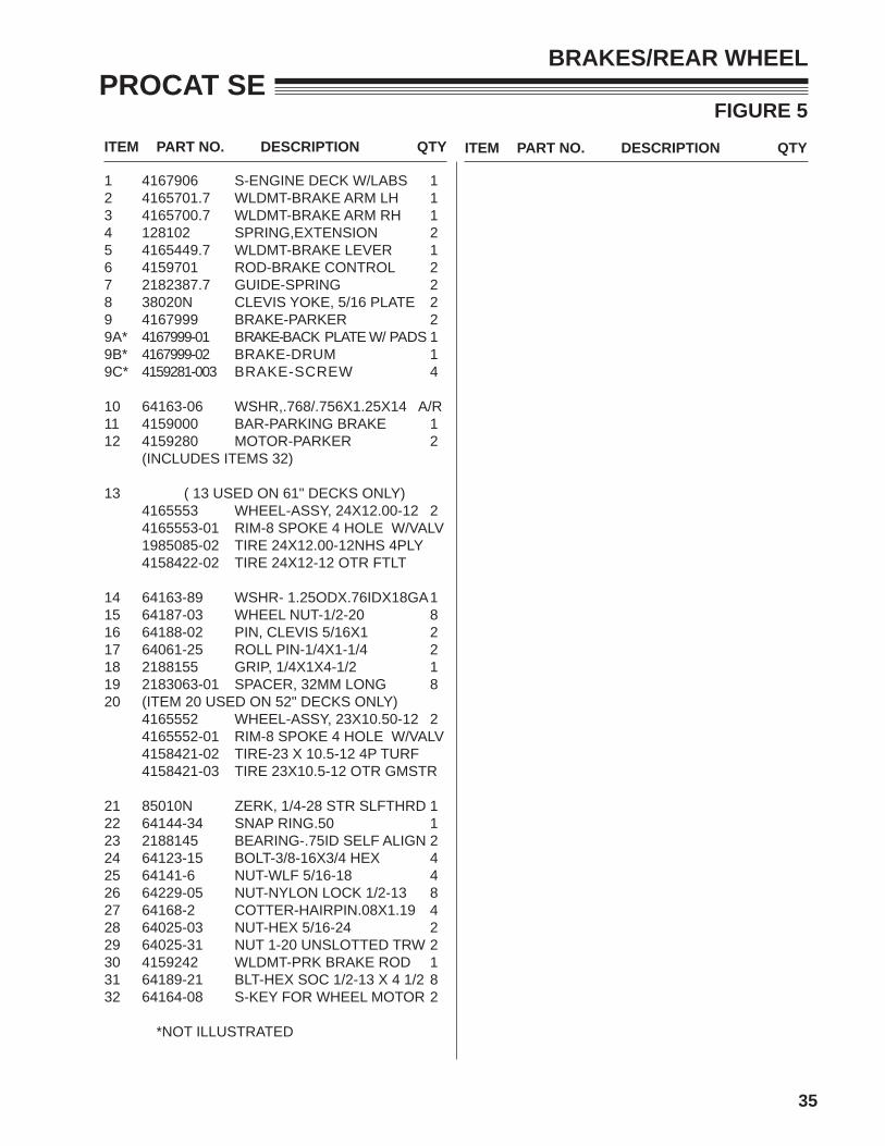
BRAKES/REAR WHEEL
1 4167906 S-ENGINE DECK W/LABS 12 4165701.7 WLDMT-BRAKE ARM LH 13 4165700.7 WLDMT-BRAKE ARM RH 14 128102 SPRING,EXTENSION 25 4165449.7 WLDMT-BRAKE LEVER 16 4159701 ROD-BRAKE CONTROL 27 2182387.7 GUIDE-SPRING 28 38020N CLEVIS YOKE, 5/16 PLATE 29 4167999 BRAKE-PARKER 29A* 4167999-01 BRAKE-BACK PLATE W/ PADS 19B* 4167999-02 BRAKE-DRUM 19C* 4159281-003 BRAKE-SCREW 4
10 64163-06 WSHR,.768/.756X1.25X14 A/R11 4159000 BAR-PARKING BRAKE 112 4159280 MOTOR-PARKER 2
(INCLUDES ITEMS 32)
13 ( 13 USED ON 61" DECKS ONLY)4165553 WHEEL-ASSY, 24X12.00-12 24165553-01 RIM-8 SPOKE 4 HOLE W/VALV1985085-02 TIRE 24X12.00-12NHS 4PLY4158422-02 TIRE 24X12-12 OTR FTLT
14 64163-89 WSHR- 1.25ODX.76IDX18GA 115 64187-03 WHEEL NUT-1/2-20 816 64188-02 PIN, CLEVIS 5/16X1 217 64061-25 ROLL PIN-1/4X1-1/4 218 2188155 GRIP, 1/4X1X4-1/2 119 2183063-01 SPACER, 32MM LONG 820 (ITEM 20 USED ON 52" DECKS ONLY)
4165552 WHEEL-ASSY, 23X10.50-12 24165552-01 RIM-8 SPOKE 4 HOLE W/VALV4158421-02 TIRE-23 X 10.5-12 4P TURF4158421-03 TIRE 23X10.5-12 OTR GMSTR
21 85010N ZERK, 1/4-28 STR SLFTHRD 122 64144-34 SNAP RING.50 123 2188145 BEARING-.75ID SELF ALIGN 224 64123-15 BOLT-3/8-16X3/4 HEX 425 64141-6 NUT-WLF 5/16-18 426 64229-05 NUT-NYLON LOCK 1/2-13 827 64168-2 COTTER-HAIRPIN.08X1.19 428 64025-03 NUT-HEX 5/16-24 229 64025-31 NUT 1-20 UNSLOTTED TRW 230 4159242 WLDMT-PRK BRAKE ROD 131 64189-21 BLT-HEX SOC 1/2-13 X 4 1/2 832 64164-08 S-KEY FOR WHEEL MOTOR 2
*NOT ILLUSTRATED

36
PROCAT SEFIGURE 6
OIL COOLER
114
14
14
1413
11
15
14
1311
15
12
9 7B 9
TO PUMP CASE DRAIN
9
7A9
618
16
218
18
3
10
2
20
15
19
10
17
218
4
5
22
23

37
PROCAT SE
ITEM PART NO. DESCRIPTION QTY ITEM PART NO. DESCRIPTION QTY
1 4167906 S ENGINE DECK W/LABS 12 4166418.7 BRKT-COOLER FRONT 1
(USED ON 942522J & 942523J)4168913.7 BRKT-COOLER FRONT(USED ON 942520J & 942521J)
3 64262-002 BLT-FLG HD 1/4-20 X 3/4 44 2720891.7 SCREEN-OIL COOLER 15 2188173 COOLER-OIL 16 4167655 S HYD RSRVR W/LABS 1
(69053-05 IS A SERVICEABLE LENGTH OF 55")7A 69053-05 3/8 HIGH TEMP HOSE 17B 69053-05 3/8 HIGH TEMP HOSE 1
8 48412-01 CABLE-CLIP N 29 88042-04 CLAMP-3/4 CLIP 410 64163-03 WSHR .256X.62X18GA 211 4165492.7 ARM-BUMPER 212 64229-01 NUT-NYLON LOCK 1/4-20 413 4169246.7 BRKT-COOLER REAR 214 64268-03 NUT-FL NYLON LOCK 3/8-16 815 64262-012 BLT-FLG HD 3/8-16 X 1-1/4 616 4165752 CLAMP-HOSE, 5/8IN 117 4165751 CLAMP-HOSE, 1/2IN 118 64229-01 NUT-NYLON LOCK 1/4-20 219 64123-07 BLT-HEX 1/4-20X1-1/2 120 64123-60 BLT-HEX 1/4-20X2 121 64262-011 BLT-FLG HD 3/8-16X1 222 4143354 BUMPER-RUBBER 223 64141-6 NUT-WLF 5/16-18 4
FIGURE 6
OIL COOLER

38
PROCAT SEFIGURE 7
AIR COOLED HYDRAULICS
13 7
13
713
1
16
3
2
7
1313
18
15
15
11
14
5
18
6
610
9
8
106
6
1420
5
1319
111815
15
15
15
61312
7
13
9 / 23
8 / 22
17
21
21
39
PROCAT SE
ITEM PART NO. DESCRIPTION QTY ITEM PART NO. DESCRIPTION QTY
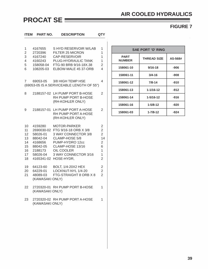
1 4167655 S HYD RESERVOIR W/LAB 12 2720396 FILTER 25 MICRON 13 4167240 CAP-RESERVOIR 14 4160243 PLUG-HYDRAULIC TANK 15 158058-04 FTG-90 BRB 9/16-18X.38 26 108205-03 ELBOW-MALE 45 37-ORB 4
7 69053-05 3/8 HIGH TEMP HSE 4(69053-05 IS A SERVICEABLE LENGTH OF 55")
8 2188157-02 LH PUMP PORT B-HOSE 2RH PUMP PORT B-HOSE (RH-KOHLER ONLY)
9 2188157-01 LH PUMP PORT A-HOSE 2RH PUMP PORT A-HOSE(RH-KOHLER ONLY)
10 4159280 MOTOR-PARKER 211 2690030-02 FTG 9/16-18 ORB X 3/8 212 58026-01 3 WAY CONNECTOR 3/8 213 88042-04 CLAMP-HOSE 5/8 1414 4168656 PUMP-HYDRO 12cc 215 88042-05 CLAMP-HOSE 13/16 616 2188173 OIL COOLER 117 58026-04 3 WAY CONNECTOR 3/16 118 4165341-02 HOSE-HYDR, 2
19 64123-60 BOLT, 1/4-20X2 HEX 220 64229-01 LOCKNUT-NYL 1/4-20 221 48089-03 FTG-STRAIGHT 8 ORB X 8 2
(KAWASAKI ONLY)
22 2720320-01 RH PUMP PORT B-HOSE 1(KAWASAKI ONLY)
23 2720320-02 RH PUMP PORT A-HOSE 1(KAWASAKI ONLY)
FIGURE 7
AIR COOLED HYDRAULICS
GNIR'O'TROPEAS
TRAPREBMUN EZISDAERHT #865-SA
01-160851 81-61/9 609-
11-160851 61-4/3 809-
21-160851 41-8/7 019-
31-160851 21-61/1-1 219-
41-160851 21-61/5-1 619-
61-160851 21-8/5-1 029-
30-160851 21-8/7-1 429-
40
PROCAT SEFIGURE 8
HYDROGEAR PUMP
10
78
44
6
2
456
5742
A
52529
3034
323 38
371
49
1821
20
22
42B
15
41
PROCAT SEFIGURE 8
HYDROGEAR PUMP
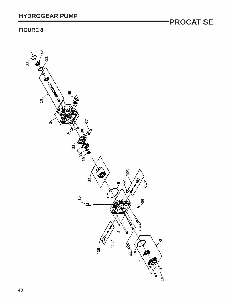
1 70516 ----- HOUSING KIT 12 72011 4164841-001 END CAP KIT 13 50641 ----- STRAIGHT HEADLESS PIN 24 50969 2721615-01 FLANGE BOLT M8-1.25 X 60 45 52629 4164841-002 HOUSING O-RING 16 71261 4168656-01 CHARGE PUMP KIT 17 51346 4168656-02 STD GEROTOR ASSEMBLY 18 51016 4168656-03 O-RING 110 53814 64123-47 BLT-HEX 5/16-18X1-1/4 215 2513030 4157242-019 BYPASS VALVE KIT (BLANK) 118 70522 4137278-05 PUMP SHAFT KIT 120 51161 ----- LIP SEAL 17 x 40 x 12 121 50951 ----- SPACER 122 50329 ----- RETAINING RING 125 71971 4164841-003 CYLINDER BLOCK KIT 129 2003014 ----- BLOCK SPRING 130 2003017 ----- BLOCK THRUST WASHER 132 2003087 188059-11 SWASH PLATE 134 53502 4164841-004 BALL THRUST BEARING 137 2003005 188059-15 ARM-TRUNION 138 2000015 2721615-13 SLOT GUIDE 142A 70742 4168656-04 SHOCK VALVE KIT (.024") 142B 70743 4121354 SHOCK VALVE KIT (.031") 144 70402 4137278-07 CHARGE RELIEF VALVE KIT 149 2513043 2721615-17 TRUNNION SEAL/RETAIN KIT 156 9005110-4400 ----- STRAIGHT THREAD PLUG 157 9005110-5600 4157242-025 PLUG-9/16-20 STEEL 1100 70525 2721615-18 OVERHAUL SEAL KIT 1
ITEM HYDROGEAR PART NO. SCHILLER PART NO. DESCRIPTION QTY

42
PROCAT SEFIGURE 9
AIR COOLED WIRE HARNESS
SWITCH
RW
BR
BR
Y
14 GA.
GROUND
BB
MODULEDELAY
BB
E
RW A
CD
BG
YF
BR
Y
GY
B
RW
B
BR
Y
BLADES &TRACTION
RELAY
NO 87
86
87A30
B
85
NC B
BB
NO
DELAYRELAY
87A
NO 87
86
3087
NC 85
WW
BO
B
STARTERRELAY
86
87AN
C30
85 BB
Y
14 GA
.
OBPOOPDB
WB
BRY
YBRWGYBR
YELLOW W/ BLACK STRIPERED W/ WHITE STRIPEGREEN W/ YELLOW STRIPE
BROWN W/ YELLOW STRIPE
ORANGE W/ BLACK STRIPEPURPLE W/ ORANGE STRIPEORANGE W/ PURPLE STRIPEDARK BLUE
YELLOW
BROWN
Y
BLACKGREENRED
BGR
WHITE W/ BLACK STRIPE
WIRE COLORS
PURPLEORANGE
WHITE
PO
W
ELECTRIC
DB
ENGINE
CLUTCH
B
P
G WY
B
R
STARTER
14 GA
.
14 GA
.
YB
BR
BR
BRAKE
KEY
O
OG
Y
SWITCHSEAT O
RP
R
AUXILIARYELECTRICAL CONNECTION
P
SWITCH
14 GA
.
NC
OP
BR
WW
NO
NOW
B
WB
B
WB
TRACTIONCONTROL
14 GA
.
14 GA
.
BP
OB
OP
WB
O
NO
GO
HOURMETER
CONTROL
B
PO
OB
TRACTION
NO
NC
B14 G
A.
RY
14 GA
.W
DBP
OB
OB
O
O
OO
B
B
ADAPTER12V
OD
BO
SWITCHCLUTCH
TO SOLENOID (3)
172
FUSES
TO SOLENOID (2)
(RED) 1821
18
13 12
RELAY SCHEMATIC
87A NC30
8587 NO
86
9
9
9
10
4
5
8
14
14
15
11
NC
REL
AY
10-2
0 VD
C
NO
S2 T
YPIC
AL
SWIT
CH
BLA
DE
OPT
ION
AL
BA
CE
DF
POSI
TIIO
N),
OR
FO
R A
PPR
OX.
1/2
SEC
ON
D A
FTER
S1
IS O
PEN
ED.
(BLA
DE
DIS
ENG
AG
ED) O
R W
HEN
S1
IS C
LOSE
D (O
PER
ATO
R IN
R
ELAY
IS E
NER
GIZ
ED (E
NG
INE
OPE
RAT
ES) W
HEN
S2
IS C
LOSE
D
DEL
AY M
OD
ULE
OPE
RAT
ION
& S
CH
EMAT
IC
MA
GN
ETO
IGN
ITIO
NS1
TYP
ICA
LO
PER
ATO
RPR
ESEN
CE
SWIT
CH
(BLACK)
(RED)7
3
(GROUND)ENGINE BLOCK
BATTERY
SOLENOID
18
BATTERY
16
193 4
1 2
TO SOLENOID (4)
6
SOLENOID 20
TO ENGINE BLOCK(GROUND)

43
PROCAT SE
ITEM PART NO. DESCRIPTION QTY ITEM PART NO. DESCRIPTION QTY
1 4165575 HARNESS-WIRING MAIN 12 148082-20 FUSE-20 AMP 23 108061-13 CABLE-BATTERY 36 BLACK 14 4124009 SWITCH-SEAT, NO 15 4143068 JUMPER-SEAT SWITCH 16 4165120 METER-HOUR 17 2722227-02 CABLE-BATT CONDUIT 36" 1
2722227-01 CABLE-BATT CONDUIT 28"(INCLUDES ITEMS 18)
8 128010 KEY-SWITCH 19 2722325 RELAY-40AMP SEALED 310 2188154 MODULE-DELAY 111 2721505 SWITCH-PTO 112 4165689 CLUTCH-ELECTRIC 1
(INCLUDES 2720949 WIRE ASSY)
13 2720949 ASSY-CLUTCH WIRE 114 108208 SWITCH-DBL POLE 215 2188156 SWITCH-NONO DBL POLE 116 112386 BOOT-BAT TERM POS 117 4166663 HARNESS-JUMPER 1
(USED ON 942520J ONLY)
2188224 HARNESS-JUMPER 1(USED ON 942522J ONLY)
4164496 HARNESS-JUMPER 1(USED ON 942523J ONLY)
18 2308095 COVER-TERMINAL 219 38665 SOLENOID 1
(USED ON 942522J ONLY)
20 2188225 WIRE-GROUND 1(USED ON KAWASAKI ONLY)
21 108061-04 CABLE-BATTERY 20 RED 1(USED ON 942522J ONLY)
ITEMS 22 & 23 USED ON 61" MODELS 22 4165923 HARNESS-SOFT START 123 4169459 CONTROL-SOFT START 1
FIGURE 9
AIR COOLED WIRE HARNESS

44
PROCAT SEFIGURE 10
SEAT ASSEMBLY
12
1
27
6
4
9
11
13
171514
16
18
19
BRACKET ON
3
ENGINE DECKWELDMENT
8
10

45
PROCAT SE
ITEM PART NO. DESCRIPTION QTY ITEM PART NO. DESCRIPTION QTY
FIGURE 10
SEAT ASSEMBLY
1 4168938 SEAT ASSEMBLY 1(INCLUDES ITEMS 2-4, 6-8, 11-12)
2 4167063-02 COVER-BACK, VINYL 13 4167063-03 COVER-BOTTOM, VINYL 14 4167063-04 KNOB-ARM ADJUSTMENT 25* 4165316-03 KIT-ARM RH & LH 1
(INCLUDES ITEMS 4 ,6 - 8)
6 4165316-02 PAD-ARM SINGLE 27 4165316-05 ARM KIT-LH 1
(INCLUDES ITEMS 4 ,6)
8 4165316-04 ARM KIT-RH 1(INCLUDES ITEMS 4 ,6)
9 4124009 SWITCH-SEAT NO 110 2720975-07 SPACER 211 4167062-02 TRACKSET-SEAT 112 4143068 JUMPER-SEAT SWITCH 113 4167770.7 PLATE-SEAT 114 48228A CABLE CLIP-INSULATED 215 64152-23 SCREW 1/4-20X3/8 216 2720975-09 SPACER 217 64141-6 NUT-WLF 5/16-18 418 64144-30 SNAP RING 219 33138-09 PIN-CLEVIS 2
* NOT ILLUSTRATED

46
PROCAT SEFIGURE 11
FOLDING ROPS
13
4
3
5
2
7
1
1
13
2
4
75
109
8
12
11
6
12
8
1

47
PROCAT SE
ITEM PART NO. DESCRIPTION QTY ITEM PART NO. DESCRIPTION QTY
FIGURE 11
FOLDING ROPS
1 4168257 S-ROPS W/ LABELS 1 (INCLUDES ITEMS 2-13)
2 64123-31 BOLT-1/2-13 X 3 23 64151-7 LOCKNUT- 1/2-13 24 4162880 LANYARD-NYLON 25 64262-011 BLT-FLG HD 3/8-16X1 86 4160347 LABEL-WARNING ROPS 17 64268-03 NUT-FL NYLN LOCK 3/8-16 88 64168-1 PIN-COTTER 29 4160343 BUMPER RUBBER 210 4160344 PLUG 211 4160348 WASHER-FORMED 212 4162878 WASHER-RUBBER 213 4162879 PIN-HITCH 1/2 2

48
PROCAT SEFIGURE 12
STEERING/DECK LIFT
3736
3
4
32
30
40
14
2618
28
34
41
2922
17
23
25
4839
15
43
5
9
15
1310
12
27
45
51
19
7
46
36
15
15
42
24 15
11
47
472
9
844
6
21
49 50
31
20
1
16
3338
35

49
PROCAT SE
ITEM PART NO. DESCRIPTION QTY ITEM PART NO. DESCRIPTION QTY
FIGURE 12
STEERING/DECK LIFT
1 4167906 S ENGINE DECK W/LABS 12 4163746 SPRING 23 4165962 ZERK-90 DEGREE 24 64123-50 BLT-HEX 3/8-16X1 15 4165426.7 LEVER-TRACTION CNTRL 26 4166920.7 BRKT-TRACTION LEVER 27 4169529 BAR-TRACTION CONTROL 28 4165432 GRIP-HANDLE 29 2188145 BEARING-.SELF ALIGN 410 64123-15 BOLT-3/8-16X3/4 HEX 811 64141-4 NUT-WLF 3/8-16 812 4167143 WLDMT-MTN CONTRL LH 1 * 4167144 WLDMT-MTN CONTRL RH 1
13 64123-87 BLT-HEX 3/8-16X1-3/4 2 14 64123-16 BLT-HEX 3/8-16X1-1/4 1215 64229-03 NUT-NYLON LOCK 3/8-16 2016 64262-011 BLT-FLG HD 3/8-16 X 1 617 64123-67 BLT-HEX 3/8-16X2 118 64163-43 WSHR.443/.454X1X11GA 119 4165474 SPACER 220 4165390.7 WLDMT-CRADLE 121 64168-2 COTTER-HAIRPIN.08X1.19 222 4167153.7 WLDMT-DECK LIFT LEVER 123 4162904.7 WLDMT-LVR STOP LATCH 124 4165384.7 BRKT-INNER DECK LIFT 125 4165385.7 BRKT-OUTER DECK LIFT 126 4165389.7 BRACKET-LIFT LINK 227 4162999 SPACER 228 4165656 ASSY, PIN & LANYARD 129 64188-76 PIN-CLEVIS 1/2X1-3/8 130 64018-38 BOLT-CRG 3/8-16 X 2-1/4 1
31 85010N ZERK, 1/4-28 STR SELF TH 1132 64221-04 E-RING .875 133 64175-05 NUT-PUSH 1/2 134 64188-36 PIN, CLEVIS 7/16X1-1/4 235 4167151 GRIP 136 2183071-03 SPACER-15.88X10.32X24 237 64268-02 NUT-FL NY LOCK 5/16-18 138 4167159.7 ARM-LATCH 1 39 4167138 SPRING-TORSION 140 64163-65 WSHR .890X1.375X18GA 641 4165654 LBL-ZT200 HT CUT OUTER 142 4165655 LBL-ZT200 HT CUT INNER 143 64268-03 NUT-FL NYLON LOCK 3/8-16 244 4163692 CAP-END 245 64018-7 BLT-CRG 3/8-16X1-1/4 446 4163446 KNOB 247 64163-55 WSHR .328X.75X14 GA 448 64123-47 BLT-HEX 5/16-18X1-1/4 249 64262-011 BLT-FLG HD 3/8-16 X 1 450 4167139.7 PLATE-FOOT PLATE MNTNG 251 64229-03 NUT-NYLON LOCK 3/8-16 4
*NOT ILLUSTRATED
50
PROCAT SEFIGURE 13
CRADLE ASSEMBLY
43
39
38
40
30
16
2
28
2
132123
27
12
14
15
KICKPLATE
TO
29 27
2022
22
37
7
1
4
25
5
11
30
16
28
13
21
23
25
25
3
28
17
28
2825
25
3
109
17
19
5
3426
33
3536
910
32
30
8
31
24
42
641

51
PROCAT SE
ITEM PART NO. DESCRIPTION QTY ITEM PART NO. DESCRIPTION QTY
FIGURE 13
CRADLE ASSEMBLY
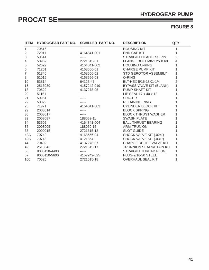
1 4165610 LABEL-WARNING 12 2182356.7 BRACKET-SHAFT HANGER 43 2188127 CHAIN-6.35 (.250) 5 LINKS 44 4165647 MAT-FOOT PLATE LOWER 15 4166266 MAT-FOOT PLATE UPPER 26 4167139.7 PLATE-FOOTPLATE MNTG 27 4165657 LABEL-PROCAT 18 4166267 S-FOOT PLATE (BOBCAT) 1
(INCLUDES ITEMS 4-7)
9 64163-65 WASHER-.890X1.375X18GA 810 64221-04 E-RING.875 411 4165379.7 WLDMT-DECK LIFT, FRONT 112 4165427.7 WLDMT-DECK LIFT, REAR 113 2722630 CLIP-DECK HEIGHT ADJ 414 4165675 SPRING-DECK LIFT 215 4165390.7 WLDMT-CRADLE 116 64268-03 NUT-FL NYLN LCK 3/8-16 1517 4167826 ROD-DECK LIFT 218 * 4111842.7 BRKT-SPRING ANCHOR LH 119 4165556 MAT-FOOT LIFT 120 4113682 ROD-SPRING MOUNT 221 64141-2 NUT-WLF 1/4-20 422 64141-4 NUT-WLF 3/8-16 423 64197-020 BLT-TDFM 1/4-20X1-1/2 424 64268-02 NUT-FL NYLON LOCK 5/16-18 325 64123-281 BLT-HEX 1/2-13X2 FL THRD 1026 4165596.7 BRKT-FOOT, LIFT LEVER 127 64262-011 BLT-FLG HD 3/8-16 X 1 1528 64141-13 NUT WLF 1/2-13 1629 85010N ZERK, 1/4-28 STR SLFTHRD 130 85051 ZERK-1/8 PIPE 631 64229-03 NUT-NYLON LOCK 3/8-16 132 64018-3 BLT-CRG 3/8-16X1 233 4165593.7 WLDMT-FOOT PEDAL 134 64123-100 BLT-HEX 3/8-16X2-1/4 135 64123-67 BLT-HEX 3/8-16X2 236 64001-6 NUT-HEX JAM 3/8-16 237 64229-05 NUT-NYLON LOCK 3/8 238 64018-2 BLT-CRG 1/4-20X3/4 239 64268-01 NUT-FL NYLON LOCK 1/4-20 240 4160281 DOCUMENT TUBE 141 4163802-01 SPACER-1.0 X .516 X .75 242 4164210 BUMPER-RUBBER 343 38061A CAP-DOCUMENT TUBE 1
*NOT ILLUSTRATED

52
PROCAT SEFIGURE 14
CRADLE & CASTER ASSEMBLY
11
64
518
15
1
151022
14
19
13
8
20
8
13
21
12
23
3
9
7
7
29
17
17
17
17
16
16
53
PROCAT SE
ITEM PART NO. DESCRIPTION QTY ITEM PART NO. DESCRIPTION QTY
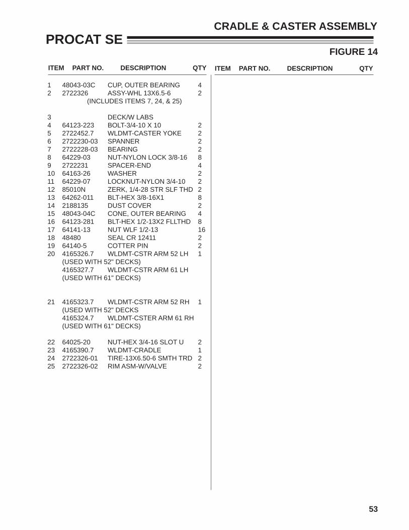
FIGURE 14
CRADLE & CASTER ASSEMBLY
1 48043-03C CUP, OUTER BEARING 42 2722326 ASSY-WHL 13X6.5-6 2 (INCLUDES ITEMS 7, 24, & 25)
3 DECK/W LABS 4 64123-223 BOLT-3/4-10 X 10 25 2722452.7 WLDMT-CASTER YOKE 26 2722230-03 SPANNER 27 2722228-03 BEARING 28 64229-03 NUT-NYLON LOCK 3/8-16 89 2722231 SPACER-END 410 64163-26 WASHER 211 64229-07 LOCKNUT-NYLON 3/4-10 212 85010N ZERK, 1/4-28 STR SLF THD 213 64262-011 BLT-HEX 3/8-16X1 814 2188135 DUST COVER 215 48043-04C CONE, OUTER BEARING 416 64123-281 BLT-HEX 1/2-13X2 FLLTHD 817 64141-13 NUT WLF 1/2-13 16 18 48480 SEAL CR 12411 219 64140-5 COTTER PIN 220 4165326.7 WLDMT-CSTR ARM 52 LH 1 (USED WITH 52" DECKS) 4165327.7 WLDMT-CSTR ARM 61 LH (USED WITH 61" DECKS)
21 4165323.7 WLDMT-CSTR ARM 52 RH 1 (USED WITH 52" DECKS 4165324.7 WLDMT-CSTER ARM 61 RH (USED WITH 61" DECKS)
22 64025-20 NUT-HEX 3/4-16 SLOT U 223 4165390.7 WLDMT-CRADLE 124 2722326-01 TIRE-13X6.50-6 SMTH TRD 225 2722326-02 RIM ASM-W/VALVE 2

54
PROCAT SEFIGURE 15
52" SIDE DISCHARGE
83
4246
76
6768
4948
70 FT-LBSTORQUE TO
68
50
75
46
15
17
23
29
30
432755
4133
6 51
5254
47
57
4021
2211
14
58
61575960
66 62
19
62
18
19 6970
3
4
3538
45
34
3332 10
28
9 13
56
8
26
63
913
7
7
3712
1670
83
21
39
83
70
20
27
453
3535
7
5
367
65
76
23
31
46
46
83
74
78
79
77
8180
36
79
82
73
71
64
72
44

55
PROCAT SE
ITEM PART NO. DESCRIPTION QTY ITEM PART NO. DESCRIPTION QTY
FIGURE 15
52" SIDE DISCHARGE
1 4166117 S-DECK W/ LABELS 52" ZT2 12 4165608.7 COVER-BELT RH 13 4165609.7 COVER-BELT LH 14 64268-01 NUT-FL NYLON LOCK 1/4-20 35 4165244 CHUTE-RUBBER ASSY 16 548138 BRG NDL.88 1.12 1.00 17 64229-03 NUT-NYLON LOCK 3/8-16 348 64123-173 BLT-HEX 3/8-16X4-1/2 39 2721512 ROLLER-5X2.75 CENTERED 610 64123-68 BLT-HEX 5/16-18X1 211 4165646 PULLEY-5.25 DEEP GRVE 312 112111-02 BLADE 18.00 OFFST HLFT 313 2720685 SPACER-ROLLER 614 64262-012 BLT-FLG HD 3/8-16 X 1-1/4 1815 4168888.7 WLDMT-IDLER ARM 116 64018-11 BLT-CRG 1/2-13X3LG 317 4168884.7 GUIDE, BELT 118 4165953 PULLEY-IDLER, 6.0 119 4162578-02 SPACER-2.0 X .515 X1.07 220 4168805.2 BAFFLE-DISCHARGE 121 64209-03 SPRING WASHER.67 ID 622 64164-12 KEY-1/4X1 SQ 323 128169 PULLEY IDLER 5.50 224 4165023 ASSY-CTTERDECK SPNDL 325 4168886 ASSY-IDLER ARM 48-52 1
(INCLUDES ITEMS 6, 15, 33, 41,51 & 55)
26 90-0828 S/B BOLT 1/2-13X3 1/2 NC 127 64270-02 BLT-HEX M10-1.5x30 ISO 128 4133155.7 WLDMT-PUSH ARM ZT2 229 64163-67 WSHR-.516X1X12GA 130 64018-45 BLT-CRG, 1/2-13 X 2-1/4 131 64163-74 WSHR-.516X2.00X.25 PLT 132 2186125 WLDMT-LOCK PUSHBAR 233 85010N ZERK 1/4-28 STR SLF THRD 534 64123-152 BLT-HEX 5/8-11X5 235 64123-50 BLT-HEX 3/8-16X1 536 64229-02 NUT-NYLON LOCK 5/16-18 337 4118314 SPACER-BLADE 16MM 338 64229-06 NUT-NYLON LOCK 5/8-11 239 64123-187 BLT-HEX 5/8-18 X 3 3/4 340 64123-208 BLT-HEX 5/8-18X1-1/2 341 4128004 BEARING-BALL 10 X 26 X 8 142 4168516.7 BAFFLE-FRONT,RH 52IN 143 4128002 CAP-26 X 7 END 144 41684933 SPRING-EXTENSION 145 64163-93 WSHR-.635 X 1.12 X.062 446 64018-2 BLT-CRG 1/4-20X3/4 747 64018-7 BLT-CRG 3/8-16X1-1/4 3
48 64229-01 NUT-NYLON LOCK 1/4-20 449 4165966.7 BAFFLE-FRONT,CENTER 150 4165965.7 BAFFLE-FRONT,LH 52IN 151 521438 GREASE SEAL 152 4163014 SPACER 153 64123-16 BLT-HEX 3/8-16X1-1/4 254 4163155 INNER RING 155 64144-40 SNAP RING-2NTERNL 156 64018-23 BLT-CRG 3/8-16X3/4 SHRT 257 38348-01 BEARING-SPINDLE SEALED 658 4164948 HOUSING-SPINDLE 6 HOLE 359 64144-38 RING-SNAP 360 38315 NUT-SPINDLE 361 2183070-02 SHAFT-SPINDLE 362 64268-05 NUT-FL NYLON LOCK 1/2-13 263 64018-30 BLT-CRG 3/8-16 X 4-1/2 364 64123-114 BLT-1/4-20X1 765 4165252.7 HINGE-CHUTE_RUBBER 166 4168509.7 WLDMT-IDLER PIN 167 4168515.2 BRKT-BAFFLE MOUNTING 168 4168514.2 BRKT-BAFFLE MNTG 269 64123-171 BLT-HEX 3/8-16X3-1/2 270 64141-4 NUT-WLF 3/8-16 471 4166478.2 EXTENSION-52" RH 172 4166479.2 EXTENSION-52" LH 173 64141-2 NUT-WLF 1/4-20 774 64163-64 WSHR 1.015X1.500X14GA 375 64123-15 BLT-HEX 3/8-16X3/4 376 64268-03 NUT-FL NYLON LOCK 3/8-16 677 64151-37 NUT-HEX,1/2-13NYLON JAM 178 64018-34 BLT-CRG 5/16-18 X 1-1/2 179 64141-6 NUT-WLF 5/16-18 280 4169597 EYE BOLT 5/16-18 X 1.5 181 4169461.2 WLDMT-IDLR MNTNG 182 64163-55 WSHR-.328X.75X14 GA 183 38524 KNOB-4 PRONG 3/8-16 2
* NOT ILLUSTRATED

56
PROCAT SEFIGURE 16
61" SIDE DISCHARGE
33
79
62
76 76
31
56 7
2
77
65
20
83
5
64
46
714
742
46
72
74
46
497
48
5046
7221
3712
39
70
68
13
79
7
69671670
63
376
60
59
57
61
23
19
58
1457
6
11
6662
54
41
51
55
33
73
22
27
21
43
40
15
52
29
30
23
17
44
47
69
1
24
35
7575
8
139
7
48
53
4
78
8025
78
82
82
36
3845
34
33 32 10
28
77
8081
74
75
75
74
36
18
19
26

57
PROCAT SE
ITEM PART NO. DESCRIPTION QTY ITEM PART NO. DESCRIPTION QTY
FIGURE 16
61" SIDE DISCHARGE
1 4166118 S-DECK W/ LABELS 61" 12 4165456.7 BELT COVER-RH 13 4165455.7 BELT COVER-LH 14 64268-01 NUT-FL NYLON LOCK 1/4-20 35 4165244 CHUTE-RUBBER ASSY 16 64163-68 WSHR-1.015X1.5X9GA 67 64229-03 NUT-NYLON LOCK 3/8-16 398 64123-173 BLT-HEX 3/8-16X4-1/2 39 2721512 ROLLER-5X2.75 CENTERED 710 64123-68 BLT-HEX 5/16-18X1 211 2308140 PULLEY-ENGINE 312 112111-03 BLADE 21.00 OFFST HLFT 313 2720685 SPACER-ROLLER 714 64262-012 BLT-FLG HD 3/8-16 X 1-1/4 1815 4168888.7 WLDMT-IDLER ARM 116 64018-11 BLT-CRG 1/2-13X3LG 117 4168884.7 GUIDE, BELT 118 4165953 PULLEY-IDLER, 6.0 119 4152578-02 SPACER-2.0 X .516 X 1.07 220 4168085.2 BAFFLE-DISCHARGE 121 64209-03 SPRING WASHER.67 ID 622 64164-12 KEY-1/4X1 SQ 323 128169 PULLEY IDLER 5.50 224 4165023 ASSY-CTTERDCK SPINDLE 325 4168886 ASSY-IDLER ARM 1(INCLUDES ITEMS 15, 33, 41, 51, 55, & 73)
26 90-0828 S/B BOLT 1/2-13X3 1/2 NC 127 64270-02 BLT-HX M10-1.5x30 ISO 128 4133155.7 WLDMT-PUSH ARM ZT2 229 64151-37 NUT-HEX,1/2-13NYLON JAM 130 64018-45 BLT-CRG, 1/2-13 X 2-1/4 131 64163-74 WSHR-.516IX2.00OX.250 132 2186125 WLDMT-LOCK PUSHBAR 233 85010N ZERK 1/4-28 STR SLF THRD 534 64123-152 BLT-HEX 5/8-11X5 235 64123-50 BLT-HEX 3/8-16X1 936 64229-02 NUT-NYLON LOCK 5/16-18 337 4118314 SPACER-BLADE 16MM 338 64229-06 NUT-NYLON LOCK 5/8-11 239 64123-187 BLT-HEX 5/8-18 X 3 3/4 340 64123-208 BLT-HEX 5/8-18X1-1/2 341 4128004 BEARING-BALL 10 X 26 X 8 142 4168643.7 BAFFLE-FRONT,RH 61IN 143 4128002 CAP-26 X 7 END 144 4168493 SPRING-EXTENSION 145 64163-93 WSHR-.635 X 1.12 X.062 446 64018-2 BLT-CRG 1/4-20X3/4 747 64018-7 BLT-CRG 3/8-16X1-1/4 3
48 64229-01 NUT-NYLON LOCK 1/4-20 749 4168642.7 BAFFLE-FRONT,CNTR 61IN 150 4165968.7 BAFFLE-FRONT,LH 61IN 151 521438 GREASE SEAL 152 4163014 SPACER 153 64163-55 WSHR .328X.75X14 GA 154 4163155 INNER RING 155 64144-40 SNAP RING-26MM INTENA 156 64018-23 BLT-CRG 3/8-16X3/4 257 38348-01 BEARING-SPINDLE SEALD 658 4164948 HOUSING-SPINDLE 6 HOLE 359 64144-38 RING-SNAP 360 38315 NUT-SPINDLE 361 2183070-02 SHAFT-SPINDLE 362 64268-05 NUT-FL NYLON LOCK 1/2-13 263 64018-30 BLT-CRG 3/8-16 X 4-1/2 464 64123-16 BLT-HEX 3/8-16X1-1/4 265 4165252.7 HINGE-RUBBER CHUTE 166 4168509.7 WLDMT-IDLER PIN 167 4166480.2 EXTENSION-61"RH 168 4166481.2 EXTENSION-61"LH 169 64141-2 NUT-WLF 1/4-20 770 64123-114 BLT-HEX 1/4-20X1 771 4168487.2 BRKT-BAFFLE MNYNG, RH 172 4168523.2 BRKT-BAFFLE MNTG 273 548138 BRG NDL.88 1.12 1 174 64123-171 BLT-HEX 3/8-16X3-1/2 275 64141-4 NUT-WLF 3/8-16 476 64123-15 BLT-HEX 3/8-16X3/4 377 4169597 EYE BOLT-5/16-18 X 1-1/2 178 64163-67 WSHR-5/16 X 1X 12 GA 279 64018-34 BLT-CRG 5/16-18 x 1-1/2 180 64141-6 NUT-WLF 5/16-18 281 4169671 S-ASSY, IDLER SPR MNT 182 38524 KNOB-4 PRONG 3/8-16 283 64268-03 NUT-FL NYLON LOCK 3/8-16 2
58
PROCAT SEFIGURE 17
BELTS-CUTTERDECK
1

59
PROCAT SE
ITEM PART NO. DESCRIPTION QTY ITEM PART NO. DESCRIPTION QTY
FIGURE 17
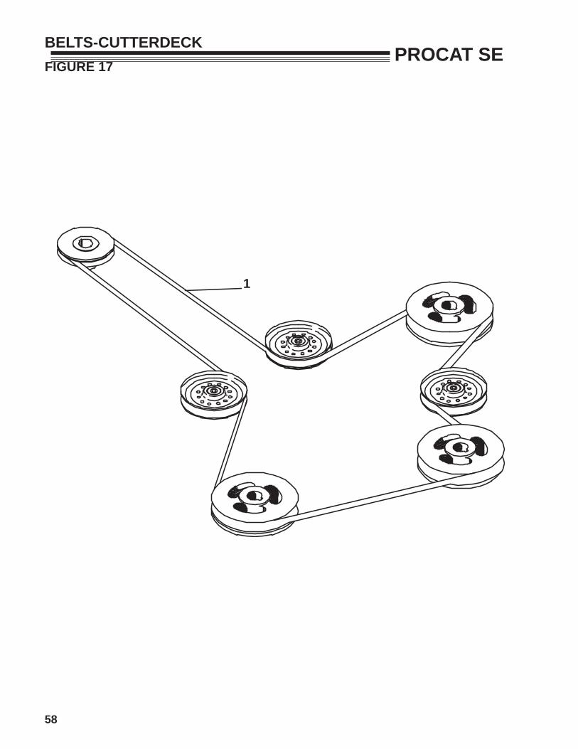
BELTS-CUTTERDECK
1 4169640 BELT-CUTTERDECK 52" 14169463 BELT-CUTTERDECK 61"

60
PROCAT SEFIGURE 18
DECALS-POWER UNIT
DOCUMENT3TUBE
ENGINE DECK8 BACK OF
117
209
14
1
17
13
18
12
10
6
15LOCATED BEHIND SEAT ON OIL COOLER
UNDER SEAT4
16
LOCATED UNDER FOOTPLATE
5
2
19
61
PROCAT SE
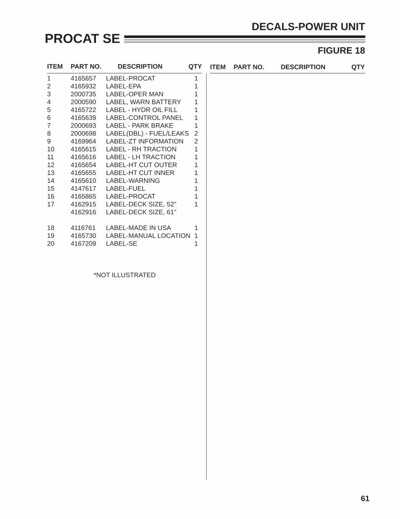
ITEM PART NO. DESCRIPTION QTY ITEM PART NO. DESCRIPTION QTY1 4165657 LABEL-PROCAT 12 4165932 LABEL-EPA 13 2000735 LABEL-OPER MAN 14 2000590 LABEL, WARN BATTERY 15 4165722 LABEL - HYDR OIL FILL 16 4165639 LABEL-CONTROL PANEL 17 2000693 LABEL - PARK BRAKE 18 2000698 LABEL(DBL) - FUEL/LEAKS 29 4169964 LABEL-ZT INFORMATION 210 4165615 LABEL - RH TRACTION 111 4165616 LABEL - LH TRACTION 112 4165654 LABEL-HT CUT OUTER 113 4165655 LABEL-HT CUT INNER 114 4165610 LABEL-WARNING 115 4147617 LABEL-FUEL 116 4165865 LABEL-PROCAT 117 4162915 LABEL-DECK SIZE, 52" 1
4162916 LABEL-DECK SIZE, 61"
18 4116761 LABEL-MADE IN USA 119 4165730 LABEL-MANUAL LOCATION 120 4167209 LABEL-SE 1
*NOT ILLUSTRATED
FIGURE 18
DECALS-POWER UNIT

62
PROCAT SE
1
FIGURE 22
DECALS-CUTTERDECKS

63
PROCAT SE
ITEM PART NO. DESCRIPTION QTY ITEM PART NO. DESCRIPTION QTY
FIGURE 22
DECALS-CUTTERDECKS
1 4164269 LABEL-WARNING BLADES 1 (ON SIDE DISCHARGE MODELS)
2 2000577 LABEL-WARNING 2

SCHILLER GROUNDS CARE, INC.ONE BOB-CAT LANEP.O. BOX 469JOHNSON CREEK, WI 53038920-699-2000www.schillergc.com ©Schiller Grounds Care, Inc. 2010