bdf solutions – led leuchten lemgo - test report iec ......led street light for outdoor and indoor...
TRANSCRIPT

Page 1 of 45
TRF No. IEC60598_2_3K
TEST REPORTIEC 60598-2-3Luminaires
Part 2: Particular requirementsSection 3: Luminaires for road and street lighting
Report Number. ............................. : 68.140.17.146.02A
Date of issue ................................. : 2018-12-17
Total number of pages ................... 45 (not including attachments)
Name of Testing Laboratorypreparing the Report ..................... :
TÜV SÜD Certification and Testing (China) Co., Ltd. ShenzhenBranch
Applicant’s name .......................... : SWEETLIGHT LCE, Bianca Dietz
Address ......................................... : Münchner Str. 6, 94563 Otzing, GERMANY
Test specification:Standard ........................................ : IEC 60598-2-3:2002/AMD1:2011 used in conjunction with
IEC 60598-1:2014
Test procedure .............................. : CE-LVD
Non-standard test method ............ : N/A
Test Report Form No. ................... : IEC60598_2_3K
Test Report Form(s) Originator .... : Intertek Semko AB
Master TRF .................................... : 2016-09
Copyright © 2016 IEC System of Conformity Assessment Schemes for Electrotechnical Equipmentand Components (IECEE System). All rights reserved.This publication may be reproduced in whole or in part for non-commercial purposes as long as theIECEE is acknowledged as copyright owner and source of the material. IECEE takes no responsibility forand will not assume liability for damages resulting from the reader's interpretation of the reproducedmaterial due to its placement and context.General disclaimer:The test results presented in this report relate only to the object tested.This report shall not be reproduced, except in full, without the written approval of the Issuing CB TestingLaboratory. The authenticity of this Test Report and its contents can be verified by contacting the NCB,responsible for this Test Report.

Page 2 of 45 Report No.: 68.140.17.146.02A
TRF No. IEC60598_2_3K
Test item description ...................... : LED Street Light
Trade Mark ...................................... :
Manufacturer................................... : Same as applicantModel/Type reference ..................... : SL-SLA30; SL-SLA60;
SL-SLA90; SL-SLA120;SL-SLA150; SL-SLA180;SL-SLA210; SL-SLA240;SL-SLA270; SL-SLA300;SL-SLB40; SL-SLB80;SL-SLB120; SL-SLB160;SL-SLB200; SL-SLB240;SL-SLB280; SL-SLB320
Ratings ............................................ : 220-240VAC; 50/60Hz;30W [SL-SLA30]; 60W [SL-SLA60];90W [SL-SLA90]; 120W [SL-SLA120];150W [SL-SLA150]; 180W [SL-SLA180];210W [SL-SLA210]; 240W [SL-SLA240];270W [SL-SLA270]; 300W [SL-SLA300];40W [SL-SLB40]; 80W [SL-SLB80];120W [SL-SLB120]; 160W [SL-SLB160];200W [SL-SLB200]; 240W [SL-SLB240];280W [SL-SLB280]; 320W [SL-SLB320]


Page 4 of 45 Report No.: 68.140.17.146.02A
TRF No. IEC60598_2_3K
List of Attachments (including a total number of pages in each attachment):
Attachment No.1: EU Group Differences and National differences (2 pages);
Attachment No.2: EN 62031:2008+A1:2013+A2:2015: LED modules for general lighting – Safetyspecifications (5 pages);
Attachment No.3: IEC TR 62778:2014 –blue light hazard to light sources and luminaires (2 pages)
Attachment No.4: Photo documentation (18 pages).
Summary of testing:Tests performed (name of test and testclause):
Testing location:Building 12&13, Zhiheng Wisdomland Business ParkNantou Checkpoint Road 2, Nanshan District 518052Shenzhen CHINA
EN 60598-2-3:2003+A1:2011EN 60598-1:2015EN 62493:2015
The LED modules in products were found tocomply with the requirements of EN62031:2008+A1:2013+A2:2015.
The submitted samples were LED-light-sourcetechnology, they were found to comply with therequirement of EN 62493:2015 without test.
The submitted samples with XP-G3 LED wereclassified as RG2 and with other LED typeswere classified as RG1 according to IEC TR62778:2014.
The submitted samples were found to complywith above test specification.
Summary of compliance with National Differences:– European Group difference and national difference
The product fulfils the requirements of below standards:Ø EN 60598-2-3:2003+A1:2011Ø EN 60598-1:2015Ø EN 62493:2015

Page 5 of 45 Report No.: 68.140.17.146.02A
TRF No. IEC60598_2_3K
Copy of marking plate:The artwork below may be only a draft. The use of certification marks on a product must beauthorized by the respective NCBs that own these marks.Representative label
Location: sticking on metal enclosure.
Remark:· The labels of other models are same as above label, except model number and rated power.
· (for all models) Label for Caution, risk of electric shock; Location: silk-screen on thecover of LED module (height at least 15mm)
· for models which used XP-G3 LED. Do not stare at the operating light source; Location:silk-screen on the cover of LED module (height at least 5mm)
· Height of CE marking at least 5mm, height of WEEE mark at least 7mm, height of other marks atleast 5mm, height of letters and numerals at least 2mm.
· According to the EU decision 768/2008/EC, the name and address of manufacturer (an EU-based importer or authorized representative if the manufacturer is not based in EU) shall beaffixed on the product or, where that is not possible, on its packaging or in a documentaccompanying the product before the product is placed on EU market.

Page 6 of 45 Report No.: 68.140.17.146.02A
TRF No. IEC60598_2_3K
Test item particulars:
Classification of installation and use .....................: Fixed and suitable for indoor and outdoor use
Supply Connection.................................................: Terminal (terminal block)
Protection class ....................................................: Class I
Degree of protection ..............................................: IP67
ta.............................................................................: 50°C
Possible test case verdicts:- test case does not apply to the test object .......... : N/A
- test object does meet the requirement ................ : P (Pass)
- test object does not meet the requirement .......... : F (Fail)
Testing:Date of receipt of test item ..................................... : 2018-12-07
Date (s) of performance of tests ............................ : 2018-12-07 to 2018-12-17
General remarks:
"(See Enclosure #)" refers to additional information appended to the report."(See appended table)" refers to a table appended to the report.
Throughout this report a comma / point is used as the decimal separator.The manufacturer/ Importer has to ensure the appliance placing on the EU market conforms to theapplicable EU directives which provide the affixing of the CE marking, such as LVD, EMC, RoHS, ErP,and so on.
Manufacturer’s Declaration per sub-clause 4.2.5 of IECEE 02:
The application for obtaining a CB Test Certificateincludes more than one factory location and adeclaration from the Manufacturer stating that thesample(s) submitted for evaluation is (are)representative of the products from each factory hasbeen provided .......................................................... :
Yes Not applicable
When differences exist; they shall be identified in the General product information section.
Name and address of factory (ies) ........................ : Same as applicant

Page 7 of 45 Report No.: 68.140.17.146.02A
TRF No. IEC60598_2_3K
General product information:LED street light for outdoor and indoor use.For all models, maximum mounting height is 12m.Details information are listed as follows:
Model No. Ratedpower (W)
Mountingheight (m)
LED driver LEDmodulequantity
(pcs)
Weight(kg)
Size (L x W x H)(mm)
SL-SLA series
SL-SLA30 30 6-12 1 type D or 1 type E 1 6,13 463 x 345 x 116
SL-SLA60 60 6-12 1 type D or 1 type E 2 7,09 523 x 345 x 116
SL-SLA90 90 6-12 1 type B or 1 type F 3 8,02 583 x 345 x 116
SL-SLA120 120 6-12 1 type B or 1 type F 4 8,71 643 x 345 x 116
SL-SLA150 150 6-12 1 type B 5 9,47 703 x 345 x 116
SL-SLA180 180 6-12 1 type D + 1 type B or1 type E + 1 type F
6 10,98 763 x 345 x 116
SL-SLA210 210 6-12 1 type D + 1 type B or1 type E + 1 type F
7 11,62 823 x 345 x 116
SL-SLA240 240 6-12 2 x type B or 2 type F 8 12,39 883 x 345 x 116
SL-SLA270 270 6-12 2 x type B 9 13,06 943 x 345 x 116
SL-SLA300 300 6-12 2 x type B 10 13,73 1003 x 345 x116
SL-SLB series
SL-SLB40 40 6-12 1 type A or 1 type E 1 6,13 463 x 345 x 116
SL-SLB80 80 6-12 1 type A or 1 type E 2 7,09 523 x 345 x 116
SL-SLB120 120 6-12 1 type B or 1 type F 3 8,02 583 x 345 x 116
SL-SLB160 160 6-12 1 type B or 1 type F 4 8,71 643 x 345 x 116
SL-SLB200 200 6-12 1 type D + 1 type B or1 type E + 1 type F
5 9,69 703 x 345 x 116
SL-SLB240 240 6-12 1 type D + 1 type B or1 type E + 1 type F
6 10,98 763 x 345 x 116
SL-SLB280 280 6-12 2 type B or 2 type F 7 11,62 823 x 345 x 116
SL-SLB320 320 6-12 2 type B or 2 type F 8 12,39 883 x 345 x 116
Code LED driver model Rated value
Type A XITANIUM 75W 0.70AAOCM 1-10 GL-Y sXt
Input: 120-277VAC; 50/60Hz; 0,7…0,3A;Output: 54-107VDC; 0,1-0,7A; Uout=130VDC; Prated=75W;ta:55°C; tc: 80°C; Built-in
Type B Xitanium 150W 0.35-0.70AGL Prog sXt
Input: 120-277VAC; 50/60Hz; 1,4...0,6A;Output: 125-280VDC; 350-700mA; Uout=300VDC;Prated=150W; tc: 80°C; Built-in

Page 8 of 45 Report No.: 68.140.17.146.02A
TRF No. IEC60598_2_3K
Type D Xitanium 75W 0.35-0.70AGL Prog sXt
Input: 120-277VAC; 50/60Hz; 0,7...0,3A;Output: 54-107VDC; 100-700mA; Uout=160VDC;Prated=75W; tc: 80°C; Built-in
Type E Xitanium Dim 100W 0.7A 1-10V 230V Y
Input: 220-240VAC; 50/60Hz; 0,4…0,56A;Output: 0,7A; 64-143VDC; Uout=220VDC; Prated=100W;ta: 55°C; tc: 80°C; Built-in
Type F Xitanium Dim 150W 0.7A 1-10V 230V Y
Input: 220-240VAC; 50/60Hz; 0,6…0,83A;Output: 0,7A; 96-214VDC; Uout=320VDC; Prated=150W;ta: 55°C; tc: 80°C; Built-in
LED driver:- The insulation between primary to secondary is considered as basic insulation;- The insulation between primary/secondary to housing is considered as basic insulation.Wire preparation for supply cable:
Unless otherwise specified, the models SL-SLA300 and SL-SLB320 were chosen as representativemodels to perform all tests.

Page 9 of 45 Report No.: 68.140.17.146.02A
IEC 60598-2-3
Clause Requirement + Test Result - Remark Verdict
TRF No. IEC60598_2_3K
3.2 (0) GENERAL TEST REQUIREMENTS ¾
3.2 (0.1) Information for luminaire design considered ............ : Yes No ¾
3.2 (0.3) More sections applicable ........................................ : Yes No ¾
3.4 (2) CLASSIFICATION ¾
3.4 (2.2) Type of protection .................................................. : Class I ¾
3.4 (2.3) Degree of protection ............................................... : IP67 ¾
3.4 (2.4) Luminaire suitable for direct mounting on normallyflammable surfaces ................................................ :
Yes No ¾
3.4 (2.5) Luminaire for normal use ....................................... : Yes No ¾
Luminaire for rough service .................................... : Yes No ¾
3.4 (-) Modes of installation of road or street lighting ¾
a) on a pipe Yes No ¾
b) on a mast arm Yes No ¾
c) on a post top Yes No ¾
d) on span or suspension wires Yes No ¾
e) on a wall Yes No ¾
3.5 (3) MARKING ¾
3.5 (3.2) Mandatory markings P
Position of the marking P
Format of symbols/text P
3.5 (3.3) Additional information P
Language of instructions English P
3.5 (3.3.1) Combination luminaires N/A
3.5 (3.3.2) Nominal frequency in Hz 50/60Hz P
3.5 (3.3.3) Operating temperature N/A
3.5 (3.3.4) Symbol or warning notice N/A
3.5 (3.3.5) Wiring diagram N/A
3.5 (3.3.6) Special conditions N/A
3.5 (3.3.7) Metal halide lamp luminaire – warning N/A
3.5 (3.3.8) Limitation for semi-luminaires N/A
3.5 (3.3.9) Power factor and supply current N/A

Page 10 of 45 Report No.: 68.140.17.146.02A
IEC 60598-2-3
Clause Requirement + Test Result - Remark Verdict
TRF No. IEC60598_2_3K
3.5 (3.3.10) Suitability for use indoors P
3.5 (3.3.11) Luminaires with remote control N/A
3.5 (3.3.12) Clip-mounted luminaire – warning N/A
3.5 (3.3.13) Specifications of protective shields N/A
3.5 (3.3.14) Symbol for nature of supply P
3.5 (3.3.15) Rated current of socket outlet N/A
3.5 (3.3.16) Rough service luminaire N/A
3.5 (3.3.17) Mounting instruction for type Y, type Z and some typeX attachments
N/A
3.5 (3.3.18) Non-ordinary luminaires with PVC cable N/A
3.5 (3.3.19) Protective conductor current in instruction ifapplicable
N/A
3.5 (3.3.20) Provided with information if not intended to bemounted within arm’s reach
N/A
3.5 (3.3.21) Non-replaceable and non-user replaceable lightsources information provided
Non-user replaceable lightsources
P
Cautionary symbol P
3.5 (3.3.22) Controllable luminaires, classification of insulationprovided
N/A
3.5 (3.4) Test with water P
Test with hexane P
Legible after test P
Label attached P
3.5 (-) Additional information in instruction leaflet P
a) Design attitude P
b) Weight P
c) Overall dimensions P
d) Maximum projected area if applicable P
e) Cross-sectional area of wires if applicable N/A
f) Suitability for indoors use P
g) Dimensions of the compartment N/A
h) Torque setting to be applied to bolts or screws P
i) Maximum mounting height P
3.6 (4) CONSTRUCTION —
3.6 (4.2) Components replaceable without difficulty P

Page 11 of 45 Report No.: 68.140.17.146.02A
IEC 60598-2-3
Clause Requirement + Test Result - Remark Verdict
TRF No. IEC60598_2_3K
3.6 (4.3) Wireways smooth and free from sharp edges P
3.6 (4.4) Lampholders N/A
3.6 (4.4.1) Integral lampholder N/A
3.6 (4.4.2) Wiring connection N/A
3.6 (4.4.3) Lampholder for end-to-end mounting N/A
3.6 (4.4.4) Positioning N/A
- pressure test (N) .................................................. : —
After test the lampholder comply with relevantstandard sheets and show no damage
N/A
After test on single-capped lampholder thelampholder have not moved from its position andshow no permanent deformation
N/A
- bending test (N) ................................................... : —
After test the lampholder have not moved from itsposition and show no permanent deformation
N/A
3.6 (4.4.5) Peak pulse voltage N/A
3.6 (4.4.6) Centre contact N/A
3.6 (4.4.7) Parts in rough service luminaires resistant to tracking N/A
3.6 (4.4.8) Lamp connectors N/A
3.6 (4.4.9) Caps and bases correctly used N/A
3.6 (4.4.10) Light source for lampholder or connection accordingIEC 60061 not connected another way
N/A
3.6 (4.5) Starter holders N/A
Starter holder in luminaires other than class II N/A
Starter holder class II construction N/A
3.6 (4.6) Terminal blocks N/A
Tails N/A
Unsecured blocks N/A
3.6 (4.7) Terminals and supply connections P
3.6 (4.7.1) Contact to metal parts N/A
3.6 (4.7.2) Test 8 mm live conductor P
Test 8 mm earth conductor P
3.6 (4.7.3) Terminals for supply conductors P
3.6 (4.7.3.1) Welded method and material N/A
- stranded or solid conductor N/A
- spot welding N/A

Page 12 of 45 Report No.: 68.140.17.146.02A
IEC 60598-2-3
Clause Requirement + Test Result - Remark Verdict
TRF No. IEC60598_2_3K
- welding between wires N/A
- Type Z attachment N/A
- mechanical test according to 15.8.2 N/A
- electrical test according to 15.9 N/A
- heat test according to 15.9.2.3 and 15.9.2.4 N/A
3.6 (4.7.4) Terminals other than supply connection P
3.6 (4.7.5) Heat-resistant wiring/sleeves N/A
3.6 (4.7.6) Multi-pole plug N/A
- test at 30 N N/A
3.6 (4.8) Switches N/A- adequate rating N/A
- adequate fixing N/A
- polarized supply N/A
- compliance with IEC 61058-1 for electronicswitches
N/A
3.6 (4.9) Insulating lining and sleeves N/A
3.6 (4.9.1) Retainment N/A
Method of fixing ...................................................... : —
3.6 (4.9.2) Insulated linings and sleeves: N/A
Resistant to a temperature > 20 °C to the wiretemperature or
N/A
a) & c) Insulation resistance and electric strength N/A
b) Ageing test. Temperature (°C) ............................ : N/A
3.6 (4.10) Double or reinforced insulation N/A3.6 (4.10.1) No contact, mounting surface – accessible metal
parts – wiring of basic insulationN/A
Safe installation fixed luminaires N/A
Capacitors and switches N/A
Interference suppression capacitors according to IEC60384-14
N/A
3.6 (4.10.2) Assembly gaps: N/A
- not coincidental N/A
- no straight access with test probe N/A
3.6 (4.10.3) Retainment of insulation: N/A
- fixed N/A
- unable to be replaced; luminaire inoperative P

Page 13 of 45 Report No.: 68.140.17.146.02A
IEC 60598-2-3
Clause Requirement + Test Result - Remark Verdict
TRF No. IEC60598_2_3K
- sleeves retained in position P
- lining in lampholder N/A
3.6 (4.11) Electrical connections and current-carrying parts P
3.6 (4.11.1) Contact pressure P
3.6 (4.11.2) Screws: N/A
- self-tapping screws N/A
- thread-cutting screws N/A
3.6 (4.11.3) Screw locking: N/A
- spring washer N/A
- rivets N/A
3.6 (4.11.4) Material of current-carrying parts P
3.6 (4.11.5) No contact to wood or mounting surface P
3.6 (4.11.6) Electro-mechanical contact systems P
3.6 (4.12) Screws and connections (mechanical) and glands P3.6 (4.12.1) Screws not made of soft metal P
Screws of insulating material N/A
Torque test: torque (Nm); part ................................. : Screw for supply compartment;8,0Nm
P
Torque test: torque (Nm); part ................................. : Screw for transparent cover:0,5Nm
P
3.6 (4.12.2) Screws with diameter < 3 mm screwed into metal N/A
3.6 (4.12.4) Locked connections: N/A
- fixed arms; torque (Nm) ........................................ : N/A
- lampholder; torque (Nm) ....................................... : N/A
- push-button switches; torque 0,8 Nm .................... : N/A
3.6 (4.12.5) Screwed glands; force (Nm).................................... : 7,5Nm P
3.6 (4.13) Mechanical strength P
3.6 (4.13.1) Impact tests: P
- fragile parts; energy (Nm) ..................................... : N/A
- other parts; energy (Nm) ....................................... : Metal enclosure; transparentcover; 0,7Nm
P
1) live parts P
2) linings N/A
3) protection P
4) covers P

Page 14 of 45 Report No.: 68.140.17.146.02A
IEC 60598-2-3
Clause Requirement + Test Result - Remark Verdict
TRF No. IEC60598_2_3K
3.6 (4.13.3) Straight test finger P
3.6 (4.13.4) Rough service luminaires N/A
- IP54 or higher N/A
a) fixed N/A
b) hand-held N/A
c) delivered with a stand N/A
d) for temporary installations and suitable formounting on a stand
N/A
3.6 (4.13.6) Tumbling barrel N/A
3.6 (4.14) Suspensions, fixings and means of adjusting P
3.6 (4.14.1) Mechanical load: P
A) four times the weight P
B) torque 2,5 Nm N/A
C) bracket arm; bending moment (Nm) ................... : N/A
D) load track-mounted luminaires N/A
E) clip-mounted luminaires, glass-shelve. Thickness(mm) ..................................................................... :
N/A
Metal rod. diameter (mm) ....................................... : N/A
Fixed luminaire or independent control gear withoutfixing devices
N/A
3.6 (4.14.2) Load to flexible cables N/A
Mass (kg) .............................................................. : —
Stress in conductors (N/mm²) ................................ : N/A
Mass (kg) of semi-luminaire ................................... : —
Bending moment (Nm) of semi-luminaire ............... : N/A
3.6 (4.14.3) Adjusting devices: P
- flexing test; number of cycles ................................ : 45 times P
- strands broken ..................................................... : 0 P
- electric strength test afterwards P
3.6 (4.14.4) Telescopic tubes: cords not fixed to tube; no strain onconductors
N/A
3.6 (4.14.5) Guide pulleys N/A
3.6 (4.14.6) Strain on socket-outlets N/A
3.6 (4.15) Flammable materials N/A
- glow-wire test 650°C............................................. : See Test Table 3.15 (13.3.2) N/A
- spacing ³30 mm N/A

Page 15 of 45 Report No.: 68.140.17.146.02A
IEC 60598-2-3
Clause Requirement + Test Result - Remark Verdict
TRF No. IEC60598_2_3K
- screen withstanding test of 13.3.1 N/A
- screen dimensions N/A
- no fiercely burning material N/A
- thermal protection N/A
- electronic circuits exempted N/A
3.6 (4.15.2) Luminaires made of thermoplastic material with lamp control gear N/A
a) construction N/A
b) temperature sensing control N/A
c) surface temperature N/A
3.6 (4.16) Luminaires for mounting on normally flammable surfaces N/ANo lamp control gear .............................................. : Electronic control gears are
exempt from the requirementsof this clause
N/A
3.6 (4.16.1) Lamp control gear spacing: N/A
- spacing 35 mm N/A
- spacing 10 mm N/A
3.6 (4.16.2) Thermal protection: N/A
- in lamp control gear N/A
- external N/A
- fixed position N/A
- temperature marked lamp control gear N/A
3.6 (4.16.3) Design to satisfy the test of 12.6 (see clause 12.6) N/A
3.6 (4.17) Drain holes N/A
Clearance at least 5 mm N/A
3.6 (4.18) Resistance to corrosion N/A
3.6 (4.18.1) - rust-resistance N/A
3.6 (4.18.2) - season cracking in copper N/A
3.6 (4.18.3) - corrosion of aluminium N/A
3.6 (4.19) Igniters compatible with ballast N/A
3.6 (4.20) Rough service vibration N/A
3.6 (4.21) Protective shield N/A
3.6 (4.21.1) Shield fitted if tungsten halogen lamps or metalhalide lamps
N/A
Shield of glass if tungsten halogen lamps N/A
3.6 (4.21.2) Particles from a shattering lamp not impair safety N/A

Page 16 of 45 Report No.: 68.140.17.146.02A
IEC 60598-2-3
Clause Requirement + Test Result - Remark Verdict
TRF No. IEC60598_2_3K
3.6 (4.21.3) No direct path N/A
3.6 (4.21.4) Impact test on shield N/A
Glow-wire test on lamp compartment ...................... : See Test Table 3.15 (13.3.2) N/A
3.6 (4.22) Attachments to lamps not cause overheating ordamage
N/A
3.6 (4.23) Semi-luminaires comply Class II N/A
3.6 (4.24) Photobiological hazards P3.6 (4.24.1) No excessive UV radiation if tungsten halogen lamps
and metal halide lamps (Annex P)N/A
3.6 (4.24.2) Retinal blue light hazard P
Class of risk group assessed according to IEC/TR62778…………………………………………………….:
RG2 [for models with XP-G3LED];RG1 [for models with other LEDtypes]
P
Luminaires with Ethr : P
a) Fixed luminaires P
- distance x m, borderline between RG1 and RG2... : 5,76m [for models with XP-G3LED]
P
- marking and instruction according 3.2.23 P
b) Portable and handheld luminaires N/A
- marking according 3.2.23 if RG1 exceeded at 200mm according to IEC/TR 62778
N/A
Portable luminaires for children IEC 60598-2-10 andMains socket outlet nightlights IEC 60598-2-12 notexceed RG1 at 200 mm according to IEC/62778
N/A
3.6 (4.25) Mechanical hazard P
No sharp point or edges P
3.6 (4.26) Short-circuit protection N/A
3.6 (4.26.1) Adequate means of uninsulated accessible SELVparts
N/A
3.6 (4.26.2) Short-circuit test with test chain according 4.26.3 N/A
Test chain not melt through N/A
Test sample not exceed values of Table 12.1 and12.2
N/A
3.6 (4.27) Terminal blocks with integrated screwless earthing contacts P
Test according Annex V P
Pull test of terminal fixing (20 N) P
After test, resistance < 0,05 W P

Page 17 of 45 Report No.: 68.140.17.146.02A
IEC 60598-2-3
Clause Requirement + Test Result - Remark Verdict
TRF No. IEC60598_2_3K
Pull test of mechanical connection (50 N) P
After test, resistance < 0,05 W P
Voltage drop test, resistance < 0,05 W P
3.6 (4.28) Fixing of thermal sensing control N/A
Not plug-in or easily replaceable type N/A
Reliably kept in position N/A
No adhesive fixing if UV radiations from a lamp candegrade the fixing
N/A
Not outside the luminaire enclosure N/A
Test of adhesive fixing: N/A
Max. temperature on adhesive material (°C) ........... : —
100 cycles between t min and t max N/A
Temperature sensing control still in position N/A
3.6 (4.29) Luminaires with non-replaceable light source N/ANot possible to replace light source N/A
Live part not accessible after parts have beenopened by hand or tools
N/A
3.6 (4.30) Luminaires with non-user replaceable light source P
If protective cover provide protection against electric shock and marked with “caution,electric shock risk” symbol:
P
Minimum two fixing means P
3.6 (4.31) Insulation between circuits P
Circuits insulated from LV supply fulfil requirementsaccording 4.31.1 – 4.31.3
P
Controllable luminaires requiring same level ofinsulation for all components, the insulation betweencontrol terminals and LV supply fulfil requirementsaccording 4.31.1 – 4.31.3
N/A
3.6 (4.31.1) SELV circuits N/A
Used SELV source N/A
Voltage ≤ ELV N/A
Insulating of SELV circuits from LV supply N/A
Insulating of SELV circuits from other non SELVcircuits
N/A
Insulating of SELV circuits from FELV N/A
Insulating of SELV circuits from other SELV circuits N/A

Page 18 of 45 Report No.: 68.140.17.146.02A
IEC 60598-2-3
Clause Requirement + Test Result - Remark Verdict
TRF No. IEC60598_2_3K
SELV circuits insulated from accessible partsaccording Table X.1
N/A
Plugs not able to enter socket-outlets of other voltagesystems
N/A
Socket outlets does not admit plugs of other voltagesystems
N/A
Plugs and socket-outlets does not have protectiveconductor contact
N/A
3.6 (4.31.2) FELV circuits N/A
Used FELV source N/A
Voltage ≤ ELV N/A
Insulating of FELV circuits from LV supply N/A
FELV circuits insulated from accessible partsaccording Table X.1
N/A
Plugs not able to enter socket-outlets of other voltagesystems
N/A
Socket outlets does not admit plugs of other voltagesystems
N/A
Socket-outlets does not have protective conductorcontact
N/A
3.6 (4.31.3) Other circuits P
Other circuits insulated from accessible partsaccording Table X.1
P
Class II construction with equipotential bonding for protection against indirect contactswith live parts:
N/A
- conductive parts are connected together N/A
- test according 7.2.3 of above N/A
- conductive part not cause an electric shock in caseof an insulation fault
N/A
- equipotential bonding in master/slave applications N/A
- master luminaire provided with terminal foraccessible conductive parts of slave luminaires
N/A
- slave luminaire constructed as class I N/A
3.6 (4.32) Overvoltage protective devices N/A
Comply with IEC 61643-11 N/A
External to controlgear and connected to earth: N/A
- only in fixed luminaires N/A
- only connected to protective earth N/A
3.6.1 (-) At least IP X3 or X5 respectively. IP ................... : IP67 P

Page 19 of 45 Report No.: 68.140.17.146.02A
IEC 60598-2-3
Clause Requirement + Test Result - Remark Verdict
TRF No. IEC60598_2_3K
Column-integrated luminaires: N/A
- parts below 2,5 m. IP ....................................... : N/A
- parts above 2,5 m. IP ...................................... : N/A
3.6.2 (-) Suspension on span wires N/A
3.6.3 (-) Means for attaching the luminaire or external parts toits support appropriate to the weight
P
3.6.3.1 (-) Static load test P
- drag coefficient ................................................. : 1,2 P
- loaded area (m²) ............................................... : 0,3264 (model: SL-SLA300) P
- used load (N).................................................... : 649N (model: SL-SLA300) P
- measured deformation (cm/m) ......................... : 0,8 (limit 2cm/m) P
- no rotation P
3.6.4 (-) Adjustable lampholders N/A
3.6.5 (-) Luminaires installed above 5 m, glass covers shall be: N/A
a) glass that fractures into small pieces (testaccording to 3.6.5.1), or
N/A
b) glass having a high impact shock resistance (testaccording to 3.6.5.2), or
N/A
c) protected by any means to retain glass fragments N/A
For tunnel luminaires 3.6.5.1 apply N/A
Method of protection declared by the manufacturer N/A
3.6.5.1 (-) Protection by the use of glass that fractures into small pieces N/A
- number of particles is more than 40 .................. : N/A
3.6.5.2 (-) Protection by the use of high impact resistant glass N/A
3.6.5.2.1 (-) Glass covers have high mechanical strength N/A
Test according IEC 62262 with test apparatusaccording IEC 60068-2-75 with impact energy of 5Jon preconditioned sample
N/A
3.6.5.2.2 (-) Glass covers not break into large pieces N/A
- test according 3.6.5.1, number of particles is morethan 20 ............................................................... :
N/A
3.6.6 (-) Connection compartment of column-integrated luminaire N/A
- provides adequate space N/A
- means for attachment N/A
- means for attachment of metal corrosion-resistant N/A
3.6.7 (-) Compliance with ISO standard or other ............... : N/A

Page 20 of 45 Report No.: 68.140.17.146.02A
IEC 60598-2-3
Clause Requirement + Test Result - Remark Verdict
TRF No. IEC60598_2_3K
3.6.8 (-) Doors of column-integrated luminaires: N/A
- corrosion-resistant N/A
- opening only possible for an authorized person N/A
- impact test 5 Nm N/A
- sample show no damage N/A
3.6.9 (-) Column-integrated luminaire: N/A
- dimension of the cable entry slot (mm).............. : N/A
- cable path from the slot to the connectioncompartment (mm) ............................................ :
N/A
- cable path free from obstruction that might causeabrasion of the cable
N/A
3.7 (11) CREEPAGE DISTANCES AND CLEARANCES ¾
3.7 (11.2) Creepage distances and clearances ....................... : See Table 3.7 (11.2) P
Impulse withstand category (Normal category II)(Category III Annex U)
Category II Category III ¾
3.8 (7) PROVISION FOR EARTHING ¾
3.8 (7.2.1+ 7.2.3)
Accessible metal parts P
Metal parts in contact with supporting surface P
Resistance < 0,5 W ................................................. : Max. 0,026W P
Self-tapping screws used N/A
Thread-forming screws N/A
Thread-forming screw used in a grove N/A
Earth makes contact first N/A
Terminal blocks with integrated screwless earthingcontacts tested according Annex V
P
Protective earthing of the luminaire not via built-incontrol gear
N/A
3.8 (7.2.2+ 7.2.3)
Earth continuity in joints, etc. P
3.8 (7.2.4) Locking of clamping means P
Compliance with 4.7.3 P
Terminal blocks with integrated screwless earthingcontacts tested according Annex V
P
3.8 (7.2.5) Earth terminal integral part of connector socket N/A

Page 21 of 45 Report No.: 68.140.17.146.02A
IEC 60598-2-3
Clause Requirement + Test Result - Remark Verdict
TRF No. IEC60598_2_3K
3.8 (7.2.6) Earth terminal adjacent to mains terminals P
3.8 (7.2.7) Electrolytic corrosion of the earth terminal P
3.8 (7.2.8) Material of earth terminal P
Contact surface bare metal P
3.8 (7.2.10) Class II luminaire for looping-in N/A
Double or reinforced insulation to functional earth N/A
3.8 (7.2.11) Earthing core coloured green-yellow N/A
Length of earth conductor N/A
3.8.1 (-) Attachment prevented from rotation N/A
3.9 (14) SCREW TERMINALS ¾
Separately approved; component list ...................... : (see Annex 1) N/A
Part of the luminaire ............................................... : (see Annex 3) N/A
3.9 (15) SCREWLESS TERMINALS AND ELECTRICAL CONNECTIONS ¾
Separately approved; component list ...................... : (see Annex 1) P
Part of the luminaire ............................................... : (see Annex 4) P
3.10 (5) EXTERNAL AND INTERNAL WIRING ¾
3.10 (5.2) Supply connection and external wiring P
3.10 (5.2.1) Means of connection............................................... : Terminal (Terminal block) P
Outdoor luminaire has not PVC insulated externalwiring if not class III or SELV ≤ 25 V a.c./60 V d.c. orprotected from outdoor environment
N/A
3.10 (5.2.2) Type of cable .......................................................... : N/A
Nominal cross-sectional area (mm²)........................ : N/A
Cables equal to IEC 60227 or IEC 60245 N/A
3.10 (5.2.3) Type of attachment, X, Y or Z N/A
3.10 (5.2.5) Type Z not connected to screws N/A
3.10 (5.2.6) Cable entries: P
- suitable for introduction P
- adequate degree of protection P
3.10 (5.2.7) Cable entries through rigid material have roundededges
P
3.10 (5.2.8) Insulating bushings: N/A

Page 22 of 45 Report No.: 68.140.17.146.02A
IEC 60598-2-3
Clause Requirement + Test Result - Remark Verdict
TRF No. IEC60598_2_3K
- suitably fixed N/A
- material in bushings N/A
- material not likely to deteriorate N/A
- tubes or guards made of insulating material N/A
3.10 (5.2.9) Locking of screwed bushings N/A
3.10(5.2.10)
Cord anchorage: P
- covering protected from abrasion P
- clear how to be effective P
- no mechanical or thermal stress P
- no tying of cables into knots etc. N/A
- insulating material or lining N/A
3.10(5.2.10.1)
Cord anchorage for type X attachment: N/A
a) at least one part fixed N/A
b) types of cable N/A
c) no damaging of the cable N/A
d) whole cable can be mounted N/A
e) no touching of clamping screws N/A
f) metal screw not directly on cable N/A
g) replacement without special tool N/A
Glands not used as anchorage N/A
Labyrinth type anchorages N/A
3.10(5.2.10.2)
Adequate cord anchorage for type Y and type Zattachment
N/A
3.10(5.2.10.3)
Tests: P
- impossible to push cable; unsafe Tested with manufacturerstated supply cable on theinstruction manual and thecable is H07RN-F 3x1,5mm2
P
- pull test: 25 times; pull (N) .................................... : 60 (according to clause 3.10.1of EN 60598-2-3)
P
- torque test: torque (Nm)........................................ : 0,25 (according to clause 3.10.1of EN 60598-2-3)
P
- displacement £ 2 mm P
- no movement of conductors P

Page 23 of 45 Report No.: 68.140.17.146.02A
IEC 60598-2-3
Clause Requirement + Test Result - Remark Verdict
TRF No. IEC60598_2_3K
- no damage of cable or cord P
- function independent of electrical connection N/A
3.10(5.2.11)
External wiring passing into luminaire N/A
3.10(5.2.12)
Looping-in terminals N/A
3.10(5.2.13)
Wire ends not tinned N/A
Wire ends tinned: no cold flow N/A
3.10(5.2.14)
Mains plug same protection N/A
Class III luminaire plug N/A
No unsafe compatibility N/A
3.10(5.2.16)
Appliance inlets (IEC 60320) N/A
Installation couplers (IEC 61535) N/A
Other appliance inlet or connector according relevantIEC standard
N/A
3.10(5.2.17)
No standardized interconnecting cables properlyassembled
N/A
3.10(5.2.18)
Used plug in accordance with N/A
- IEC 60083 N/A
- other standard N/A
3.10 (5.3) Internal wiring P
3.10 (5.3.1) Internal wiring of suitable size and type P
Through wiring N/A
- not delivered/ mounting instruction N/A
- factory assembled N/A
- socket outlet loaded (A) ........................................ : N/A
- temperatures ........................................................ : (see Annex 2) N/A
Green-yellow for earth only P
3.10(5.3.1.1)
Internal wiring connected directly to fixed wiring P
Cross-sectional area (mm²) .................................... : See annex 1 for details P
Insulation thickness P
Extra insulation added where necessary N/A

Page 24 of 45 Report No.: 68.140.17.146.02A
IEC 60598-2-3
Clause Requirement + Test Result - Remark Verdict
TRF No. IEC60598_2_3K
3.10(5.3.1.2)
Internal wiring connected to fixed wiring via internal current-limiting device P
Adequate cross-sectional area and insulationthickness
P
3.10(5.3.1.3)
Double or reinforced insulation for class II N/A
3.10(5.3.1.4)
Conductors without insulation N/A
3.10(5.3.1.5)
SELV current-carrying parts N/A
3.10(5.3.1.6)
Insulation thickness other than PVC or rubber N/A
3.10 (5.3.2) Sharp edges etc. P
No moving parts of switches etc. N/A
Joints, raising/lowering devices N/A
Telescopic tubes etc. N/A
No twisting over 360° P
3.10 (5.3.3) Insulating bushings: N/A
- suitable fixed N/A
- material in bushings N/A
- material not likely to deteriorate N/A
- cables with protective sheath N/A
3.10 (5.3.4) Joints and junctions effectively insulated P
3.10 (5.3.5) Strain on internal wiring N/A
3.10 (5.3.6) Wire carriers N/A
3.10 (5.3.7) Wire ends not tinned P
Wire ends tinned: no cold flow P
3.10.1 (-) Cord anchorage if applicable P
- pull test: 25 times; pull (N) ................................ : 60N P
- torque test: torque (Nm).................................... : 0,25Nm P
3.11 (8) PROTECTION AGAINST ELECTRIC SHOCK ¾
3.11 (8.2.1) Live parts not accessible P
Basic insulated parts not used on the outer surfacewithout appropriate protection
P

Page 25 of 45 Report No.: 68.140.17.146.02A
IEC 60598-2-3
Clause Requirement + Test Result - Remark Verdict
TRF No. IEC60598_2_3K
Basic insulated parts not accessible with standardtest finger on portable, settable and adjustableluminaires
N/A
Basic insulated parts not accessible with Ø 50 mmprobe from outside, other types of luminaires
P
Lamp and starterholders in portable and adjustableluminaires comply with double or reinforcedinsulation requirements
N/A
Basic insulation only accessible under lamp or starterreplacement
N/A
Protection in any position P
Double-ended tungsten filament lamp N/A
Insulation lacquer not reliable N/A
Double-ended high pressure discharge lamp N/A
Relevant warning according to 3.2.18 fitted to theluminaire
N/A
3.11 (8.2.2) Portable luminaire adjusted in most unfavourableposition
N/A
3.11(8.2.3.a)
Class II luminaire: N/A
- basic insulated metal parts not accessible duringstarter or lamp replacement
N/A
- basic insulation not accessible other than duringstarter or lamp replacement
N/A
- glass protective shields not used as supplementaryinsulation
N/A
3.11(8.2.3.b)
BC lampholder of metal in class I luminaires shall beearthed
N/A
3.11(8.2.3.c)
SELV circuits with exposed current carrying parts: N/A
Ordinary luminaire: N/A
- touch current ....................................................... : N/A
- no-load voltage ..................................................... : N/A
Other than ordinary luminaire: N/A
- nominal voltage ................................................... : N/A
3.11 (8.2.4) Portable luminaire have protection independent ofsupporting surface
N/A
3.11 (8.2.5) Compliance with the standard test finger or relevantprobe
P
3.11 (8.2.6) Covers reliably secured P

Page 26 of 45 Report No.: 68.140.17.146.02A
IEC 60598-2-3
Clause Requirement + Test Result - Remark Verdict
TRF No. IEC60598_2_3K
3.11 (8.2.7) Discharging of capacitors ³ 0,5 mF P
Portable plug connected luminaire with capacitor N/A
Other plug connected luminaire with capacitor N/A
Discharge device on or within capacitor N/A
Discharge device mounted separately N/A
3.12 (12) ENDURANCE TEST AND THERMAL TEST ¾
3.12.2 (-) If IP > IP 20 relevant test of (12.4), (12.5) and (12.6) after (9.2) before (9.3) specified in3.13
¾
3.12 (12.3) Endurance test: P
- mounting-position ................................................. : As in normal use ¾
- test temperature (°C) ............................................ : 60 ¾
- total duration (h) ................................................... : 240 ¾
- supply voltage: Un factor; calculated voltage (V) ... : 264 ¾
- lamp used ............................................................ : LED ¾
3.12(12.3.2)
After endurance test: P
- no part unserviceable P
- luminaire not unsafe P
- no damage to track system N/A
- marking legible P
- no cracks, deformation etc. P
3.12 (12.4) Thermal test (normal operation) (see Annex 2) P
3.12 (12.5) Thermal test (abnormal operation) (see Annex 2) P
3.12 (12.6) Thermal test (failed lamp control gear condition): N/A
3.12(12.6.1)
Through wiring or looping-in wiring loaded by acurrent of (A) ......................................................... :
¾
- case of abnormal conditions ................................. : ¾
- electronic lamp control gear N/A
- measured winding temperature (°C): at 1,1 Un .... : ¾
- measured mounting surface temperature (°C) at1,1 Un .................................................................... :
N/A
- calculated mounting surface temperature (°C) ..... : N/A
- track-mounted luminaires N/A
3.12(12.6.2)
Temperature sensing control N/A

Page 27 of 45 Report No.: 68.140.17.146.02A
IEC 60598-2-3
Clause Requirement + Test Result - Remark Verdict
TRF No. IEC60598_2_3K
- case of abnormal conditions ................................. : ¾
- thermal link N/A
- manual reset cut-out N/A
- auto reset cut-out N/A
- measured mounting surface temperature (°C)....... : N/A
- track-mounted luminaires N/A
3.12 (12.7) Thermal test (failed lamp control gear in plastic luminaires): N/A
3.12(12.7.1)
Luminaire without temperature sensing control N/A
3.12(12.7.1.1)
Luminaire with fluorescent lamp ≤ 70W N/A
Test method 12.7.1.1 or Annex W .......................... : ¾
Test according to 12.7.1.1: N/A
- case of abnormal conditions ................................. : ¾
- Ballast failure at supply voltage (V) ...................... : ¾
- Components retained in place after the test N/A
- Test with standard test finger after the test N/A
Test according to Annex W: N/A
- case of abnormal conditions ................................. : ¾
- measured winding temperature (°C): at 1,1 Un ..... : ¾
- measured temperature of fixing point/exposed part(°C): at 1,1 Un ........................................................ :
¾
- calculated temperature of fixing point/exposed part(°C) ........................................................................ :
¾
Ball-pressure test................................................ : See Table 3.15 (13.2.1) N/A
3.12(12.7.1.2)
Luminaire with discharge lamp, fluorescent lamp > 70W, transformer > 10 VA N/A
- case of abnormal conditions ................................. : ¾
- measured winding temperature (°C): at 1,1 Un ..... : ¾
- measured temperature of fixing point/exposed part(°C): at 1,1 Un ........................................................ :
¾
- calculated temperature of fixing point/exposed part(°C) ........................................................................ :
¾
Ball-pressure test.................................................... : See Table 3.15 (13.2.1) N/A
3.12(12.7.1.3)
Luminaire with short circuit proof transformers≤ 10 VA
N/A
- case of abnormal conditions ................................. : ¾

Page 28 of 45 Report No.: 68.140.17.146.02A
IEC 60598-2-3
Clause Requirement + Test Result - Remark Verdict
TRF No. IEC60598_2_3K
- Components retained in place after the test N/A
- Test with standard test finger after the test N/A
3.12(12.7.2)
Luminaire with temperature sensing control N/A
- thermal link ........................................................... : Yes No ¾
- manual reset cut-out ............................................. : Yes No ¾
- auto reset cut-out ................................................. : Yes No ¾
- case of abnormal conditions ................................. : ¾
- highest measured temperature of fixing point/exposed part (°C): .................................................. :
¾
Ball-pressure test:................................................... : See Table 3.15 (13.2.1) N/A
3.12.1 (-) Temperature reduction if for outdoor use only For indoor and outdoor use. N/A
3.12.2 (-) (See above) ¾
3.12.3 (-) Glass covers used within the thermal limits declaredby the glass manufacturer
N/A
3.13 (9) RESISTANCE TO DUST, SOLID OBJECTS AND MOISTURE ¾
3.13.1 (-) If IP > IP 20 the order of tests as specified in clause 3.12 ¾
3.13 (9.2) Tests for ingress of dust, solid objects and moisture: ¾
- classification according to IP ................................. : IP67 ¾
- mounting position during test ................................ : As in normal use ¾
- fixing screws tightened; torque (Nm) ..................... : 2/3 torque force for screwsfixing metal enclosure andtransparent cover
¾
- tests according to clauses .................................... : 9.2.2 and 9.2.8 ¾
- electric strength test afterwards P
a) no deposit in dust-proof luminaire N/A
b) no talcum in dust-tight luminaire P
c) no trace of water on current-carrying parts or oninsulation where it could become a hazard
P
d) i) For luminaires without drain holes – no waterentry
P
d) ii) For luminaires with drain holes – no hazardouswater entry
N/A
e) no water in watertight luminaire P
f) no contact with live parts (IP 2X) N/A
f) no entry into enclosure (IP 3X and IP 4X) N/A

Page 29 of 45 Report No.: 68.140.17.146.02A
IEC 60598-2-3
Clause Requirement + Test Result - Remark Verdict
TRF No. IEC60598_2_3K
f) no contact with live parts (IP3X and IP4X) N/A
g) no trace of water on part of lamp requiringprotection from splashing water
N/A
h) no damage of protective shield or glass envelope N/A
3.13 (9.3) Humidity test 48 h 25°C; R.H. 93% P
3.14 (10) INSULATION RESISTANCE AND ELECTRIC STRENGTH ¾
3.14(10.2.1)
Insulation resistance test P
Cable or cord covered by metal foil or replaced by ametal rod of mm Ø ................................................. :
¾
Insulation resistance (MW) ...................................... : ¾
SELV N/A
- between current-carrying parts of different polarity : N/A
- between current-carrying parts and mountingsurface ................................................................... :
N/A
- between current-carrying parts and metal parts ofthe luminaire ........................................................... :
N/A
- between the outer surface of a flexible cord or cablewhere it is clamped in a cord anchorage andaccessible metal parts ............................................ :
N/A
- Insulation bushings as described in Section 5 ...... : N/A
Other than SELV P
- between live parts of different polarity ................... : N/A
- between live parts and mounting surface .............. : 100MW (required: 2MW) P
- between live parts and metal parts........................ : 100MW (required: 2MW) P
- between live parts of different polarity throughaction of a switch .................................................... :
N/A
- between the outer surface of a flexible cord or cablewhere it is clamped in a cord anchorage andaccessible metal parts ............................................ :
N/A
- Insulation bushings as described in Section 5 ......: N/A
3.14(10.2.2)
Electric strength test P
Dummy lamp N/A
Luminaires with ignitors after 24 h test N/A
Luminaires with manual ignitors N/A
Test voltage (V) ...................................................... : N/A

Page 30 of 45 Report No.: 68.140.17.146.02A
IEC 60598-2-3
Clause Requirement + Test Result - Remark Verdict
TRF No. IEC60598_2_3K
SELV N/A
- between current-carrying parts of different polarity : N/A
- between current-carrying parts and mountingsurface ................................................................... :
N/A
- between current-carrying parts and metal parts ofthe luminaire ........................................................... :
N/A
- between the outer surface of a flexible cord or cablewhere it is clamped in a cord anchorage andaccessible metal parts ............................................ :
N/A
- Insulation bushings as described in Section 5 ...... : N/A
Other than SELV P
- between live parts of different polarity ................... : N/A
- between live parts and mounting surface .............. : 1480V (Input of LED drivercircuit);1640V (Output of LED drivercircuit)
P
- between live parts and metal parts........................ : 1480V (Input of LED drivercircuit);1640V (Output of LED drivercircuit)
P
- between live parts of different polarity throughaction of a switch .................................................... :
N/A
- between the outer surface of a flexible cord or cablewhere it is clamped in a cord anchorage andaccessible metal parts ............................................ :
N/A
- Insulation bushings as described in Section 5 ...... : N/A
3.14 (10.3) Touch current or protective conductor current (mA) . : Touch current: Max. 0,01mA(limit: 0,7mA);Protective conductor current:Max. 1,04mA (limit: 3,5mA)
P
3.15 (13) RESISTANCE TO HEAT, FIRE AND TRACKING ¾
3.15(13.2.1)
Ball-pressure test....................................................: See Test Table 3.15 (13.2.1) P
3.15(13.3.1)
Needle-flame test (10 s) .........................................: See Test Table 3.15 (13.3.1) P
3.15(13.3.2)
Glow-wire test (650°C) ............................................: See Test Table 3.15 (13.3.2) P
3.15 (13.4) Proof tracking test (IEC 60112) ...............................: See Test Table 3.15 (13.4) P

Page 31 of 45 Report No.: 68.140.17.146.02A
IEC 60598-2-3
Clause Requirement + Test Result - Remark Verdict
TRF No. IEC60598_2_3K
3.7 (11.2) TABLE: Creepage distances and clearances P
Minimum distances (mm) for a.c. (50/60 Hz) sinusoidal voltages PApplicable part of IEC 60598-1 Table 11.1* and 11.2* P
Insulationtype **
Measuredclearance
Required Measuredcreepage
Requiredclearance *Table creepage *Table
Distance 1: B 3,6 1,5 11.1 3,6 2,5 11.1Working voltage (V) ................................................................... : 240VAC ¾
PTI ............................................................................................ : < 600 > 600 ¾
Pulse voltage if applicable (kV) ................................................. : -- ¾
Supplementary information: Between live part and metal enclosure (Input of LED driver circuit)
Distance 2: B 2,7 2,0 11.1 2,7 2,0 11.1Working voltage (V) ................................................................... : Max. 320VDC ¾
PTI ............................................................................................ : < 600 > 600 ¾
Pulse voltage if applicable (kV) ................................................. : ¾
Supplementary information:1. Between live part and metal enclosure (output of LED driver circuit);2. For creepage distances not liable to contamination by dust or moisture, the values specified for material withPTI ≥ 600 shall apply (independent of the real PTI).
** Insulation type: B – Basic; S – Supplementary; R – Reinforced. See also IEC 60598-1 Annex M.

Page 32 of 45 Report No.: 68.140.17.146.02A
IEC 60598-2-3
Clause Requirement + Test Result - Remark Verdict
TRF No. IEC60598_2_3K
3.15(13.2.1) TABLE: Ball Pressure Test of Thermoplastics P
Allowed impression diameter (mm) ................... : ≤2,0mm ¾
Object/ Part No./ Material Manufacturer/trademark
Test temperature (°C) Impression diameter (mm)
Quick connector WAGO 125 1,2
Wire connector KSS 125 1,0
DC connector MOLEX 97,3 1,2
Transparent cover LG 109,5 1,3
Supplementary information: --
3.15(13.3.1) TABLE: Needle-flame test (IEC 60695-11-5) P
Object/ Part No./Material
Manufacturer/trademark
Duration ofapplication of test
flame (ta); (s)
Ignition ofspecified layer
Yes/No
Duration ofburning (tb)
(s)Verdict
Quick connector WAGO 0 No 0 Pass
Wire connector KSS 0 No 0 Pass
DC connector MOLEX 0 No 0 Pass
Supplementary information: --
3.15(13.3.2) TABLE: Glow-wire test (IEC 60695-2-11) P
Glow wire temperature ........................................ : 650°C ¾
Object/ Part No./Material
Manufacturer/trademark
Duration ofapplication of test
flame (ta); (s)
Ignition ofspecified layer
Yes/No
Duration ofburning (tb)
(s)Verdict
Transparent cover LG 0 No 0 Pass
Any flame or glowing of the sample extinguished within 30 s of withdrawing the glow-wire, andany burning or molten drop did not ignite the underlying parts (Yes/No) ..................................... :
Yes
Supplementary information: --
3.15 (13.4) TABLE: Proof tracking test (IEC 60112) P
Test voltage PTI .................................................. : 175 V ¾
Object/ Part No./ Material Manufacturer/trademark
Withstand 50 drops without failure on threeplaces or on three specimens
Verdict
Transparent cover LG Yes Yes Yes Pass

Page 33 of 45 Report No.: 68.140.17.146.02A
IEC 60598-2-3
Clause Requirement + Test Result - Remark Verdict
TRF No. IEC60598_2_3K
Supplementary information: --
ANNEX 1 TABLE: Critical components information P
Object/Part No. code Manufacturer/Trademark
Type/Model Technical Data Standard Mark(s) ofConformity1)
Terminal block B WAGOKontakttechnikGmbH & Co.KG
862-8603 Screwless type;0,5…4,0mm2;500VAC
EN 60998-2-2;EN 60998-1
UL DemkoA/S ENEC143856-01
Input wire &output wire ofLED driver
B SHANGHAIPANDA WIRE &CABLE CO LTD
1316 18AWG, 80°C -- UL E109819
Internal wire(between quickconnector andDC connectorof LED module)
B SHIQINGELECTRONICS(HUIZHOU) COLTD
13301015
18AWG or 22AWG;200°C
-- UL E342682
Alt. B GUANGZHOUTANG YAO WIRESCO LTD
1330 18AWG or 22AWG;200°C
-- UL E207696
Earthing wire B DONGGUANCHENG XINGELECTRONIC COLTD
1015 18AWG; 105°C -- UL E249743
Wire connect toLED module
B DONGGUANNISTARTRANSMITTINGTECHNOLOGY COINC
1330 18AWG or 22AWG;200°C
-- UL E214184
Alt. B SHIQINGELECTRONICS(HUIZHOU) COLTD
13301015
18AWG or 22AWG;200°C
-- UL E342682
Alt. B GUANGZHOUFENGTAI
1330 18AWG or 22AWG;200°C
-- UL E204798
Quickconnector
B WAGO 222-412;222-413
Screwless type;2,5…4,0mm2;400VAC
EN 60998-2-2;EN 60998-1
UL DemkoA/S ENEC01360
Alt. B WAGO 2273-202;2273-204
Screwless type;0,5…2,5mm2;450VAC
EN 60998-2-2;EN 60998-1
VDE40029794

Page 34 of 45 Report No.: 68.140.17.146.02A
IEC 60598-2-3
Clause Requirement + Test Result - Remark Verdict
TRF No. IEC60598_2_3K
Object/Part No. code Manufacturer/Trademark
Type/Model Technical Data Standard Mark(s) ofConformity1)
DC connector B MOLEXINCORPORATED
436450200;436400201;430300001;430310001;1042380210
-- -- UL E29179
Wire connector B KAI SUH SUHENTERPRISE COLTD
CE-1; CE-2 90°C -- UL E116091
AL-PCB B HUIZHOU LEADTECHNOLOGY COLTD
LD-3; LD-1 90°C -- UL E333645
Alt. B CHINA BRILLIANT CBE-01 130°C -- UL E365061
Alt. B HUI FENG (HK)INDUSTRIAL LTD
DFL-2 130°C -- UL E479355
LED B PHILIPSLUMILEDS
LUXEON T IF: 700mA;VF: 2,5-3,25V;CCT: 2700-6500K
IEC TR 62778 Tested withappliance
Alt. B CREE XP-G2 IF: 1500mA;VF: 2,8-3,1; CCT:2700-6500K; Viewangle: 115°
IEC TR 62778 Tested withappliance
Alt. B CREE XT-E IF: 1500mA;VF: 2,85-3,4; CCT:2700-6500K; Viewangle: 115°
IEC TR 62778 Tested withappliance
Alt. B CREE XP-G3 IF: 2000mA;VF: 2,73-3,06; CCT:2700-6500K; Viewangle: 125°
IEC TR 62778 Tested withappliance
Alt. B LUMILEDS LUXEON5050
IF: 800/240mA;VF: 6/24V; CCT:2700-6500K
IEC TR 62778 Tested withappliance
Alt. B NICHIACORPORATION
NVSL219CT IF: Max.1800mA;VF: 2,7-3,1VDC;CCT: 2700-4500K
IEC TR 62778 Tested withappliance
NVSW219CT
IF: Max.1800mA;VF: 2,7-3,1VDC;CCT: 5000-6500K
Tested withappliance
Glass fibresleeve
B SHENZHENWAHCHANGWEIINDUSTRIAL COLTD
SGS-15 φ8 -- -- UL E233804

Page 35 of 45 Report No.: 68.140.17.146.02A
IEC 60598-2-3
Clause Requirement + Test Result - Remark Verdict
TRF No. IEC60598_2_3K
Object/Part No. code Manufacturer/Trademark
Type/Model Technical Data Standard Mark(s) ofConformity1)
Transparentcover (Lens)
B LG CHEMICAL(GUANGZHOU)ENGINEERINGPLASTICS CO LTD
LUPOY GP-1006F(f1)
V-0 -- UL E248280
LED driver forEU (type A)
B PHILIPS XITANIUM75W 0.70AAOCM 1-10GL-Y sXt
Input: 120-277VAC;50/60Hz; 0,7…0,3A;Output: 54-107VDC; 0,1-0,7A;Uout=130VDC;Prated=75W; ta:55°C;tc: 80°C; Built-in
EN 61347-1;EN 61347-2-13
DEKRAENEC 052188185.08
LED driver forEU (type B)
B PHILIPS Xitanium150W 0.35-0.70A GLProg sXt
Input: 120-277VAC;50/60Hz; 1,4...0,6A;Output: 125-280VDC; 350-700mA;Uout=300VDC;Prated=150W; tc:80°C; Built-in
EN 61347-1;EN 61347-2-13
DEKRAENEC 052195050.02
LED driver forEU (type D)
B PHILIPS Xitanium75W 0.35-0.70A GLProg sXt
Input: 120-277VAC;50/60Hz; 0,7...0,3A;Output: 54-107VDC; 100-700mA;Uout=160VDC;Prated=75W; tc:80°C; Built-in
EN 61347-2-13;EN 61347-1
DEKRAENEC 052195050.03
LED driver forEU (type E)
B PHILIPS XitaniumDim 100W0.7A 1-10V230V Y
Input: 220-240VAC;50/60Hz;0,4…0,56A;Output: 0,7A; 64-143VDC;Uout=220VDC;Prated=100W;ta: 55°C; tc: 80°C;Built-in
EN 61347-2-13;EN 61347-1
DEKRAENEC 0531-101017
LED driver forEU (type F)
B PHILIPS XitaniumDim 150W0.7A 1-10V230V Y
Input: 220-240VAC;50/60Hz;0,6…0,83A;Output: 0,7A; 96-214VDC;Uout=320VDC;Prated=150W;ta: 55°C; tc: 80°C;Built-in
EN 61347-2-13;EN 61347-1
DEKRAENEC 0531-101017

Page 36 of 45 Report No.: 68.140.17.146.02A
IEC 60598-2-3
Clause Requirement + Test Result - Remark Verdict
TRF No. IEC60598_2_3K
Object/Part No. code Manufacturer/Trademark
Type/Model Technical Data Standard Mark(s) ofConformity1)
The codes above have the following meaning:A - The component is replaceable with another one, also certified, with equivalent characteristicsB - The component is replaceable if authorised by the test houseC - Integrated component tested together with the applianceD - Alternative component

Page 37 of 45 Report No.: 68.140.17.146.02A
IEC 60598-2-3
Clause Requirement + Test Result - Remark Verdict
TRF No. IEC60598_2_3K
ANNEX 2 TABLE: Temperature measurements, thermal tests of Section 12 P
Type reference .................................................. : SL-SLA300 ¾
Lamp used......................................................... : LED ¾
Lamp control gear used ..................................... : LED driver (type B) ¾
Mounting position of luminaire ............................ : As in normal use ¾
Supply wattage (W) ........................................... : 300W (240V) ¾
Supply current (A) .............................................. : 1,1A (240V) ¾
Calculated power factor ..................................... : 0,9 ¾
Table: measured temperatures corrected for ta = 50°C: P
- abnormal operating mode ................................ : Short circuit output of LED driver,output shut down immediately, thetemperatures were lower thantemperatures at normal operation,no temperature was recorded.
¾
- test 1: rated voltage ......................................... : 240V ¾
- test 2: 1,06 times rated voltage or 1,05 timesrated wattage ..................................................... :
254,4V ¾
- test 3: Load on wiring to socket-outlet,1,06 times voltage or 1,05 times wattage ........... :
-- ¾
- test 4: 1,1 times rated voltage or 1,05 timesrated wattage ..................................................... :
264V ¾
Through wiring or looping-in wiring loaded by acurrent of A during the test ................................ :
-- ¾
temperature (°C) of part Clause 12.4 – normal Clause 12.5 – abnormal
test 1 test 2 test 3 limit test 4 limit
Fixed wire -- 58,2 -- 90 -- --
Power supply terminal block -- 57,4 -- 110 -- --
Input wire of LED driver -- 65,2 -- 80 -- --
Output wire of LED driver -- 65,2 -- 80 -- --
tc of LED driver 76,5 -- -- 80 -- --
Quick connector -- 58,4 -- 110 -- --
DC connector -- 61,3 -- Ref. -- --
Input wire of LED module -- 66,6 -- 200 -- --
PCB of LED module -- 72,8 -- 90 -- --

Page 38 of 45 Report No.: 68.140.17.146.02A
IEC 60598-2-3
Clause Requirement + Test Result - Remark Verdict
TRF No. IEC60598_2_3K
Transparent cover for LED(inside)
-- 70,5 -- Ref. -- --
Transparent cover for LED(outside)
-- 65,3 -- Ref. -- --
Metal enclosure (near LEDmodule)
-- 63,3 -- Ref. -- --
Metal enclosure (near LEDdriver)
-- 61,0 -- Ref. -- --
Mounting surface -- 51,6 -- 90 -- --
Supplementary information: --
Type reference .................................................. : SL-SLB80 ¾
Lamp used......................................................... : LED ¾
Lamp control gear used ..................................... : LED driver (type A or E) ¾
Mounting position of luminaire ............................ : As in normal use ¾
Supply wattage (W) ........................................... : 81W (240V) ¾
Supply current (A) .............................................. : 0,33A (240V) ¾
Calculated power factor ..................................... : 0,9 ¾
Table: measured temperatures corrected for ta = 50 °C: P
- abnormal operating mode ................................ : Short circuit output of LED driver,output shut down immediately, thetemperatures were lower thantemperatures at normal operation,no temperature was recorded.
¾
- test 1: rated voltage ......................................... : 240V ¾
- test 2: 1,06 times rated voltage or 1,05 timesrated wattage ..................................................... :
-- ¾
- test 3: Load on wiring to socket-outlet,1,06 times voltage or 1,05 times wattage ........... :
-- ¾
- test 4: 1,1 times rated voltage or 1,05 timesrated wattage ..................................................... :
264V ¾
Through wiring or looping-in wiring loaded by acurrent of A during the test ................................ :
-- ¾
Temperature measurements, (°C)
Part AmbientClause 12.4 – normal Clause 12.5 – abnormal
test 1 test 2 test 3 limit test 4 limit

Page 39 of 45 Report No.: 68.140.17.146.02A
IEC 60598-2-3
Clause Requirement + Test Result - Remark Verdict
TRF No. IEC60598_2_3K
tc of LED driver(type A)
50 69,6 -- -- 80 -- --
tc of LED driver(type E)
50 72,9 -- -- 80 -- --
Supplementary information: --
Type reference .................................................. : SL-SLB240 ¾
Lamp used......................................................... : LED ¾
Lamp control gear used ..................................... : LED driver (type D + type B ortype E + type F)
¾
Mounting position of luminaire ............................ : As in normal use ¾
Supply wattage (W) ........................................... : 242W (240V) ¾
Supply current (A) .............................................. : 1,01A (240V) ¾
Calculated power factor ..................................... : 0,9 ¾
Table: measured temperatures corrected for ta = 50 °C: P
- abnormal operating mode ................................ : Short circuit output of LED driver,output shut down immediately, thetemperatures were lower thantemperatures at normal operation,no temperature was recorded.
¾
- test 1: rated voltage ......................................... : 240V ¾
- test 2: 1,06 times rated voltage or 1,05 timesrated wattage ..................................................... :
-- ¾
- test 3: Load on wiring to socket-outlet,1,06 times voltage or 1,05 times wattage ........... :
-- ¾
- test 4: 1,1 times rated voltage or 1,05 timesrated wattage ..................................................... :
264V ¾
Through wiring or looping-in wiring loaded by acurrent of A during the test ................................ :
-- ¾
Temperature measurements, (°C)
Part AmbientClause 12.4 – normal Clause 12.5 – abnormal
test 1 test 2 test 3 limit test 4 limit
tc of LED driver(type D)
50 74,7 -- -- 80 -- --
tc of LED driver(type B)
50 75,3 -- -- 80 -- --
Alternative LEDdriver (type E)
50 75,3 -- -- 80 -- --

Page 40 of 45 Report No.: 68.140.17.146.02A
IEC 60598-2-3
Clause Requirement + Test Result - Remark Verdict
TRF No. IEC60598_2_3K
Alternative LEDdriver (type F)
50 80,7 -- -- 80+5 -- --
Supplementary information: --
Type reference .................................................. : SL-SLB320 ¾
Lamp used......................................................... : LED ¾
Lamp control gear used ..................................... : LED driver (2 type B) ¾
Mounting position of luminaire ............................ : As in normal use ¾
Supply wattage (W) ........................................... : 321W (240V) ¾
Supply current (A) .............................................. : 1,34A (240V) ¾
Calculated power factor ..................................... : 0,9 ¾
Table: measured temperatures corrected for ta = 50 °C: P
- abnormal operating mode ................................ : Short circuit output of LED driver,output shut down immediately, thetemperatures were lower thantemperatures at normal operation,no temperature was recorded.
¾
- test 1: rated voltage ......................................... : 240V ¾
- test 2: 1,06 times rated voltage or 1,05 timesrated wattage ..................................................... :
254,4V ¾
- test 3: Load on wiring to socket-outlet,1,06 times voltage or 1,05 times wattage ........... :
-- ¾
- test 4: 1,1 times rated voltage or 1,05 timesrated wattage ..................................................... :
264V ¾
Through wiring or looping-in wiring loaded by acurrent of A during the test ................................ :
-- ¾
Temperature measurements, (°C)
Part AmbientClause 12.4 – normal Clause 12.5 – abnormal
test 1 test 2 test 3 limit test 4 limit
Supply cord 50 -- 50,7 -- 90 -- --
Power supplyterminal block
50 -- 59,4 -- 110 -- --
Input wire ofLED driver
50 -- 57,4 -- 80 -- --
Output wire ofLED driver
50 -- 65,4 -- 80 -- --

Page 41 of 45 Report No.: 68.140.17.146.02A
IEC 60598-2-3
Clause Requirement + Test Result - Remark Verdict
TRF No. IEC60598_2_3K
tc of LED driver(type B)
50 79,7 -- -- 80 -- --
Quick connector 50 -- 61,4 -- 110 -- --
DC connector 50 -- 69,7 -- Ref. -- --
Input wire ofLED module
50 -- 75,5 -- 200 -- --
PCB of LEDmodule
50 -- 84,8 -- 90 -- --
Transparentcover (inside)
50 -- 80,0 -- Ref. -- --
Transparentcover (outside)
50 -- 76,3 -- Ref. -- --
Metal enclosure(near LEDmodule)
50 -- 74,3 -- Ref. -- --
Mountingsurface
50 -- 53,4 -- 90 -- --
Supplementary information: --
Type reference .................................................. : SL-SLB320 ¾
Lamp used......................................................... : LED ¾
Lamp control gear used ..................................... : LED driver (2 type F) ¾
Mounting position of luminaire ............................ : As in normal use ¾
Supply wattage (W) ........................................... : 321W (240V) ¾
Supply current (A) .............................................. : 1,34A (240V) ¾
Calculated power factor ..................................... : 0,9 ¾
Table: measured temperatures corrected for ta = 50 °C: P
- abnormal operating mode ................................ : Short circuit output of LED driver,output shut down immediately, thetemperatures were lower thantemperatures at normal operation,no temperature was recorded.
¾
- test 1: rated voltage ......................................... : 240V ¾
- test 2: 1,06 times rated voltage or 1,05 timesrated wattage ..................................................... :
254,4V ¾
- test 3: Load on wiring to socket-outlet,1,06 times voltage or 1,05 times wattage ........... :
-- ¾

Page 42 of 45 Report No.: 68.140.17.146.02A
IEC 60598-2-3
Clause Requirement + Test Result - Remark Verdict
TRF No. IEC60598_2_3K
- test 4: 1,1 times rated voltage or 1,05 timesrated wattage ..................................................... :
264V ¾
Through wiring or looping-in wiring loaded by acurrent of A during the test ................................ :
-- ¾
Temperature measurements, (°C)
Part AmbientClause 12.4 – normal Clause 12.5 – abnormal
test 1 test 2 test 3 limit test 4 limit
Supply cord 50 -- 50,9 -- 90 -- --
Power supplyterminal block
50 -- 58,5 -- 110 -- --
Input wire ofLED driver
50 -- 63,2 -- 80 -- --
Output wire ofLED driver
50 -- 67,4 -- 80 -- --
tc of LED driver(type F)
50 82,9 -- -- 80+5 -- --
Quick connector 50 -- 61,5 -- 110 -- --
DC connector 50 -- 69,2 -- Ref. -- --
Close-endconnector
50 -- 68,0 -- Ref. -- --
Input wire ofLED module
50 -- 81,4 -- 200 -- --
PCB of LEDmodule
50 -- 82,1 -- 90 -- --
Transparentcover (inside)
50 -- 80,9 -- Ref. -- --
Transparentcover (outside)
50 -- 76,8 -- Ref. -- --
Metal enclosure(near LEDmodule)
50 -- 70,7 -- Ref. -- --
Mountingsurface
50 -- 52,9 -- 90 -- --
Supplementary information: --

Page 43 of 45 Report No.: 68.140.17.146.02A
IEC 60598-2-3
Clause Requirement + Test Result - Remark Verdict
TRF No. IEC60598_2_3K
ANNEX 3 Screw terminals (part of the luminaire) ¾
(14) SCREW TERMINALS N/A
(14.2) Type of terminal ......................................................: ¾
Rated current (A) ....................................................: ¾
(14.3.2.1) One or more conductors N/A
(14.3.2.2) Special preparation N/A
(14.3.2.3) Terminal size N/A
Cross-sectional area (mm²) ....................................: ¾
(14.3.3) Conductor space (mm) ...........................................: N/A
(14.4) Mechanical tests N/A
(14.4.1) Minimum distance N/A
(14.4.2) Cannot slip out N/A
(14.4.3) Special preparation N/A
(14.4.4) Nominal diameter of thread (metric ISO thread) ......: M N/A
External wiring N/A
No soft metal N/A
(14.4.5) Corrosion N/A
(14.4.6) Nominal diameter of thread (mm) ............................: N/A
Torque (Nm) ...........................................................: N/A
(14.4.7) Between metal surfaces N/A
Lug terminal N/A
Mantle terminal N/A
Pull test; pull (N) .....................................................: N/A
(14.4.8) Without undue damage N/A

Page 44 of 45 Report No.: 68.140.17.146.02A
IEC 60598-2-3
Clause Requirement + Test Result - Remark Verdict
TRF No. IEC60598_2_3K
ANNEX 4 Screwless terminals (part of the luminaire) ¾
(15) SCREWLESS TERMINALS P
(15.2) Type of terminal ......................................................: DC connector ¾
Rated current (A) ....................................................: Tested with appliance ¾
(15.3.1) Material P
(15.3.2) Clamping P
(15.3.3) Stop P
(15.3.4) Unprepared conductors P
(15.3.5) Pressure on insulating material P
(15.3.6) Clear connection method P
(15.3.7) Clamping independently N/A
(15.3.8) Fixed in position P
(15.3.10) Conductor size N/A
Type of conductor N/A
(15.5.1) Terminals internal wiring P
(15.5.1.1) Pull test spring-type terminals (4 N, 4 samples).......: N/A
(15.5.1.2) Pull test pin or tab terminals (4 N, 4 samples) .........: 4N P
Insertion force not exceeding 50 N P
(15.5.1.2) Permanent connections: pull-off test (20 N) N/A
(15.5.2) Electrical tests P
Voltage drop (mV) after 1 h (4 samples)..................: 7,6mV (Max. value wasrecorded)
P
Voltage drop of two inseparable joints P
Number of cycles: 25 cycles ¾
Voltage drop (mV) after 10th alt. 25th cycle(4 samples) ............................................................:
7,9mV (Max. value wasrecorded)
P
Voltage drop (mV) after 50th alt. 100th cycle(4 samples) ............................................................:
N/A
After ageing, voltage drop (mV) after 10th alt.25th cycle (4 samples) ............................................:
8,3mV (Max. value wasrecorded)
P
After ageing, voltage drop (mV) after 50th alt.100th cycle (4 samples) ..........................................:
N/A
(15.6) Terminals external wiring N/A
Terminal size and rating N/A

Page 45 of 45 Report No.: 68.140.17.146.02A
IEC 60598-2-3
Clause Requirement + Test Result - Remark Verdict
TRF No. IEC60598_2_3K
(15.6.2.1) Pull test spring-type terminals or welded connections(4 samples); pull (N) ..............................................:
N/A
Pull test pin or tab terminals (4 samples);pull (N) ..................................................................:
N/A
(15.6.3.1) TABLE: Contact resistance test N/A
Voltage drop (mV) after 1 h ¾
terminal 1 2 3 4 5 6 7 8 9 10
voltage drop (mV) -- -- -- -- -- -- -- -- -- --
Voltage drop of two inseparable joints N/A
Voltage drop after 10th alt. 25th cycle N/A
Max. allowed voltage drop (mV) ................ : -- ¾
terminal 1 2 3 4 5 6 7 8 9 10
voltage drop (mV) -- -- -- -- -- -- -- -- -- --
Voltage drop after 50th alt. 100th cycle N/A
Max. allowed voltage drop (mV) ................ : ¾
terminal 1 2 3 4 5 6 7 8 9 10
voltage drop (mV) -- -- -- -- -- -- -- -- -- --
Continued ageing: voltage drop after 10th alt. 25th cycle N/A
Max. allowed voltage drop (mV) ................ : -- ¾
terminal 1 2 3 4 5 6 7 8 9 10
voltage drop (mV) -- -- -- -- -- -- -- -- -- --
Continued ageing: voltage drop after 50th alt. 100th cycle N/A
Max. allowed voltage drop (mV) ................ : -- ¾
terminal 1 2 3 4 5 6 7 8 9 10
voltage drop (mV) -- -- -- -- -- -- -- -- -- --
Supplementary information: --

Attachment No. 1Page 1 of 2 Report No.: 68.140.17.146.02A
IEC60598_2_3K - ATTACHMENT
Clause Requirement + Test Result - Remark Verdict
ATTACHMENT TO TEST REPORT IEC 60598-2-3EUROPEAN GROUP DIFFERENCES AND NATIONAL DIFFERENCES
LuminairesPart 2: Particular requirements:
Section Three – Luminaires for road and street lighting
Differences according ................................EN 60598-2-3:2003 +A1:2011 used in conjunction withEN 60598-1:2015
CENELEC COMMON MODIFICATIONS (EN) ¾
3.5 (3) MARKING ¾
3.5 (3.3.101) Adequate warning on the package N/A
3.6 (4) CONSTRUCTION ¾
3.6 (4.11.6) Electro-mechanical contact systems P
3.10 (5) EXTERNAL AND INTERNAL WIRING ¾
3.10 (5.2.1) Connecting leads N/A
- without a means for connection to the supply N/A
- terminal block specified N/A
- relevant information provided N/A- compliance with 4.6, 4.7.1, 4.7.2, 4.10.1, 11.2,12 and 13.2 of Part 1 N/A
3.10 (5.2.2) Cables equal to EN 50525 N/A
Replace table 5.1 – Supply cord N/A
3.12 (12) ENDURANCE TEST AND THERMAL TEST ¾
3.12 (12.4.2c) Thermal test (normal operation)see footnote c to table 12.2 relating to unsleevedfixed wiring
P
ZB ANNEX ZB, SPECIAL NATIONAL CONDITIONS (EN) ¾
(3.3) DK: power supply cord with label N/A
IT: warning label on Class 0 luminaire N/A
(4.5.1) DK: socket-outlets N/A
(5.2.1) CY, DK, FI, SE, GB: type of plug N/A

Attachment No. 1Page 2 of 2 Report No.: 68.140.17.146.02A
IEC60598_2_3K - ATTACHMENT
Clause Requirement + Test Result - Remark Verdict
ZC ANNEX ZC, NATIONAL DEVIATIONS (EN) ¾
(4 & 5) FR: Shuttered socket-outlets 10/16A N/A
FR: Safety requirements for high buildings
(Arrêté du 30 décembre 2011 portant règlement de sécurité pour la constructiondes immeubles de grande hauteur et leur protection contre les risques d’incendieet de panique; Section VIII; Article GH 48, Eclairage)
Glow-wire test for outer parts of luminaires:
N/A
- 850°C for luminaires in stairways and horizontaltravel paths
N/A
- 650°C for indoor luminaires N/A
GB: Requirements according to United KingdomBuilding Regulation
N/A

Attachment No. 2 Page 1 of 5 Report No.: 68.140.17.146.02A
EN 62031
Clause Requirement + Test Result - Remark Verdict
TEST REPORTEN 62031
LED modules for general lighting – Safety specifications
4 GENERAL REQUIREMENTS ¾
4.4 Integral modules tested assembled in theluminaire
P
4.5 Independent modules complies with requirementsin IEC 60598-1
N/A
5 GENERAL TEST REQUIREMENTS ¾
5.5 SELV-operated LED modules comply with AnnexI of IEC 61347-2-13
(see Annex 1) N/A
General conditions for tests in Annex A (see Annex A) P
6 CLASSIFICATION ¾
Built-in module ................................................... : Yes No ¾
Independent module ........................................... : Yes No ¾
Integral module .................................................. : Yes No ¾
For Integral module; Note to 1.2.1 in IEC 60598-1applies.
¾
7 MARKING ¾
Requirements not applicable to the evaluated product. N/A
8 TERMINALS ¾
Screw terminals according section 14 of IEC 60598-1: N/A
Separately approved; component list (see Annex 2) N/A
Part of the luminaire (see Annex 3) N/A
Screwless terminals according section 15 of IEC 60598-1: N/A
Separately approved; component list (see Annex 2) N/A
Part of the luminaire (see Annex 4) N/A
Connectors according IEC 60838-2-2: N/A
Separately approved; component list (see Annex 2) N/A

Attachment No. 2 Page 2 of 5 Report No.: 68.140.17.146.02A
EN 62031
Clause Requirement + Test Result - Remark Verdict
9 (9) PROVISION FOR PROTECTIVE EARTHING ¾
Requirements not applicable to the evaluated product. N/A
10 (10) PROTECTION AGAINST ACCIDENTAL CONTACT WITH LIVE PARTS ¾
Requirements not applicable to the evaluated product. N/A
11 (11) MOISTURE RESISTANCE AND INSULATION ¾
After storage 48 h at 91-95% relative humidity and 20-30 °C measuring ofinsulation resistance with d.c. 500 V (MW):
P
For basic insulation ³ 2 MW ................................ : 100MΩ P
For double or reinforced insulation ³ 4 MW ......... : N/A
Between primary and secondary circuits incontrolgear providing SELV, values in Annex L inIEC 61347-1
N/A
12 (12) ELECTRIC STRENGTH ¾
Immediately after clause 11 electric strength testfor 1 min
P
Basic insulation for SELV, test voltage 500 V N/A
Working voltage £ 50 V, test voltage 500 V N/A
Working voltage > 50 V £ 1000 V, test voltage (V): P
Basic insulation, 2U + 1000 V 1640V P
Supplementary insulation, 2U + 1000 V N/A
Double or reinforced insulation, 4U + 2000 V N/A
No flashover or breakdown P
Solid or thin sheet insulation for double orreinforced insulation fulfil the requirements inAnnex N in IEC 61347-1
N/A
13 (14) FAULT CONDITIONS ¾
- (14) When operated under fault conditions the controlgear: N/A
- does not emit flames or molten material N/A
- does not produce flammable gases N/A
- protection against accidental contact notimpaired
N/A
Thermally protected controlgear does not exceedthe marked temperature value
N/A

Attachment No. 2 Page 3 of 5 Report No.: 68.140.17.146.02A
EN 62031
Clause Requirement + Test Result - Remark Verdict
Fault conditions: capacitors, resistors or inductorswithout proof of compliance with relevantspecifications have been short-circuited ordisconnected
(see appended table) N/A
- (14.1) Short-circuit of creepage distances andclearances if less than specified in clause 16 inPart 1 (except between live parts and accessiblemetal parts)
(see appended table) N/A
Creepage distances on printed boards less thanspecified in clause 16 in Part 1 provided withcoating according to IEC 60664-3
N/A
- (14.2) Short-circuit or interruption of semiconductordevices
(see appended table) N/A
- (14.3) Short-circuit across insulation consisting oflacquer, enamel or textile
(see appended table) N/A
- (14.4) Short-circuit across electrolytic capacitors (see appended table) N/A
- (14.5) After the tests has been carried out on three samples: N/A
The insulation resistance ³ 1 MW ....................... : N/A
No flammable gases N/A
No accessible parts have become live N/A
During the tests, a five-layer tissue paper, wherethe test specimen is wrapped, does not ignite
N/A
- (14.6) Relevant fault condition tests with high-powersupply
¾
13.2 Overpower condition P
Module withstands overpower condition >15 min. P
Module with automatic protective device or powerlimiter, test performed 15 min. at limit.
N/A
No fire, smoke or flammable gas is produced P
Molten material does not ignite tissue paper,spread below the module
P
15 CONSTRUCTION ¾
Wood, cotton, silk, paper and similar fibrousmaterial not used as insulation
P
16 (16) CREEPAGE DISTANCES AND CLEARANCES ¾
- (16) Creepage and distances and clearances incompliance with IEC 61347-1
N/A
Insulating lining of metallic enclosures N/A

Attachment No. 2 Page 4 of 5 Report No.: 68.140.17.146.02A
EN 62031
Clause Requirement + Test Result - Remark Verdict
Basic insulation on printed boards testedaccording to clause 14
N/A
Distances subjected to both sinusoidal voltage asnon-sinusoidal pulses not less than value in Table16
N/A
Creepage distances not less than minimumclearance
N/A
16 (-) Conductive accessible parts in compliance withapplicable parts of IEC 60598-1
See EN 60598-2-3 TRF P
17 (17) SCREWS, CURRENT-CARRYING PARTS AND CONNECTIONS ¾
Screws, current-carrying parts and connections in compliance with IEC 60598-1(clause numbers between parentheses refer to IEC 60598-1)
P
18 (18) RESISTANCE TO HEAT, FIRE AND TRACKING ¾
- (18.1) Ball-pressure test ..................................................See Test Table 18 (18.1) N/A
- (18.3) Glow-wire test (650°C) ..........................................See Test Table 18 (18.3) N/A
- (18.4) Needle-flame test (10 s) ........................................See Test Table 18 (18.4) N/A
- (18.5) Proof tracking test .................................................See Test Table 18 (18.5) N/A
19 (19) RESISTANCE TO CORROSION ¾
- test according 4.18.1 of IEC 60598-1 N/A
- adequate varnish on the outer surface N/A
20 INFORMATION FOR LUMINAIRE DESIGN ¾
Information in Annex D (informative) ¾
21 HEAT MANAGEMENT ¾
21.1 General N/A
Exchangeability is safeguarded by cap or base N/A
21.2 Heat-conducting foil and paste N/A
Heat-conducting foil delivered with the module ifnecessary
N/A
22 PHOTOBIOLOGICAL SAFETY ¾
22.1 UV radiation N/A
Luminous radiation not exceed 2mW/klm N/A

Attachment No. 2 Page 5 of 5 Report No.: 68.140.17.146.02A
EN 62031
Clause Requirement + Test Result - Remark Verdict
22.2 Blue light hazard PAssessed according to IEC TR 62778 RG2 [for models with XP-G3
LED];RG1 [for models with otherLED types]
P
22.3 Infrared radiation N/A
Requirements for infrared radiation when required N/A
A ANNEX A - TESTS ¾
All tests performed in accordance with the advicegiven in Annex H of IEC 61347-1, if applicable
P
ANNEX 1 - SELV-operated LED modules ¾
SELV-operated LED modules in compliance with Annex I of IEC 61347-2-13 N/A

Attachment No. 3Page 1 of 2 Report No.: 68.140.17.146.02A
IEC TR 62778
Clause Requirement + Test Result - Remark Verdict
TEST REPORTIEC TR 62778
Application of IEC 62471 for the assessment of blue light hazard to lightsources and luminaires
7 MEASUREMENT INFORMATION FLOW ¾
7.1 Basic flow P
‘Law of conservation of luminance’ applied P
Use of only true luminance/radiance values P
In case of luminaire:The light source is operated in the luminaire undersimilar conditions as when tested as a component
P
In case Ethr value for RG2 was established the peakvalue was derived from angular light distribution
N/A
7.2 Conditions for the radiance measurement P
Standard condition applied(200mm distance, 0,011rad field of view)
P
Non-standard condition applied N/A
7.3 Special cases (I): Replacement by a lamp or LED module of another type N/ALight source is a white light source N/A
Evaluation done based on highest luminance N/A
Evaluation done based on CCT value N/A
7.4 Special cases (II): Arrays and clusters of primary light sources N/ALED package is evaluated as ................................ : RG0 unlimited
RG1 unlimitedN/A
Ethr of LED package applies to array N/A
8 RISK GROUP CLASSIFICATION ¾
Risk group achieved: P
-... Risk Group 0 unlimited N/A
-... Risk Group 1 unlimited For models with other LEDtypes
P
- Ethr ..................................................... (lx) :Distance to reach RG1 ...................... (m) :
621,236 [for models with XP-G3 LED]5,76
P

Attachment No. 3Page 2 of 2 Report No.: 68.140.17.146.02A
IEC TR 62778
Clause Requirement + Test Result - Remark Verdict
TABLE: Spectroradiometric measurement P
Measurement performed on: LED package LED module Lamp Luminaires
Model number ..............................................SL-SLB320
Test voltage (V) ............................................240VAC ¾
Test current (mA) .........................................-- ¾
Test frequency (Hz) ......................................50Hz ¾
Ambient, t (°C) ..............................................24,5°C ¾
Measurement distance ................................. 20 cm ... cm
¾
Source size .................................................. Non-small Small: .... mm
¾
Field of view ................................................ 100 mrad 11 mrad 1,7 mrad (for small sources)
¾
Item Symbol
Units Result Remark
Correlated colour temperature CCT K -- --
x/y colour coordinates -- -- --
Blue light hazard radiance LB W/(m2•sr1) 1,51E+04 [XP-G3 LED];6,24E+03 [LUXEON 5050 LED];6,67E+03 [LUXEON T LED];6,60E+03 [XP-G2 LED];3,47E+03 [XT-E LED];7,07E+03 [NICHIA LED]
RG2 [XP-G3LED];RG1 [other LEDtypes]
Blue light hazard irradiance EB W/m2 -- --
Luminance L cd/m2 1,30E+07 [XP-G3 LED];3,22E+06 [LUXEON 5050 LED];9,35E+06 [LUXEON T LED];9,25E+06 [XP-G2 LED];3,04E+06 [XT-E LED];6,40E+06 [NICHIA LED]
--
Illuminance E lx 621,236 [XP-G3 LED] 5,76m
Supplementary information: --
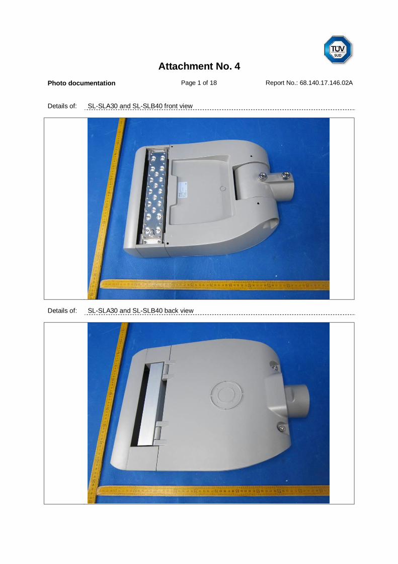
Attachment No. 4Photo documentation Page 1 of 18 Report No.: 68.140.17.146.02A
Details of: SL-SLA30 and SL-SLB40 front view
Details of: SL-SLA30 and SL-SLB40 back view

Attachment No. 4Photo documentation Page 2 of 18 Report No.: 68.140.17.146.02A
Details of: SL-SLA60 and SL-SLB80 front view
Details of: SL-SLA60 and SL-SLB80 back view

Attachment No. 4Photo documentation Page 3 of 18 Report No.: 68.140.17.146.02A
Details of: SL-SLA90 and SL-SLB120 front view
Details of: SL-SLA90 and SL-SLB120 back view

Attachment No. 4Photo documentation Page 4 of 18 Report No.: 68.140.17.146.02A
Details of: SL-SLA120 and SL-SLB160 front view
Details of: SL-SLA120 and SL-SLB160 back view

Attachment No. 4Photo documentation Page 5 of 18 Report No.: 68.140.17.146.02A
Details of: SL-SLA150 and SL-SLB200 front view
Details of: SL-SLA150 and SL-SLB200 back view

Attachment No. 4Photo documentation Page 6 of 18 Report No.: 68.140.17.146.02A
Details of: SL-SLA180 and SL-SLB240 front view
Details of: SL-SLA180 and SL-SLB240 back view

Attachment No. 4Photo documentation Page 7 of 18 Report No.: 68.140.17.146.02A
Details of: SL-SLA210 and SL-SLB280 front view
Details of: SL-SLA210 and SL-SLB280 back view

Attachment No. 4Photo documentation Page 8 of 18 Report No.: 68.140.17.146.02A
Details of: SL-SLA240 and SL-SLB320 front view
Details of: SL-SLA240 and SL-SLB320 back view
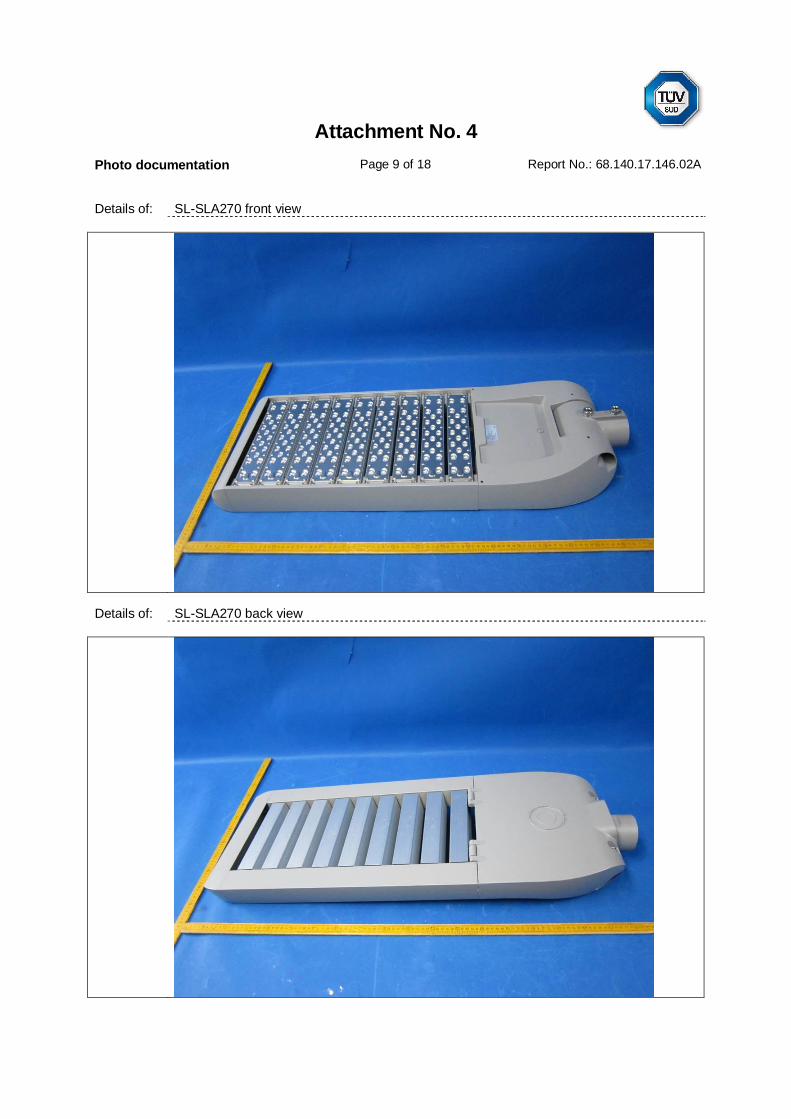
Attachment No. 4Photo documentation Page 9 of 18 Report No.: 68.140.17.146.02A
Details of: SL-SLA270 front view
Details of: SL-SLA270 back view

Attachment No. 4Photo documentation Page 10 of 18 Report No.: 68.140.17.146.02A
Details of: SL-SLA300 front view
Details of: SL-SLA300 back view

Attachment No. 4Photo documentation Page 11 of 18 Report No.: 68.140.17.146.02A
Details of: Internal view for models SL-SLB40 and SL-SLB80Including one LED driver (type A)
Details of: Internal view for models SL-SLA90, SL-SLA120, SL-SLA150, SL-SLB120 and SL-SLB160Including one LED driver (type B)
Gland used ascord anchorage
Quick connector

Attachment No. 4Photo documentation Page 12 of 18 Report No.: 68.140.17.146.02A
Details of: Internal view for models SL-SLA30 and SL-SLA60Including one LED driver (type D)
Details of: Internal view for models SL-SLA180, SL-SLA210, SL-SLB200 and SL-SLB240Including two LED drivers (type D + type B)
Gland used as cordanchorage
Gland used ascord anchorage

Attachment No. 4Photo documentation Page 13 of 18 Report No.: 68.140.17.146.02A
Details of: Internal view for models SL-SLA240, SL-SLA270, SL-SLA300, SL-SLB280 and SL-SLB320Including two LED drivers (type B + type B)
Details of: LED driver view (type A)
Gland used ascord anchorage

Attachment No. 4Photo documentation Page 14 of 18 Report No.: 68.140.17.146.02A
Details of: LED driver view (type B)
Details of: LED driver view (type D)

Attachment No. 4Photo documentation Page 15 of 18 Report No.: 68.140.17.146.02A
Details of: LED driver view (type E)
Details of: LED driver view (type F)

Attachment No. 4Photo documentation Page 16 of 18 Report No.: 68.140.17.146.02A
Details of: Earthing terminal view
Details of: Earthing terminal internal viewRemark: the terminal block use the spring pin connect to metal enclosure.

Attachment No. 4Photo documentation Page 17 of 18 Report No.: 68.140.17.146.02A
Details of: Connector for LED module view
Details of: LED module view for all models
DC connector
Wire connector

Attachment No. 4Photo documentation Page 18 of 18 Report No.: 68.140.17.146.02A
Details of: LED module side view for all models
Details of: LED module internal view for all models
***End of Report***