be nps-69ps-78- naval postgraduate school … · naval postgraduate school omonterey, california...
TRANSCRIPT
be NPS-69PS-78-
NAVAL POSTGRADUATE SCHOOLoMonterey, California
EFFECTS OF DISSIMILAR METAL COUPLING,POTENTIAL DISTRIBUTION, AND TEMPER CONDITIONON GALVANIC CORROSION OF 5086 ALUMINUM ALLOY
IN SYNTHETIC SEAWATER
Jeff Perkins, J. S. I.,ike, and K. J. GrahamMaterials Science and Chemistry Group
Naval Postgraduate SchoolMonterey, California 93940
January 1978 DDcTechnical Report No. 5 -.To the Office of Naval ResearchContract No. N00014-77-WR-70215 MAR 7 1973NR-036-120
'i' ,'.Ouction in whole or ir part is permitted for any purpose of theStates Government.
DISTR'IBUTIONS;-
NAVAL POSTGRW,!UATE SCHOOLontevsy, Califoi-nla
Rear Admial T. F. Dedmn Jack R. BorstingSuperi rtendent Provost
The work reported herein was supported by the Office of Naval Research,fletallurgy Program Office, Code 471. Arlington, VA, 22217, through ContractNo. M00014-77-WR-70215, NR-036-120.
Reproduction of all or part of this report is authorized.
This report was prepared by:
Associate Professor ofNclchanical Engineering
Reviewed by: Released by:
PauT- . Mano Aotting Chairmn K M oesDepartment ofl hanica! Engineering Actring Dean of Research
119CURITY CLASSgI(CA7101 OF THIS PAOR tMhO. OS A ___________________
RZAD DIUCINWEPNTDOCUENTAT : PAE a'ong COMPLETiNG
Efcts of nis ia a Cu ng, Potential
~e lwatr __4Y TechnclRptNo
Coroio of 5 6I Aluminum~.u Allo Sin Sytetc . pffFfAMII4M3,61116 ."Rrmalk
Mat ias S ie an d Ch mi tr
troup tCod '59P
Naval Postgraduate School, Monterey, CA 93940 Progrjec emnt KR122 58-011, CONTROLLI"G QFFICW NAM9 AND AODESSIma
Office of Naval Research. Metallurgy Progra(/ JanwW187Office, Code 471, Arlington, VA 22217
14. T ONYMuII l Ilm# Cgna.aOng ISsicumrvt' CAS (es in*.
Unclassified
I I"T(ofWsPAMek ILAI O
Approved for public release; distribution unlimited.Reproduction in whole or in part is permitted for any purpose of tneUnited Sitates Giovernmnent.
It. SUPPLEMENYARY NOTELS
It, KE'V WORD$ 'C afjwum .. ,e.. odd * IV... d .*N -
lalvu'ic corrosion. 5086 a1 winum alloy
IfASUACT (COMINN 0 f.dd FO 06 ft g000 OW dr aw WpSeft ErnA,)
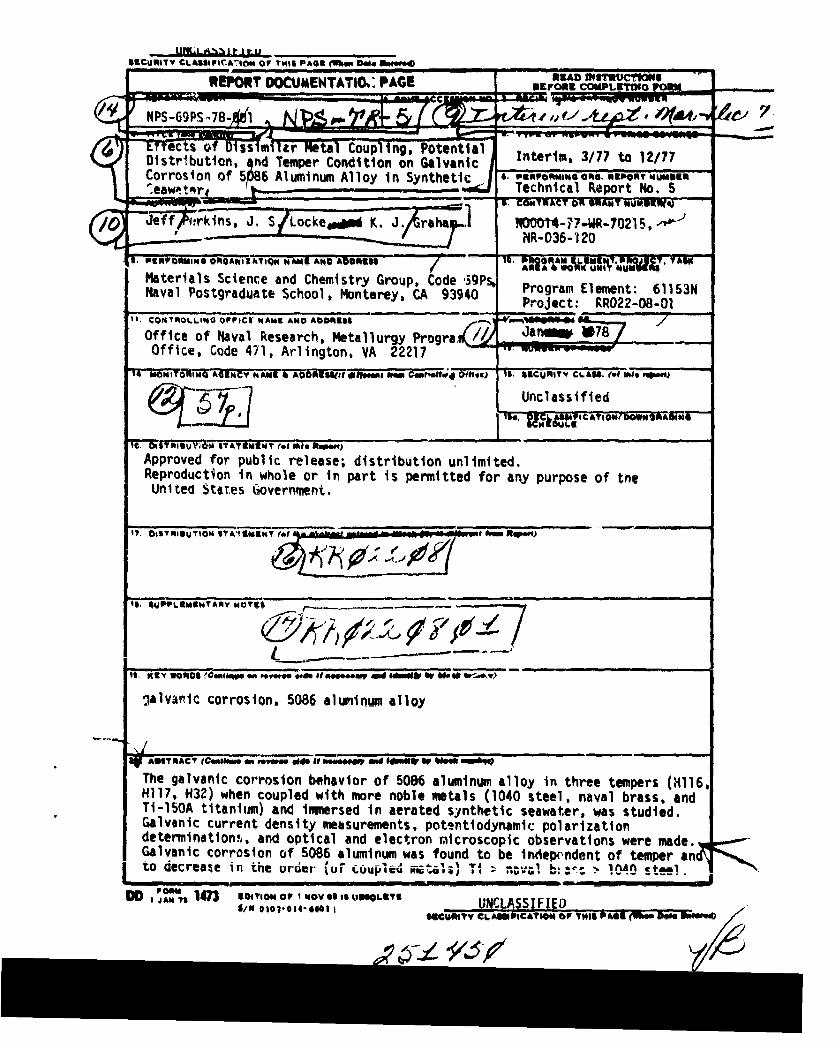
The galvanic corrosion behavior of 5086 aluminum alloy in three tempers (H116,H117, H32) when coupled with more noble metals (1040 steel, naval brass, andTi-150A titanfiam) and immersed in aerated synthetic seawater, was studied.Galvanic current density meaisurements, patentiodynamir. polarizationdetermination', and optical and electron mlicroscopic observations were made.Galvanic corrosion of 5086 aluminum was found to be independent of temper ato decreate in the urder Nif co.upled fiiail31 --; n;val br:,! >- 1040 SteeW.
AN 7) 9/14 O OVSt ISLT UNCLASSIFIEDiN 010014-iOI I CUmNTY CLAMIuCATIOW Of' TNJI P601 t~ ?= a 5;
UlaAm1F1Ff..1LU111TV CLASIPICATION OF TISB PA6SAWm 011M 80
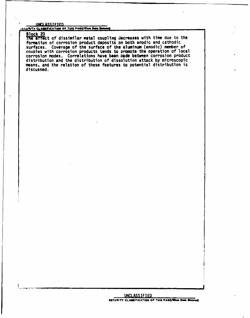
Block 201TFiYeiMt of dissimilar netal coupling decreases with time due to theformation of corrosion product deposits on both anodic and cathodicsurfaces. Coverage of the surface of the aluminm (anodic) member ofcouples with corrosion products tends to promote the operation of localcorrosion modes. Correlations have been imde between corrosion productdistribution and the distribution of dissolution attack by microscopicmeans. and the relation of these features to potential distribution isdiscussed.
UNCLASSIFIED
11111URIT CLASSNIFFICATION OF THIS WA63tMem DWO Awe
Effects of Dissimilar Metal Coupling, Potential Distribution,and Temper Condition ci G ,lvmntc Corrosion of 5086
Aluminum Alloy In Synthetic Seawater
Jeff Perkins, J.S. Locke. and K.J. Graham
ABSTRACT
The galvanic corrosion behavior of 5086 aluminum alloy in three tempers
(H116, Hl17, H32) when coupled with more noble metals (1040 steel, naval
-brass, and Ti-150A titanium) and imnrsed in aerated synthetic seawater,was studied. Galvanic current density measurements, potentiodynamic polari-
zation determinations, and optical and electron mtcrc-copic observations
were made. Galvanic corrosion of 5086 aluminum was found to be independent
of temper and to decrease in the order (of coupled metals) Ti > naval brass
> 1040 steel. The effect of dissimilar metal coupling decreases with time
due to the formation cf corro0ion product deposits on both annuic and
cathodic surfaces. coverage of the surface of the aluminum (anodic) membersi couples with corrosion produ'ts tends to promote the operation of localcorrosion modes. Correlations have been made between corrosion productdistribution and the distribution of dissoltion attack by microscopicmeans, and the relation of these features to potential distribution isdiscussed.
av" N "" D D C
... ..... MAR 7 1978B..... .................. .W O ,

CONTENTS
INTRODUCTION .... . 1
1. Some Problems with 5000 Series AluminumAlloys in Marine Applications .... . 1
2. Galvanic Corrosion . . . . . . . . . . ............ 3
3. Methods to Study Galvanic Corrosion. ..................... 4
4. Objectives of this Research .............. . . . . .. . 5
EXPERIMENTAL PROCEDURES . . . ... .................... .. 7
1. Materials .7............. ................ 7
2. Exposure of Proximate Couples ....... . . . . ... . 7
3. Galvanic Current Density Measurents . ...... . . . . . . . 9
4. Potentiodynamic Polarization Measurements....... . . . . . . 10
RESULTS AND DISCUSSION ..... ..................... . . . . . . . 11
1. Potentiodynamic Polarization Behavior .... ............... 11
2. Galvanic Current Density ....... ..................... 12
3. Morphology and Distribution of CorrosionPf....... on Proxinfie Galvanic Couples . . . . . . . .... . . ...
A. Morphology and Distribution of PrecipitateFormations on Cathodic Members of Couples . . . . . . . . . .. 15
B. Morphology and Distribution of CorrosionProducts on Aluminum Alloy Anod( Members of Couples .. ..... 16
C. Distribution of Dissolution 1; Aq9 . .. ... .......... 18
CONCLUSIONS .......................... ............ 20
REFERENCES ...... .. ... ......... ................................. 21
LIST OF FIGURES ..... ... ... .............................. 23
FIGURES . . . . . . . . . . . . . . . . . . . . . . . . . . . . . . . . . . 26
1. Fome Problems with 5000 Series Aluminum Alloys in Marlne Applications
The use of aluminum for marine applications dates back to 1890 when the 5.2 m
vessel "Zepher" was launched. By 1960 more than 1000 merchant ships were using
substantial amounts of aluminum for structural applications. In contemporary U.S.
Navy ships, most of the superstructure above the main deck is made of aluminum,
and many other uses for gluminum art found throughout the ship. For example, the
USS DEWEY (1959) was built containing about 167 tons of aluminum, mostly 5456-H321
plate and 5086-H32 sheet. Contemptrary aircraft carriers such as the USS INDEPENDENCE
(1958) carry about 900 tons of aluminum while a GEORGE WASHINGTON class submarine
(1959) has about 20 tons of aluminum. Additionally many all-aluminum craft, such as
submersibles and patrol boats, have been and are still being built. Since the use
of aluminum saves weight, we can expect use in ever-increasing quantities, especially
in forthcoming generations of high speed surface effect ships and craft.
Aluminum has good corrosion resistance to the atmosphere and to many aqueous
media. It is a reactive metal, being very active in the EMF series, but develops
an oxide surface film that protects it in many environments; this behavior can be
inferred from examination of the Pourbaix (potential-pH) diagrams for aluminum.
Thus the corrosion behavior of aluminum is determined essentially by the formation
and behavior of a passivating layer of oxide film. The structure of the oxide film
is generally complex. It may consist of A1203 alumina, A1203.H20 bohmite, A1203.
,n2u bayerite or A12u3.jH2u hydragilite (1). Hart tj showed that il. m0
pure aluminum immersed in water (at temperatures less than 600C) develops in three
stages: first amorphous hydroxide is formed, then orthorhombic y-AO-0H and then
bayerite. The final film according to Hart is then made up of three layeri. The
film of "Al2 31" is estimated to be 20°A to 1000A thick when formed in air.
Ali:,inum alloys with Mg content up to three percent have corrosion resistance
about the same as pure aluminum and low mechanical strength (3). Increasing the
amount of Mg increases the strength of the alloy but lowers its corrosion resistance
somewhat. This is due to the magnesiun being more anode than the aluminum. The
aluminum alloys designated 5086, 5456 and 5083, containing four to five percent
magnesium, are used extensively in marine vehicle applications. In addition to
corrosion resistance, they have good weldability and high strength to weight ratio
(3). Typically, the strain hardened tempers designated as 5086-H32, 5083-H321 and
5456-H321 were selected.
It Is well-known by naval architects and marine engineers that galvanic corrosiun
tends to occur when (5XXX series) aluminum alloys are coupled with other structural metals,
which are typically more noble than aluminum. Therefore, features for prevention
I
of this type of corrosion are typically incorporatJ Into the designs of marine
vehicles using aluminum, for example, through the use of insulating materials to
prevent electrical contact and piint coastings to prevent electrolyte contact with
a dissinilar metal. However, for a variety of reasons galvanic corrosion problems
still ot;cur (4,5). For example, Strasburg (4) reported on the considerable expend-
iture o' maintenance effort required to repair damage at the aluminum superstructure
to steel de.k Interface on destroyer type ships, and also noted that there may be
extensive corrosion damage on aluminum plate adjacent to pipe penetrations. Corrosion
problems were also encountered in the bil2e areas of aluminum-hulled (5456-H321)
patrol bcats used in Vietnam (5). These boats experienced extensive exfoliation
corrosion. The conditions that existed in the bilge areas of the boats were extremely
favorable to the tnitiation of pitting corrosion. Pitting would start and then give
way to exioliation or intergranlar corrosion once the interior metallurgical struc-
ture of thu alloy was exposed.
Exfol-ation susceptibility of 5456-H321 is considered to be related to an elon-
gated grain structure with relatively continuous precipitation of A13Mg2 phase along
the gr&in boundaries (5). The H32 and H321 tempers apply to products which are
strain hardened and then stabilized by a 'low-temperature heat treatment to slightly
lower the st,'ength and to increase ductility and stress-corrosion resistance, a process
which results in a microstructure in which the precipitate is present in a continuous
line. Doig aid Edington (6). in their work with a Al-7.2 percent Mg alloy, explained
that the micrcstructure may be divided into three regions: the grain boundary pre-
cipitate of Al.Mg2, its associated solute depleted zone, and the matrix with bulk
composition. The corrosion response is detemined by the respective e;ectrochemical
properties of tiese three regions. The A13Mg2 phase is more anodic than the matrix
or the adjacent solute-deplet'4 zone (6), so that this precipitate is preferentially
attacked, and tht corrosion products which form occupy more space than the metallic
compound, and therefore exert a force on the metal. This causes aelamination, the
phenomenon called "exfoliation".
To prevent exfoliation, the continuous network of the Al-Mg precipitate must be
broken up. To do ihis Reynolds and Alcoa recently developed the H116 temper and
H117 temper respectively, for both 5456 and 5086 alloys. The H116 and H117 tempers
apply to products wkich are strain hardened less than quarter-hard and do not undergo
a stabilizing heat t,'eatment. These alloys both have a grain structure predominately
free of continuous gumin boundary network, as opposed to the continuous grain boind-
ary network found in v.he H32 and H321 tempers. Even with these tempers, continuous
precipitate (sensitization) can be induced by natural aging. Since 5456 contains
five percent Mg while 1086 contains only four percent Mg, this problem occurs more
2
readily In 5456 (7). and work by Czyryca and Hock (8) suggests that the H116 temper
produces material less susceptible to natural aying. In general, the use of the
H116 and H117 tempers should give improved performance with respect to exfoliation
and lntergranular corrosion. However, corrosion will still occur whenever galvanic
couples are allowed to exist.
Even with the metallurgical advances menxioned above, and with other advances
in corrosion control, galvanically induced corrosion between Al alloys and other
metals is still a widespread problem in marine applications. In many cases the most
efficient design requires the use of dissimilar metals, since criteria such as
strength, fatricabllity, cost, availability and appearance are often weighed more
heavily than corrosion control in the design process (9). Numerous examples can be
cited. such as pipe penetrations through aluminum bulkheads, which usually brings
steel and aluminum together. Watertight doors which penetrate the aluminum super-
structure also provide a place for galvanic corrosion to take place. For strength
reasons, brackets on aluminum bulkheads usually involve steel nuts and bolts. Heavy
equipment mounted above the main deck usually requires steel for support and provides
another opportunity for galvanic corrosion. To combat the severe corrosion that was
occurring at the aluminum superstructure-steel deck interface, the U.S. Navy is low
using an explosively bonded joint for repair of old corroded joints and for instal-
lation on new construction. The use of explosive bonded material eliminates the-hnk-al 9revice ouvwmilly preSent et Zhe joint. However, when exposed to a cor-
rosive marine environment, corrosion does occur preferentially at the bond interface
as was shown by Keelean (10). The extent to which this detracts from the mechanical
properties of the bond is unknown, but may be expected to be significant.
2. Galvanic Corrosion
Galvanic corrosion occurs when two or more metals in electrical contact are
also in contact through an electrolyte. To predict the behavior of a metal in a
galvanic couple, galvanic series are often used. Such series are const, ucted by
Is-"Ing, , U.. .erent nfL@ia according to their equilibrium potentials in a specific
environment. For example, a galvanic series of some metal% in flowing sea water is
given by LaQue (11). The metal with the more active potential becomes the anode,
while the metal witi, the more noble potential becomes tie cathode when two dissimilar
metals are coupled. The damage incurred by coupling the two metals is dependent on
many factors, one of which is separation on the galvanic series (open clrcuit potentia
difference). However, it is not possible to simply assume that the further apart
(greater the potential difference), the greater the damae; it is essential to also
consider the area ratio of the two metals in the particular situation, the polarizatic
behavior of the metals, and the conductivity of the electrolyte. The simple approach
3

bCICL.LIlV HPULGIMI UoeU Un PU31I~lUFI In a YGIVaflIL. bel M Lanl U9 2 Very puur inut~kurof galvanic corrosion rates, as pointed out recently by Hansfeld and Kenkel (12).
When two metals in a electrolyte are coupled, both metals are polarized so that
each corrodes at a new rate; the more active metal corrodes more and the more noblemetal corrodes less. The polarization is defined as the extent to which the potential
of a metal is changed due to the induced galvanic current. The more active intal ispolarized along its anodic polarization curve in the direction of increasing potential
(becoming more noble in potential); the more noble metal is polarized along its cathodic
polarization curve in the direction of decreasing potential (becoming more active in
potential). Thus the respective behavior of the metals as they are polarized is
extremely important in determining the final eqvllibrium potential between the twometals, the galvanic corrosion current, and the ensuing metal dissolution of the
anode.
3. Methods to Stud Galvanic Corrosion
Techniques for predicting galvanic corrosion include electrode potential deter-minations, current measurements, and polarization techniques. As pointed out by
Baooian (13), only by using all these methods can an overall characterization of the
behavior of the metalsin a galvanic couple be completed.
a. Potential Measurements
Potential measurements are generally used to construct a galvanic series which
can be quite useful when the polarization characteristics for the metals are
straightforward (14). Howeverthere are other factors which can significantly
decrease the usefulness of this method. For example, if a surface film forms so that
the metal remains passive, then that film will influence the corrosion rate over a
wide range of potentials. Also, the potential of a metal may vary with time, thus
changing its position on the galvanic series. Additionally, the polarizability
of the metal could change according to the environment and time. Thus the simple
measurement of the corrosion potential, while useful, does not yield enough infor-
mation on which to base a orediction of aalvanic nrrnsinn hahavior
b. Current Measurements
There are various ways to measure the current flowing between two electrically
coupled dissimilar metals which are immersed in an electrolyte. The first and most
obvious way is to measure the voltage drop across A known resistance. This methodis generally considered unsatisfactory because the two metals are not at the sae
potential but are separated by the resistor voltage drop. This causes t e mesured
current to be less than the actual galvanic current. Additionally, the reduced
polarization associated with this situation may induce misleading conclusions when
comparing results obtained for various dissimilar metal couples which have
4
different polarization characteristics. Early attempts to remove the effect of
the resistor wert described by Brown and Mears in 1938 and referenced recently
by Mansfeld and Kenkel (12); basically, the resistor effect can be accommodated
by using a set of switches and balancing circuitry. However, this introduces
transients when the system is not in balance, which requires a recovery period,
and cannot be used for continuous observations, Numerous investigators have had
success using clip-on-millammeters to measure the current through low resistance
wire connecting the coupled metals. However, this method is typically limited to
currents greater than 300 .,A. The systems currently in greatest use take advantage
of operational amplifiers to maintain a zero potertial difference between the twodissimilar metals while measuring by some means the current required to do this.
The balancing current then equals the galvanic current. An "electronic zero resist-
ance ammeter with instantaneous null characteristics" was developed by Henry and
Wilde; the principle of operation is based on the use of an operational amplifier
to replace manual balancing, with the galvanic current read on a microammeter.
It is also possible to use a potentiostat as a zero resistance ammeter (12), in
whlcn case, with the potentiostat set at zero millivolts applied potential, thE
galvanic current can be read directly on the current meter of the potentiostat.
c. Poiarization Measurements
Polarization behavior Is critically important relative to corrosion rates, since
single metals that corrode uniformly may undergo severe localized corrosion when
polarized, or may become passive. Therefore it is important to know the shape of
the respective potential versus current curves in order to be able to predict the
equilibrium potential and current density of coupled metals. This may be done by
adding the currents of Zhe cathodic curves to get a total cathodic curve and the
currents of the anodic curves to get a total anodic curve. The intersection of the
total anodic and total cathodic curves gives the equilibrium potential and current
density of the couple. Or, if the potential of the couple has already been measured,
then the current density may be predicted by finding the interaction of the horizontal
line equal to the potential and the Tafel slope of one of the particular metals.
4. Objectives of this Research
The specific objective of the present research was to investigate and characterize
the behavior of aluminum alloy 5086 when coupled with other, more noble, metals andImersed in seawater. In so doing, it was intended to add to the understanding of
the basic mechanisms involved in galvanic corrosion situations. 5086 aluminum was
selected because of its widespread use in marine applications. Also, it was ofintereoct tn rnni-re the b.ka'i.r nf ... 4#-,. ..-. f -- -1 1- - .J-•.,w.. -_ . .. .- -_* - - _- - - . - W - . W a U IUJr , ,1% Il U 111 I 1(a
recently developed new tempers intepded to reduce exfoliation susceptibility.
5
The genera' plan of attack was to corrode bimetallic couples in synthetic sea-
water for various lengths of time while monitoring the electrochemical behavior.
after which the corrosion product formation and distribution would be studied nmcro-
scopically and microscopically. Polarization curves and galvanic cuirent density
data would be used to gain an understanding of the dynamics associated with the
different couples and to correlate macroscopic and microscopic data with the electro-
chemical processes that had taken place.Three metals noble in poteatial to aluminum were selected as the cathodic counter
electrode, based on their open-circuit potential positions in the galvanic: series
,for flowing seawater. The three were selected so that one (steel) was near aluminumin potential, one (titanium) was near the noble end of the galvanic series and the
third (brass) was roughly half-way in between.
6

EXPERIMENTAL PROCEDURES1. Mal-.rials
Aluminum alloy 5086 was obtained in H32, Hl16, H117 tempers. The 5086-H32
alloy was in the form of 0.483 cm thick sheet, manufactured by Alcan Aluminum Corp.
The 5086 H116 alloy was in the form of 0.483 cm thick sheet, manufactured by Kaiser
Aluminum. The 5086-H117 alloy was obtained on request from Mare Island Naval Ship-
yard, Vallejo, CA, in the form of 1.427 cm thick plate, not marked as to the manu-
facturer. 5086 aluminum alloy has a specified nominal percentage chemical composi-
tion of 0.45 Mn, 4.0 Mg, 0.15 Cr, balance aluminum, with compositional limits of 0.2
to 0.7 Mn, 3.5 - 4.5 magnesium, 0.05 - 0.25 Cr, 0.5 iron, 0.4 silicon, 0.211 zinc,
0.1 copper, and 0.15 titanium.
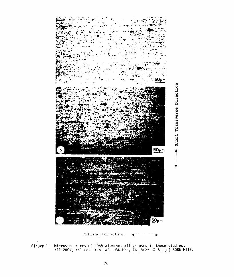
The microstructures of the 5086 Al alloy in the respective as-received tempers
are shown in Figure 1. These structures are in agreement with those published by
other researchers [6,9,11,12]. The 5086-116 microstructure consists of a discon-
tinuous network of precioitate, while the 5086-H32 has a morc continuous network.
The microstructure of the 5086-HI17 seems to contain a somewhat more continuous
precipitatL network than 5086-H116, for the same metallographic preparation, which
is not normally expected and may be caused by prior senitization. It has been
reported that there is a greater tendency for material in the 11117 temper to become
sensitized (than material in the H116 temper) (8). In any case, these microstruc-
tural variations will later prove to have little effect on the response of the
aluminum alloy studied in these present experimental conditions. The cathodic
metals used were 1040 steel, naval brass, and Ti-150A titanium.
2. xpo " . Proximate Couples
The ry purpose of these exposures was to deploy various proximate, planar,
bimetallic couples in synthetic seawater in order to subsequently study corrosion
product morphology and distrioution. The anodic member of the proximate couples
was in all case_ one of the three temper types of 5086 Al, the cathodic member
was one of the three other metals (steel, brass, or titanium). Testing was accom-
plished by mechanically mating the two metals in such a way that a reproducible and
crevice-free interface was produced. The samples were so designed that they could
subsequently be examined in a scanning electron microscope (SEM) without disturbing
their corrosion product formations. In the design of all test procedures, the
guidelines set down in National Association of Corrosiun Engineers Standard TM-01-69
were carefully follcwed (15). The exposure apparatus consisted of an array of
1000 nil beakers (Figure 2) each filled with 1000 ml of syntheti' seawater prepared
according to Kester et al (16).
7

this was accomplished by pumping air from an aquarium type pump through a system
of rubber hose into each beaker via a small glass tube. Volume control of the
air was accomplished by adjusting screw type clamps located on each hose, with
the pump hose, vented to the atmosphere, used to reduce back pressure. The beakers
were covered with watch glasses to prevent contamination and reduce evaporation.
Hydrogen ion concentration was monitored with a Photovolt Corpora-cn Model 115
Electronic pH meter. A Beckman pH.9.1 buffer was used to standarize the instru-
ment prior to use. pH measurements averaged 8.22 and varied from 8.1 to 8.5.
Conductivity was monitored with a Barnstead Conductivity Bridge Model PM-7OCM and N
a sensing electrode set as shown in Figure 6. The bridge and electrode set combina-
tion were calibrated using a 0.020 normal KCl solution. A correction factor of
404.cm-l was computed. This factor was divided by the bridge reading in ohms to
get conductivity in millimhos per cm1. Conductivity measurements averaged 48.6
miilimhos per cm and varied from 47.0 millimhos per cm to 49.9 millimhos per cm.
The temperature of the corrosive medium was allowed to fluctuate with room temperature,
which averaged about 21.5 0C and varied from 18*C to 24'C, with average day/night
variations of about + 1.5C.
A Cambridge Model S4-lO Stereoscan Scanning Electron Microscope (SEM) was
utilized to study thi corrosion product morphology and distribution and the damage
resulting from the corrosive attack, together with a Princeton Gamma Tech PGT-1000
energy-dispersive x-ray spectrometer, and various light microscopes and macrophoto-
graphic equipment.
Nine couple types were studied as follows:
ANODE CATHODE
1. 5086-H32 Al 1040 Steel
2. 5086-H32 Al Naval Brass
. 5086-H32 Al Ti-150A Titanium
4. 5086-Hl16 Al 1040 Steel
5. 5086-H116 Al Naval Brass
6. 5086-HI16 Al Ti-150A Titanium
7. 5086-H117 Al 1040 Steel
8. 5086-H117 Al Naval Brass
9. 5086-H117 Al Ti-150A Titanium
The six different metals involved were milled into test coupons 1 cm by 1 cm
by 0.48 cm. In the case of the Al, at least one face Wds left in the as-received
condition so that it could later be mounted exposed to the synthetic seawater with
8

the direction of rolling horizontally oriented. Individual coupons were fir.t
mounted in a cylindrical plastic mount, in thermosetting resin, with one of the
1 cn by 0.48 cm sides exposed. The exposed side was lightly sanded flat on a 180
grit belt sander. The coupon was then broken out of the plastic sanding mount, and
a bimetallic couple with a flat, tight, elec.ricaliy conductive joint formed by
joining the sanded surfaces of pairs of di-oimilar metals. A special mounting ring
device was used to form the bimetallic couple, as shown in Figure 2b. This consisted
of a metal moulding ring into which were drilled and tapped two diametrically opposed
holes; thro,,gh these holes were threaded two 4-40 thread screws which were tightenad,
using a mi, I-torque wrench, to 0.7N'cm, therefore pressing the metals together with
a constant and reproducible stress. Thermosetting resin was then poured into the
ring and allowed to harden. After the resin had set, the screws were removed and
the mounted (ouple removed; the finished couple is shown to the right in Figure 2b.
The sample was then sanded with a 50 grit belt sander on both the front and back to
remove excess plastic. This was done on the front only to the point that metal mas
exposed. On the back however a large portion of the plastic was removed to thin the
sample so that it would more conveniently fit on the SEM stage; the sample back wa3
ground so as to expose the back of the couple, and allow direct contact to the SEM
stage. Grinding was completed by sanding the face of the sample to an 000 grit
finish. The samples vrere then cleaned ultrasonically in tap water, rinsed in alcohol
and blow dried with warm air. The exposed backs of the samples and the holes left
by the bolts were filled with paraffin prior to exposure. The above procedure was
ible to produce a high quality, crevice-free, planar cathode: anode joint as
shown in. Figure 3a.Different samples were immersed for one day, one week, two weeks, three weeks,
and eight weeks. After the specified exposure period the individual sample was
removed from the synthetic seawater and dipped in distilled water for about three
seconds. After dipping, photographs were taken of the condition of the sample while
still wet and also after dryir,9, using both a low power light microscope and a 35mm
macro camera. The sample wvs then examined in the SEM, using the energy dis-
persive X-ray spectrometer when required. After initial SEM observations, the
samples were ultrasonically cleaied of corrosion products using distilled water and
a commercial cleaning product called "Micro" mixed to the manufactures recommenda-
tions. After cleaning, they were rinsed in distilled water, rinsed in alcohol,
and air dried. Observations of corrosion damage were then made using the SEM.
3. Galvanic Current Density Measurements
The purpose of these measurements was to determine, for separated bimetallic
couples which were as similar as possibl3 geometrically to the proximate couples,
19
the galvanic current between the dissimilar metals. These measurements would give
an Indication of the corrosion rates of the various couples, which could then be
correlated with surface observations made on the proximate couples and with poten-
tiodynamic polarization measurements.
The corrosion cells used for these measurements consisted of beakers filled with
1000 ml of synthetic seawater. Oxygen concentration was maintained at a constant
saturated level through the use of an air sparging system arranged as previously
shown for the phys.cally coupled cells, and the beakers covered with watch glasses.
A Princeton Applied Research Model 173 Potentiostat/Galvanostat was used as a zero
impedance ammeter, and galvanic current was measured as a function of time for all
nine couple types. The samples for these measurements consisted of separately mounted
anode and cathode test coupons, otherwise prepared exactly as for the proximate
couples, with provision made for electrical contact to and between the dissimilar
metals by threading copper wire into the side of the mounted coupon6 and sealing
with paraffin.
4. Potentiodynamic Polarization Measurements
The purpose of these measurements was to obtain the characteristic anodic and
cathodic polarization curves for the various metals being tested. This data would
be useful in making interpretations of the galvanic current density data and the
observations of corrosive attack on the coupled samples. A Princeton Applied ResearchModel 173 Potentiostat/Galvanostat was used, with a standard polarization cell and
calumel reference electrode. The auxiliary electrodes were graphite rods. Prepara-
tion of the polarization test coupons was identical to that used for the measurement
of galvanic current.
10
RESULTS AND DISCUSSION
1. Potentiodynamic Polarization Behavior
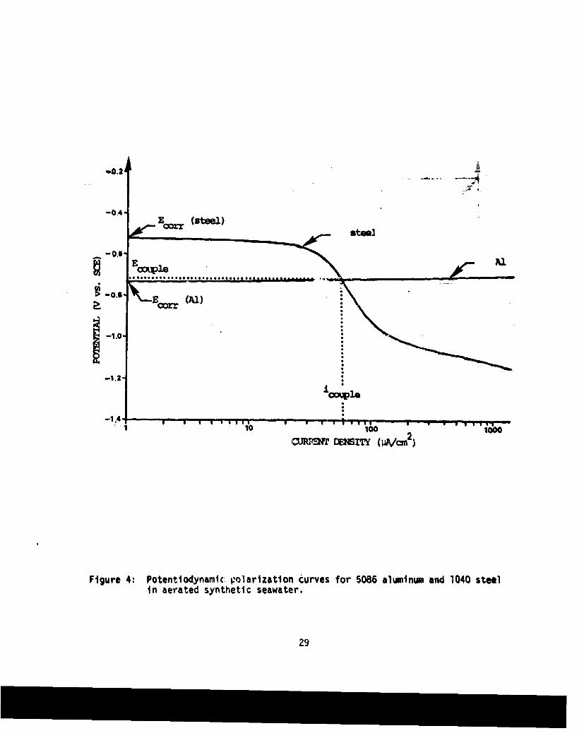
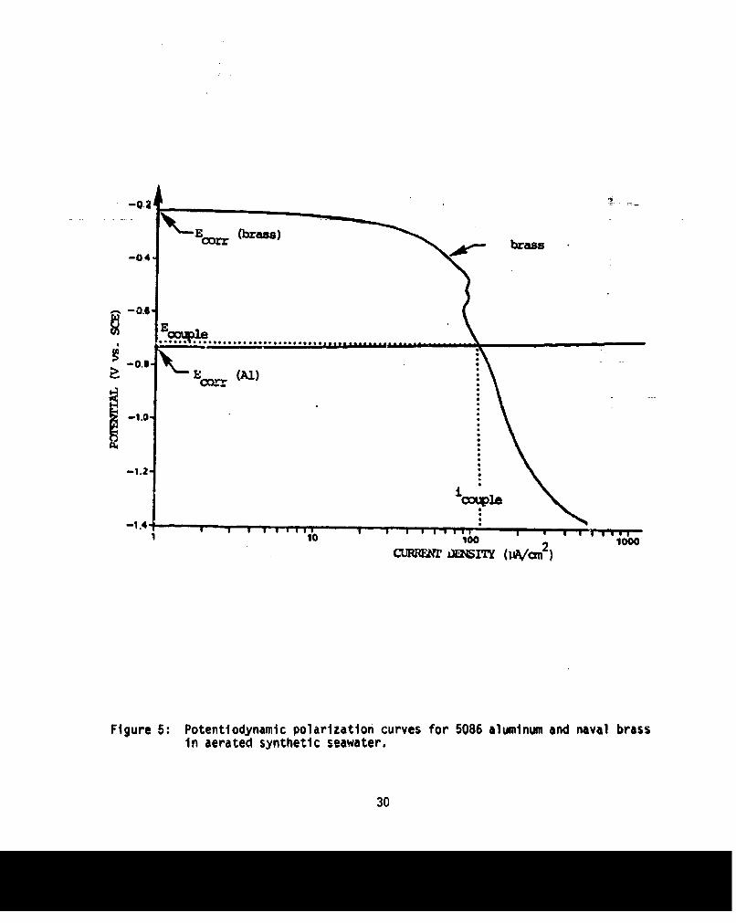
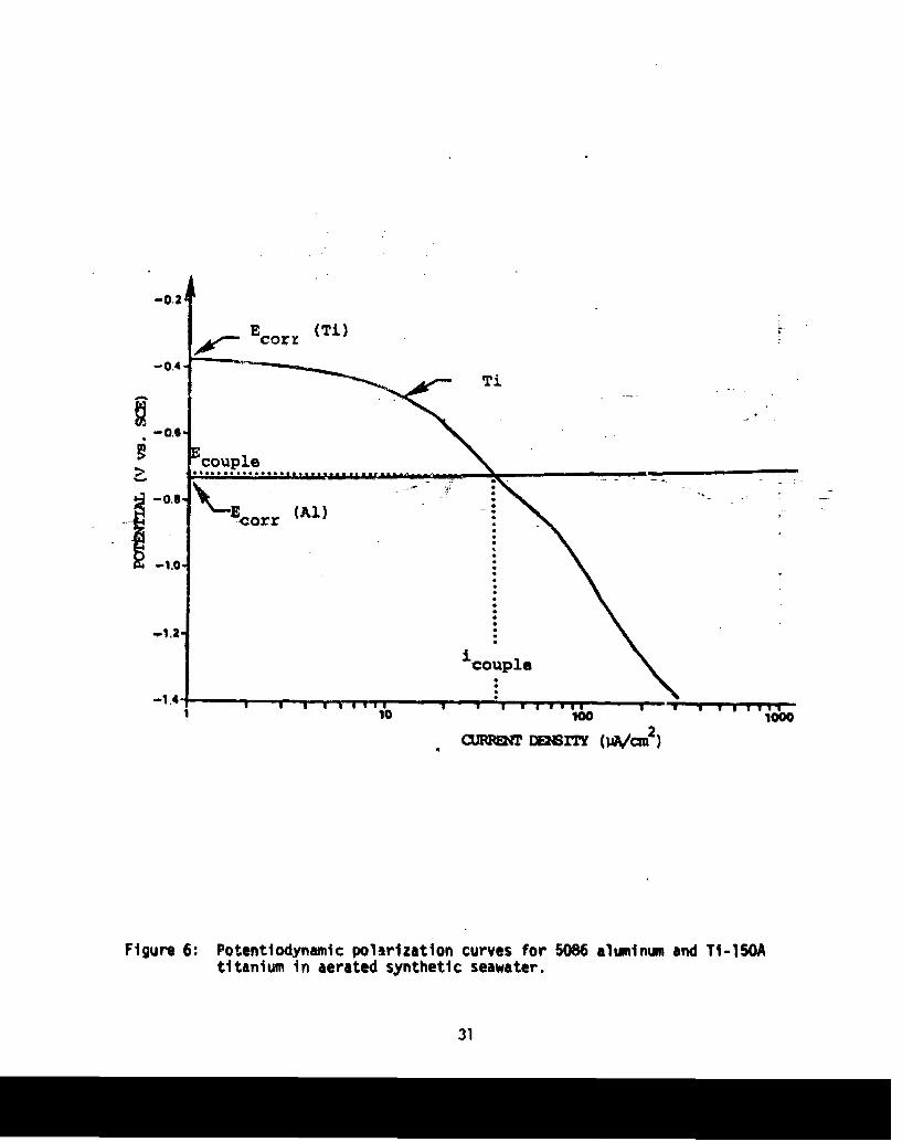
Potentiodynamic polarization curves for the six test metals are shown in Figures
4-6. The anodic polarization curves were essentially identical forall three tempers
of the 5086 Al alloy, indicating that the tendency of this Al alloy to corrode in a
galvanic couple may not be dependent, at least macroscopically, on its temper condi-
tion. Also shown in Figures 4-6 are the respective cathodic polarization curves for
the three more noble metals deployed in the galvanic couples. The intersection points
obtained allow an approximation of the galvanic current density which would be ex-
perienced for a given couple, 1 couple' and the corrosion rate for the anodic metals
can also be predicted. The predicted galvanic current density, 1couple' for the
three types of couples, taken from Figures 4-6, are: 112 pA/cm for the brass/Al
couple, 60 pA/cm 2 for the steel/Al couple, and 37 pA/cm 2 for tho TI/Al couple.
This ordering of 1couple (brass/Al > steel/Al > Ti/Al) would not be obvious from the
relative position of these materials in galvanic series for seawater, where thepotentials of the three cathodic materials are ordered Ti > brass > steel. The
observation that galvanic series open-circuit potential differences cannot be
taken as an indicator of dissolution rates has recently been demonstrated by the
extensive work of Mansfeld and Kenkel (17), who recommend that galvanic series be
considered as only "very qualitative guidelines".
Also from the single metal polarization curves, the equilibrium potentials,
Ecorr, of the Independent metals is determined, and Ecouple for each couple type
can be predicted. The Ecorr values were measured (all vs. SCE) as: -0.22 V for
Naval Brass, -0.36 V for Ti-150A, -0.52 V for 1040 Steel, and -0.76 V for 5086 Al,while the values for Ecouple were predicted to be (all vs. SCE): -.725 V for
TI/Al, -.715 V for brass/Al, and -.720 V for steel/Al. According to the galvanicseries in flowing seawater developed by LaQuc, the potentials of these materials
are in the order: Ti > brass > steel > Al. The measurements made in this work
show a reversal In the positions of the brass and Ti potentials. Again a difficulty
in gaining sight from conventional galvanic series presentations is exemplified.
Mansfeld and Kenkel (17,18), for conditions similar to the present experiments,recently reported corrosion potential results very close to those recorded here,for similar alloys immersed in aerated 3.5 percent al. A comparison of the
measured potentials is shown in Table i.
11

TABLE I
Comparison of Equilibrium Potentials(vs. SCE) for Various Metals
Present Work Mansfeld and Kenkel (17,18)(synthetic seawater) (3.5 percent NaCl)Material Ecorr Material Ecorr
fiNva Brass - 0.22V Cu - 0.237V
Ti-150A - 0.36V Ti-6A1-4V - 0.352V
1040 Steel - 0.52V 4130 Steel - 0.591V
5086 Al - 0.76V 6061-T651 Al - 0.756V
The curves of Figures 4-6 illustrate the Importance of the polariiation behaviorof the respective metals in the couples, especially the cathodic polarization be-havior. For example, steel has a lower E coer value than either brass or titanium,yet the predicted value of Icouple for steel/Al couples is midway between the valuespredicted for Ti/Al and brass/Al couples. This can be related to the polarizationbehavior of the respective cathodic metals. Ti polarizes to a greater eltent thansteel (i.e., the current density for TI does not increase as fast with decreasingpotential), and intersects the Al anodic polarization curve at a lower value ofcurrent density. Brass, with the highest single metal value of Ecorr. also obtainsan icouple intersection which is the highest of the three couple types examined here.The relatively low galvanic current obtained for the Ti/Al couple is due to thecharacter of the titanium cathodic polarization behavior, which has been noted byother workers (19,20).
The results of anv potentiodynamic polarization experiment are exactly applicableonly for the test conditions (in his case, I mv/sec scan rate, etc.). Thus theresults of these short-immersicn-time polarization tests can only serve as an ap-proximation to the long-term corrosion behavior. It was for this reason thatgalvanic current vs. time data was also collected.
2. Galvanic Current DensityFirst, it is of interest to check the degree of correlation between galvanic
current density versus time data and the potentiodynamic polarization measurements.The galvanic current densities which would be predicted on the basis of the polariza-tion curves would be ordered as lowest for Ti/Al, higher for steel/Al and highestfor brass/Al. This ordering is realized, but only for the initial (t=O) icouple
12
values recorded when monitoring I vs. time for actial couples, as presentedcouplein Figures 7-9. Each of the Figures 7-9 show three curves, representing the results
of three separate tests in which the temper of the Al alloy was common. For example,
the three curves in Figure 7 represent galvanic current density versus time for
5086-H32 coupled to the three different cathodic metals.
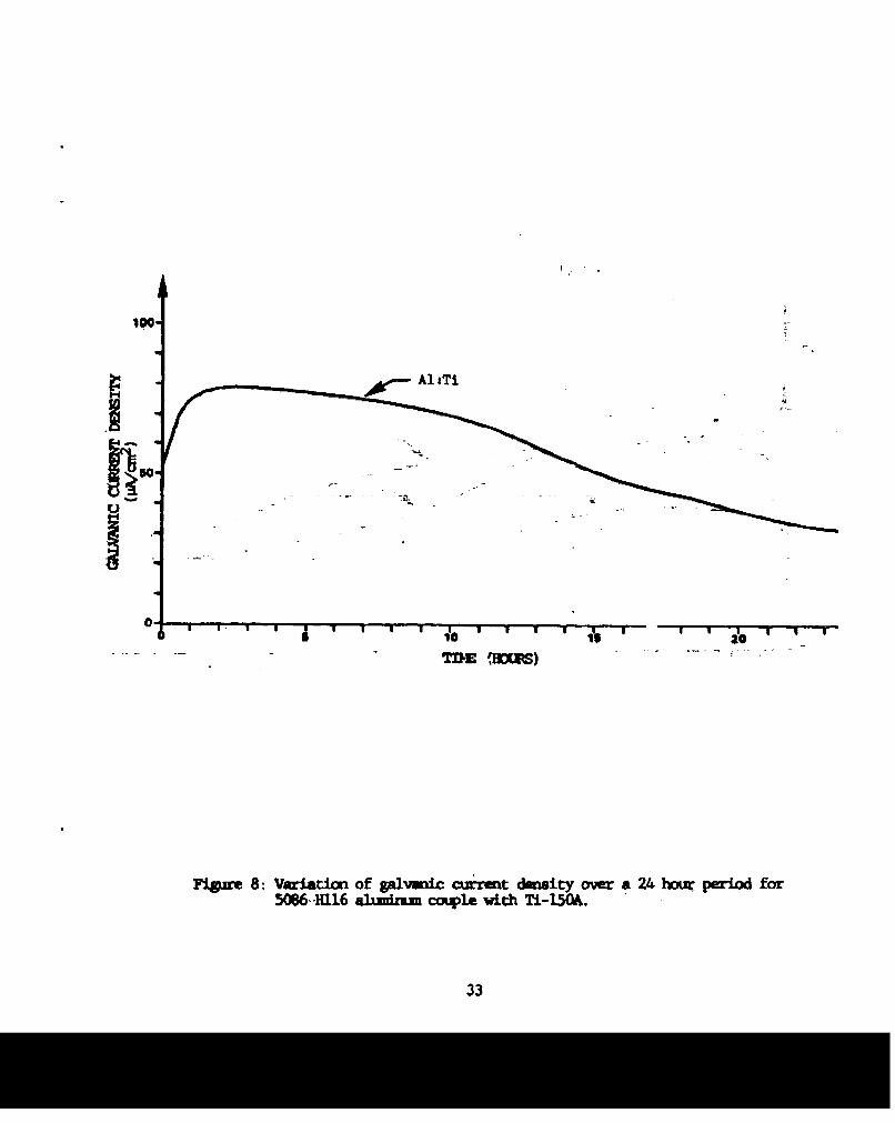
The curves shovm in these figures have certain charactersts in common. For
couples in which the Ti Is the cathodic metal, 1cou starts low (about 45pA/cm2),2upplsrapidly increases to a plateau (about 75PA/cm ), then gradually decreases to about
33pA/cm2 . As mentioned, the initial icouple value is very close to that determined
from the intersection of the Al and Ti polarization curves. The subsequent increase
in current with time from this initial value is considered te be caused by the build
up of an oxide film on the Initially "clean" Ti surface. Since titanium is a reactive
metal, It normally depends on a pr'tective ffim of T1O 2 for corrosion resistance.
The sanding involved in the sample preparation procedure in these experiments removed
the oxide layer, thus making the metal potential more active (closer to that of Al).
The initial rise of current is bel'keved to be associated with passivation of the Ti
surface by oxide laye- growth after iimersion. This causes the potential to become
more noble, and a greater potential difference with the aluminum is obtained. Suchbehavior has been n-otd by Pettibone and Vne2r,%0 1 by .. , % r, d,.G,,. (20) who report that 4he-cu- ,,-,'ntial of
Ti changes from -O.8V when first immersed to -O.lV "after a matter of ininutes" dut
to the development of a protective oxide coating.
The sharp initial rise in current density shown by couples involving Ti was in
contrast to the behavior of couples with brass or steel. The galvanic current for
brass-coupled aluminum samples typically started relatively high (about lOOiA/cm )
(again, as predicted by the polarization curves), decreased rapidly to about 70A/cAi
and then showed a gradual decrease to about 30,A/cm2 after twenty-four hours. Couples
with steel did not start as high (about 60PA/cm 2) and after an initia'i decrease
dropped gradually to about 30uA/cm 2 after twenty-four hours. The initial drop in
current exhibited by couples with steel or brass can probably be attributed to the
initial formation of corrosion product on the Al anode.
13
Once past the initial transient period (of approximately one hour duration)
the current density vs. time curves for various couples maintain the same relative
position with the current densities being ordered from high to low as: Ti/Al,
brass/Al, steel/Al. It is interesting to note that this ordering is consistent
with that which would be predicted using the traditional criteria of position on
the galyanic series.
To calculate the 3verage vflues of galvanic current density for each curve a
simple numerical integration scheme was used, by computing the area under each curve
ana liyiding by the total time. The calculated average icouple values are shown in
Table 11.
TABLE II
Average Galvanic Current Density (vA/cm2)
Temper of Al Anode
Cathode H32 H116 H117
Ti-150A 60 60 57
60/40 Naval Brass 51 50 52
1040 Steel 37 40 38
The data in Table II is quite consistent, with the average galvanic current density
being higher for more noble cathodic metals. Once again, the observation is that the
corrosion rate of the coupled Al alloy can be ordered from high to low as: Ti/Al,
brass/Al, steel/Al. In these experiments, the galvanic corrosion rate of the 5086aluminum alloy was not observed to be affect by temper condition. It was observed
that at the end of the twenty-four hour test period the current density for all couplesare converging to a level of about 30pA/cm2 . The gradual decrease toward this value
is probably caused by a stabilization of the corrosion product accumulation process on
the Al anode. In terms of the polarization curves, one can speculate that the slopeof the anodic Al crmrosion curve is increasing, and is the major determinant of the
observed decay of Icouple with time. These ideas regarding anodic corrosion product
formation were explored further through macroscopic and microscopic examination of
coupled samples, sorm of which were immersed for much longer periods.
14
3. Morphology and Distribution of Corrosion Products on Proximate Galvaic Co~gies
a. Mor haloy and Distribution of Precipitate Formationson Cathodic Members of Couples
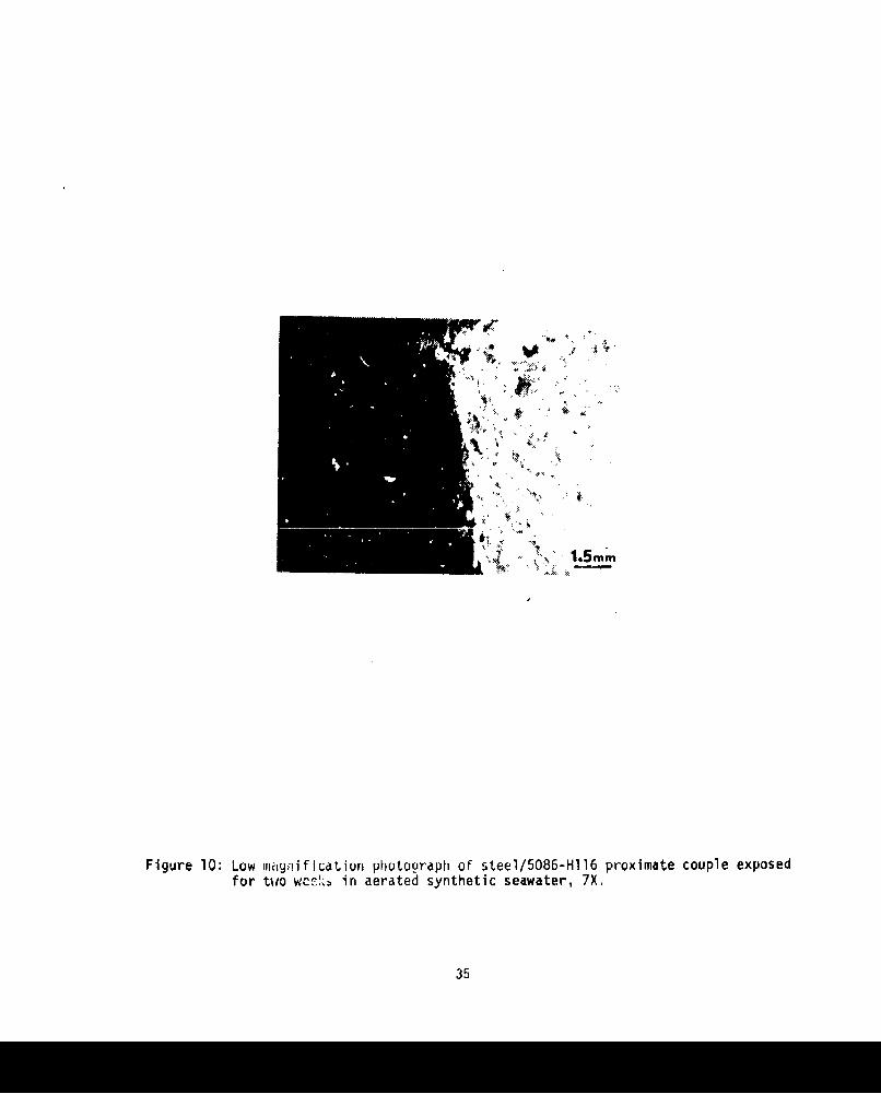
Macroscopically, most of the cathodic members of the coupled samples appeared
to have little precipitate formation on their surfaces. Figure 10 is a macrophoto-graph taken with a polaroid camera attached to a 'ow power light microscope and is
typical of the photographic records made of the physically coupled sa.ples Ofterdrying. These photographs and the SEM photographs included in this work are all
oriented on the pages in the same way that they were hung in the water; the top of
the photo represent the top of the samples as they were exposed; in photographs
presenting a vertical couple Interface, the Al 's on the right side in the photo.
Figure 10 represents a couple exposed fnr two weeks; the cathodic member shows only
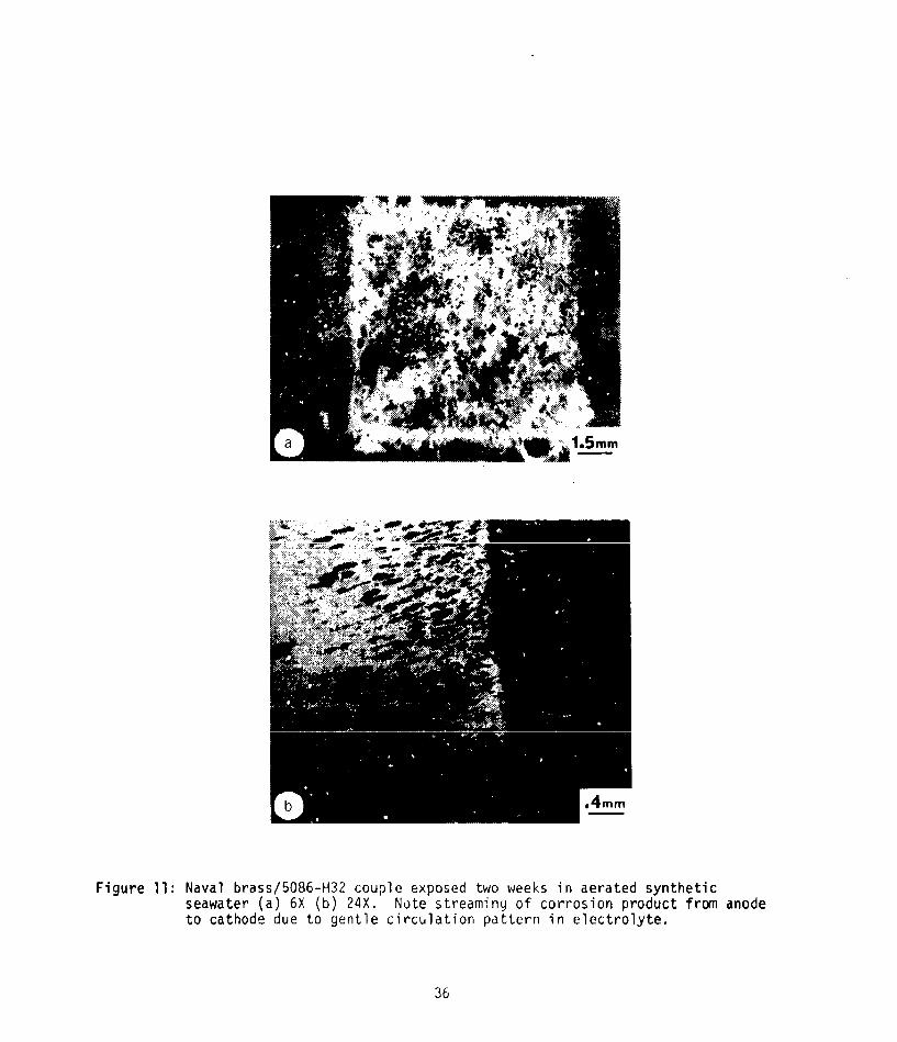
small amounts cf precipitate deposit. Another typical sample is shown in Figure 11
for a two day exposure. There is an accumulation of precipitate on the cathode that
seemE to be streaming from the vicinity of the anode/cathode joint, as seen more
clearly in Figure llb, a higher magnification SEM view of the interface area. The
observed directionality evident in the precipitate distribution is due to the gentle
circulation pattern in the beaker, and indicates that the precipitate is corrosion
product from the Al anode which has been deposited on the cathode.
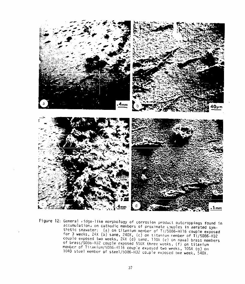
Higher magnification examination of the caii,,Jic accumulation of precipitate
on many samples showed that there are some general characteristics of deposit mor-
phology on the cathodic areas, as illustrated in Figure 12. An extended, ridele-likeformation was the general morphology observed (Figure 12), along with a more complete
base layer covering the cathodic surface (Figure 13). Details of the base layer,
which was present on all cathodic samples, were observable at higher magnifiCation,
where it is seen to consist of an array of very fine crystallites "rgure 13).
Analysis (by energy-dispersive X-ray spectroscopy) of the cathode-located ridge-like
fomations and the base layers showed that these are both aluminum-based compounds.
Therefore It is obvious that these cathode-located products have their origin In
aiodic dissolution processes. The mechanism by which they form and are transported
to the cathodic surfaces is not completely clear at this time. Also, because uf the
small size of the samples used in this work, there was no indication of the distance
over which this coverage might extend. The observation 6f aluminum-based compounds
15
u LUUjJ1iU LdLHUU1 uri6yeb way eariier reporea Oy Feeiean ano rerKIns %9) inwork on the marine corroslon of aluminum: steel explosively bonded Joints.
Another interestirg structure observed on cathodic surfaces, which will bedescribed as "ckrn husk" firmations, is shown in Figure 14. Unlike the featuresmentioned earlier, these fiatures were found on only a few of the samples; analysisof these features using the energy-dispersive X-ray analyzer (Figure 14cd) reveals
that they are a calcium compound, devoid of Al. However, the surface of the metalupon which they stood is co~ered with an Al compound.
These observations c~nfitrm the existence of extensive produ.t and precipitateformations on the cathodic mnmbers of galvanic couples after seawater exposures.These structures can insulate the cathode and thereby reduce the net galvanic effect.
The effect on the anodic memb!r would be to lower the galvanically induced corrosionrate, as indicated by the galvanic current density measurements presented earlier.
Note that none of the observed structures represent artifacts, such as sea saltsdeposited after evaporation, a~s trials with the rinse and drying procedure haveproved. In order to further investigate the effects of corrosion-related productstructures, the corrosion products and associated damage to the Al alloy anodicmembers of couples were also studied.
b. Morphology and Distribution of Corrosion Products on Aluminum AlloyAnodic Members of CoupesMacroscopically, the morphology of the corrosion product on the Al anodic
renbers of couples typically appeared as . white product with no distinct form, asseen in Figure 15; this is undoubtedly an accumulation consisting principally ofvarious forms of hydrated A1203. Examination usin SEM 3head (at relatively luw
nAgnification) that the structure of the corrosion product formed on the Al variesfrom a c...ewhat unevenly distributed structure (as shown in Figures 16a and 16c) toa more compact structure (as shown in Figure 16e).
ft__ h~ r magnificatlon the product, whether non-uniform or compact, has a
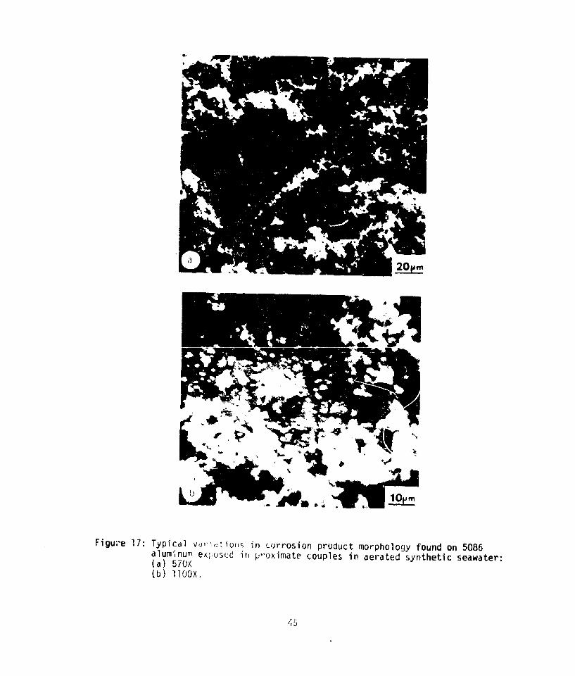
white "snow-like" structure (Figures 16b and 16d). Morphological differences be-tween individual deposits are evident. For example, in Figure 17a the depositsappear to be light and resemble the appearance of dry cold snow while the depositsshown in Figure 17b exhibit a more "globule"-like appearance much like wet snow.These morpholgoical differences may arise due to slight differences in the dryingprocess and is probably not related to any particular variable of the corrosionexposure. These SEM-levwl observations of Al corrosion product morphology are
similar to those reported by previous researchers. Wright (21) observed similar"snow-like" morphologies for corrosion products on Al sacrificial anodes. Some
other examples of corrosion product morphologies observed in this study are shownin Figure 18.
16
Also shown in these figures is a base layer which seems to almost completely
cover the anodic Al. This structure can be seen in Figure l8b in the upper right.
The structure is quite thin, since one can still observe the original sanding marks
on the base metal, to whih the film conforms. At high magnification, this base
layer is seen to have the same structural morphology as the base layer found on the
cathodic surfaces (e.g. Figure 13) Keelean and Perkins (9) observed the presence of
a similar coating.
These observations of corrosion product formations and coatings of the Al
anode, together with the observed coatings on the cathodic metals, help to explain
the previously-presented variations in galvanic current density with time. From
these combined results certain conclusions regarding the galvanic corrosion processes
of these bimetallic couples in seawater can be deduced. As previously described,
the plots of current density versus time indicate that as the immersion time increasec
the current density curves converged to a level of about 30pA/cM , and it was post-
ulated that this must be due to the formation of insulating layers on the electrode
surfaces. It is nop; confirmed that layers form and cover both the anodic and cathodic
surfaces, at least in proximate couples. As a result of these observations, the
question arise!. v,hether, due to the extent of these coatings, the galvenic effect
becomes small, so that local corrosion modes on the individual metals, such as crevice
corrosion and pitting, may flourish. In order to study this further, the distributior
of corrosion products and dissolution damage on the anodic surfaces, was carefully
examined as a function of time.
Visual examination of all samples taken as a group produced some general
observations on corrosion product distribution. Corrosion product accumulations on
the Al member of the couple tendea to be greater with longer exposure times, as
expected. Also, for exposures up to one week, couples containing H32 generally
showed greater corrosion product accumulation than couples containing H116 or H117;
this difference was nv longer obvious when the exposure was extended to two weeks
or greater, and was the only observation of a temper effect noted in this study.
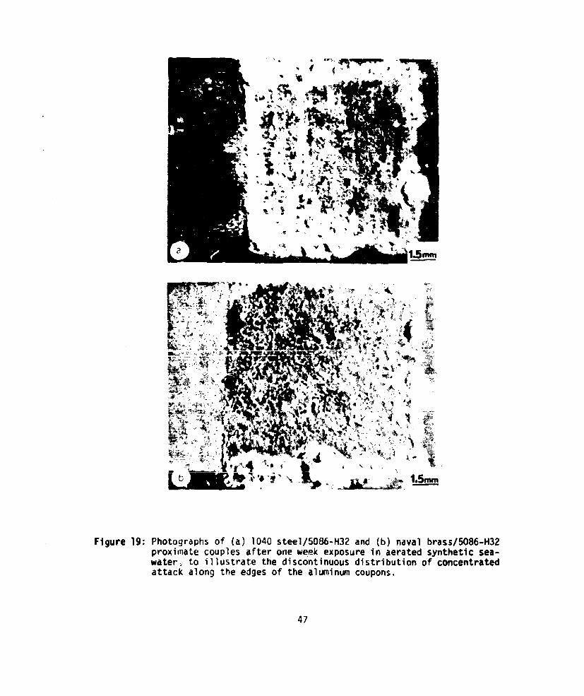
Figure 19 illustrates features which were present on many samples. Typically,
the edges of the exposed planar area of the A'l were covered by a heavier accumula-
tion of corrosion product, in contrast to the relatively uniform distribution over
the central surface area of the sample. The cathode:anude interface was sometimes
but not always covered by a heavier dist, ibution; an intsrfacial outcropping (e.g.
Figure 19a) was observed on about twenty five percent of the samples exposed. Other
samples showed no :pecial accentuation of corrosion product coverage at the cathode:
anode interface (e.g. Fig. 19b). These variations carnot be correlated with any
particular variable, such as immersion time, cathodic metal or temper of the Al alloy
17
The interface regions of proximate couples showed a number of interesting
features. Of particular interest was what could be called a "corridor" on the Al,
Immediately adjacent to the build up of corrosion products at the interface, as
shown in Figure 20. This "corridor, ,een in the top middle of Figure 20a shows
much less corrosion product on the A; immediately adjacent to the interface. Figure
20b shows a higher magnification view of the area under discussion. Areas such as
this were prevalent on almost all samples, and were always most pronouioced adjacent
to heavy accumulations of corrosion product.
In these experiments, the cathode:anode interface typically experienced
less accumulation of corrosion products than at the plastic mount:aluminum inter-
faces. An attempt to quantify this observation was made. The (one) galvanic inter-
face and (three) plastic:Al interfaces of each aluminum coupon were rated as to
light, moderate, or heavy accumulations of corrosion product. These ratings were
then weighted, added, and averaged. This was done several times. The results always
showed that the accumulation for the galvanic joints was slightly less than a moderate
build up and the average for the Al plastic edges was slightly less than half way
between a moderate and a heavy build up.
The results seem at first to be contrary to expectations based on traditional
treatment of interactions in galvanic couples. It might be expected that the quan-
tity of corrosion product build up and dissolution damage would be concentrated
particularly at the cathode: anode interface and decrease smoothly as some function
of distance (potential) away from that interface. This does not occur, largely due
to the small size of the proximate coupons and the high throwing power (ionic
conductivity) in these galvanic cells, so that the potential distribution is spread
out.The observed feature of a degree of increased attack at the plastic:Al inter-
faces occurred because the specimen design enployed could not avoid some finite
elevation difference at these interfaces (see Fig. 3), so that some concentration of
electr-ode current occurs at these locations. Some of the results reported in the
next section, for samples cleaned of corrosion products, will support these explana-
tions of sample mount edge effects. It should be noted that these edge effects
were not so great as to confuse observations of general corrosion product form and
distribution over the menoers of the galvanic couples.
c. Distribution of Dissolution Damage
After cleaning corrosion products from the samples, correlations between
corrosive attack and distribution of corrosion product were obvious. If an area
- ~ ~ ~ ~ ~ ~ atl .- F'.-m,~I~ j .Ium I .DtUUA, LIIMIt UILt f 96IC0UI1fly, 0 U ~ .YU
other form of concentrated corrosive attack was always observed beneath that
18
position. An example of this is shown in Figure 21. The macrophotograph (Figure
21a) shows a large accumulation of corrosion product at the top along the cathode:
anode interface and a relative lack of corrosion product along the lower portion of
the interface. Figures 21b and c show the damage incurred in those two areas,
respectively. The base metal under the location of extensive corrosion product ac-
cumulation was severely attacked, whereas the region where there was less product
accumulation had been only lightly attacked. This correspondence between accumula-
tion and damage was also evident at locations along plastic:Al interfaces, and on
the central areas of the exposed faces of 'he anode samples.
As previously shown, localized dissolution tends to occur at cathode:anode
interfaces, and correlations between the position of concentrated dissolution and
heavy corrosion product accumulations were readily apparent. Additionally, obser-
vations showed that even though a flat, tight metal-to-metal joint was present prior
to immersion, localized attack at the interface rapidly opened up a crevice-like
cavity along the interface; examples (for 2-day exposure) are shown in Figure 22,Variation in the extent of development of this interfacial cavity are associated with
the observed variation in corrosion product accumulations along the joint mentioned
earlier. Figure 23 shows examples of interfacial dissolution distribution after
somewhat longer exposures.
From all these observations, some ideas can be developed which describe the
sequence of events involved in the attack of the galvanically coupled anodic Al.
Upon immersion, the raised edges of the Al at the plastic: Al interfaces and the
cathode: anode interface act as current concentrating sites, due to the non-uniform
geometry and the galvanic potential respectively. This action, together with the
likely presence, or development of, slight crevices at the interfaces provide sites
at which localized corrosion can take place. Since the potentials of the coupled
cathodic metals are more noble than the critical pitting potential of the Al, dis-
solution will tend to start at these areas (and also possibly at other areas where
imperfections exist in the oxide). As the other areas of the Al become more passive
(covered with a protective oxide film) the unfavorable area ratio accelerates cor-
rosion in areas that have started to dissolve. As the cathode and anode of the
bimetallic couples become covered with deposits, and the total galvanic current
decreases, areas which are being attacked most aggressively tend to "rob" current
from immediately adjoining areas~producing the low-corrosion "corridors" observed
next to the locations of highest attack. In effect, these "corridor" regions are
being cathodically-protected by the locally pronounced anodic action. As time goesan the m1.aA .++.,L Mn.. ao h ar.4,..nn...A 1 la-C A'
4eeal .tj
cavities are developed.
19
CONCLUSIONS
The following conclusions have been reached as a direct result of this research.
1. Galvanically induced corrosion of 5086 Al alloy is independent of temper
condition for the time period studied (less than three weeks).
2. The rate of corrosive attack of the 5086 aluminum alloy anodic member of
couples, based on current density measurements, can be ordered from highest
to lowest as Ti/Al, brass/Al, steel/Al (for 24-hour exposure trials).
3. Formation of insulating corrosion products and structures on both cathodic
and anodic members of couples acts to reduce the effect of dissimilar metal
coupling. The primary source of these films is dissolution of the anodic
Al, upon which the Al corrosion product accumulates, or from which it can
migrate to the cathodic member and accumulate. These coverage effects
cause a decrease in galvanic current density with increasing exposure time.
4. Non-uniform development of corrosion products on the Al anodic member of
couples leads to concentration of corrosive attack at localized areas.
This causes severe dissolutio attack to take place, and a cathode/anode
relationship is developed with immediately adjacent areas.
5. Heavy accumulations of corrosion product on Al anodic members of couples
are associated with directly underlying large dissolution cavities.
20
REFERENCES
1. M. Pourbaix, Atlas of Electrochemical Eouilibria in Aqueous Solutions,2nd ed., p. 168-175 tona-tAssociation of Corrosion Engineers, 1974.
2. R.K. Hart, "The Formation of Films on Aluminum Immersed in Water," Trans-actions of the Faraday Sociey, 53(1957) 1020-1027.
3. D.O. Sprowls, "High Strength Aluminum Alloys with Improved Resistance toCorrosion and Stress-Corrosion Cracking", paper presented at the Tri-ServiceCorrosion Conference, Philadelphia, Pennsylvania, 26-28 October 1976.
4. W. Strasburg, "Survey of Corrosion Problems of Destroyer Type Ships," NAVSECtravel report ser 78-6101C, 25 January 1971.
5. T.J. Summerson, "Aluminum Association Task Group Exfoliation and xoress CorrosionTesting of Aluminum Alloys for Boat Stock", paper presented at .,-;-Service Cor-rosion of Military Equipment Conference, Dayton, Ohio, 29-31 October 1974.
6. P. Doig, and J.W. Edington, "The Influence of Solute Depleted Zones on the Stress- Corrosion Susceptibility of Aged Al - 7.2 Mass % Mg and Al - 4.4 Mass % CuAlloys," Proc. Royal Soc. London, 339 (1974) 37-47.
7. C.L. Brooks, "Aluminum - Magnesium Alloys 5086 and 5456- H116," Naval En ineersJournal 82 (August 1970) 29-32.
8. E.J, Czyryca and J.P. Hack, "Corrosion of Aluminum Alloys in Exfoliation -Resistant Tempers Exposed to Marine Environments for Two Years", paperpresented at Tri-Service Corrosion of Military Equipment onference, Dayton,Ohio, 29-3i Oci;ober 1974.
9. G.S. Haynes and R. Baboian, "Reducing Galvanic Corrosion with Transition Metals,"Materials Performance 16(1977) 36-39.
10. M.R. Keelean and A.J. Perkins, "Microscopic Investigation of Interface Corrosionof Steel - Aluminum Explosively Bonded Material Exposed to Periodic Sea WaterSpray", M.S.M.E. Thesis, Naval Postgraduate School, Monterey, CA, 1976.
11. F.L. LaQue, Corrosion Handbook, p. 416, Wiley, 1948.
12. F. Mansfeld and jV. Kenkel, "Laboratory Studies of Aluminum Alloys," Galvarand Pitting Corrosion - Field and Laboratory Studies, ASTM cTP 576, pp -7T
13. R. Baboian, "Investigation of Galvanically - Induced Localized Corrosion,'Localized Corrosion - Cause of Metal Failure, ASTM STP 516, pp. 145-163,American Society for Testing-and Maeial,972.
14. R. Baboian, "Electrochemical Techniques for Predicting Galvanic Corrosion,"Galvanic anc Pitting Corrosion - Field and Laboratory Studies, ASTM STP 576,pp. 5-19, 19,o.
15. National Association of Corrosion Engineers, NACE Standard TM-0l-69, "TestMethod: Laboratory Corrosion Testing of Metals for the Process Industries",1969.
21

16. U.K. Kester, I.W. Duedall, D.N. Coners, and R t'1 Pytokowicz. 'Preparation ofArtificial Seawater," Limnology and Oceanography, (12)(1967) 176-178.
17. F. Mansfeld and J.V. Kenkel,"Electrochemical Toctina of Galvanic Corrosio',paper presented at Tni-Service Corrosion Or Military Equipment Conference,Dayton, Ohio, 29-31 October 1974.
18. F. Ma'ifeld and J.V. Kenkel, "Laboratory Studies of Galvanic Corrosion, 1.
Two-Metal Couples, Corrosion, 31 (1975) 298-302.
19. F.L. LaQue, Marine Corrosion, pp. 194-195, Wiley, 1976.
20. J.S. Pettibone and R.L. Kane, "Titanium". Corrosion Resistance of Metals and-Aly,2nd ed., edited by LaQue, F.L. and Copson, H.R., pp. 647-648, Rein id,'
21. P.W. Wright,"A Scanning Electron Microscope Study of the Cnrrosion of Sacrificial'Hull Anodes unner Simulated Ship Service Condition', M.S.M.E thesis, Naval Post-graduate b..rooI, Monterey, CA, 1976.
22
LIST OF FIGURES
Figure 1: Microstructures of 5086 aluminum alloys used in these studies,all 200x, Kellers etch (a) 5086-H32, (b) 5086-HI16, (c) 5086-H117.
Figure 2: (a) Experimental equipment used for exposure of galvanic couples(b) Mounting equipment used to form proximate galvanic couples
Shown are torque wrench, sample coupons, mounting ring, andfinal mounted couple.
Figure 3: (a) Initial condition of bimetallic interface in proximate bimetalliccouples, 550x. (b) Initial condition of metal: plastic interfacesof mounted samples, 240x.
Figure 4: Potentiodynamic polarization curves for 5086 aluminum and 1040 steelin aerated synthetic seawater.
Figure 5: Potentiodynamic polarization curves for 5086 aluminum and naval brassin aerated synthetic seawater.
Figure 6: Potentiodynamic polarization curves for 5086 aluminum and Ti-150Atitanium in aerated synthetic seawater.
Figure 7: Variation of galvanic current density over a 24 hour period for5086-H32 aluminum couples with 1040 steel, naval brass, and Ti-150A.
Figure 8: Variation of galvanic current density over a 24 hour period for5086-H116 aluminu couple with Ti-150A.
Figure 9: Variation of galvanic current density over a 24 hour period for 5086-H117couples with 1040 steel, naval brass, and Ti-lSOA.
Figure 10: Low magnification photograph of steel/5086-H116 proximate couple exposedfor two weeks in aerated synthetic seawater, 7X.
Figure 11; Naval brass/5086-H32 couple exposed two weeks in aerated syntheticseawater (a) 6X (b) 24X. Note streaming of corrosion product from anodeto cathode due to gentle circulation pattern in electrolyte.
Figure 12: General ridge-like morphology of corrosion product outcroppings found inaccumulations on cathodic members of proximate couples in aerated syn-thetic seawater: (a) on titanium member of Ti/5086-4116 couple exposedfor 3 weeks, 24X (b) same, 240X, (c) on titanium member of Ti/5086-H32couple exposed two weeks, 24X (d) same, llOX (e) on naval brass membersof brass/5086-H32 couple exposed 550X three weeks, (f) on titaniummember of Titanium/5086-H116 couple exposed two weeks, 105X (g) on1040 steel member of stoel/5086-H32 couple exposed one week, 540X.
Figure 13: Details of the structural morphology of the continuous base layercovering the cathodic members of proximate couples, in this caseon the 1040 steel member of a steel/5086-H32 couple exposed for threeweeks in aerated synthetic seawater: (a) lI5OX (b) 2300X. The baselayer is observed to be made up of a regularly arranged array of veryfine crystallites.
23

Figure 14: Precipitate formations occasionally found on cathodic meribers ofproximate couples, shown here for brass/5086-H32 couples in aeratedsynthetic seawater: (a) exposed two weeks, 230X, (b) exposed eightweeks, l1OX, (c) same, 550X, (d) calcium x-ray distribution imageof same area.
Figure 15: Low-magnification photograph of naval brass/5086-H32 proximate coupleexposed for one week In aerated synthetic seawater, 7X.
Figure 16: Typical corrosion product accumulations on 5086-HI16 aluminum inproximate couples exposed in aerated synthetic seawater (a) 5086-HI16coupled to TI-150A, exposed three weeks, 23X, (b) same, 1l50X, (c)5086-HI16, coupled to 1040 steel, exposed one week, 150X, (d) same,1150X, (e) 5086-H116 coupled to Ti-150A, exposed two weeks, 55X.
Figure 17: Typical variations in corrosion product morphology found on 5086aluminum exposed in proximate couples in aerated synthetic seawater:(a) 570X(b) 110OX.
Figure 18: Examples of various corrosion product morphologies observed on 5086aluminum exposed in proximate couples in aerated synthetic seawater.(a) 5086-H32, coupled with 1040 steel, exposed one week, 2200X,(b) 5086-HI16, coupled with 1040 steel, exposed three weeks, 1100X,(c) 5086-H32, coupled with 1040 steel, exposed three weeks, 540X,(d) 5086-H32, coupled to naval brass, exposed one week, 575X.
Figure 19: Photographs of () 1040 steel/5086-H32 and (b) naval brass/5086-H32proximate couples after one week exposure in aerated synthetic sea-water, to illustrate the discontinuous distribution of concentratedattack along the edges of the aluminum coupons.
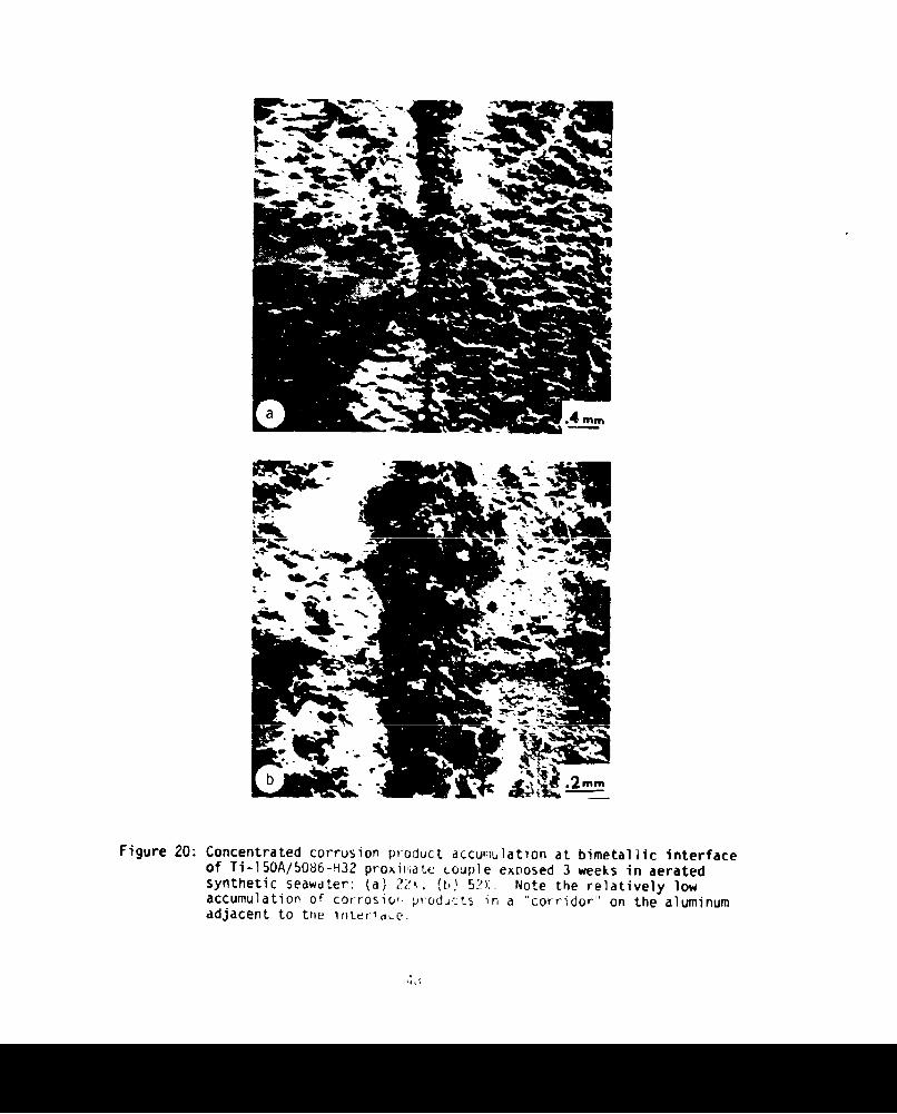
Figure 20: Concentrated corrosion product accumulation at bimetallic interfaceof Ti-150A/5086-H32 proximate couple exposed 3 weeks in aeratedsynthetic seawater: (a) 22X, (b) 52X. Note the relatively lowaccumulation of corrosion products in a "corridor" on the aluminumadjacent to the interface.
Figure 21: Illustration of correlation of corrosion product distribution anddissolution pattern, for Ti-150A/.5086-H3? proximate couple exposedtwo days in aerated synthetic seawater: (a) low magnification photo-graph of couple, showing distribution of corrosion products alongbimetallic interface; (b) dissolution cavity found in the aluminumafter ultrasonic cleaning, located under the heavy corrosion productoutcropping seen in (a) at the top along the interface, 1OOX; (c) nodissolution cavity is found further down the same interface, 550X.
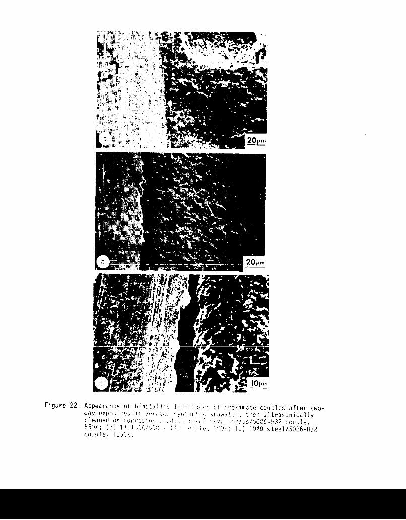
Figure 22: Appearance of bimetallic interfaces of proximate couples after two-day exposures in aerated synthetic seawater, then ultrasonicallycleaned of corrosion products: (a) naval brass/5086-H32 couple,550X; (b) Ti-150A/5086-HI16 couple, 600X; (c) 1040 steel/5086-H32couple, 1050X.
24
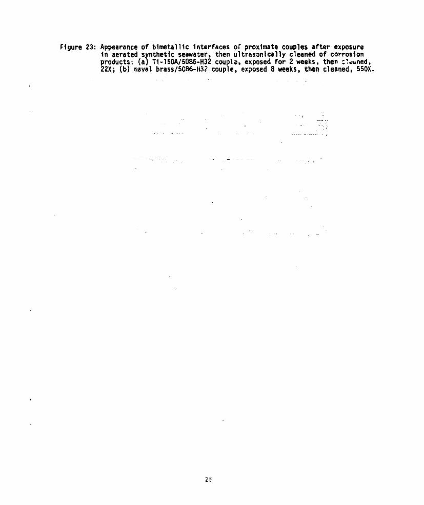
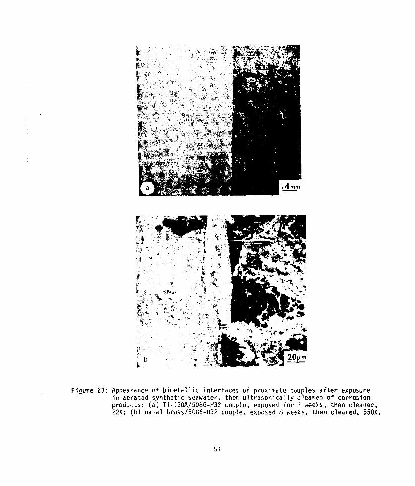
Figure 23: Appearance of bimetallic interfaces of proximate couples after exposureIn aerated synthetic seawater, then ultrasonically cleaned of corrosionproducts: (a) Ti-150A/5086-H32 couple, exposed for 2 weeks, then :',ned,22X; (b) naval brass/5086-H32 couple, exposed 8 weeks, then cleaned, 550X.
2F
r..A
r AT
'm 4.
L > -
9E-4v-.4J
U)
S*~~#~~%L 0i141 -2
2f,,

its"
b
Figure 2: (a) Experimental equipment used for exposure of galvanic couplesb)Mounting equipment used to formr proximate galvanic couples
Shown are torque wrench, sample coupons, mounting ring, anGfinal mounted couple.
27
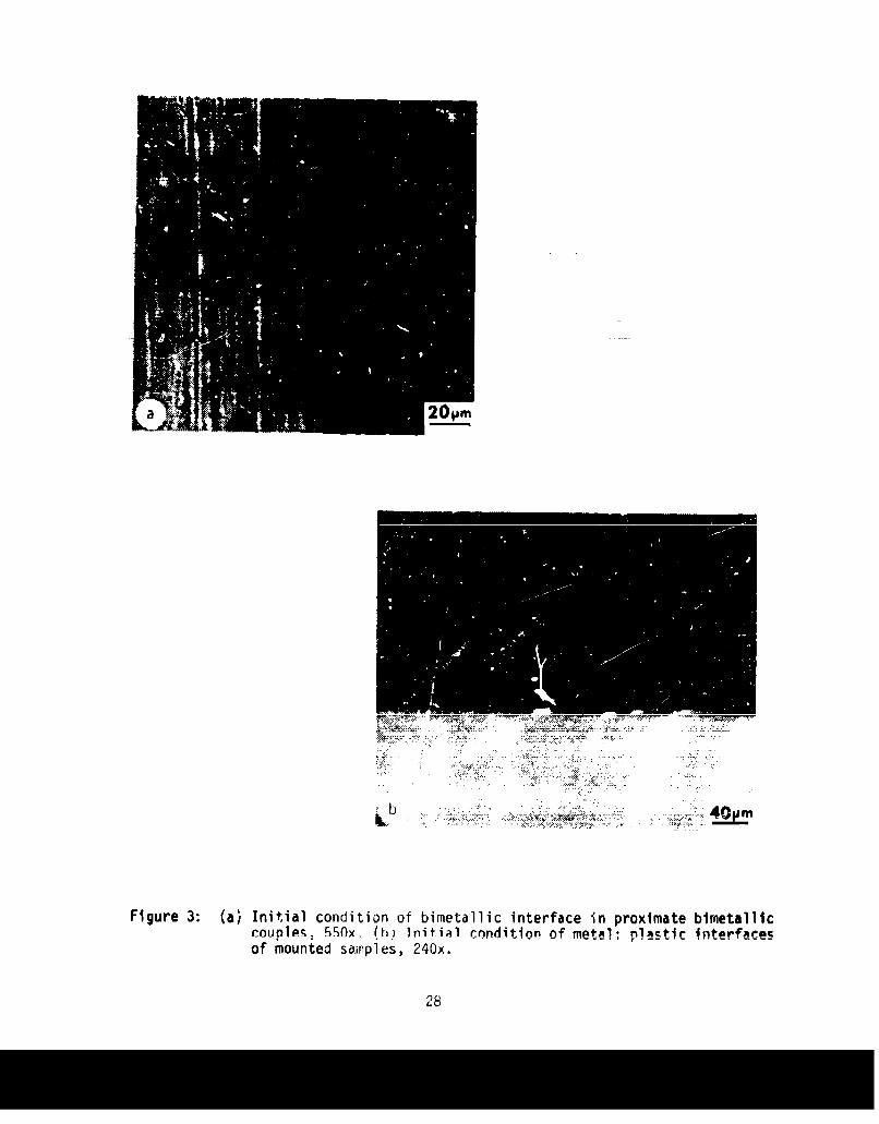
Figure 3: (a) Initial condition of bimretallic interface in proximate bimetalliccounles. 5Ox. (h) Initial condition of metal- nlactiC in~terfacesof mounted samnples, 240x.
28
-0.4-
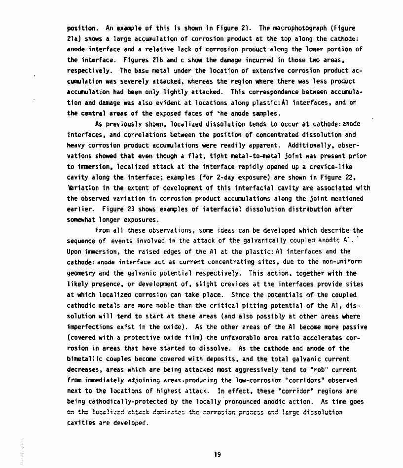
lo n, aer te ye ti) seawter
Ecoup29
-0.2
-04-
10100 21000
Figure 5: Potentiodynaic polarization curves for 5086 aluminum and naval brassin aerated synthetic seawater.
30
-0.2,'
--Eor (Ti)
Ti
-0.6-
J 'Corr
1couple
-1.4,10 10O 1000
Figure 6: Potentiodynamic polarization curves for 5086 aluminum and TI-ISAtitanium in aerated synthetic seawater.
31

100
AliSteel
T V0 15 3
_ ~TIM ([JJI) __
Figure 7: Variation of galvanic current density over a 24 hour period for5086-H32 aluminum, couples with 1040 steel, naval brass, and Ti-lSOA.
1001
.Ie- Al I I
FAIp~e 8: Variationr of galvsnic curent density over a 24 hour period for506,H16 luirwmuz couple with Ti-150A.
33

100
TIM (OR)
Figure 9: Variation of galvanic current density over a 24 hour period for 5086-H117couples with 1040 steel, naval brass, and TiISO.
34
1.5m r
Figure 10: Low miignification photograph of steel/5086-H116 proximate couple exposedfor tw~o wcc!.'z in aerated synthetic seawater, 7X.
35
a 1.mm
Figure 11: Naval brass/5086-H32 couple exposed two weeks in aerated syntheticseawater (a) 6X (b) 24X. Note streaminy of corrosion product from anodeto cathode due to gentle circulation pattern in electrolyte.
36
-C f.
A!!0, w.aI
.- r
Ole
~l
L a . 4 m ~ 1WW 40.
'~~'Nr zL4 m
rigure 12: Gneral ridgelike morpholgy of corro ipoutotropnsfudi
Figur 12:enerlationslik onca hocmeger of roimat prdctoutes ping aerate synthetic seawater; (a) on titanium member of Ti/5086-H-116 couple exposedfor 3 weeks, 24X (b) same, 240X. (c) on titaniui-i mber of Ti/5086-1132couple exposed two weeks, 24X (d) Salle, 11OX (e) on naval brass membersof brass/5086-H32 couple exposed 55X three weeks, Mf on titaniummember of Titaniurn/50816-HI16 couple exposed two weeks, 105X (g) on1040 steel member of steel/5086-F!32 couple exposed one week, 0X
37

t
-77
e IM
20 m
Figure 12: General ridge-like morphology of corrosion product outcroppings found inaccumulations on cathodic members of proximate couples in aerated syn-thetic seawater: (a) on titaniumn member of Ti/5086-H116 couple exposedfor 3 weeks, 24X (b) same, 240X, (c) on titanium member of Ti/5086-H32couple exposed two weeks, 24X (d) same, 11OX (e) on naval brass membersof brass/5086-1132 cou;1ec exposed 5 JX three weeks, (f) on titaniummember of Titarium/5Q86-11116 couple exposed two weeks, 105X (g) on1040 steel memiber of st'e1/5086-fl32 couple exposed one week, 540X.
~79 Y
!.4
L ftft'': ', : ; :: ", : ':. -r U , .tS o t
Figure 13: Details of the structural morphology of the continuous base layercovering the cathodic members of proximate couples, in this caseon the 1040 steel member of a steel/5086-1132 couple exposed for threeweeks in aerated syrthetic seawater: (a) 1150X (b) 2300X. The baselayer is observed to be made up of a regularly arranged array of veryfine crystall ites.
39
Figure 14: Precipitate formratiuris oc -una I l~y f ound on cathodic members ofproximate couples, showr, here for bras5/5086-H32 couples in aeratedsynthetic seaWdtet': (a) expoted two weeks, 230X, (b) exposed eightweeks, 1lOX, ((c) sdine, YiOX. (d) LilOiJjfl x-ray distribution imageof same area.
Figure 14: Precipitate fori'ationu C)CcdSionally found on cithodlic members ofproximate cuuple, , shown here for brass/5086-H32 couples in aeratedsynthetic seawdjtec.: (a) expused LWO weeks, 230X, (b) exposed eightweeks, liOX, (L) ba'~ 5OY,, (d) calcium x-ray distribution imageof saine ared.
44
14
I~dd
Figure 16: Typical corrosion product accumulations on 5086-.H116 aluminum inproximate COuJPIQes exposed in aerated synthetic seawater (a) 5086-H116coupled to Ti-l50A, exposed three weeks, 23X, (b) same, 1150X, (c)5086-Hub6, coupled to 1040 steel, exposed one week, 15OX, (d) same,ilSOX, (e) 50816-111l6 coupled to TI-150A, exposed two weeks, 55X.
it, 1
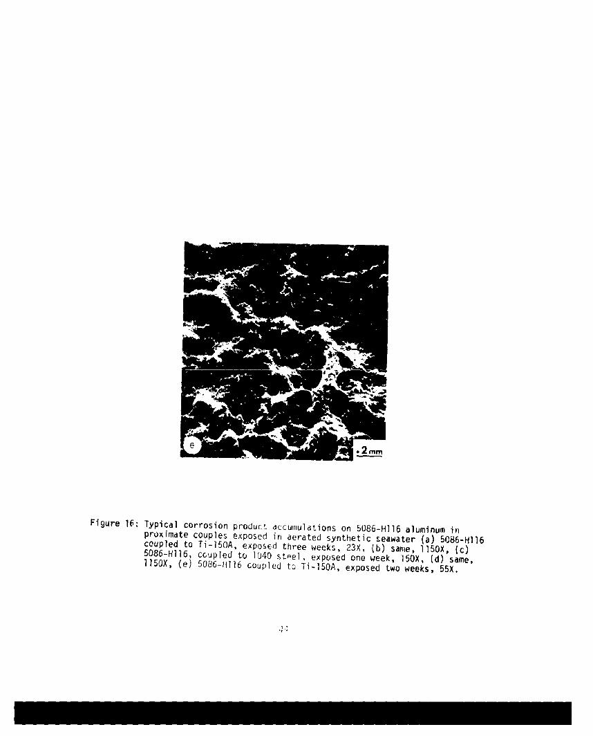
Figure W:Typical corrosion product accumulations on 5086-H116 aluminum inpruximate couples exposed in aerated synthetic seawater (a) 50,86-H116coupled to Ti-150A, exposEd three weeks, 23X, (b) same. i15OX, (c)5086-HI16, ccupled to 1040 steel, exposed one week, 150X, (d) same,1150X, (e) 5086-11116 coupled to Ti-1SQA, exposed two weeks, 55X.
Ja
L %
Figure 17: Typical vru c.ioQs in corrosion product morphology found on 5086alumnum exposoed in p-oximate couples in aerated synthetic seawater:(a) 570X(b) lloOX.
45

4j-
Fiur 1:Exmpeso vriu crrsinprdut nrpolgesobere oA58
aluinu eposd n pox Meculsiaetdsyhtcsewer(a)508-H3, cupld wth 040stel, xpoed ne eek 2?0X
(b)~~~~ ~~ 506H1,cule ih14 tel xoe hrewelQ
(c 08-32 ould ih 00 tel xpsd heewek,54XAd.5- 32 cope7o4vl rsepsd n ek 7X
U4
of4-
44
4,01.4r4
Ai VA
r&~<'), A4 % 42t
,~A .4;
~ ~
Figure 19: Photographs of (a) 1040 steel/5086-H32 and (b) naval brass/5086-H32proximate couples after one we ek exposure in aerated synthetic sea-water, to illustrate the discontinuous distribution of concentratedattack along the edges of the aluminum coupons.
47
Fiur 2: ocetrte orosonpodctdculiiaI~latbiet~c ntrfc
of T-15A/$06-H2 prxilte cupl expsed3 weks n aeate
Figre20:Cocumulateodo corrso podts CP)iaI a t r ir ontheii ain umac
adjacent to ttie iriteridoC'.

+
a~ 1.5mm
A~
C _____
Figure 21: Illustration of correlation of corrosion product distribution anddissolution pattern, for Ti-150A/5086-H32 proximate couple exposedtwo ddys in aerated synthetic seawater: (a) low magnification photo-graph of COUDle, showing distribvi. on of corrosion produrts alongbimetallic interface; (b) d-issolution cavity found in t1 aluminumafter ultrasonic cleoning, located under the heavy corrosion producto Lcropping seen in (a) at theU top alo.ig the interface, 1OOX; (c) nodissolution cjvity is found furt~ier down the same interface, 550X.
49
15;.m
Figure 22: Appearance o f Uie', Lu 1 1 Lt I c , roxiilate couples after two-day exposu re S ill,~j1: ItIt ewti then ul trasonicallycileaned ot corru'~i o. i d v "j hra s/ 5086-V132 couple,550X; (0K li1i/\KO weQ~' (C) ]WO1 steel/5086-H32couple, 15t
0 F =
S A
b 20v__m
Figure 23: Appearance of bimetallic interfaces of proximrate couples after exposurein aerated synthet-ic seawater, then ultrasonically cleaned of corrosionproducts: (a) Ti-15OA/5086-H32 couple, exposed for 2 weeks, then cleaned,22X; (b) na'al brass/5086-H32 couple, exposed 8 weeks, theni cleaned, 550X.
j,
INITIAL DISTRIBITION LIST
No. Copies
1. Defense Documetation Center 2Cameron StationAlexandria, Virginia 22314
2. Library, Code 0142 2
Naval Postgraduate SchoolMonterey, California 93940
3. Department Chairman, Code 69 2Department of Mechanical EngineeringNaval Postgraduate School
Monterey, California 93940
4. Naval Research Laboratory 1
Washington, D. C. 20390Code 2627
5. Naval Air Propulsion 1Test CenterTrenton, NJ 08628Attn: Library
6. Office of Naval Research 1
Department of the Navy (Attn-Code 471)800 N. Quincy Street
Arlington, VA 22217
7. Naval Air Development Center 1
Code 302Warminster, PA 18974
Attn: Mr. F. S. Williams
8. Naval Construction Battalion
Civil Engineering LaboratoryPort Hueneme, CA 93043Attn: Materials Division
9. Office of Naval Research 1800 N. Quincy Street
Arlington, VA 22217Attn: Code 102
10. Naval Electronics Lab. Center 1
San Diego, CA 92152Attn: Electron Materials
Sciences Division
11. Naval Missile Center 1Materials Consultant
Point Mugu, CA 93041
12. Office of Naval Research800 N. Quincy StreetArlington, VA 22217Attn: Code 470
13. Commanding Officer 1Naval Surface Weapons CenterWhite Oak Laboratory -
Silver Spring, MD 20910
14. David W. Taylor --
Naval Ship R & D CenterMaterials DepartmentAnnapolis, MD 21402
15. Commanding Officer 1Office of Naval Research --
Branch Office495 Summer StreetBoston, MA 02710-
16. Naval Undersea CenterSan Diego, CA 92132Attn: Library
17. Naval Underwater System Center ... < 1Newport, RI 02840Attn: Library
18. Commanding Officer 1Office of Naval ResearchBranch Office536 S. Clark StreetChicago, IL 60605
19. Naval Weapons Center 1China Lake, CA 93555Attn: LibrFry
20. Naval Air Systems Connand 1Washington, D. C. 20360Attn: Code 52031
21. Office of Naval Research 1San Francisco Area Office760 Market Street, Rm 447San Francisco, CA 94102
22. Naval Air Systems Command 1Washington, D. C.Attn: Code 52032
23. Naval Air Systems Command 1Washington, D. C. 20360Attn: Code 320

24. Naval Research Lab.
Washington, DC 20390Attn: Code 6000
25. Naval Sea System CommandWashington, DC 20362Attn: Code 035
26. NASA HeAdquartersWashington, D. C.Attn: Code RRM
27. Naval Research Lab.Washington, DC 20390Attn: Code 6100
28. Naval FacilitiesEngineering CommandAlexandria, VA 22331Attn: Code 03
29. NASALewis Research Center2C111 Brookpark RoadCleveland, Ohio 44135Attn: Library
30. Naval Research Lab.Washington, D.C. 20390Attn: Code 6300
31. Scientific AdvisorCommandant of the Marine CorpsWashington, D. C. 20380Code AX
32. National Bureau of StandardsWashington, DC 20234Attn: Metallurgy Division
Inorganic Mat. Div.
33. Dr. Wa. R. PrindleNational Academy of SciencesNational Research Council2101 Constitution Ave.Washington, DC20418
34. Dr. R. P. Wel, Lehigh Univ.Inst. for Fracture &Solid MechanicsBethlehem, PA 18015
35. Prof. H. G. F, Wilsdo-LUniv. of VirginiaDept. of Mat. ScienceCharlottesville, VA 21903

36. Defense Metals and CeramicsInfo CenterBattelle Mm. Imstitute505 King Ave.
Columbus, Ohio 43201
37. Naval Ship Engr. CenterCTR BG #2 Code 61013700 E-W Highway
Prince George PlazaHyattsville, MD 20782
38. Director, Ordnance Research Lab.
P.O. Box 30State College, PA 16831
39. Army Research OfficeBox CM, Duke StationDurham, NC 27706Attn: Metallurgy & Cer. Div.
40. Army Materials and Mechanics*esearch Center
Watertown, MA 02172Attn: (AMXHR-P)
41. Dir. Applied Physics Lab.University of Washington1013 NE 40th StreetSeattle, WA 98105
42. Metals and Ceramics Div.Oak Ridge Nat'! Lab.P.O. Box XOak Ridge, TN 37380
43. AF/Ofc. of Scientific ResearchBldg. 410 Bolling AF Base
Washington, D. C. 20332Attn: Chem. Sci. DirectorateElectronics & S. S. Sci. Director
44. Los Alamos Scientific LabP.O. Box 1663Los Alamos, NM 87544Attn: Report Librarian
45. AF Materials Lab. (LA)Wright-Patterson AFBaseDayton, Ohio 45433
46. Argonne National Lab.Metallurgy DivisionP.O. Box 229Lemont, IL 60439

47. Dr. J. A. S. GreenMartin Marietta Corp.i450 S. Rolling RoadBaltimore, MD 21227
48, Dr. T. R. BeckElectrochemical Tech. Corp.19035 31st Ave. NESeattle, WA 98125
49. Prof. R. H. HeidersbachUniversity of Rhode IslandDepartment of Ocean Engr.Kingston, RI 02881
-50. Professor I. M. BernsteinCarnegie-Mellot Univ.Schenley ParkPittsburgh, PA 15213
51. Professor H. K. Birnbaum .Univ. of IllinoisDept. of MetallurgyUrbana, IL 61801
52. Prof. J. P. HirthOhio State UniversityMetallurgical Engineer ingColumbus, OH 43210
53. Prof. H. HermanState Univ. of New YorkMaterials Science Div.Stony Brook, NY 11794
54. Dr. Otto BuckRockwell International1049 Camino Dos RiosP.O. Box 1085Thousand Oaks, CA 91360
55. Dr. D. W. HoeppnerUniversity of MissouriCollege of EngineeringColumbia, MO 65201
56. Prof. H. W. PickeringPennsylvania State Univ.Dept. of Mat. SciencesUniversity Park, PA 16802
57. Dr. David L. DavidsonSouthwest Research Inst.8SGO Culebra RoadP.O. Drawer 28510San Antonio, TX 78284
1310 Beulah RoadPittsburgh, PA 15235
59. Dr. F. Mansf old -- 1Rockwell1049 Camino Don RiosP.O. Box 1085Thousand Oaks. CA 91360
60. Dr. D. J. DuquetteDept. of Metallurgical egr.Renoslaer Polytechnic Inst.Troy, NY 12181
-61. Prof. R. T. FoleyThe American UniverpityDept. of ChemistryWashington, DC 20016
62. Prof. A. E. MillerUniversity of Notre DameCollege of EngineeringNotre Dame, IN 46556
63. Mr. G. A. GehringOcean City Research Corp.Tennessee Ave. & Beach ThorofareOcean City, NJ 08226
64. Prof. R. W. StaehleOhio State UniversityDept. of Metallurgical Engr.Columbus, OH 43210
65. Dr. Barry C. SyrettStanford Research Institute333 Ravenswood AvenueMenlo Park, CA 94023
66. Brookhaven Nat'1 LaboratoryTechnical Info. Div.Upton, LINew York 11973Attn: Research Library
67. Library IBuilding 50 Rm 134Lawrence Radiation LaboratoryBerkeley, CA 94550
68. Prof. Jeff Perkins 30Naval Postgraduate SchoolCode (69Pa)Monterey, LA 93940
69. Office of Research AdminisltrattoriCode 01 2ANaval Postgraduate SchoolMonterey, California 93940