beam background commissioning plan v0
TRANSCRIPT

Beam Background
Contents:
• Improved monitoring and diagnostics
• Phase 3 Background composition
• How to reduce backgrounds further?
• Data versus MC
• Extrapolation for 2020
1Most of slides are taken from 33rd B2GM Plenary report by Sven Vahsen
Hiro NAKAYAMA (KEK)The 23rd Accelerator Review Committee (July 8th, 2019)
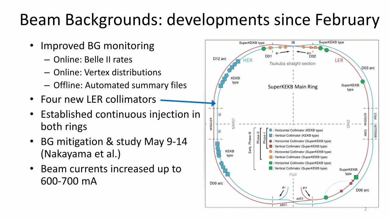
Beam Backgrounds: developments since February
• Improved BG monitoring– Online: Belle II rates
– Online: Vertex distributions
– Offline: Automated summary files
• Four new LER collimators
• Established continuous injection in both rings
• BG mitigation & study May 9-14 (Nakayama et al.)
• Beam currents increased up to 600-700 mA
2

Beam Background “big picture” (as of mid. June 2019)
• Machine parameters
– beta_y*=3mm, 1576bunch, 650+650mA, L~0.5*1034
• Our bottle-neck is CDC (and TOP)
– CDC HV trips with large BG (storage + injection)
– TOP PMT photocathode lifetime get shorter
• Dominant source: LER beam-gas BG
– Touschek BG is small enough, thanks to newly-installed horizontal collimators after phase2
• Keep good injection condition is very important
– To avoid CDC HV trip
– To avoid loss monitor aborts at collimators (and allow us to close the collimators even narrower)
Beam-gas
Touschek
LER single-beam study I=450mA, beta_y* = 3mm
Touschek scaling(beam size scan)
CD
C c
urr
ent
[uA
]
At the end of June, we moved to beta_y*=2mm optics. When L~1.2*1034 isachieved with 800mA, BG was three times too high to turn on Belle2. (Note that we didn’t have enough time for collimator optimization with 2mm optics)

New: Online Rate Monitoring (BCG)
• Total (storage + injection) bkg compared against 100% “alarm limits” • Clear how much headroom we have to raise beam currents• Detect when bkg conditions (e.g., injection backgrounds) deteriorate → take immediate action
• Most detectors: safety factors order 5-10. Exceeding 100% implies soft performance degradation, but not physical danger
• CDC and TOP <= 2, currently limiting beam currents• CDC: >100% can occur during injection spikes, causing HV trips,
significant downtime• TOP: >100% leads to unacceptable deterioration of PMT photocathode
and efficiency loss before 2020 (or 2021)
4
Limit is raised to 200uA
βy*=3mm, 1576 bunches, 600+600mA, L~0.5*1034
Schueler et al.
June 18, 2019, 500+500 mA
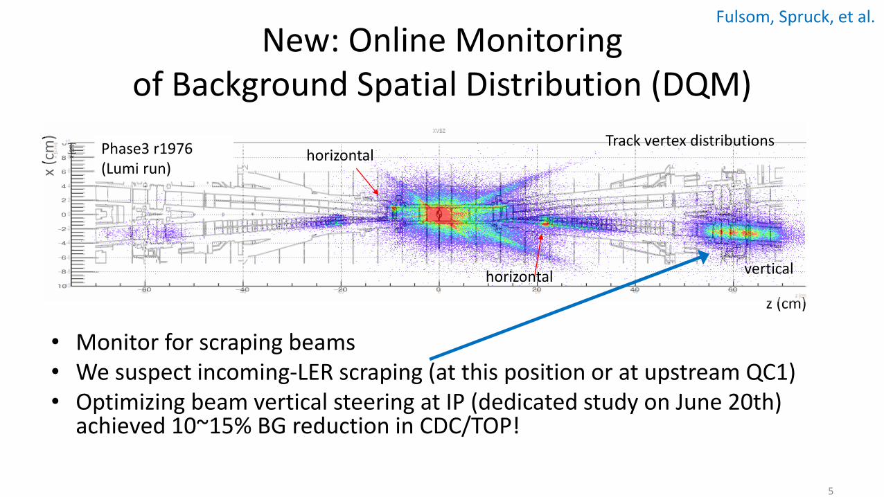
New: Online Monitoring of Background Spatial Distribution (DQM)
5
• Monitor for scraping beams• We suspect incoming-LER scraping (at this position or at upstream QC1)• Optimizing beam vertical steering at IP (dedicated study on June 20th)
achieved 10~15% BG reduction in CDC/TOP!
Fulsom, Spruck, et al.
z (cm)
x (c
m) Track vertex distributionsPhase3 r1976
(Lumi run)
verticalhorizontal
horizontal

Improved: fitting of single-beam storage backgrounds
• background studies performed May 11, 12, 14
• beam size scans and fill pattern scans now agree (LER), providing unambiguous estimate of background composition
• diamonds, PXD, SVD, TOP, analyzed in detail
• KLM, CDC groups have first results
• others detectors still forthcoming
Tanigawa
𝑅𝑎𝑡𝑒 = 𝑇 ×𝐼2
𝜎𝑦𝑛𝑏+ B × IP
Touschek Beam-gas
vary both 𝜎𝑦 and 𝑛𝑏 to change Touschek bkg normalization
Tou
sch
ek
Be
am-g
as
6

7
Tanigawa (SVD)
Diamonds, SVD, TOP well described by simple beam-gas + Touschek model PXD not yet fully understood, suspect due to Synchrotron Radiation
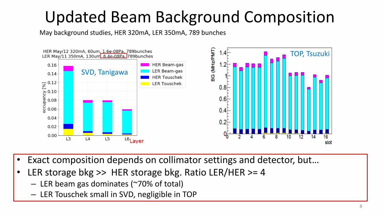
Updated Beam Background Composition
• Exact composition depends on collimator settings and detector, but…• LER storage bkg >> HER storage bkg. Ratio LER/HER >= 4
– LER beam gas dominates (~70% of total)– LER Touschek small in SVD, negligible in TOP
SVD, Tanigawa
TOP, Tsuzuki
May background studies, HER 320mA, LER 350mA, 789 bunches
8

Data vs. MC
• bkg simulation perfect data/mc = 1
• Typically, data/mc >1. We use data/mc as correction factor for simulation, for instance to estimate backgrounds at design luminosity
• Three groups have results– Diamonds: observe data/MC ~ 1
– SVD/TOP: shown to right
9
Tanigawa, Tsuzuki
From beam lifetime
• Total loss rate data/MC <=10. SAD simulation reasonably accurate.• LER Touschek: good.• HER Touschek: suspect simulation problem (Data rate is small. MC rate is toooo small). • Beam gas: data/mc high even for total loss rate. Note that dynamic pressure is already accounted for in these
ratios and does not include measured Zeff. Need to investigate beam-gas normalization. Gas injection study?
total loss SVD L3 (SVD L4-6) TOP
LER beam-gas 1.9-4.1 12-13 (5.4-6.9) 12
LER Touschek 1.3-1.8 1.0-1.1 (0.87-1.1) 0.16
HER beam-gas 10 16 (19-27) 7.7
HER Touschek 3 1600 (760-900) 510
Data/MC in SVD,TOP

Major issue: LER Dynamic Pressure
• Why is LER beam gas bkg so high?
• Because dynamic pressure is high in all of LER, especially in D02, where we installed collimators after Phase2
• We need to replace the collimator head of D02V1 damaged by June 9th
accident.
• Intensive vacuum scrubbing after the replacement is important!
10
𝑅𝑎𝑡𝑒 = 𝑇 ×𝐼2
𝜎𝑦𝑛𝑏+ B × IP
𝑅𝑎𝑡𝑒 = 𝑇 ×𝐼2
𝜎𝑦𝑛𝑏+ B’𝑍𝑒𝑓𝑓
2 × I(𝑃0+I dP/dI)
Vacuum scrubbing goal
Liptak
Touschek Beam-gas

11
L. Vitale
x40!
Can we minimize this delay?
Severe damage on inner detectors
Another major issue: Severe Background burstJune 9th
See Ikeda-san’s talk later
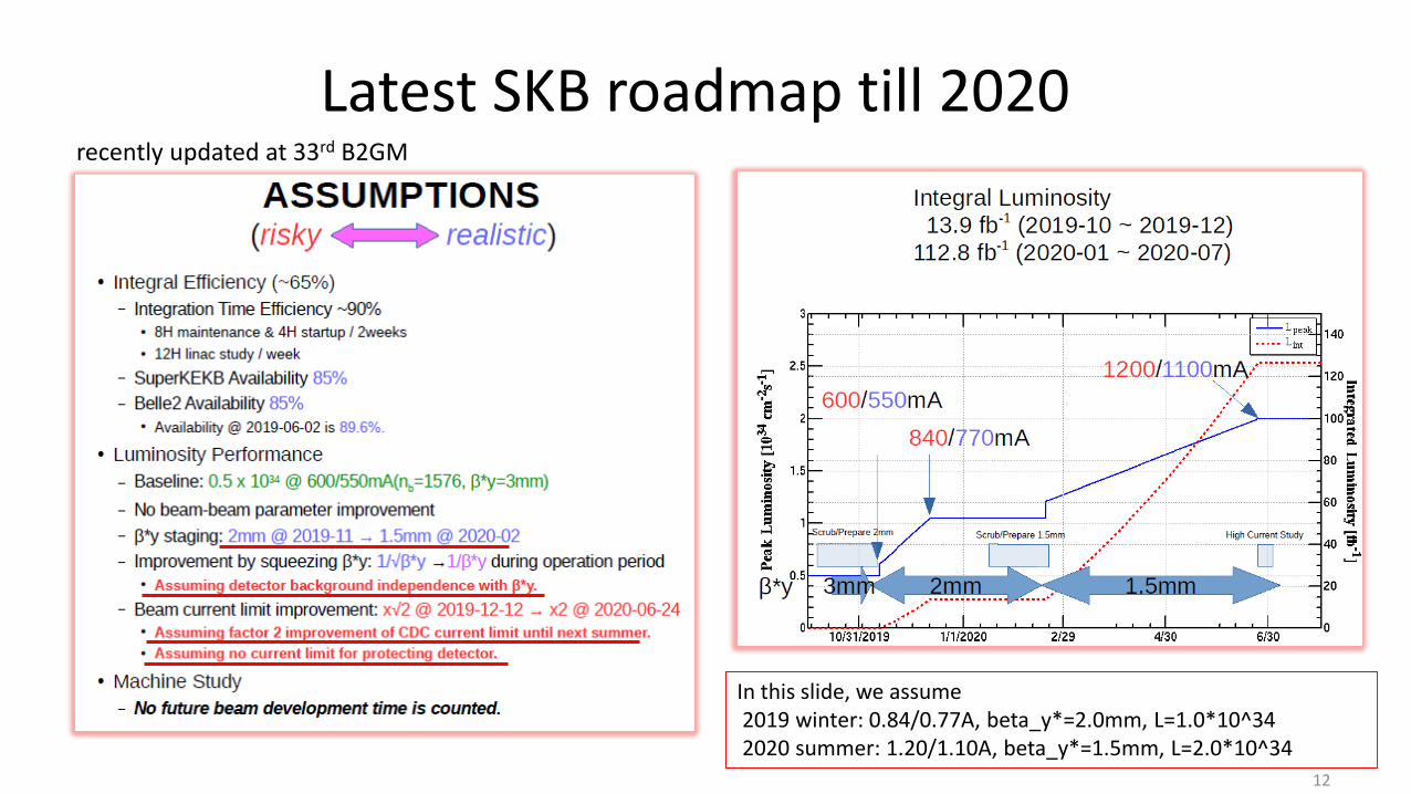
Latest SKB roadmap till 2020
12
In this slide, we assume2019 winter: 0.84/0.77A, beta_y*=2.0mm, L=1.0*10^342020 summer: 1.20/1.10A, beta_y*=1.5mm, L=2.0*10^34
recently updated at 33rd B2GM

BG extrapolation toward 2020 summer
LER Beam-gas 2019 winter 2020 summer
Beam current(I^2) x2(0.84A) x4(1.2A)
1/beta_y* x1.5 x2
Vacuum scrubbing (dP/dI) * x2/3 x1/2
Collimator reduction factor ** x1 x1
Total x2 x4
13
LER Touschek 2019 winter 2020 summer
Beam current (I^2) x2(0.84A) x4(1.2A)
Collimator reduction factor x1 x1
Total x2 x4
• HER Touschek, HER Beam-gas are assumed to be much smaller than LER also in 2020.
• Lumi-BG is not yet measured in Phase3. We expect x2(x4) lumi-BG in 2019(2020) than now, which we assume to be smaller than LER BG.
• Based on these assumptions, LER beam-gas will be still a dominant background source in 2020
In this slide, we assume2019 winter: 0.84/0.77A, beta_y*=2.0mm, L=1.0*10^342020 summer: 1.20/1.10A, beta_y*=1.5mm, L=2.0*10^34
Simply increasing beam currents will lead to intolerable BG, even with vacuum scrubbing
- New LER collimator(s)- Optics adjustments- Intensive vacuum scrubbing
* My personal guess** “x1” might be optimistic. Vertical collimation at squeezed optics will be more difficult
This extrapolation based on the scaling the latest BG measurement using machine parameters.Another approach is being prepared, to scale the BG simulation with future optics, using latest Data/MC ratio.

Possible Background Mitigation
• Possible options for reducing LER beam-gas – reduce dynamic pressure(dP/dI)
– adjust IP beam steering → it might also improve luminosity
– modify optics to match existing collimator phases better
– add LER vertical collimator(s) → Add D06V1 in 2019 winter shutdown. Add D03V1 next.
• Recommendation: pursue all four options
• Dynamic pressure reduction via– Intensive vacuum scrubbing period with detuned beams, Belle II off
– Beam pipe heating
– Additional / improved pumping (need beam pipe modification)
14
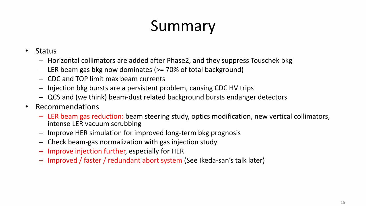
Summary
• Status– Horizontal collimators are added after Phase2, and they suppress Touschek bkg– LER beam gas bkg now dominates (>= 70% of total background)– CDC and TOP limit max beam currents– Injection bkg bursts are a persistent problem, causing CDC HV trips– QCS and (we think) beam-dust related background bursts endanger detectors
• Recommendations– LER beam gas reduction: beam steering study, optics modification, new vertical collimators,
intense LER vacuum scrubbing– Improve HER simulation for improved long-term bkg prognosis– Check beam-gas normalization with gas injection study – Improve injection further, especially for HER– Improved / faster / redundant abort system (See Ikeda-san’s talk later)
15

backup
16

High Level StatusGenerally speaking, we want to measure, fully understand, and mitigate the following beam background components to safe levels
17
Background Component Simulation Method
Touschek SAD (accelerator tracking code) generates and tracks scattered particles. If lost near IP: passed to GEANT4.
Beam-gas Coulomb
Beam-gas Bremsstrahlung
Radiative Bhabha BBBrem/BHWide→ GEANT4
QED 2-photon Aafh→ GEANT4
Synchrotron Radiation SR generation in GEANT4
Injection BG Injection particles provided by accelerator group→ SAD →GEANT4
Beam dust -
Neutrons All of above
Measured in early phase3. Too high for going higher currents.Large data/mc discrepancy
Expected to dominate at higher LuminosityMarginal observation in early phase3Lowest simulation uncertainty.
measured in early phase3LER injection BG is very cleanmitigation is purely experimental(injection tuning is not simulation based)
measured in early phase3. ~OK
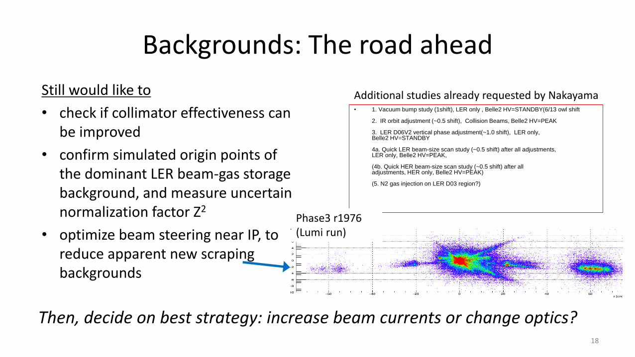
Backgrounds: The road ahead
Still would like to
• check if collimator effectiveness can be improved
• confirm simulated origin points of the dominant LER beam-gas storage background, and measure uncertain normalization factor Z2
• optimize beam steering near IP, to reduce apparent new scraping backgrounds
• 1. Vacuum bump study (1shift), LER only , Belle2 HV=STANDBY(6/13 owl shift
2. IR orbit adjustment (~0.5 shift), Collision Beams, Belle2 HV=PEAK
3. LER D06V2 vertical phase adjustment(~1.0 shift), LER only,Belle2 HV=STANDBY
4a. Quick LER beam-size scan study (~0.5 shift) after all adjustments,LER only, Belle2 HV=PEAK,
(4b. Quick HER beam-size scan study (~0.5 shift) after alladjustments, HER only, Belle2 HV=PEAK)
(5. N2 gas injection on LER D03 region?)
Then, decide on best strategy: increase beam currents or change optics?
Additional studies already requested by Nakayama
Phase3 r1976 (Lumi run)
18

My *PERSONAL* understandings/guess on the current BG situation
19
• LER beam-gas scattered particles are lost vertically inside QC1RP, at z=+1.1m. Simulation can reliably predict it.• Showers generated at z+1m develops toward –z direction and reaches to QCS bellows at z=0.6m. If the showers are still localized in +y or –y direction at
z=0.6m (should be confirmed by Geant4 simulation), it can explain observed V0 vertex distribution • There are no shielding around z=0.6m, so the secondary particles generated at the material in that region (bellows flanges etc.) can be directly seen by
outer detectors (CDC,TOP,…) and therefore becomes dominant BG source
• We observe D02V1BTM is more effective to suppress BG rates than D02V1TOP. Since LER D02V1 and QC1RP have opposite nu_y, D02V1BTM can suppress +y loss at QC1RP. This supports the hypothesis the hot spots on bellows are originated from loss in QC1RP.
• Data/MC ratio should be revisited after using section-by-section pressure values in MC. Z_eff difference should also be taken into account
QCS FW bellows
QC1RP
e+ loss
QC1RP
y[cm
]
y[cm]
Shower escapesfrom QCS
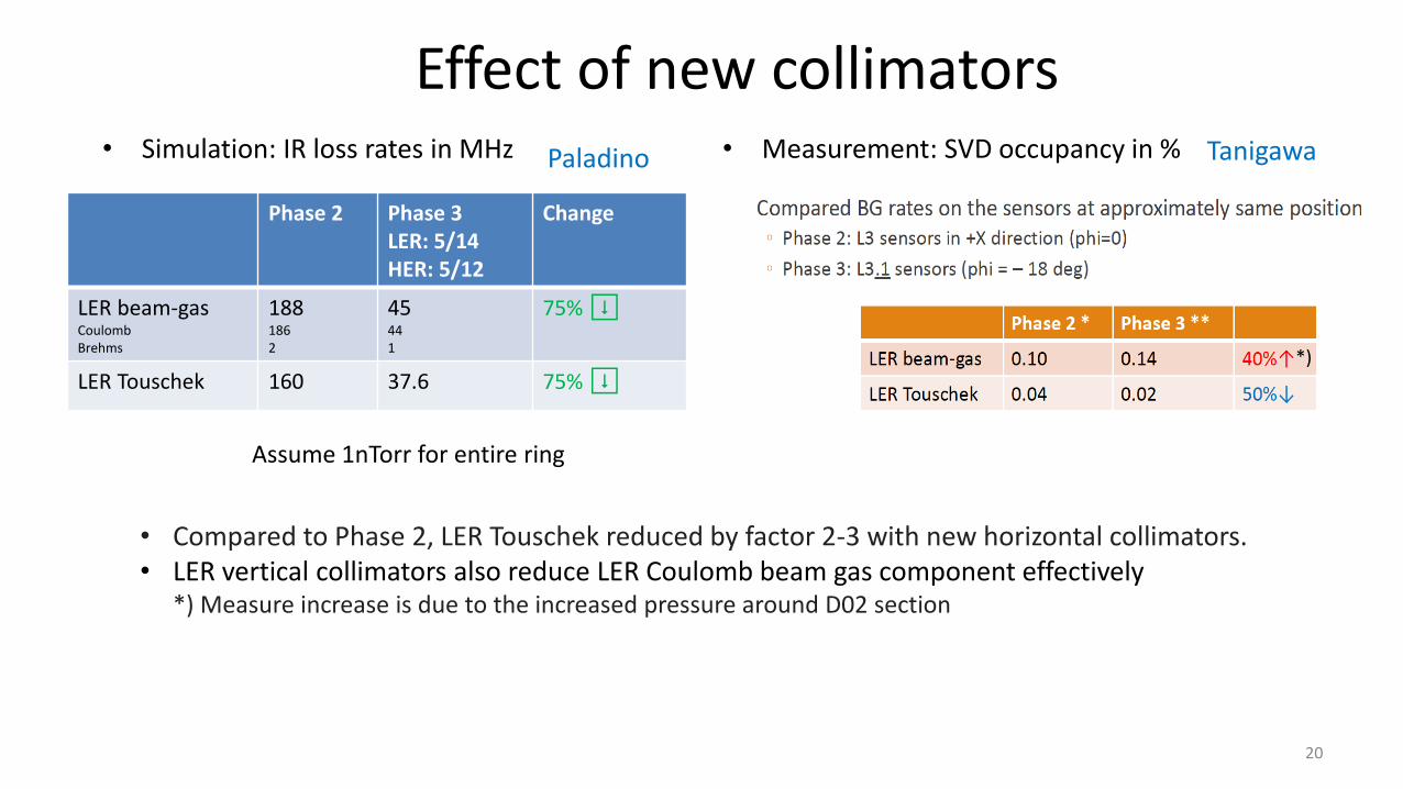
Effect of new collimators• Simulation: IR loss rates in MHz • Measurement: SVD occupancy in %
• Compared to Phase 2, LER Touschek reduced by factor 2-3 with new horizontal collimators.• LER vertical collimators also reduce LER Coulomb beam gas component effectively
*) Measure increase is due to the increased pressure around D02 section
Phase 2 Phase 3LER: 5/14HER: 5/12
Change
LER beam-gasCoulombBrehms
1881862
45441
75% ⬇
LER Touschek 160 37.6 75% ⬇
TanigawaPaladino
20
Assume 1nTorr for entire ring
*)
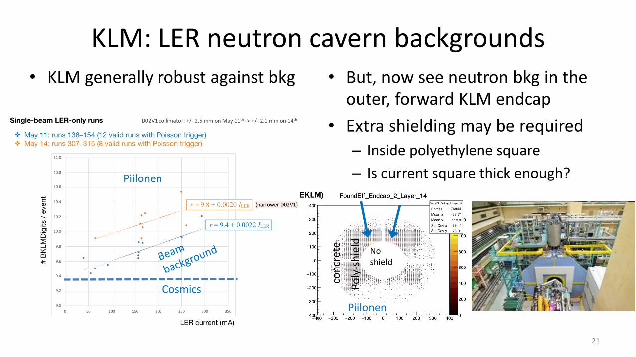
KLM: LER neutron cavern backgrounds• KLM generally robust against bkg • But, now see neutron bkg in the
outer, forward KLM endcap
• Extra shielding may be required
– Inside polyethylene square
– Is current square thick enough?
21
Piilonen
Cosmics
Piilonen
con
cret
e
Poly
-sh
ield
Noshield

Neutron source? Touschek!?• TPC fast neutron detectors
now mounted in accelerator tunnel
• Suggest KLM endcap neutrons originate from Touschek background (surprise!)
• Generated at upstream collimators? More work needed to investigate.
22
Schueler
𝐼
𝑃𝜎𝑦𝑁𝑏𝑍𝑒2
mA
Pa⋅𝜇m⋅e2
RecoilRate
𝐼𝑃𝑍𝑒2
Hz
mA⋅Pa⋅e2
Data points are averaged over 300s
𝑁𝑏 = 1576
𝑁𝑏 = 789𝑁𝑏 = 395
Knob 0 Tou
sch
ek
Beam-gas

Beam BG extrapolationtoward 2020 summer
H. Nakayama (KEK)
2019 June BPAC
23

Latest roadmap toward 2020
24
In this slide, we assume2019 winter: 0.84/0.77A, beta_y*=2.0mm, L=1.0*10^342020 summer: 1.20/1.10A, beta_y*=1.5mm, L=2.0*10^34
Updated by SKB group at the 33rd B2GM last week.
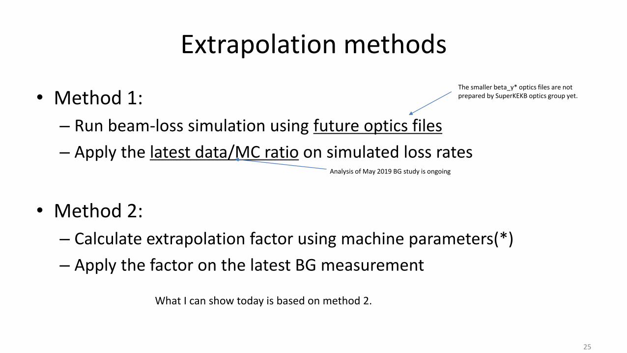
Extrapolation methods
• Method 1:
– Run beam-loss simulation using future optics files
– Apply the latest data/MC ratio on simulated loss rates
• Method 2:
– Calculate extrapolation factor using machine parameters(*)
– Apply the factor on the latest BG measurement
25
The smaller beta_y* optics files are not prepared by SuperKEKB optics group yet.
Analysis of May 2019 BG study is ongoing
What I can show today is based on method 2.

Extrapolation based on machine parameters
• Touschek BG:– Proportional to I^2– Assume the same collimator reduction factor
• LER horizontal collimators should be narrowed (bx*: 200mm to 100mm)• Re-optimization seems possible
• Beam-gas Coulomb BG:– Proportional to P * I * / by*. (Note that P=P0+dP/dI *I, almost proportional to I)
• Vacuum scrubbing can reduce IR loss • Assume factor 2/3 for 2019 winter and factor 1/2 for 2020 summer (my personal guess!)• Installing a new collimator makes the vacuum worse
– Assume the same collimator reduction factor(*)• We need to further close LER vertical collimators as by* goes 3.0→2.0→1.5mm• LER vertical collimators are already very tight. Can we really close them further without beam instability or injection
loss monitor abort?? This assumption might be optimistic.
26

BG extrapolation toward 2020 summer
LER Beam-gas 2019 winter 2020 summer
Beam current(I^2) x2(0.84A) x4(1.2A)
1/beta_y* x1.5 x2
Vacuum scrubbing (dP/dI) x2/3 x1/2
Collimator reduction factor x1* x1*
Total x2 x427
LER Touschek 2019 winter 2020 summer
Beam current (I^2) x2(0.84A) x4(1.2A)
Collimator reduction factor x1 x1
Total x2 x4
• HER Touschek, HER Beam-gas are assumed to be much smaller than LER also in 2020.
• Lumi-BG is not yet measured in Phase3. We expect x2(x4) lumi-BG in 2019(2020) than now, which we assume to be smaller than LER BG.
• Based on these assumptions, LER beam-gas will be still a dominant background source in 2020
In this slide, we assume2019 winter: 0.84/0.77A, beta_y*=2.0mm, L=1.0*10^342020 summer: 1.20/1.10A, beta_y*=1.5mm, L=2.0*10^34
Simply increasing beam currents will lead to intolerable BG, even with vacuum scrubbing
- New LER collimator(s)- Optics adjustments

Mitigation ideas?
• IR orbit adjustment– 10~15% reduction seen during vertical orbit scan (June 20th)
• Add more LER vertical collimator(s)– It could reduce LER beam-gas BG.– The location of the new collimator is being discussed (D06V1/D03V1/D03V2)
• Intensive vacuum scrubbing at LER D02 section– Still worse vacuum (breached by collimator work before 2019 spring run)– Reinforcement on pumping? (need beam pipe remodeling work)
• LER D06V2 vertical phase adjustment– Change wiggler section phase advance to adjust D06V2 phase– A big work, study is postponed to winter run or later
• LER D02V1 vertical phase improves as beta_y* squeezed– Not a big effect at beta_y* = 2mm or 1.5mm
IR orbit adjustment
29
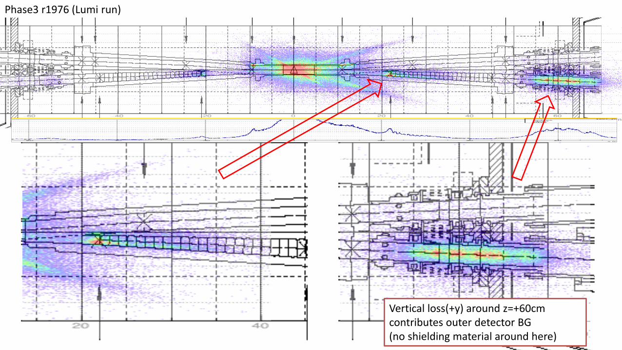
Phase3 r1976 (Lumi run)
Vertical loss(+y) around z=+60cm contributes outer detector BG(no shielding material around here)

BG reduction by IR orbit vertical scan
2019/7/5 33rd B2GM 31
LER upstream orbit is moved downward by 0.4~0.5mm around QC1
Vertical orbit angle shiftJune 20th (TODAY)
TOP/CDC/ECL rates decreased by 10~15%
QCS_FWD diamonds rate decreased by 40%
PXD/SVD occupancies did not change significantly

Vo vertex x-y view at z=+60cmbefore/after vertical IR orbit scan
Dy=-0.4mmDy=0
1hour 0.5hour
Run 2747 Run 2750
10~15% BG reduction in TOP/CDC!!
NEW LER collimators
33

Add LER V collimator for 2020
• D06V1– Pro: Good phase, can effectively reduce IR loss and reduce burden on D02V1
– Pro: Large beta_y (easier handling)
– Con: far from IP (no impact on particles scattered in D06-D03)
• D03V1– Pro: near from IP
– Con: unmatched phase, but might have some impact on particles scattered in D06-D03
• D03V2– Pro: completely unmatched phase, might be effective to protect IR from crazy beam
– Pro?: near from IP, but it does not help because of ↓
– Con: completely unmatched phase, expect no impact on particles scattered in D06-D03
D6V1
D6V2
D2V1
D3V1
D3V2
I propose to install D06V1 in 2019 winter shutdown. For the next opportunity, I propose to install D03V1.
(2.0/1.5mm optics)
Vacuum bump study on June 13th suggests beam-gas scattering at D01/D12-D07 can contribute to IR lossCon: impedance budget issue at design optics and full current
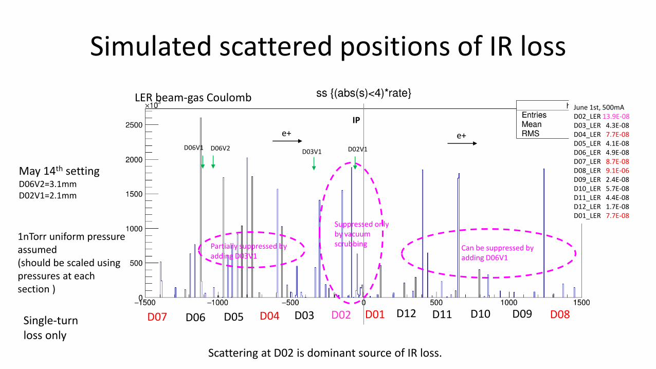
Simulated scattered positions of IR loss
May 14th settingD06V2=3.1mmD02V1=2.1mm
1nTorr uniform pressure assumed(should be scaled using pressures at each section )
e+
D02D03D04D05D06D07 D01 D12 D11 D10 D09 D08
D06V2 D02V1
June 1st, 500mAD02_LER 13.9E-08D03_LER 4.3E-08D04_LER 7.7E-08D05_LER 4.1E-08D06_LER 4.9E-08D07_LER 8.7E-08D08_LER 9.1E-06D09_LER 2.4E-08D10_LER 5.7E-08D11_LER 4.4E-08D12_LER 1.7E-08D01_LER 7.7E-08
LER beam-gas Coulomb
e+D06V1
D03V1
Can be suppressed by adding D06V1
Partially suppressed by adding D03V1
Suppressed only by vacuum scrubbing
Scattering at D02 is dominant source of IR loss.
IP
Single-turn loss only

Summary
• Simple extrapolation using machine parameters shows:– x2 BG rates at 0.84/0.77A, beta_y*=2mm (2019 winter)
– x4 BG rates in 1.20/1.10A, beta_y*=1.5mm (2020 summer)
– Preparing detailed extrapolation using latest data/MC ratio
• Further BG reduction is necessary to achieve higher currents planned for 2020.
• New LER V collimator(s), intensive LER vacuum scrubbing, and optics adjustments are important.
36

Additional LER V collimator for 2020
Candidate location: D06V1, D03V1, D03V2
Vertical betatron phaseat beta_y*=2mm (0.27mm)
beta_y Distance from IP
D06V1 +0.04 (+0.10) 61m Far(-1146m)
D03V1 +0.12 (+0.17) 17m Near(-301m)
D03V2 +0.28 (+0.34) 17m Near(-225m)
Comment
Closer phase with QC1R? →D06V1 preferred.Diversity in phase to stop crazy beam? → D03V1/V2
D06V1 can be used with wider width, but we face impedance budget issue with large beta_y at full current.
Beam-gas scattering at near section can only be stopped by near collimators (single-turn loss).
D06V2: +0.18 (+0.24)D02V1: +0.06 (+0.01)
D06V2: 19mD02V1: 20m (110m)
Possibility to move D06V2 to other place?
Phase adjustment for D06 collimators is really possible?
D06V2: -1026mD02V1: -82mD6V1
D6V2
D2V1
D3V1
D3V2
beta_y*=2mm
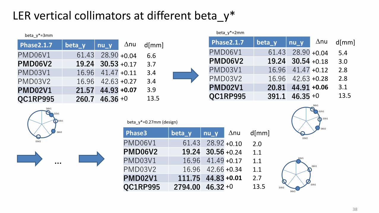
38
Phase2.1.7 beta_y nu_y
PMD06V1 61.43 28.90PMD06V2 19.24 30.53PMD03V1 16.96 41.47PMD03V2 16.96 42.63PMD02V1 21.57 44.93QC1RP995 260.7 46.36
Phase3 beta_y nu_y
PMD06V1 61.43 28.92PMD06V2 19.24 30.56PMD03V1 16.96 41.49PMD03V2 16.96 42.66PMD02V1 111.75 44.83QC1RP995 2794.00 46.32
+0.04+0.17+0.11+0.27+0.07+0
+0.10+0.24+0.17+0.34+0.01+0
6.63.73.43.43.913.5
2.01.11.11.12.713.5
d[mm]Dnu
Dnu d[mm]
beta_y*=3mm
beta_y*=0.27mm (design)
Phase2.1.7 beta_y nu_y
PMD06V1 61.43 28.90PMD06V2 19.24 30.54PMD03V1 16.96 41.47PMD03V2 16.96 42.63PMD02V1 20.81 44.91QC1RP995 391.1 46.35
+0.04+0.18+0.12+0.28+0.06+0
5.43.02.82.83.113.5
d[mm]Dnu
beta_y*=2mm
LER vertical collimators at different beta_y*
…
D6V1
D6V2
D2V1
D3V1
D3V2
D6V1
D6V2
D2V1
D3V1
D3V2
D6V1
D3V2
D2V1
D3V1
D6V2

Beam abort
39
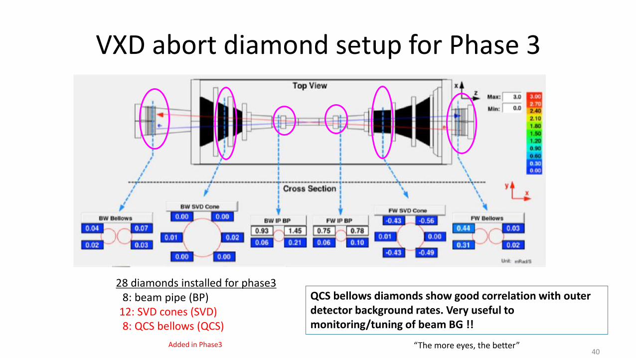
VXD abort diamond setup for Phase 3
40
28 diamonds installed for phase38: beam pipe (BP)
12: SVD cones (SVD)8: QCS bellows (QCS)
QCS bellows diamonds show good correlation with outer detector background rates. Very useful to monitoring/tuning of beam BG !!
“The more eyes, the better”Added in Phase3

VXD abort diamonds~lessons from recent QCS quench accidents~
• Two severe QCS quenches in Phase 3– QCS quench on May 28th: caused by QCS power supply failure
– QCS quench on June 9th : probably caused by “beam-dust” event
– Serious damage on Belle2 sensors and collimator head
• Protection by VXD diamond– At May 28th event, diamonds were saturated and didn’t issue the beam abort.
• accelerator loss monitors issued the abort earlier than diamonds
– Diamond gain/threshold were adjusted on June 6th
– At June 9th event, diamonds issued the beam abort !• earliest abort among all abort sensors in the ring
• however.. (see next page)
41
A tiny dust in the beam pipe vacuum falls onto the beam and get trapped

42
L. Vitale
x40!
Can we minimize this delay?
Severe damage on inner detectors
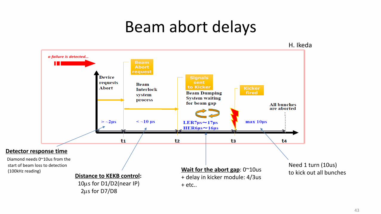
Beam abort delays
43
H. Ikeda
Distance to KEKB control: 10ms for D1/D2(near IP)
2ms for D7/D8
Wait for the abort gap: 0~10us+ delay in kicker module: 4/3us+ etc..
Need 1 turn (10us) to kick out all bunches
Detector response timeDiamond needs 0~10us from the
start of beam loss to detection(100kHz reading)

Ideas for minimizing the abort delay
Shorter detector response time– Lower threshold on loss monitor PINs (need to veto injection spikes)
– Faster VXD diamond sampling rate (for example, 200kHz sampling) → 0~5us faster
Shorter distance to KEKB control– Beam loss detection by a monitor near KEKB control, not IP → 0~8us faster
Shorter waiting time for abort gap– Increase abort gap from 1 to 2 → 0~5us faster (~1year to update the system)
44
All possibilities are under active discussion in MDI group
SKB sideBelle2 side

Recent BG studies
45

LER single-beam study on June 9th, 2019
H. Nakayama(KEK)
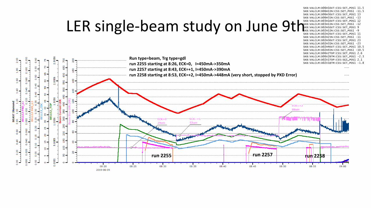
LER single-beam study on June 9th
run 2255 run 2257 run 2258
Run type=beam, Trg type=gdlrun 2255 starting at 8:26, ECK=0, I=450mA->350mArun 2257 starting at 8:43, ECK=+1, I=450mA->390mArun 2258 starting at 8:53, ECK=+2, I=450mA->448mA (very short, stopped by PXD Error)
SKB:VALCLM:D06H1OUT:CSS:SET_POS1 11.5SKB:VALCLM:D06H1IN:CSS:SET_POS1 -11.5SKB:VALCLM:D06H3OUT:CSS:SET_POS1 13SKB:VALCLM:D06H3IN:CSS:SET_POS1 -13SKB:VALCLM:D03H1OUT:CSS:SET_POS1 12SKB:VALCLM:D03H1IN:CSS:SET_POS1 -12SKB:VALCLM:D02H1OUT:CSS:SET_POS1 9SKB:VALCLM:D02H1IN:CSS:SET_POS1 -9SKB:VALCLM:D02H2OUT:CSS:SET_POS1 11SKB:VALCLM:D02H2IN:CSS:SET_POS1 -11SKB:VALCLM:D02H3OUT:CSS:SET_POS1 23SKB:VALCLM:D02H3IN:CSS:SET_POS1 -23SKB:VALCLM:D02H4OUT:CSS:SET_POS1 10.5SKB:VALCLM:D02H4IN:CSS:SET_POS1 -10.5SKB:VALCLM:D06V2TOP:CSS:SET_POS1 2.6SKB:VALCLM:D06V2BTM:CSS:SET_POS1 -2.3SKB:VALCLM:D02V1TOP:CSS:SET_POS1 2.1SKB:VALCLM:D02V1BTM:CSS:SET_POS1 -1.8

Belle2 rates vs. beam size
At 450mA and 100um(nominal beam size during collision), LER Touschek is <10% in outer detectors and QCS_FW diamonds, ~17% in PXD and BP diamonds
LER single-beam study on June 9th, I=450mA

LER Vacuum bump studyon June 13th
Hiro Nakayama (KEK)

- NEG heating at all (tried) sections had impact on diamond rates as predicted by simulation→ installing D06V1 (far from IP) can still suppress loss from D07-D12, D01
- D02, D06, D11 seems more sensitive than other sections- Diamonds on beam pipe, QCS_FW bellows, QCS_BW bellows showed proportional increase in most cases,
but the response was different for D02 bump (near IP). - Beam pipe diamonds directly sees interaction with beam and gas in IP beam-pipe?
LER Vacuum bump study on June 13th Pressures are shown in log scale!!

Simulated scattered positions of IR loss
May 14th settingD06V2=3.1mmD02V1=2.1mm
1nTorr uniform pressure assumed(should be scaled using pressures at each section )
e+
D02D03D04D05D06D07 D01 D12 D11 D10 D09 D08
D06V2 D02V1
June 1st, 500mAD02_LER 13.9E-08D03_LER 4.3E-08D04_LER 7.7E-08D05_LER 4.1E-08D06_LER 4.9E-08D07_LER 8.7E-08D08_LER 9.1E-06D09_LER 2.4E-08D10_LER 5.7E-08D11_LER 4.4E-08D12_LER 1.7E-08D01_LER 7.7E-08
LER beam-gas Coulomb
e+D06V1
D03V1
Can be suppressed by adding D06V1
Partially suppressed by adding D03V1
Suppressed only by vacuum scrubbing
Scattering at D02 is dominant source of IR loss.
IP
Single-turn loss only
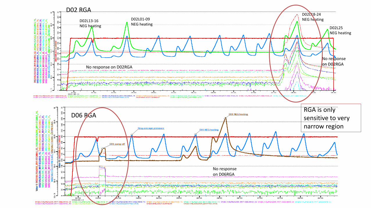
D02 RGA
D06 RGA
D02L18-24NEG heating
RGA is only sensitive to very narrow region
D02L25NEG heating
D02L01-09NEG heating
D02L13-16NEG heating
No response on D02RGA
No response on D02RGA
No response on D06RGA

LER orbit scan studyon June 20th, 2019
Hiro Nakayama (KEK)

LER orbit scan study on June 20th
Vertical orbit position
Horizontal orbit position
dy=-0.4mm@QC1
dx=+0.3mm@QC1
dpy=-1.0mrad (move LER upstream orbit vertically downward)--> Diamond(QCS_FW) decreased by 30%, CDC/TOP decreased by ~15%, SVDL3/PXDL1 didn't change.--> Luminosity becomes better (HER size smaller)--> V0 hotspot at z=60cm moved from +Y to -Y.
dpx=-0.3mrad (move LER upstream/downstream orbit closer to Belle2 solenoid axis)--> no significant change in Belle2/diamond rates, V0 hot spot, luminosity.
Run 2747Run 2750 Run 2755
Lumi
Dia(BP)Dia(FW)TOPCDCSVDPXD
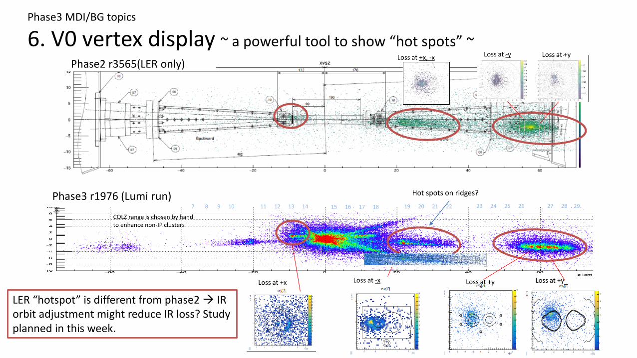
Phase2 r3565(LER only)Phase2 r3565(LER only)
Phase3 r1976 (Lumi run)
COLZ range is chosen by hand to enhance non-IP clusters
19 20 21 22 23 24 25 26 27 28 2911 12 13 147 8 9 10
Loss at +x Loss at -x Loss at +y
Loss at -y Loss at +y
15 16 17 18
Loss at +x, -x
Phase3 MDI/BG topics
6. V0 vertex display ~ a powerful tool to show “hot spots” ~
LER “hotspot” is different from phase2 → IR orbit adjustment might reduce IR loss? Study planned in this week.
Loss at +y
Hot spots on ridges?

Phase3 r1976 (Lumi run)

x-y view at z=+60cmbefore/after vertical IR orbit scan
Dy=-0.4mmDy=0
1hour 0.5hour
Run 2747 Run 2750

Phase3 Beast detectors
58

BEAST Detectors in Phase 3• Most of “BEAST” retired
• A few dedicated BG detectors remain• Diamonds
• CLAWS++ on QCS
• PINs on QCS
• He-3 in tunnel
• TPCs in tunnel
• BEAST online DAQ for BG monitoring via EPICS will keep running
59
• We will display rates + rate limits of all Belle II and BEAST detectors in SuperKEKB control room (see BCG meeting talk by Jeff Schueler)
• BCG Shifters will monitor BEAST, call experts if there is trouble
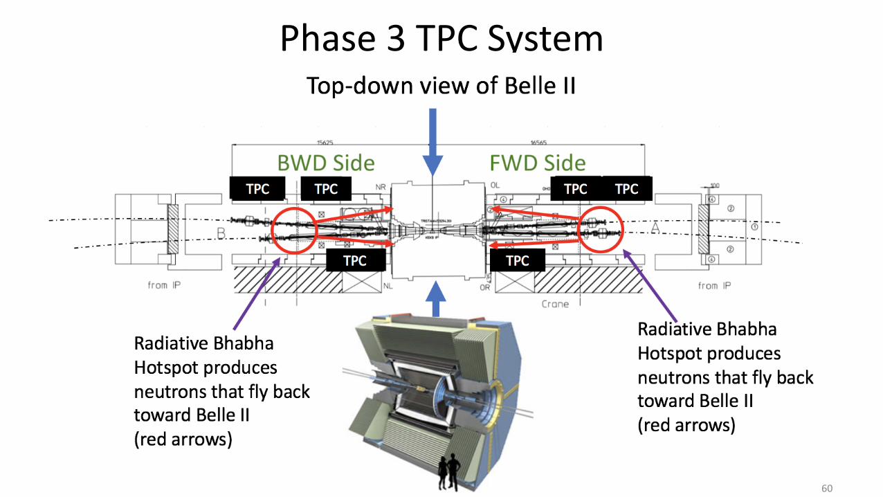
Phase 3 TPC System
60
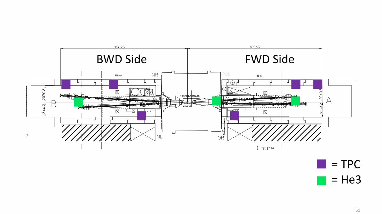
FWD SideBWD Side
= TPC= He3
61