bearing capacity of concrete hinges subjected to eccentric
TRANSCRIPT

Acta Mech 229, 849–866 (2018)https://doi.org/10.1007/s00707-017-2004-3
ORIGINAL PAPER
Johannes Kalliauer · Thomas Schlappal · Markus Vill ·Herbert Mang · Bernhard Pichler
Bearing capacity of concrete hinges subjected to eccentriccompression: multiscale structural analysis of experimentsThis paper is dedicated to the memory of Franz Ziegler
Received: 24 March 2017 / Revised: 11 June 2017 / Published online: 17 January 2018© The Author(s) 2018. This article is an open access publication
Abstract Existing design guidelines for concrete hinges are focusing on serviceability limit states. Lack ofknowledge about ultimate limit states was the motivation for this work. Experimental data are taken from atesting series on reinforced concrete hinges subjected to eccentric compression up to their bearing capacity.These tests are simulated using the finite element (FE) softwareAtena science and amaterialmodel for concreteimplemented therein. The first simulation is based on default input derived from measured values of Young’smodulus and of the cube compressive strength of the concrete. The numerical results overestimate the initialstiffness and the bearing capacity of the tested concrete hinges. Therefore, it is concluded that concrete wasdamaged already before the tests. A multiscale model for tensile failure of concrete is used to correlate thepreexisting damage to corresponding values of Young’s modulus, the tensile strength, and the fracture energyof concrete. This allows for identifying the preexisting damage in the context of correlated structural sensitivityanalyses, such that the simulated initial stiffness agrees well with experimental data. In order to simulate thebearing capacity adequately, the triaxial compressive strength of concrete is reduced to a level that is consistentwith regulations according to Eurocode 2. Corresponding FE simulations suggest that the ductile structuralfailure of concrete hinges results from the ductile material failure of concrete at the surface of the compressedlateral notch. Finally, Eurocode-inspired interaction envelopes for concrete hinges subjected to compressionand bending are derived. They agree well with the experimental data.
List of symbols
a Neck widthag Maximum aggregate sizeb1 Width of the partially loaded area Ac0b2 Width of the partially loaded area Ac1c Softening parameterc1, c2 Coefficients appearing in the crack opening law
J. Kalliauer · T. Schlappal · H. Mang · B. Pichler (B)Institute for Mechanics of Materials and Structures, TU Wien – Vienna University of Technology,Karlsplatz 13/202, 1040 Vienna, AustriaE-mail: [email protected].: +43-58801-20224Fax: +43-588019-20224
M. VillVill Ziviltechniker GmbH, Hermanngasse 18, 1070 Vienna, Austria
H. MangCollege of Civil Engineering, Tongji University, Siping Road 1239, Shanghai 200092, China
850 J. Kalliauer et al.
cini Initial value of cd1 Depth of the partially loaded area Ac0d2 Depth of the partially loaded area Ac1e Eccentricity of the normal forceeσ Parameter influencing the Menétrey–Willam failure surface in the deviatoric planeex , ey, ez base vectors in x , y, and z-directionfc Uniaxial compressive strengthfc0 Initial elastic limit under uniaxial compressionf ′c Evolving elastic limit under uniaxial compressionfcd Design value of the uniaxial compressive strengthfck Characteristic value of the uniaxial compressive strengthfc,cube Mean value of the cube compressive strengthfck,cube Characteristic value of the cube compressive strengthft Uniaxial tensile strength of the Rankine failure surfacef ′t Uniaxial tensile strength of the Menétrey–Willam failure surfaceft,dam Uniaxial tensile strength of damaged concretem Parameter influencing the shape of the Menétrey–Willam failure surfacerc Reduction of uniaxial compressive strength, due to crackswith crack-plane normal vectors
orthogonal to the loading directionw Crack opening displacementwc Value of w corresponding to the vanishing cohesive stresswd Critical compression displacementwdam Value of w due to preexisting damagex, y, z Cartesian coordinatesAc0 Partially loaded areaAc1 Distribution area with a similar shape to Ac0E Young’s modulusEc Young’s modulus of uncracked concreteEc,dam Young’s modulus of damaged concreteF p3P Failure function of the Menétrey and Willam criterion
FRdu Maximum design compressive forceFixed Flag for modeling of crack rotation: Fixed = 1 … no crack rotationG f Fracture energyG f,dam Fracture energy of damaged concreteKIc Fracture toughnessM Bending momentN Normal forceβ Flag for modeling the direction of the plastic flow: β = 0 . . . purely deviatoric plastic
flowΔG f Reduction of fracture energy due to preexisting damageΔϕ Rotation angleεpc Plastic strain at uniaxial compressive strength
ϑ Lode angleλt Auxiliary-to-actual uniaxial tensile strength ratioν Poisson’s ratioνc Poisson’s ratio of uncracked concreteξ Hydrostatic stress invariantρ Deviatoric stress invariantσ Softening tensile strength of smeared crack modelσ Cauchy stress tensorσ1, σ2, σ3 Principal stressesσ� Principal normal stress in the loading directionσ�u Maximum normal stress in the loading directionσy von Mises yield stress of steelω Crack density parameter
Bearing capacity of concrete hinges 851
1 Introduction
Concrete hinges were invented by Freyssinet [13,14]. They are unreinforced or marginally reinforced necksin reinforced concrete structures [30,37]. In practical engineering, they are used as supports in bridge con-struction [30,34,36–38] and as segment-to-segment interfaces of segmented linings used in mechanized tun-neling [3,11,21,22,28]. In the latter context, concrete hinges are one of the main challenges for finite element(FE) simulations of segmented tunnels [10,18,24,29,40,42]. Eventually, a few pairs of crossed steel rebars(or bolts) run across a concrete hinge. Their crossover point is typically at the center of the neck. Therefore,the bending stiffness of the neck is significantly smaller than that of the two connected reinforced concreteparts. The corresponding concentration of bending deformations at the concrete hinge results—already underregular service loads—in tension-induced cracking of initially monolithic necks [26,27,30–32], or in partialseparation of segment-to-segment interfaces [16,21]. Both effects reduce the bending stiffness of the neck.This increases the rotational compliance of concrete hinges, characterized by large, concentrated rotations ofcross sections.
Pioneering design guidelines for concrete hinges were developed by Leonhardt and Reimann [27]. Theyrefer to the deterministic safety concept used in the 1960s. Given that nowadays a semi-probabilistic safetyconcept is used, Marx [30] translated the guidelines by Leonhardt and Reimann into the nomenclature ofmodern European design standards. The latter require consideration of both serviceability limit states (SLS)and ultimate limit states (ULS). Notably, the guidelines by Leonhardt and Reimann focus rather on the SLS.This has provided the motivation for the present contribution. It is devoted to the structural re-analysis of atest series regarding the bearing capacity of concrete hinges, subjected to eccentric compression [39].
The aims of the present contribution are (1) to identify the mechanisms which render failure of concretehinges in a very ductile fashion possible, and (2) to check whether or not a Eurocode-inspired failure envelopecan provide reasonable estimates of the bearing capacity of concrete hinges subjected to compression andbending. As for the first aim, nonlinear FE simulations are carried out with the software Atena science anda material model for concrete implemented therein [8]. Two-dimensional plane strain simulations and three-dimensional simulations are carried out in order to gain insight into (1) the triaxiality of compressive stressstates in the neck region, and (2) the structural behavior of concrete hinges under eccentric compression rightup to the their bearing capacity. As for the second aim, Eurocode regulations for partially loaded areas [4]are the starting point for the derivation of failure envelopes for concrete hinges subjected to compression andbending.
In the context of reproducing experimental measurements by means of three-dimensional FE analyses, thenumber of fitting parameters required is kept as small as possible. This is accomplished by combining thestructural FE model with a recently developed multiscale material model for tensile failure of concrete [19].The micromechanics-based model considers interacting cracks as microstructural entities of concrete. As thedamage variable, the Budiansky andO’Connell crack density parameter is used [5]. The described combinationof models allows for correlated structural sensitivity analyses. Input values of Young’s modulus, the tensilestrength, and the fracture energy of concrete are prescribed such that they refer to one and only one value ofthe crack density. This reduces the number of fitting parameters from three to one and results in a multiscalestructural analysis of concrete hinges.
The manuscript is structured as follows. In Sect. 2 experimental data on concrete hinges subjected toeccentric compression are summarized. Section 3 is devoted to nonlinear FE simulations of concrete hinges,carried out in the framework of multiscale structural analysis. Section 4 deals with the derivation of failureenvelopes for concrete hinges subjected to compression and bending. Section 5 contains discussions of theobtained results. Conclusions of the present study are presented in Sect. 6.
2 Experimental data from testing of concrete hinges, taken from [39]
The tested reinforced concrete hinges consisted of concrete that was produced with a commercial CEMII/A-L42.5N cement, Viennese tab water, and calcite aggregates exhibiting a maximum size of 16mm. The initialwater-to-cement and aggregate-to-cement mass ratios amounted to 0.48 and 3.97, respectively. The cubecompressive strength, fc,cube, and Young’s modulus, E , were determined 28 days after production, followingthe Austrian standards for testing of concrete [1]. The mean values of two tests ( fc,cube,1 = 55MPa, E1 =34.3GPa; fc,cube,2 = 57.5MPa, E2 = 35.2GPa) read as [39]
fc,cube = 56.25MPa, E = 34.75GPa. (1)
852 J. Kalliauer et al.
8.75 7.50 8.75
143
412
235
Front view
25
concrete
reinforcementsteel plates
4030 55
Side view
[cm]ex
ey
e z
LVDTs
lateral direction
thicknessdirection
Loading
load
ing
dire
ctio
n
(a) (b) (c)
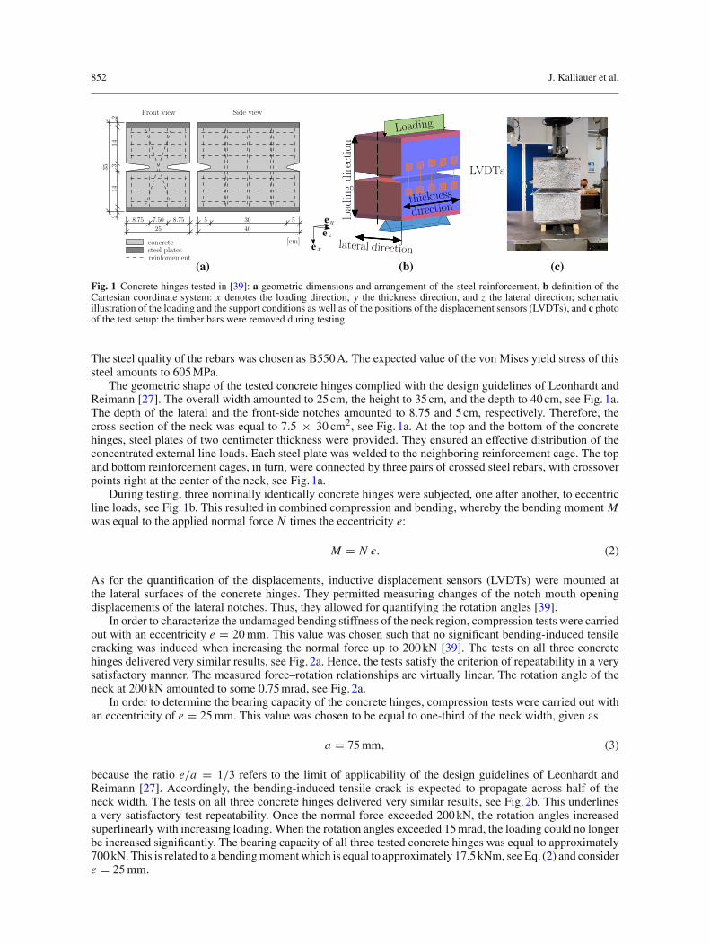
Fig. 1 Concrete hinges tested in [39]: a geometric dimensions and arrangement of the steel reinforcement, b definition of theCartesian coordinate system: x denotes the loading direction, y the thickness direction, and z the lateral direction; schematicillustration of the loading and the support conditions as well as of the positions of the displacement sensors (LVDTs), and c photoof the test setup: the timber bars were removed during testing
The steel quality of the rebars was chosen as B550A. The expected value of the von Mises yield stress of thissteel amounts to 605MPa.
The geometric shape of the tested concrete hinges complied with the design guidelines of Leonhardt andReimann [27]. The overall width amounted to 25cm, the height to 35cm, and the depth to 40cm, see Fig. 1a.The depth of the lateral and the front-side notches amounted to 8.75 and 5cm, respectively. Therefore, thecross section of the neck was equal to 7.5 × 30 cm2, see Fig. 1a. At the top and the bottom of the concretehinges, steel plates of two centimeter thickness were provided. They ensured an effective distribution of theconcentrated external line loads. Each steel plate was welded to the neighboring reinforcement cage. The topand bottom reinforcement cages, in turn, were connected by three pairs of crossed steel rebars, with crossoverpoints right at the center of the neck, see Fig. 1a.
During testing, three nominally identically concrete hinges were subjected, one after another, to eccentricline loads, see Fig. 1b. This resulted in combined compression and bending, whereby the bending moment Mwas equal to the applied normal force N times the eccentricity e:
M = N e. (2)
As for the quantification of the displacements, inductive displacement sensors (LVDTs) were mounted atthe lateral surfaces of the concrete hinges. They permitted measuring changes of the notch mouth openingdisplacements of the lateral notches. Thus, they allowed for quantifying the rotation angles [39].
In order to characterize the undamaged bending stiffness of the neck region, compression tests were carriedout with an eccentricity e = 20mm. This value was chosen such that no significant bending-induced tensilecracking was induced when increasing the normal force up to 200kN [39]. The tests on all three concretehinges delivered very similar results, see Fig. 2a. Hence, the tests satisfy the criterion of repeatability in a verysatisfactory manner. The measured force–rotation relationships are virtually linear. The rotation angle of theneck at 200kN amounted to some 0.75mrad, see Fig. 2a.
In order to determine the bearing capacity of the concrete hinges, compression tests were carried out withan eccentricity of e = 25mm. This value was chosen to be equal to one-third of the neck width, given as
a = 75mm, (3)
because the ratio e/a = 1/3 refers to the limit of applicability of the design guidelines of Leonhardt andReimann [27]. Accordingly, the bending-induced tensile crack is expected to propagate across half of theneck width. The tests on all three concrete hinges delivered very similar results, see Fig. 2b. This underlinesa very satisfactory test repeatability. Once the normal force exceeded 200kN, the rotation angles increasedsuperlinearly with increasing loading.When the rotation angles exceeded 15mrad, the loading could no longerbe increased significantly. The bearing capacity of all three tested concrete hinges was equal to approximately700kN. This is related to a bendingmomentwhich is equal to approximately 17.5kNm, see Eq. (2) and considere = 25mm.

Bearing capacity of concrete hinges 853
0 0.2 0.4 0.6 0.8rotation angle Δ [mrad]
0
50
100
150
200no
rmal
forc
eN
[kN
]experiments
0 5 10 15 20rotation angle Δ [mrad]
0
500
1000
1500
norm
alfo
rce
N[k
N]
experiments
(b)(a)ϕ ϕ
Fig. 2 Measured relations between the eccentric normal force N and the rotation angle Δϕ of three nominally identical concretehinges: a eccentricity e = 20mm, and b eccentricity e = 25mm; experimental data from [39]
3 FE simulations of the tested concrete hinges
Geometrically linear FE simulations are performed with version 5.1 of Atena science [8]. The FE simulationsare based on expected values of all material properties.
Inelastic material behavior of concrete is modeled based on two failure surfaces: (1) a Rankine surface forthe description of tension-induced failure, and (2) aMenétrey–Willam failure surface [7,8,33] for compression-induced failure. The latter is a function of the hydrostatic stress invariant, ξ , the deviatoric stress invariant, ρ,and the Lode angle, ϑ . It reads as
F p3P(ξ, ρ, ϑ) = 3
2
(ρ
f ′c
)2
+ m
f ′c
(ρr(ϑ)√
6+ ξ√
3
)− c ≤ 0, (4)
where m and r(ϑ), respectively, are defined as
m = 3 eσ
eσ + 1
f ′c2 − f ′
t2
f ′c f ′
t, (5)
and
r(ϑ) = 4 (1 − e2σ ) cos2 ϑ + (2 eσ − 1)2
2 (1 − e2σ ) cosϑ + (2 eσ − 1)√4 (1 − e2σ ) cos2 ϑ + 5 e2σ − 4 eσ
. (6)
In Eqs. (4)–(6), c denotes the hardening/softening parameter [8], with an initial value cini = 1, eσ standsfor the so-called eccentricity of the failure surface in deviatoric planes, with a default value eσ = 0.52, andf ′c denotes the evolving elastic limit stress of concrete under uniaxial compression. Notably, because of strain
hardening f ′c is allowed to increase from its initial value, fc0, up to the uniaxial compressive strength, fc.
Both fc0 and fc are input values for the material model. The symbol f ′t denotes the auxiliary uniaxial tensile
strength predicted by the Menétrey–Willam failure surface, while the actual uniaxial tensile strength, ft , withft < f ′
t , refers to the Rankine criterion. Notably, the definitions of ξ , ρ, and ϑ for a principle stress stateσ = σ1 ex ⊗ ex + σ2 ey ⊗ ey + σ3 ez ⊗ ez read as [17,33]
ξ = σ1 + σ2 + σ3√3
, (7)
ρ =√1
3
[(σ1 − σ2)2 + (σ2 − σ3)2 + (σ3 − σ1)2
], (8)
ϑ = 1
3arccos
⎛⎜⎝ (σ1 + σ2 − 2σ3)(2σ1 − σ2 − σ3)(σ1 − 2σ2 + σ3)
2[σ 21 − σ1 (σ2 + σ3) + σ 2
2 − σ2 σ3 + σ 23
]3/2⎞⎟⎠. (9)
854 J. Kalliauer et al.
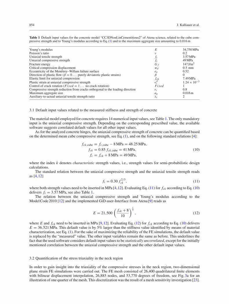
Table 1 Default input values for the concrete model “CC3DNonLinCementitious2” of Atena science, related to the cube com-pressive strength and to Young’s modulus according to Eq. (1) and to the maximum aggregate size amounting to 0.016m
Young’s modulus E 34,750MPaPoisson’s ratio ν 0.2Uniaxial tensile strength ft 3.57MPaUniaxial compressive strength fc 49MPaFracture energy G f 147J/m2
Critical compression displacement wd 0.5 mmEccentricity of the Menétrey–Willam failure surface eσ 0.52Direction of plastic flow (β = 0 . . . purely deviatoric plastic strains) β 0Elastic limit for uniaxial compression fc0 7.49MPaPlastic strain at uniaxial compressive strength ε
pc 1.24 × 10⁻³
Control of crack rotation (Fixed = 1 . . . no crack rotation) Fixed 1Compressive strength reduction from cracks orthogonal to the loading direction rc 0.8Maximum aggregate size ag 0.016mAuxiliary-to-actual uniaxial tensile strength ratio λt 2
3.1 Default input values related to the measured stiffness and strength of concrete
Thematerial model employed for concrete requires 14 numerical input values, see Table 1. The onlymandatoryinput is the uniaxial compressive strength. Depending on the corresponding prescribed value, the availablesoftware suggests correlated default values for all other input values.
As for the analyzed concrete hinges, the uniaxial compressive strength of concrete can be quantified basedon the determined mean cube compressive strength, see Eq. (1), and on the following standard relations [4]:
fck,cube = fc,cube − 8MPa = 48.25MPa,
fck = 0.85 fck,cube = 41MPa, (10)
fc = fck + 8MPa = 49MPa,
where the index k denotes characteristic strength values, i.e., strength values for semi-probabilistic designcalculations.
The standard relation between the uniaxial compressive strength and the uniaxial tensile strength readsas [4,12]
ft = 0.30 f 2/3ck , (11)
where both strength values need to be inserted in MPa [4,12]. Evaluating Eq. (11) for fck according to Eq. (10)delivers ft = 3.57MPa, see also Table 1.
The relation between the uniaxial compressive strength and Young’s modulus according to theModelCode2010 [12] and the implemented GiD-user-Interface from Atena [9] reads as
E = 21,500
(fck + 8
10
) 13
, (12)
where E and fck need to be inserted in MPa [9,12]. Evaluating Eq. (12) for fck according to Eq. (10) deliversE = 36,521MPa. This default value is by 5% larger than the stiffness value identified by means of materialcharacterization, see Eq. (1). For the sake of maximizing the reliability of the FE simulations, the default valueis replaced by the “measured” value. The other input variables remain the same as before. This underlines thefact that the used software considers default input values to be statistically uncorrelated, except for the initiallymentioned correlation between the uniaxial compressive strength and the other default input values.
3.2 Quantification of the stress triaxiality in the neck region
In order to gain insight into the triaxiality of the compressive stresses in the neck region, two-dimensionalplane strain FE simulations were carried out. The FE mesh consisted of 26,400 quadrilateral finite elementswith bilinear displacement interpolation, 26,885 nodes, and 53,770 degrees of freedom, see Fig. 3a for anillustration of one quarter of themesh. This discretization was the result of amesh sensitivity investigation [23].
Bearing capacity of concrete hinges 855
7.5 cmneck width
(a)
(b)
-200
-150
-100
-50
0
(c)
-200
-150
-100
-50
0
(d)
-4 -2 0 2 4
-4 -2 0 2 4
-4 -2 0 2 4
-200
-150
-100
-50
0
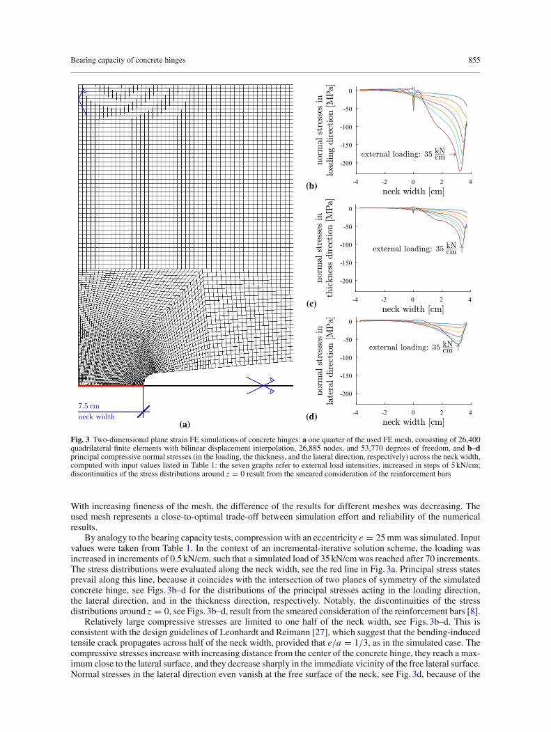
Fig. 3 Two-dimensional plane strain FE simulations of concrete hinges: a one quarter of the used FE mesh, consisting of 26,400quadrilateral finite elements with bilinear displacement interpolation, 26,885 nodes, and 53,770 degrees of freedom, and b–dprincipal compressive normal stresses (in the loading, the thickness, and the lateral direction, respectively) across the neck width,computed with input values listed in Table 1: the seven graphs refer to external load intensities, increased in steps of 5kN/cm;discontinuities of the stress distributions around z = 0 result from the smeared consideration of the reinforcement bars
With increasing fineness of the mesh, the difference of the results for different meshes was decreasing. Theused mesh represents a close-to-optimal trade-off between simulation effort and reliability of the numericalresults.
By analogy to the bearing capacity tests, compression with an eccentricity e = 25mmwas simulated. Inputvalues were taken from Table 1. In the context of an incremental-iterative solution scheme, the loading wasincreased in increments of 0.5kN/cm, such that a simulated load of 35kN/cmwas reached after 70 increments.The stress distributions were evaluated along the neck width, see the red line in Fig. 3a. Principal stress statesprevail along this line, because it coincides with the intersection of two planes of symmetry of the simulatedconcrete hinge, see Figs. 3b–d for the distributions of the principal stresses acting in the loading direction,the lateral direction, and in the thickness direction, respectively. Notably, the discontinuities of the stressdistributions around z = 0, see Figs. 3b–d, result from the smeared consideration of the reinforcement bars [8].
Relatively large compressive stresses are limited to one half of the neck width, see Figs. 3b–d. This isconsistent with the design guidelines of Leonhardt and Reimann [27], which suggest that the bending-inducedtensile crack propagates across half of the neck width, provided that e/a = 1/3, as in the simulated case. Thecompressive stresses increase with increasing distance from the center of the concrete hinge, they reach a max-imum close to the lateral surface, and they decrease sharply in the immediate vicinity of the free lateral surface.Normal stresses in the lateral direction even vanish at the free surface of the neck, see Fig. 3d, because of the

856 J. Kalliauer et al.
Fig. 4 Three-dimensional FE mesh of one-fourth of the investigated concrete hinges: the mesh consists of 27776 hexahedralfinite elements with trilinear displacement interpolation, 31730 nodes, and 95190 degrees of freedom. a Thickness direction, blateral direction
traction-free boundary condition prevailing there. At an external load intensity of 35kN/cm, the distribution ofthe compressive stresses, acting in the loading direction, is somewhat reminiscent of a triangular distribution,see Fig. 3a, such as considered by the design guidelines of Leonhardt and Reimann [27]. The largest compres-sive normal stresses, obtained for an external load intensity of 35kN/cm, amount to 224, 104, and 64MPa, in theloading direction, the thickness direction, and in the lateral direction, respectively, see Figs. 3b–d. This under-lines that concrete is subjected to significant triaxial compression in the neck region. The characteristic principalstress ratios amount to 1.00 : 0.45 : 0.30, and the characteristic triaxial compressive stress state σ reads as
σ = σ� · [1.00 ex ⊗ ex + 0.45 ey ⊗ ey + 0.30 ez ⊗ ez], (13)
where σ� denotes the principal compressive normal stress in the loading direction. The isotropic (“hydrostatic”)part of the stress state amounts to almost 60% of σ�. This confinement results in a significant strengthening ofconcrete, relative to its uniaxial compressive strength.
3.3 Three-dimensional FE simulations of eccentric compression tests
As for three-dimensional FE simulations of eccentric compression tests, the double symmetry of the problemallows for discretizing only one-fourth of the structure (Fig. 4). The used FE mesh consists of 27,776 hexahe-dral elements with trilinear displacement interpolation, 31,730 nodes, and 95,190 degrees of freedom (Fig. 4).This mesh was the result of a study regarding discretization errors. It represents a close-to-optimum trade-offbetween simulation effort and reliability of simulation results [23].
The simulations of the tests with the eccentricity e = 20mm are based on the input values listed in Table 1.The obtained numerical results reproduce the experimental observations in a qualitatively satisfactory fashion.The rotation angle increases almost linearly with increasing load, see the black graph in Fig. 5a. However, thestiffness of the undamaged concrete hinge is overestimated by some 40%.
The simulations of the bearing capacity tests with the eccentricity e = 25mm are based on the input valueslisted in Table 1. The obtained numerical results again reproduce the experimental observations in a qualita-tively satisfactory fashion. The rotation angle increases first linearly and later superlinearly with increasingload, see the black graph in Fig. 5b. However, the initial stiffness and the bearing capacity are overestimatedby some 40 and 80%, respectively.
The described quantitative differences between simulation results and experimental measurements under-line that default FE input, quantified on the basis of the measured stiffness and strength of concrete, overes-timates both the structural stiffness and the bearing capacity. This indicates that the concrete was damagedalready before the tests.
Bearing capacity of concrete hinges 857
0 0.2 0.4 0.6 0.8rotation angle Δ [mrad]
0
50
100
150
200no
rmal
forc
eN
[kN
]
FE simulationsexperiments
0 5 10 15 20rotation angle Δ [mrad]
0
500
1000
1500
norm
alfo
rce
N[k
N]
FE simulationexperiments
(a) (b)ϕ ϕ
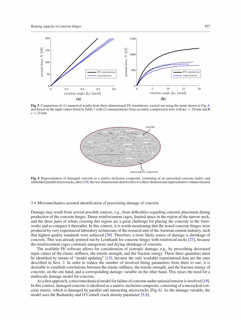
Fig. 5 Comparison of (1) numerical results from three-dimensional FE simulations, carried out using the mesh shown in Fig.4,and based on the input values listed in Table 1 with (2) measurements from eccentric compression tests with a e = 20mm and be = 25mm
cracks
uncracked concrete
Fig. 6 Representation of damaged concrete as a matrix–inclusion composite, consisting of an uncracked concrete matrix andembedded parallelmicrocracks, after [19]; the two-dimensional sketch refers to a three-dimensional representative volume element
3.4 Micromechanics-assisted identification of preexisting damage of concrete
Damage may result from several possible sources, e.g., from difficulties regarding concrete placement duringproduction of the concrete hinges. Dense reinforcement cages, limited space in the region of the narrow neck,and the three pairs of rebars crossing this region are a great challenge for placing the concrete in the form-works and to compact it thereafter. In this context, it is worth mentioning that the tested concrete hinges wereproduced by very experienced laboratory technicians of the research unit of the Austrian cement industry, suchthat highest quality standards were achieved [39]. Therefore, a more likely source of damage is shrinkage ofconcrete. This was already pointed out by Leonhardt for concrete hinges with reinforced necks [27], becausethe reinforcement cages constrain autogenous and drying shrinkage of concrete.
The available FE software allows for consideration of isotropic damage, e.g., by prescribing decreasedinput values of the elastic stiffness, the tensile strength, and the fracture energy. These three quantities mustbe identified by means of “model updating” [15], because the only available experimental data are the onesdescribed in Sect. 2. In order to reduce the number of involved fitting parameters from three to one, it isdesirable to establish correlations between the elastic stiffness, the tensile strength, and the fracture energy ofconcrete, on the one hand, and a corresponding damage variable on the other hand. This raises the need for amultiscale damage model for concrete.
As a first approach, amicromechanical model for failure of concrete under uniaxial tension is involved [19].In this context, damaged concrete is idealized as a matrix–inclusion composite, consisting of a uncracked con-crete matrix, which is damaged by parallel and interacting microcracks (Fig. 6). As the damage variable, themodel uses the Budiansky and O’Connell crack density parameter [5,6].
858 J. Kalliauer et al.
Young’s modulus of damaged concrete in the direction normal to the crack planes, Ec,dam, decreases withincreasing crack density ω. The corresponding mathematical relation follows from a Mori-Tanaka stiffnessestimate [2,35,41]. It reads as [19]
Ec,dam = Ec
[1 + 16ω
3
(1 − ν2
)]−1
, (14)
where Ec, ν, and ω denote Young’s modulus, Poisson’s ratio of uncracked concrete, and the crack densityparameter.
The tensile strength of damaged concrete, ft,dam, decreases with increasing crack density ω. The corre-spondingmathematical relationwas derived in the framework of combinedmicro-fracture-mechanics approachfrom direct tension tests on dog-bone-shaped concrete specimens [19]. It reads as
ft,dam = 0.9425 ft√ω + 0.8177
. (15)
Equations (14) and (15) establish a correlation between Young’s modulus and the tensile strength of damagedconcrete, by means of the damage variable ω.
The fracture energy of damaged concrete, G f,dam, decreases with increasing crack density ω. In moredetail, G f,dam is equal to the difference of the fracture energy of uncracked concrete, see G f in Table 1, andthe increment ΔG f of the damage-related energy dissipation:
G f,dam = G f − ΔG f . (16)
In the available FE software, tensile softening is modeled on the basis of a smeared crack approach. Therefore,ΔG f follows as the work produced by the cohesive tensile strength, σ , along the crack opening of the smearedcrack, w, i.e.,
ΔG f =∫
σ dw. (17)
In the available FE software the mathematical relation between σ and w is considered according to the modelby Hordijk [20]. It reads as
σ
ft=
[1 +
(c1
w
wc
)3 ]exp
(−c2
w
wc
)− w
wc
(1 + c1
3) exp (−c2) , (18)
with
c1 = 3, c2 = 6.93, wc = 5.14G f
ft, (19)
see also Fig. 7. Quantification of ΔG f requires an expression for the crack opening displacement w as afunction of the damage variable ω. To this end, Eq. (18) is specialized for Eq. (19), σ = ft,dam, with ft,damaccording to Eq. (15), and for numerical values of G f and ft , taken from Table 1. After rearranging terms, thefollowing nonlinear expression for wdam as a function of ω is obtained
wdam − 2.201 · 1010 w3dam + 3.511 · 10−13
exp (3.274 · 104 · wdam)= −6.989 · 10−3
√ω + 8.177 · 10−1
. (20)
Equation (20) is solved numerically for given values of the damage variable ω. The energy, dissipated duringdamage-related cracking, is equal to the area under the softening curve, see the shaded area in Fig. 7b. It followsfrom Eqs. (17)–(20) as
ΔG f = ft
∫ wdam
0
{[1 + 27
(w
wc
)3 ]exp
(−6.93
w
wc
)− 28
w
wcexp (−6.93)
}dw. (21)
Preexisting damage of concrete is identified by means of correlated structural sensitivity analyses. Threedifferent damage levels are investigated: 3, 6, and 9%. For each of these damage levels, corresponding FEinput values regarding Young’s modulus, the tensile strength, and the fracture energy of concrete are computedaccording to Eqs. (14)–(21), see also Table 2. The elastic stiffness decreases significantly with increasing dam-age, while the tensile strength and the fracture energy decrease only slightly. Anyway, the newly computed
Bearing capacity of concrete hinges 859
0 0.2 0.4 0.6 0.8 10
0.2
0.4
0.6
0.8
1
0 0.02 0.04 0.06 0.08 0.10
0.2
0.4
0.6
0.8
1
(b)(a)
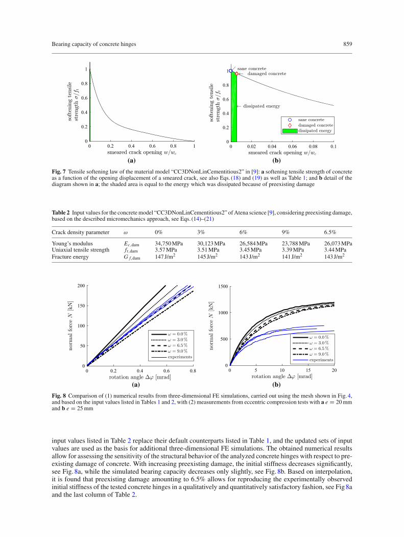
Fig. 7 Tensile softening law of the material model “CC3DNonLinCementitious2” in [9]: a softening tensile strength of concreteas a function of the opening displacement of a smeared crack, see also Eqs. (18) and (19) as well as Table 1; and b detail of thediagram shown in a; the shaded area is equal to the energy which was dissipated because of preexisting damage
Table 2 Input values for the concretemodel “CC3DNonLinCementitious2” of Atena science [9], considering preexisting damage,based on the described micromechanics approach, see Eqs. (14)–(21)
Crack density parameter ω 0% 3% 6% 9% 6.5%
Young’s modulus Ec,dam 34,750MPa 30,123MPa 26,584MPa 23,788MPa 26,073MPaUniaxial tensile strength ft,dam 3.57MPa 3.51MPa 3.45MPa 3.39MPa 3.44MPaFracture energy G f,dam 147J/m2 145J/m2 143J/m2 141J/m2 143J/m2
0 0.2 0.4 0.6 0.8rotation angle Δ [mrad]
0
50
100
150
200
norm
alfo
rce
N[k
N]
ω = 0.0 %ω = 3.0 %ω = 6.5 %ω = 9.0 %experiments
0 5 10 15 20rotation angle Δ [mrad]
0
500
1000
1500
norm
alfo
rce
N[k
N]
ω = 0.0 %ω = 3.0 %ω = 6.5 %ω = 9.0 %experiments
(a) (b)ϕ ϕ
Fig. 8 Comparison of (1) numerical results from three-dimensional FE simulations, carried out using the mesh shown in Fig.4,and based on the input values listed in Tables 1 and 2, with (2) measurements from eccentric compression tests with a e = 20mmand b e = 25mm
input values listed in Table 2 replace their default counterparts listed in Table 1, and the updated sets of inputvalues are used as the basis for additional three-dimensional FE simulations. The obtained numerical resultsallow for assessing the sensitivity of the structural behavior of the analyzed concrete hinges with respect to pre-existing damage of concrete. With increasing preexisting damage, the initial stiffness decreases significantly,see Fig. 8a, while the simulated bearing capacity decreases only slightly, see Fig. 8b. Based on interpolation,it is found that preexisting damage amounting to 6.5% allows for reproducing the experimentally observedinitial stiffness of the tested concrete hinges in a qualitatively and quantitatively satisfactory fashion, see Fig8aand the last column of Table 2.

860 J. Kalliauer et al.
Table 3 Triaxial-to-uniaxial compressive strength ratio, σ�u/ fc, predicted by the Menétrey–Willam failure surface, see Eqs. (4)–(6), for the characteristic triaxial compressive stress state (13), see also Eq. (23), for input values listed in Tables 1 and 2 (seeinput referring to ω = 6.5%), and for different values of the auxiliary-to-actual uniaxial tensile strength ratio λt
λt 2.00 4.00 6.00 8.00 8.50σ�u/ fc 5.65 3.20 2.44 2.07 2.00
-8 -6 -4 -2 00
1
2
3
4
Fig. 9 Menétrey–Willam failure meridians illustrated in a section through the principal stress space containing the hydrostaticaxis: Eqs. (4)–(6) evaluated for Lode angle ϑ = 0.84 and input values listed in Tables 1 and 2 (see input referring to ω = 6.5%)as well as for auxiliary-to-actual uniaxial tensile strength ratios λt ∈ [ 2 , 4 , 6 , 8 ]; the shown meridian and the stress path (bluegraph) refer to the characteristic triaxial stress state (13), see also Eq. (23)
3.5 Sensitivity analysis regarding the triaxial strength of concrete
In order to reproduce also the bearing capacity reliably, it is necessary to reduce the triaxial compressivestrength of concrete. Notably, this modification shall neither change the uniaxial compressive strength nor theupdated uniaxial tensile strength. This can be achieved by increasing the input parameter λt , which quantifiesthe ratio between the auxiliary uniaxial tensile strength f ′
t of the Menétrey–Willam failure surface and theactual uniaxial tensile strength ft of the Rankine failure surface:
λt = f ′t
ft, (22)
where λt = 2 is the corresponding default input value, see Table 1.The starting point for the corresponding sensitivity analysis is the investigation of the characteristic triaxial
compressive stress state σ of the investigated concrete hinges, see Eq. (13). The hydrostatic and deviatoricstress invariants as well as the Lode angle of this stress state read, according to Eqs. (7)–(9), as
ξ = 1.010 σ�, ρ = 0.521 |σ�|, ϑ = 0.84. (23)
Based on the default input parameterλt = 2, see Table 1, theMenétrey–Willam failure surface, see Eqs. (4)–(6),suggests that the triaxial strength σ�u is equal to 5.65 times the uniaxial compressive strength.
Increasing, in the framework of a sensitivity analysis, the input parameter λt from 2 via 4 and 6 to 8, deliversMenétrey–Willam failure surfaces with decreasing slopes in the ξ–ρ diagrams, see Fig. 9. The correspondingvalues of the triaxial-to-uniaxial compressive strength ratio, σ�u/ fc, decrease from 5.65 via 3.20 and 2.44 to2.07, see also Table 3.
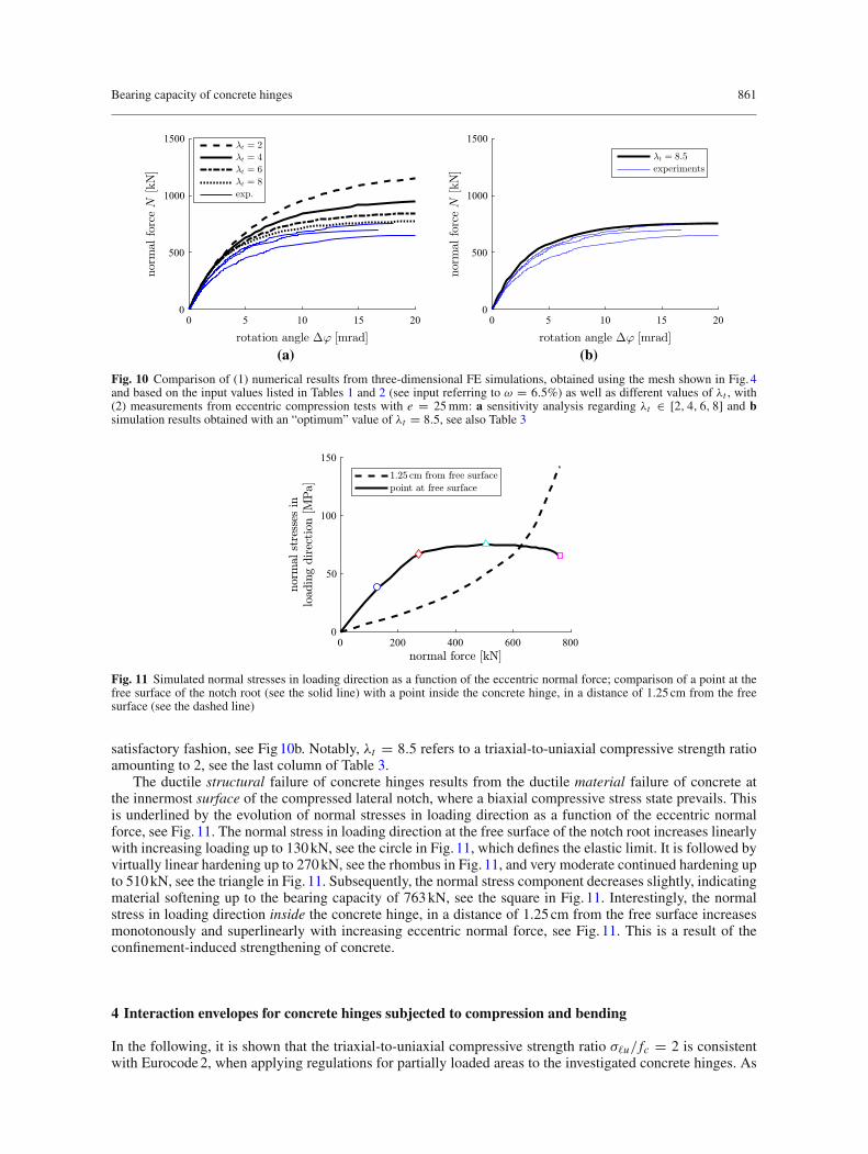
As for further improved FE analyses of concrete hinges, the described modification of theMenétrey–Willam failure surface is carried out. Apart from that, default input values from Table 1 are used,except for Young’s modulus, the tensile strength, and the fracture energy which are taken from the columnwith headline ω = 6.5% of Table 2. Increasing the input parameter λt from 2 via 4 to 6 and 8, respectively,delivers simulation results, characterized by the same initial stiffness, but by progressively decreasing ultimatebearing capacities, see Fig. 10a. Based on extrapolation, it is found that λt = 8.5 allows for reproducing theexperimentally obtained bearing capacity of the tested concrete hinges in a qualitatively and quantitatively
Bearing capacity of concrete hinges 861
0 5 10 15 20
rotation angle Δ [mrad]
0
500
1000
1500no
rmal
forc
eN
[kN
]λt = 2λt = 4λt = 6λt = 8exp.
0 5 10 15 20
rotation angle Δ [mrad]
0
500
1000
1500
norm
alfo
rce
N[k
N]
λt = 8.5experiments
(b)(a)ϕ ϕ
Fig. 10 Comparison of (1) numerical results from three-dimensional FE simulations, obtained using the mesh shown in Fig.4and based on the input values listed in Tables 1 and 2 (see input referring to ω = 6.5%) as well as different values of λt , with(2) measurements from eccentric compression tests with e = 25mm: a sensitivity analysis regarding λt ∈ [2, 4, 6, 8] and bsimulation results obtained with an “optimum” value of λt = 8.5, see also Table 3
0 200 400 600 8000
50
100
150
Fig. 11 Simulated normal stresses in loading direction as a function of the eccentric normal force; comparison of a point at thefree surface of the notch root (see the solid line) with a point inside the concrete hinge, in a distance of 1.25cm from the freesurface (see the dashed line)
satisfactory fashion, see Fig10b. Notably, λt = 8.5 refers to a triaxial-to-uniaxial compressive strength ratioamounting to 2, see the last column of Table 3.
The ductile structural failure of concrete hinges results from the ductile material failure of concrete atthe innermost surface of the compressed lateral notch, where a biaxial compressive stress state prevails. Thisis underlined by the evolution of normal stresses in loading direction as a function of the eccentric normalforce, see Fig. 11. The normal stress in loading direction at the free surface of the notch root increases linearlywith increasing loading up to 130kN, see the circle in Fig. 11, which defines the elastic limit. It is followed byvirtually linear hardening up to 270kN, see the rhombus in Fig. 11, and very moderate continued hardening upto 510kN, see the triangle in Fig. 11. Subsequently, the normal stress component decreases slightly, indicatingmaterial softening up to the bearing capacity of 763kN, see the square in Fig. 11. Interestingly, the normalstress in loading direction inside the concrete hinge, in a distance of 1.25cm from the free surface increasesmonotonously and superlinearly with increasing eccentric normal force, see Fig. 11. This is a result of theconfinement-induced strengthening of concrete.
4 Interaction envelopes for concrete hinges subjected to compression and bending
In the following, it is shown that the triaxial-to-uniaxial compressive strength ratio σ�u/ fc = 2 is consistentwith Eurocode2, when applying regulations for partially loaded areas to the investigated concrete hinges. As

862 J. Kalliauer et al.
(b)(a)
Fig. 12 Application of the regulations of Eurocode2 regarding partially loaded areas [4] to concrete hinges: a geometric dimen-sions, and b stress distribution in the uncracked ligament of the neck
for a partially loaded area (Fig. 12), Eurocode 2 allows a maximum compressive force FRdu which readsas [4]
FRdu = Aco fcd
√Ac1
Ac0, (24)
where Ac0 = d1 b1 is the loaded area, fcd denotes the uniaxial compressive strength, and Ac1 = d2 b2 stands forthe “maximum distribution area with a similar shape to Ac0” [4]. Eq. (24) suggests that the triaxial-to-uniaxialstrength ratio amounts to
√Ac1/Ac0.
Applying Eq. (24) to the herein investigated concrete hinges, Ac0 is equal to the uncracked area of the neck,such that d1 = 30 cm is the length of the neck in the thickness direction, b1 is the length of the uncracked neckligament in the lateral direction, see Fig. 12a, d2 = 40 cm is the length of the concrete hinge in the thicknessdirection, and b2 = 3 b1 [4]. Specifying the triaxial-to-uniaxial compressive strength ratio for these geometricproperties, delivers √
Ac1
Ac0=
√3 b1 · 40b1 · 30 = 2. (25)
Interestingly, this is equal to the triaxial-to-uniaxial compressive strength ratio which was identified in Sect. 3,see the last column of Table 3.
In order to derive a Eurocode-inspired interaction envelope for concrete hinges subjected to compressionand bending, the length b1 of the uncracked neck ligament is used as a parameter. Considering that compressivenormal stresses in the loading direction, amounting to 2 fc, prevail along the uncracked ligament b1 of concrete,see Fig. 12b, the resulting normal force reads as
N = 2 fc b1 d1. (26)
This normal force has an eccentricity e = (a − b1) /2 with respect to the midplane of the concrete hinge, seeFig. 12b. Therefore, the resulting bending moment reads as [43]
M = Na − b1
2= fc b1 d1 (a − b1). (27)
The interaction envelope is obtained by solving Eq. (26) for the parameter b1 and using the resulting expressionto eliminate the parameter b1 from Eq. (27):
M = N
2
(a − N
2 fc d1
), (28)
where a = 75mm, fc = 49MPa, and d1 = 300mm. The failure envelope (28) agrees very well with theexperimentally determined bearing capacities for eccentric compression, see Fig. 13.

Bearing capacity of concrete hinges 863
0 5 10 15 20 250
500
1000
1500
2000
2500
Fig. 13 Eurocode-inspired failure envelope for concrete hinges subjected to compression and bending according to Eq. (28) andcomparison with the bearing capacity tests reported in [39], see also Fig. 2b
5 Discussion
The bearing capacity of concrete hinges subjected to eccentric compressionwas re-analyzed bymeans of three-dimensional FE analyses. Numerical results provide insight into the functionality of concrete hinges. The fol-lowing discussion focuses (1) on the triaxial stress states prevailing in the compressed part of the neck region and(2) on the mechanisms that enable a failure of concrete hinges in the experimentally observed ductile fashion.
FE simulations allowed for quantifying the triaxial compressive stress states prevailing in the neck region ofthe analyzed concrete hinges.Notably, the compressive normal stresses in the lateral and the thickness directionsresult from stress trajectories that must run around the notches. The inclination angles of the stress trajectoriescreate the desired compressive stresses, orthogonal to the loading direction. While this underlines the impor-tance of front-side notches, it is also interesting to note that the characteristic principal compressive stress ratiowas quantified as 1.00 : 0.45 : 0.30. Such a pronounced stress triaxiality implies the existence of an isotropicstress part which amounts to almost 60% of the principal stress acting in loading direction. This confine-ment pressure results in a considerable increase of the strength of concrete relative to its uniaxial compressivestrength. Superficially, this explains the impressive bearing capacity of concrete hinges. Inmore depth, however,it is important to realize that a three-axial stress state is impossible at the free surface in the innermost regionof the compressed lateral neck, because of the traction-free boundary condition prevailing at this neck root.
A plane stress state prevails at the air-exposed neck root. In this context, it is noteworthy that the biaxialcompressive strength of concrete is only a few percent larger than the uniaxial compressive strength of thematerial [25]. Consequently, the strength of concrete at the surface of the neck root is reached already atexternal load intensities that are significantly smaller than the bearing capacity of the concrete hinge. Still,both the experiments and the numerical simulations show that there is no spalling of the failing surface layerat the neck root. More importantly, the stress state does not decrease significantly, see Fig. 11, although thestrains do increase considerably. In other words, the surface layer exhibits a ductile rather than a brittle failurebehavior. The continued integrity of the surface layer at the neck root, in turn, is essential for the built-upof the triaxial compressive stress state behind the surface layer. If the surface layer would spall away, theneighboring layer, which initially was inside the volume of the structure, would become the new surface layer.Consequently, the initially triaxial stress state would transform all over sudden into a biaxial stress state suchthat the strength of the material would drop from the large strength under confined triaxial compression to themuch smaller strength under biaxial compression. This renders it likely that initiation of spalling at the surfaceof the neck root would result in a catastrophic domino effect. A spalling front would propagate quickly in thedirection toward the center of the concrete hinge. Anyway, there is plenty of evidence from testing of concretehinges and from practical applications that spalling does not take place as long as the loading is not close tothe bearing capacity of the concrete hinges. This underlines that the ductile failure behavior of concrete underbiaxial compression at the surface of the neck root is the mechanism which makes it possible that concretehinges fail in the experimentally observed ductile fashion.

864 J. Kalliauer et al.
6 Conclusions
Testing provides very valuable insight into the structural performance of concrete hinges. However, availabledeformation and displacement measurements are typically limited to the easily accessible surface of concretehinges. In order to gain insight into what is happening inside the volume of concrete hinges, FE simulationsare indispensable. Herein, they allowed for quantifying the triaxial compressive stress states prevailing in theneck region and the mechanism which makes it possible for concrete hinges to fail in a ductile fashion. Fromthe presented study, the following conclusions are drawn:
– As for the investigated concrete hinges, the triaxial compressive stress state in the neck region exhibits acharacteristic ratio of the principal stresses in the loading direction, the thickness direction, and the lateraldirection, amounting to 1.00 : 0.45 : 0.30.
– This stress triaxiality is a consequence of the notches, because the stress trajectories must run around them.The inclination angles of the stress trajectories create the desired compressive stresses, orthogonal to theloading direction. This underlines the importance of front-side notches.
– The ratio of principal compressive stresses, 1.00 : 0.45 : 0.30, implies that the isotropic part of the stressstate amounts to almost 60% of the compressive stresses in the loading direction. This significant confine-ment pressure results in a considerable strengthening of the concrete, relative to its uniaxial compressivestrength.
– Herein, the strengthening factor was identified to amount to 2. This is consistent with Eurocode regulationsfor partially loaded areas of concrete.
– Quantifying the triaxial strength of concrete on the basis of Eurocode regulations for partially loadedareas allows for (1) simulating realistic bearing capacities of concrete hinges in the context of numericalmultiscale structural analysis, and (2) deriving reasonable failure envelopes for concrete hinges subjectedto compression and bending.
– The ductile structural failuremode of concrete hinges results from the ductilematerial failure of concrete atthe innermost surface of the compressed lateral notch,where a biaxial compressive stress state prevails. Thisductile material failure enables (1) the built-up of triaxial stress states inside the volume of concrete hinges,and (2) remarkably large bearing capacities of concrete hinges subjected to compression and bending.
Acknowledgements Open access funding provided byAustrian Science Fund (FWF). Financial support by theAustrianMinistryfor Transport and Technology (bmvit), the Austrian Research Promotion Agency (FFG), ÖBB-Infrastruktur AG, ASFINAG BauManagement GmbH, provided within the VIF-project 845681 “Optimierte Bemessungsregeln für dauerhafte bewehrte Betonge-lenke” and corresponding discussions withMichael Schweigler (TUWien), Susanne Gmainer andMartin Peyerl (Smart MineralsGmbH), Alfred Hüngsberg (ÖBB-Infrastruktur AG), Erwin Pilch and Michael Kleiser (ASFINAG Bau Management GmbH) aregratefully acknowledged. Additional interesting discussions regarding the use of concrete hinges inmechanized tunneling, carriedout within the Austrian Science Fund (FWF) project P 281 31-N32 “Bridging the Gap bymeans ofMultiscale Structural Analysis”with Yong Yuan (Tongji University) and Jiaolong Zhang (TU Wien/Tongji University) are also gratefully acknowledged.
Compliance with ethical standards
Conflict of interest The authors declare that they have no conflict of interest.
Open Access This article is distributed under the terms of the Creative Commons Attribution 4.0 International License (http://creativecommons.org/licenses/by/4.0/), which permits unrestricted use, distribution, and reproduction in any medium, providedyou give appropriate credit to the original author(s) and the source, provide a link to the Creative Commons license, and indicateif changes were made.
References
1. Austrian Standards Institute: ONR 23303:2010-09-01 Prüfverfahren Beton (PVB)—Nationale Anwendung der Prüfnormenfür Beton und seiner Ausgangsstoffe [Test protocol concrete - National application of testing standards for concrete and itsraw materials], vol. ONR 23303. Austrian Standards Institute (2010) (in German)
2. Benveniste, Y.: A new approach to the application of Mori–Tanaka’s theory in composite materials. Mech. Mater. 6(2),147–157 (1987). https://doi.org/10.1016/0167-6636(87)90005-6
3. Blom, C.B.M.: Design philosophy of concrete linings for tunnels in soft soils. Doctoral dissertation, Delft University ofTechnology (2002)
4. British Standards Institution, CEN European Committee for Standardization: EN 1992-1-1:2015-07-31 Eurocode 2: designof concrete structures—part 1-1: general rules and rules for buildings (2015)
5. Budiansky, B.: On the elastic moduli of some heterogeneous materials. J. Mech. Phys. Solids 13(4), 223–227 (1965). https://doi.org/10.1016/0022-5096(65)90011-6
Bearing capacity of concrete hinges 865
6. Budiansky, B., O’Connell, R.J.: Elastic moduli of a cracked solid. Int. J. Solids Struct. 12(2), 81–97 (1976). https://doi.org/10.1016/0020-7683(76)90044-5
7. Cervenka, J., Papanikolaou, V.K.: Three dimensional combined fracture-plastic material model for concrete. Int. J. Plast.24(12), 2192–2220 (2008). https://doi.org/10.1016/j.ijplas.2008.01.004
8. Cervenka, V., Jendele, L., Cervenka, J.: ATENA program documentation part 1—theory, February 5, 2016 edn. http://www.cervenka.cz/assets/files/atena-pdf/ATENA_Theory.pdf (2016)
9. Cervenka Consulting, Cervenka, V., Jendele, L., Cervenka, J., et al.: Build 12562 & Atena 5.1.3. Internet source. http://www.cervenka.cz/download/#atena-gid (2016)
10. Chen, J., Mo, H.: Numerical study on crack problems in segments of shield tunnel using finite element method. Tunn.Undergr. Space Technol. 24(1), 91–102 (2009). https://doi.org/10.1016/j.tust.2008.05.007
11. De Waal, R.G.A.: Steel fibre reinforced tunnel segments: for the application in shield driven tunnel linings. Doctoral disser-tation, Delft University of Technology (2000)
12. fib: fib Model Code for Concrete Structures 2010. Ernst & Sohn, Wiley (2013). https://doi.org/10.1002/978343360409013. Freyssinet, E.: Le pont de Candelier [The bridge of Candelier]. Ann. Ponts Chaussées 1, 165f (1923)14. Freyssinet, E.: Naissance du béton précontraint et vues d’avenir [Birth of prestressed concrete and future outlook]. Travaux,
pp. 463–474 (1954)15. Friswell, M.I., Mottershead, J.E.: Finite Element model updating in structural dynamics, vol. 38. Springer (1995). https://
doi.org/10.1007/978-94-015-8508-816. Gladwell, G.M.: Contact problems in the classical theory of elasticity. Springer (1980). https://doi.org/10.1007/978-94-009-
9127-917. Grassl, P., Jirásek, M.: Damage-plastic model for concrete failure. Int. J. Solids Struct. 43(2223), 7166–7196 (2006). https://
doi.org/10.1016/j.ijsolstr.2006.06.03218. Hefny, A.M., Chua, H.C.: An investigation into the behaviour of jointed tunnel lining. Tunn. Underg. Space Technol. 21(34),
428 (2006). https://doi.org/10.1016/j.tust.2005.12.070. In: Safety in theUndergroundSpace—Proceedings of the ITA-AITES2006 World Tunnel Congress and 32nd ITA General Assembly
19. Hlobil, M., Göstl, M., Burrus, J., Hellmich, C., Pichler, B.: Molecular-to-macro upscaling of concrete fracture: theory andexperiments. J. Mech. Phys. Solids, under revision (2017)
20. Hordijk, D.A.: Local Approach to Fatigue of Concrete, vol. 210. Doctoral dissertation, Delft University of Technology, TheNetherlands (1991). ISBN 90/9004519-8
21. Janßen, P.: Tragverhalten von Tunnelausbautenmit Gelenkstübbings [Structural behavior of segmented tunnel linings]. Ph.D.thesis, Technical University of Braunschweig (1986)
22. Jusoh, S.N., Mohamad, H., Marto, A., Yunus, N.Z.M., Kasim, F.: Segment’s joint in precast tunnel lining design. J. Teknol.77(11), 91–98 (2015). https://doi.org/10.11113/jt.v77.6426
23. Kalliauer, J.: Insight into the structural behavior of concrete hinges by means of finite element simulations. Master thesis,TU Wien, Karslplatz 13, 1010 Wien (2016)
24. Klappers, C., Grübl, F., Ostermeier, B.: Structural analyses of segmental lining—coupled beam and spring analyses versus3D-FEM calculations with shell elements. Tunn. Undergr. Space Technol. 21(3–4), 254–255 (2006). https://doi.org/10.1016/j.tust.2005.12.116
25. Kupfer, H., Hilsdorf, H.K., Rusch, H.: Behavior of concrete under biaxial stresses. J. Proc. 66(8), 656–666 (1969)26. Leonhardt, F.: Mainbrücke Gemünden—Eisenbahnbrücke aus Spannbeton mit 135 m Spannweite [Bridge over the river
Main at Gemünden—prestressed railway bridge with a span of 135 m]. Beton Stahlbetonbau 81(1), 1–8 (1986). https://doi.org/10.1002/best.198600010
27. Leonhardt, F., Reimann, H.: Betongelenke: Versuchsbericht, Vorschläge zur Bemessung und konstruktiven Ausbildung.Kritische Spannungszustände des Betons bei mehrachsiger, ruhender Kurzzeitbelastung [Concrete hinges: test report, rec-ommendations for structural design. Critical stress states of concrete under multiaxial static short-term loading], vol. 175.Ernst und Sohn, Berlin (1965) (in German)
28. Maidl, B., Herrenknecht, M., Maidl, U., Wehrmeyer, G.: Mechanised Shield Tunnelling. Wiley-Blackwell (2012). https://doi.org/10.1002/9783433601051
29. Majdi, A., Ajamzadeh, H., Nadimi, S.: Investigation of moment–rotation relation in different joint types and evaluation oftheir effects on segmental tunnel lining. Arab. J. Geosci. 9(7), 1–15 (2016). https://doi.org/10.1007/s12517-016-2538-z
30. Marx, S., Schacht, G.: Betongelenke im Brückenbau [Concrete hinges in bridge construction], vol. 18. Deutscher Beton-und Bautechnik-Verein e.v. (2010) (in German)
31. Marx, S., Schacht, G.: Concrete hinges—historical development and contemporary use. 3rd fib International Congress, 2010,pp. 1–21 (2010)
32. Marx, S., Schacht, G.: Gelenke im Massivbau [Hinges in concrete structures]. Beton Stahlbetonbau 105(1), 27–35 (2010).https://doi.org/10.1002/best.200900061. (in German)
33. Menétrey, P., Willam, K.J.: Triaxial failure criterion for concrete and its generalization. ACI Struct. J. 92(3), 311–318 (1995).https://doi.org/10.14359/1132
34. Morgenthal, G., Olney, P.: Concrete hinges and integral bridge piers. J. Bridge Eng. 21(1), 06015,005 (2016). https://doi.org/10.1061/(ASCE)BE.1943-5592.0000783
35. Mori, T., Tanaka, K.: Average stress in matrix and average elastic energy of materials with misfitting inclusions. Acta Metall.21(5), 571–574 (1973). https://doi.org/10.1016/0001-6160(73)90064-3
36. Sallenbach, H.H: Betongelenke beimHardturm-Viadukt [Concrete hinges for the Hardturm-Viadukt]. Schweizer Bauzeitung85 (1967)
37. Schacht, G.,Marx, S.: Unbewehrte Betongelenke—100 Jahre Erfahrung imBrückenbau [Unreinforced concrete hinges—100years of experience in bridge construction]. Beton Stahlbetonbau 105(9), 599–607 (2010). (in German)
38. Schacht, G., Marx, S.: Concrete hinges in bridge engineering. Proc. Inst. Civ. Eng. Eng. Hist. Herit. 168(2), 65–75 (2015).https://doi.org/10.1680/ehah.14.00020

866 J. Kalliauer et al.
39. Schlappal, T., Schweigler, M., Gmainer, S., Peyerl, M., Pichler, B.: Creep and cracking of concrete hinges: insight fromcentric and eccentric compression experiments. Mater. Struct. 50(6), 244 (2017). https://doi.org/10.1617/s11527-017-1112-9
40. Teachavorasinskun, S., Chub-uppakarn, T.: Influence of segmental joints on tunnel lining. Tunn. Undergr. Space Technol.25(4), 490–494 (2010). https://doi.org/10.1016/j.tust.2010.02.003
41. Zaoui, A.: Continuum micromechanics: survey. J. Eng. Mech. 128(8), 808–816 (2002). https://doi.org/10.1061/(asce)0733-9399(2002)128:8(808)
42. Zhang, W., Jin, X., Yang, Z.: Combined equivalent & multi-scale simulation method for 3-D seismic analysis of large-scaleshield tunnel. Eng. Comput. 31(3), 584–620 (2014). https://doi.org/10.1108/EC-02-2012-0034
43. Ziegler, F.: Mechanics of solids and fluids, 2nd edn. Springer (1995). https://doi.org/10.1007/978-1-4612-0805-1