beauly-denny replacement transmission line project · 2014-11-13 · beauly-denny replacement...
TRANSCRIPT

Beauly-Denny Replacement Transmission Line
Project
APPENDIX 18 Temporary Access Track
Construction Methodology – Generic Guidance
Revision: 2
July 2013

Wharry Burn to Denny North Substation Temporary Access Track Construction Methodology – Generic Guidance
Revision 2 Date: July 2013
CONTENTS LIST
1 Introduction .................................................................................................................................... 1
1.1 Introduction ............................................................................................................................... 1 2 Access Track Route Design ......................................................................................................... 2
2.1 The Access Track Constraints Checklist .................................................................................. 2 3 Access Track Construction .......................................................................................................... 3
3.1 General ..................................................................................................................................... 3 3.2 Soil Management ...................................................................................................................... 3 3.3 Restoration of Grassland, Heath and Bog ................................................................................ 4 3.4 Engineering Parameters ........................................................................................................... 4 3.5 Track Construction Types ......................................................................................................... 6 3.6 Drainage ................................................................................................................................... 9
ANNEX A ACCESS TRACK CONSTRAINTS CHECKLIST

Wharry Burn to Denny North Substation Temporary Access Track Construction Methodology – Generic Guidance
Revision 2 1 Date: July 2013
1 Introduction
1.1 Introduction
1.1.1 There are three key stages in the process for determining the final positions of the overhead line infrastructure including the access tracks: Stage 1
1.1.2 To include a wide range of detailed desk studies, consultations and environmental and tech-nical field surveys to inform the routeing study and define the proposed route (including Limits of Deviation, LOD) which was assessed in the ES.
1.1.3 Unless otherwise agreed by SPEN/IEC, together with relevant consultees, all works associated with the overhead line including access tracks would be undertaken within the corridors defined by the LOD, taking account of the committed measures set out in the Mitigation Strategy. All committed mitigation measures have been used to form the basis of the Construction Proce-dures Handbook (CPH) developed by SPT and the project specialist environmental advisors, with input from contractors. Stage 2
1.1.4 Prior to construction beginning, further surveys would be initiated or updated within the corri-dors defined by the LODs to inform the design to ensure the delivery of the most effective level of environmental mitigation and help in micro-siting towers and access tracks. The level of re-quired survey at Stage 2 will vary according to the level of survey undertaken in Stage 1 but could include:
Breeding bird surveys Protected Species checks and additional surveys Archaeological survey Detailed ground investigations
Stage 3
1.1.5 The location of each tower site and access would be set out on site prior to construction beginning, informed by information in the CPH. In any location where particular sensitivities have been identified in Stages 1 and/or 2 and where it is considered by the project technical advisors that a particular expert should be on site to ensure that mitigation is fully implemented (for example to locate a track to avoid a badger sett or an archaeological site) (an) appropriate expert(s) will be on site to input their expertise if considered necessary. These requirements would be identified as part of the consultations at the end of Stage 2.
1.1.6 It is intended that this methodology would serve the following purposes: To form part of the CPH (as Appendix 18) To provide site personnel with a step-by-step procedural guide to delivering the
committed mitigation measures associated with access tracks, which are identified in the CPH and Stage 3 of the mitigation process described above. This shall be achieved with reference to the Access Track Constraints Checklist contained in Annex A to this document.
To guide detailed technical specifications for construction of the various types of access track defined in Chapter 13 (Construction) and Appendix D (Access Strategy) of the ES. The construction specifications for the tracks have been prepared in accordance with current best practice for access tracks1,2.
1 Constructed Tracks in the Scottish Uplands, Land Use Consultants for Scottish Natural Heritage, 2005 2 Forests and Water, UK Forestry Standards Guidelines, Forestry Commission, 2011

Wharry Burn to Denny North Substation Temporary Access Track Construction Methodology – Generic Guidance
Revision 2 2 Date: July 2013
2 Access Track Route Design
2.1 The Access Track Constraints Checklist
2.1.1 The checklist (see Annex A) highlights the environmental constraints within the proposed ac-cess track locations. The checklist acts as a prompt/tool to help deliver the mitigation measures identified in the Environmental Statement and also provides a checklist to assist in both desk based route design and final confirmation of routes on site at Stage Three (Construction).
2.1.2 Desk Based Route Design Prior to construction beginning the contractor will review the identified environmental sensitivities and determine an approximate alignment for each of the access tracks. The requirement for any pre-construction surveys and evaluations to check or confirm the alignment would be noted.
2.1.3 Field Protocol Following completion of the desk based route design process, the contractor will undertake field confirmation of the proposed routes to micro – site the tracks and confirm that the desk based constraints have been correctly identified and responded to. At this stage the track will be sited and designed with respect to environmental sensitivity and ‘best fit’ with the landscape.
2.1.4 Specialist Consultant Input Comment is made in the checklist regarding the situations where specialist environmental input is recommended. In addition, where there is a conflict of constraints, i.e. where the track will pass through an ecological constraint and a cultural heritage site and these cannot be avoided, specialist advice will be sought from the relevant team members.

Wharry Burn to Denny North Substation Temporary Access Track Construction Methodology – Generic Guidance
Revision 2 3 Date: July 2013
3 Access Track Construction
3.1 General
3.1.1 This section provides general guidance on the specification and construction of the six track types most likely to be required during construction of the Wharry Burn to Denny North Substa-tion section of the Beauly – Denny 400kV overhead line, i.e. tracks on competent material (pas-ture, arable land and dry moorland), peat and forestry (both on the flat and on the slope).
3.1.2 Access track construction should be in accordance with the principles identified in the SNH1 and Forestry Commission2 documents and Section 13.5 and Appendix D of the Environmental Statement.
3.1.3 Where possible existing roads and tracks would be used to access tower positions with spurs taken off the existing surface to reach each tower. Tracks would be designed to a suitable standard for the construction requirements, but with respect to environmental sensitivities and best fit within the landscape.
3.2 Soil Management
3.2.1 Although it is intended that, as far as is practicable, all access tracks would be ‘floated’ to mini-mise excavation and to retain the strength provided by the surface vegetation layer in boggy areas it is recognised that some excavation will be required to construct certain of the access tracks. All disturbed areas would be restored to match existing vegetation. Where there is dis-turbance to vegetation types of low nature conservation value (areas of bracken and coniferous plantation) restoration would be targeted at habitat enhancement.
3.2.2 The preferred method for restoration of disturbed areas to replicate the principal grassland, heath and bog communities found within the project area will focus on natural regeneration uti-lising stripped and stored soils with their intrinsic seed bank. Similarly, ground vegetation within areas to be newly planted with native woodland would be established by way of natural regen-eration. To this end the following procedures would be adopted for the stripping, storage and re-use of site soils and peat.
As stripping commences surface vegetation and soils from the principal habitat types would
be stored in clearly defined and separate stockpiles. A record would be kept. Turves and associated seed bank would be stripped and stored safely for re-use. Topsoil would then be stripped to its full depth avoiding contamination with subsoil or
substrate. Soils from specific habitat types would be stored together within the stockpile area.
Stockpiles of excavated material would not be located adjacent to watercourses or in any location where the stockpiles would be at risk from flooding. Where stockpiles are located on open hillside, consideration would be given to installing cut – off drains above the stockpiles if there is a risk of contaminated surface water runoff reaching a watercourse.
The maximum permissible height for stockpiles is 2m. Stockpiles would be formed avoiding excess consolidation during placing and with naturally
stable side slopes. Stockpiles would not be located where they would create adverse landscape and visual
effects, however in non-sensitive areas stockpiles would be used as screens to reduce views of construction traffic from roads or properties.
Control of vegetation establishing on stockpiles prior to restoration would comprise periodic cutting. The use of herbicides would not be permitted.
Prior to the relocation of stockpiled soils as part of landscape and restoration measures, surface vegetation would be cut and the surface cultivated to incorporate vegetation and soils.
Excavated subsoils and other materials would be stacked separately from topsoils and peat
for re-use in backfilling.

Wharry Burn to Denny North Substation Temporary Access Track Construction Methodology – Generic Guidance
Revision 2 4 Date: July 2013
3.3 Restoration of Grassland, Heath and Bog
Following completion of placement of subsoil, infill topsoils and peat would be replaced in originally stripped areas to depths similar to those recorded at the time of lifting.
Following placing of soils the areas would be lightly worked to produce a roughly even surface. The surface would not be compacted.
In areas of replaced peat, a water management strategy would be prepared and adopted to ensure that an appropriate hydrological regime is re-established within areas of disturbance. Grading to establish areas of retention, obstruction of drainage flows and other retention techniques are adopted based on site review of the relationship of disturbed areas to neighbouring topography and habitat.
All reinstated areas would subsequently be monitored for germination /regeneration over at least two full growing seasons.
It is not anticipated that seed beyond that in the natural seed bank would be required for successful establishment. There may be, however, localised areas within the works where steep gradients cannot be avoided and it may be necessary to consider acceleration of initial establishment through the use of commercially available seed of species found within the local vegetation types.
Any such measures would be determined through joint appraisal and identification with the project landscape advisor and ecologist on the basis of landscape and habitat objectives defined in the Environmental Statement.
3.4 Engineering Parameters
General
3.4.1 The function of the track and the characteristics of the least manoeuvrable vehicle would dictate the width of the track, the maximum gradient and the minimum corner radii. Larger and heavier vehicles would normally require wider tracks shallower gradients and wider corners. These fac-tors can have a significant bearing on the route that a track can take.
Width
3.4.2 All tracks constructed for access to the overhead line would have a 3.5m wide running surface, unless otherwise agreed with SPEN/IEC, to permit passage by the largest items of plant. In ac-cordance with the requirements of Section 1.5.4 of Appendix D (Access Strategy) to the Envi-ronmental Statement the width of tracks and associated earthworks would be minimised where possible without compromising safety and design.
Gradient
3.4.3 The maximum gradient would reflect the vehicles that are being used, together with the nature of the material used to surface the track. The steeper the maximum gradient, the less neces-sary would be cuttings and embankments. Steep sections would be planned with care, particu-larly where they are associated with corners.
3.4.4 Tracks would have a maximum gradient between 8% and 10% (1 in 12 to 1 in 10) to permit safe access by tipper lorries, flat – bed trucks, concrete wagons and mobile cranes, unless oth-erwise required and agreed with SPEN/IEC. Short lengths of track (less than 200m) may be graded at 12.5% (1 in 8) provided the average gradient of the track as a whole does not exceed 10% (1 in 10).
3.4.5 The choice of surface material would also have an influence on gradients. The smoother and rounder the material that is used, the lower the gradient that is possible since particles rotate between the wheels and track surface, reducing grip and creating ruts as the material migrates downhill. Sharper or bound material such as crushed rock tends to lock together to provide a more stable and resilient surface. The use of weathered material would be avoided. Tracks would not have gradients of less than 2.5% (1 in 40) to permit efficient drainage of the surface.

Wharry Burn to Denny North Substation Temporary Access Track Construction Methodology – Generic Guidance
Revision 2 5 Date: July 2013
Corner Radii and Turning Circles
3.4.6 Tracks designed to carry large vehicles require larger corner radii and turning circles than those for quad bikes or four wheel drive vehicles. Forestry Commission guidance for forest road con-struction recommends the following radii and road widths:
Table 3.1: Corner Radii and Track Widths
Outside Radius
Minimum Width of Track for Maximum Angle of Deflection (o)
Transition Straight Length
Maximum Gradient on Outside Radius
15 45 90 180 Running Surface Width
m m m m m m % 90 3.4 3.4 3.4 3.4 - 10 60 3.4 3.8 4.0 4.0 20 8 45 3.4 4.0 4.5 4.5 20 7 30* 3.4 4.4 5.0 5.1 25 6.5 25 4.6 5.1 5.3 30 5 20 4.9 5.6 5.9 30 4.5 15 6.3 7.0 40 4
10** 10.0 40 5 on diagonal * Preferred minimum radius ** Absolute Minimum Hairpin Table 3.2 below shows turning circle data for typical vehicles likely to be used on access tracks:
Table 3.2: Turning Circle Data
Vehicle Turning Circle Radius (Including Overhang)
Minimum Corner Radius
A.T.V. 4m 5m 4 x 4 6m 8m
8.5m long rigid flat – base truck
11m 13m
12m long lorry 13m 16m 17m long articulated lorry 12m 15m
Batters
3.4.7 Generally, batters (sides slopes) would be formed to 33% (1 in 3) in accordance with SNH rec-ommendations. However in sensitive habitat areas, batters would be constructed as steeply as is safely possible to minimise land take and subsequent impact on the surrounding environ-ment. Excavated topsoil and seed bank would be spread on battered slopes to reduce visual impact.
Passing Places
3.4.8 Passing places and turning areas are necessary to prevent overrun and damage to surrounding vegetation. They would be provided at regular intervals, where appropriate and would be large enough to take the size and weight of construction vehicles and include provision for them to get in and out of the passing places. As a general rule, SNH suggests that passing places for 40 tonne vehicles should be 4m wide and 33m long. However as the largest vehicles (other than mobile cranes) which would use the tracks would be 26 tonne lorries, every effort would be made to reduce the size of passing places to 2.5m wide by 22m long.
3.4.9 The frequency of passing places would be dependent on the anticipated level of the use of the track, sight lines and the road geometry. SNH recommend a spacing of 400m for passing plac-es, but this could be reduced to 150m or less for heavily trafficked tracks with poor sight lines. In sensitive areas passing places would be spaced as far apart as is safely possible and posi-tioned to minimise visual and environmental impact on the surrounding area.

Wharry Burn to Denny North Substation Temporary Access Track Construction Methodology – Generic Guidance
Revision 2 6 Date: July 2013
3.5 Track Construction Types
Track Construction – Competent Ground
3.5.1 On areas where it is more appropriate to do so, for example very dry pasture and level moor-land, no access track would be constructed. A proprietary track system such as Trakway would be used together with low ground pressure vehicles wherever possible. The exception would be where the track leads to an angle or section tower position for conductor stringing, in which case a defined track would be required. The track would be formed from geotextile and overlay stone as detailed below. On relatively dry and level areas of arable land, pasture and moorland topsoil removal is not required and a geotextile would be placed on the existing surface.
3.5.2 The track would then be formed as follows: A minimum of 250mm of good quality granular material with less than 15% silt content
would then be placed on top of the existing ground to form the Sub – Base of the track and an adequate drainage medium.
Finally the road surfacing finish would be formed from 100 to 150mm of crushed rock.
3.5.3 If it is necessary to cross sloping ground to reach tower positions a cut track would be con-structed. Cut tracks are constructed by excavating to rock or a suitable solid substrate and then building the track using sold fill.
3.5.4 It would be noted that cut tracks are disruptive of ground conditions, particularly hydrology and subsurface drainage. Effective drainage is therefore required to ensure that downstream areas are not subject to erosion and do not dry out. Cut tracks can also result in landscape and visual impacts where, for example, there are areas of exposed cut or fill or where notches are visible on the skyline. Typical examples of cut tracks in rock and peat are shown in Plates 1 and 2.
Plate 1: Cut Track in Rock (Note provision of passing place. Drainage ditch still to be installed at foot of cut)

Wharry Burn to Denny North Substation Temporary Access Track Construction Methodology – Generic Guidance
Revision 2 7 Date: July 2013
Plate 2: Cut Track in Peat (Drainage ditch still to be installed)
Track Construction – Peat
3.5.5 Although it is intended that areas of deep peat and raised bog would be avoided, it will be nec-essary to form access tracks over areas of boggy ground and shallower depths of peat. Float-ing tracks will be used to cross peat and boggy areas as they avoid the need to excavate the peat and refill with imported rock. The Forestry Commission recommends that floating tracks should be considered when the depth of peat is greater than approximately 1m and possibly even from depths of 0.5m to 0.6m.
3.5.6 Vegetation cover will not be removed. Instead, the geotextile or geogrid will be placed over the vegetation and the track formed as follows: A good quality granular material with less than 15% silt content will then be placed on top of
the geotextile layer to form the Sub – base and adequate drainage medium. The depth of fill varies with the California Bearing Ratio (CBR) of the subsoil. The Sub – base will be compacted in layers of depth not exceeding 200mm. Indicative Sub – base thickness for varying values of CBR are given in Table 3.3 below.
Finally the road surfacing finish will be formed from 100 to 150mm of crushed rock.

Wharry Burn to Denny North Substation Temporary Access Track Construction Methodology – Generic Guidance
Revision 2 8 Date: July 2013
Table 3.3: Indicative Sub – base Requirements for Floating Tracks
CBR of Sub – soil
Recommended Sub – base Thickness
(mm)
Recommended Sub – base Thickness for tracks
incorporating a geosynthetic membrane placed on top of
original, undisturbed ground (mm)
<2% 750 700 2% 600 500 4% 450 350 6% 350 250 8% 300 N/A
10% 250 N/A 20% and above 150 N/A
3.5.7 It should be noted that the recommended sub-base depths are not exact and at all times the dead load imposed on the peat should be kept to a minimum. If good sub-base material is used effective wheel load distribution may be possible within a 700mm total construction depth (if adequate load distribution is not being achieved at that depth, dead load will become the pre-dominant factor and the risk of failure will increase significantly).
3.5.8 The compaction of the underlying sub-strata can alter the hydrology of the area and ultimately impact on drainage. Given the sensitive nature of peatland habitats, such effects can be signifi-cant. SNH recommends that drainage through or under the floating track will be maintained to prevent the track structure acting as a dam, which will result in over-wetting of the upslope and drying out of the down slope. It should also be noted that in wet or boggy areas, the use of fine crushed rock or silty sands as a capping to the final surface is expressly forbidden due to the risk of creating silt-laden runoff.
3.5.9 Peat would be loaded slowly during track construction to give it time to respond to the increas-ing load and permit the peat to consolidate and gain strength. If the load is applied too quickly to such an extent as to approach or exceed the insitu strength of the underlying peat, then shear failure can occur. The use of lightweight fill or geosynthetic materials for the proposed access tracks would be likely to reduce the overall loading of the peat and reduce the likelihood of shear failure. To avoid shear failure of the peat, granular material should be applied at a rate not exceeding 150mm depth/day. The pattern of compaction is not easily predicted and the track may become distorted or may settle unevenly. This can reduce the track’s load carrying ability and may require additional material to be added. This, in turn, may accelerate compaction and compound problems of poor drainage. Construction of the track would allow for continued drainage across the line of the track even under compaction and settlement. This may be achieved through the sub-base by using coarse granular material or by constructing drains through the peat at regular points along the length of the track.
3.5.10 Where floating tracks cross sloping ground some form of retaining structure (e.g. gabion bas-kets) will be required to support the downslope side. Without this, the track will tend to distort downslope. It should be emphasised however that any such support structure would be tempo-rary and removed with the track on completion of the works.
3.5.11 Steep upland slopes, which are mantled by a cover of peat, are also susceptible to slippage, particularly during periods of heavy rainfall. Peat slippage or slides involve shear failure of the unconsolidated material or peat at the interface with the underlying weathered rock, which typi-cally varies between 1m and 5m below ground surface. Rapid increases in pore water pressure along the interface result in significant reductions in effective shear strength, leading to rupture or shear failure along the soil-rock interface. Stability issues are considered to be less likely on fibrous peat bogs due to the reinforcing and binding nature of the fibrous materials.
3.5.12 Given the likely variability in terrain, gradients and peatland conditions along the route of the transmission line, cut tracks would be used on all slopes of over 5% in poor conditions and cer-tainly in all cases on slopes of over 10% and floating tracks on flatter and wetter areas. Cut

Wharry Burn to Denny North Substation Temporary Access Track Construction Methodology – Generic Guidance
Revision 2 9 Date: July 2013
tracks would be constructed in accordance with the requirements of Section 3.5.1 of this meth-odology.
Track Construction – Forestry
3.5.13 Where tracks are to be routed along the permanently sterilised clearance strips of forestry land required for overhead line construction then the felled timber would be cleared and the track constructed in accordance with the requirements of sections 3.5.1 and 3.5.2 of this methodolo-gy.
3.5.14 Where tracks are to be cut through forestry to reach the overhead line route, the tracks would be constructed in accordance with section 3.5.1 of this methodology, however the felled timber ‘brash’ would be used to form the track formation. Prior to any felling of timber for access track construction, the ecological checks listed in the access track protocol would be carried out.
3.6 Drainage
General
3.6.1 Without effective drainage, a track can significantly alter an area’s hydrology by impeding flows or acting as a channel in its own right. While this can damage the structure of the track itself, the effects on surrounding areas can be even more serious, particularly where run-off results in erosion or the loss of water-sensitive habitats. Run-off from the track itself or from surrounding land during track construction and use may result in increased sediment load in watercourses, which could affect sensitive features such as salmon spawning grounds or freshwater pearl mussels.
3.6.2 Increased sediment load also affects fluvial geomorphological processes and may affect the location and extent of bank erosion and flooding. Temporary and partial damming of water-courses during construction may have permanent effects. Specific measures that would be utilised to minimise the impact of the construction site runoff on the aquatic environment would include, where appropriate: Use of ditches to collect, divert and discharge clean water to watercourses before it enters
the working area and is contaminated with suspended solids and construction materials. This would reduce the overall volume of site run-off that may require pollution control treatment. Clean water would not require treatment but SEPA would be consulted before it is discharged to watercourses.
No direct discharges of dirty site run-off are allowed without the specific consent of SEPA. Discharge of site run-off contaminated with suspended solids onto adjacent forestry,
grassland or other vegetated habitats downhill of working areas (subject to landowner consent) to allow percolation and filtration of run-off before entering a watercourse.
Construction of settlement lagoons to provide adequate time for the settlement of suspended solids. Where the available land-take is insufficient to provide a retention time that would ensure an adequate settlement, the use of chemical coagulants can be considered. These would enhance the settlement process and maximise the quality of the water discharged to watercourses.
SEPA ‘CAR’ Regulations
3.6.3 The Water Environment (Controlled Activities) (Scotland) Regulations 2011 (also known as the ‘CAR Regulations’) mean that it is an offence to undertake the following activities without a CAR Authorisation: Discharges to all wetlands, surface waters and ground waters (replacing the Control of
Pollution Act 1974) Disposal to land (replacing the groundwater regulations 1998 Abstractions from all wetlands, surface waters and ground waters Impoundments (dams and weirs) of rivers, lochs, wetlands and transitional waters Engineering works in inland waters and wetlands
3.6.4 Following an initial review of the potential CAR categories it is anticipated that the majority of engineering activities associated with access track construction would fall within the General Binding Rules (GBR) although a small number of activities have been identified as potentially requiring registration or licensing. An indicative list of these generic activities is presented in Table 3.4 below.
Wharry Burn to Denny North Substation Temporary Access Track Construction Methodology – Generic Guidance
Revision 2 10 Date: July 2013
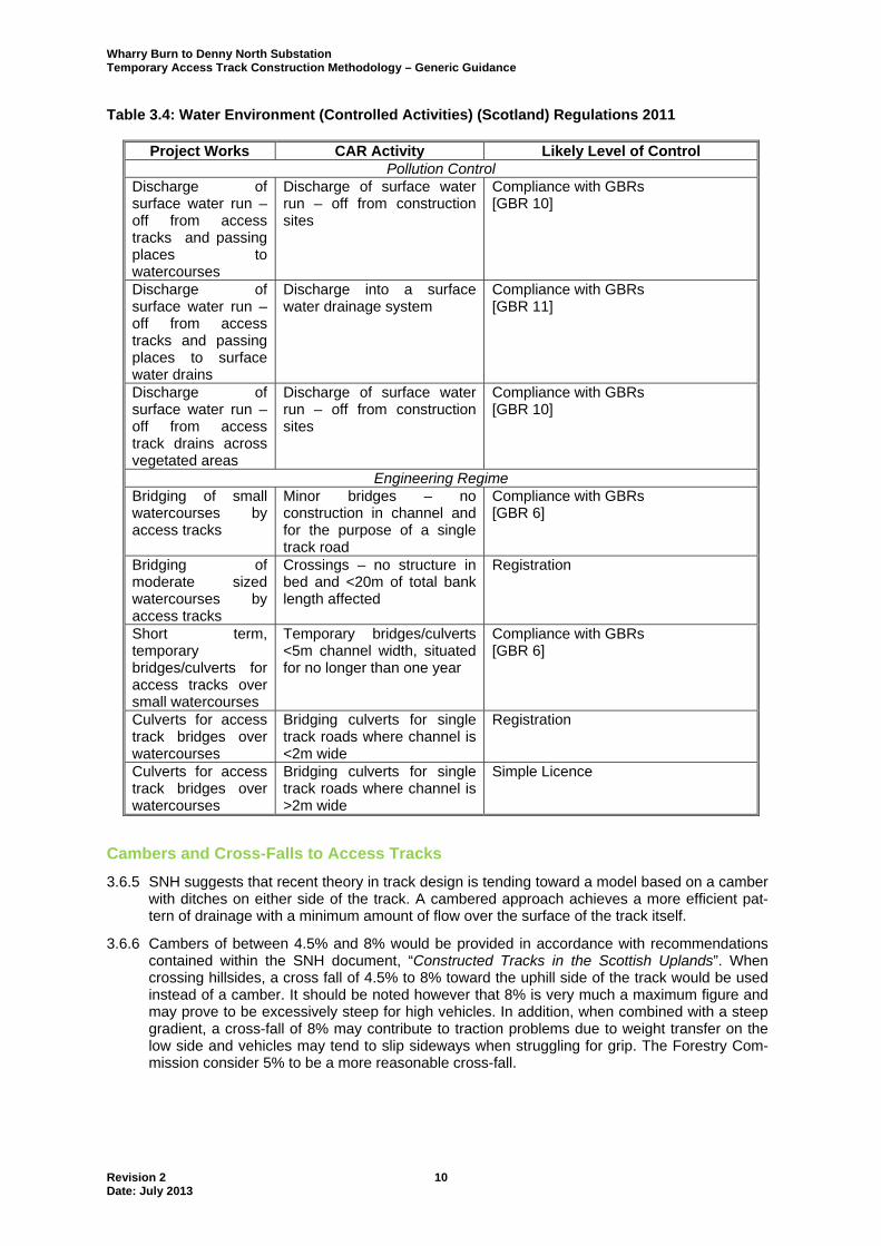
Table 3.4: Water Environment (Controlled Activities) (Scotland) Regulations 2011
Project Works CAR Activity Likely Level of Control
Pollution Control Discharge of surface water run – off from access tracks and passing places to watercourses
Discharge of surface water run – off from construction sites
Compliance with GBRs [GBR 10]
Discharge of surface water run – off from access tracks and passing places to surface water drains
Discharge into a surface water drainage system
Compliance with GBRs [GBR 11]
Discharge of surface water run – off from access track drains across vegetated areas
Discharge of surface water run – off from construction sites
Compliance with GBRs [GBR 10]
Engineering Regime Bridging of small watercourses by access tracks
Minor bridges – no construction in channel and for the purpose of a single track road
Compliance with GBRs [GBR 6]
Bridging of moderate sized watercourses by access tracks
Crossings – no structure in bed and <20m of total bank length affected
Registration
Short term, temporary bridges/culverts for access tracks over small watercourses
Temporary bridges/culverts <5m channel width, situated for no longer than one year
Compliance with GBRs [GBR 6]
Culverts for access track bridges over watercourses
Bridging culverts for single track roads where channel is <2m wide
Registration
Culverts for access track bridges over watercourses
Bridging culverts for single track roads where channel is >2m wide
Simple Licence
Cambers and Cross-Falls to Access Tracks
3.6.5 SNH suggests that recent theory in track design is tending toward a model based on a camber with ditches on either side of the track. A cambered approach achieves a more efficient pat-tern of drainage with a minimum amount of flow over the surface of the track itself.
3.6.6 Cambers of between 4.5% and 8% would be provided in accordance with recommendations contained within the SNH document, “Constructed Tracks in the Scottish Uplands”. When crossing hillsides, a cross fall of 4.5% to 8% toward the uphill side of the track would be used instead of a camber. It should be noted however that 8% is very much a maximum figure and may prove to be excessively steep for high vehicles. In addition, when combined with a steep gradient, a cross-fall of 8% may contribute to traction problems due to weight transfer on the low side and vehicles may tend to slip sideways when struggling for grip. The Forestry Com-mission consider 5% to be a more reasonable cross-fall.

Wharry Burn to Denny North Substation Temporary Access Track Construction Methodology – Generic Guidance
Revision 2 11 Date: July 2013
Water Breaks
3.6.7 SNH recommends that water breaks (comprising timber or metal sections laid across the track and orientated downslope) are required where gradients are likely to result in water flowing down the surface of the track, rather than directly to the sides. Water breaks interrupt such flows and divert flows into the drainage ditches constructed on either side of the track.
3.6.8 Water breaks may be constructed from railway sleepers or timber battens, buried into the sur-face of the track. They would however require regular maintenance as they can quickly be-come blinded with silt and can be easily damaged by passing vehicles. They can also impede road maintenance by grader. Water breaks would only be used as a last resort if suitable track gradients cannot be achieved by careful design.
Ditches
3.6.9 Ditches would be installed to intercept water and drain the track formation and construction. Their other function is to keep all water in its original catchment. Tracks using a camber (whether floated or overlay type) would have a ditch excavated on either side to collect run-off. Tracks on hillsides, constructed with a cross fall of 4.5% to 8% to the uphill side of the track would have a ditch located on the uphill side only. Ditches would typically be a minimum of 500mmm deep and have a minimum width of 700mm across the top edges. The sides of drainage ditches would be battered back to stable slopes (this is particularly important in peat to avoid collapse of the ditch). A minimum gradient of 2.5% (1 in 40) would be adopted for drainage ditches. It should be noted that gradients should not be sufficiently steep as to create erosion problems.
3.6.10 Ditches would not discharge directly to watercourses. Ditch runs would be broken up with a ‘herring bone’ pattern of horizontal ditches to act as silt traps. The herring bone ditches would be angled slightly uphill and directed toward buffer zones on forestry or moorland slopes. Hay bales would be inserted in the roadside ditches just downstream of the junction with each of the herring bone ditches to provide attenuation of flows.
3.6.11 If possible, main drainage ditches on the high side of tracks would extend beyond bends in the track and discharge onto buffer zones on forested or moorland slopes wherever possible to reduce the volume of run-off in the ditch. Roadside ditches would also terminate in buffer zones (or settling lagoons if sufficient land area is available).
3.6.12 The width of buffer zones varies depending on the channel width of the receiving watercourse. The Forestry Commission Document, “Forest & Water Guidelines – 4th Edition”, recommends the following: a buffer zone width of 20m on either side of watercourses with a channel more than 2m
wide; a minimum buffer zone width of 20m along the shores of lakes and reservoirs; a minimum buffer zone width of 10m on either side of watercourses with channels 1m-2m
wide; a minimum buffer zone width of 5m on either side of watercourses with channels up to 1m
wide (unless highlighted as being important for fish spawning, when a minimum buffer width of 10m would apply to either side of the watercourse).
3.6.13 Where the natural riparian zone exceeds these widths, the dimensions of the buffer area would be correspondingly increased, up to twice the minimum recommended width.
3.6.14 Where installed, settling lagoons would be designed to provide sufficient attenuation and set-tlement to remove the finest suspended particles from surface runoff at flows up to and includ-ing the 1 in 50 year return period event. Settling lagoons would discharge to grassland or for-estry buffer zones.
3.6.15 On sloping ground, cut-off ditches would be excavated above the access track to reduce the volume of surface water run-off reaching the track. Ditches on the upper side of tracks would be culverted to the lower side a short distance before stream crossings so as to prevent direct discharge to water courses.

Wharry Burn to Denny North Substation Temporary Access Track Construction Methodology – Generic Guidance
Revision 2 12 Date: July 2013
Culverts and Bridges
3.6.16 Watercourses would be crossed with either culverts or bridges. Construction traffic would not be permitted to ford watercourses. Watercourses and ditches sufficiently small that they are not shown on the 1:10,000 series Ordnance Survey maps would be crossed with simple pipe and stone culverts.
3.6.17 Watercourses shown on the 1:10,000 series Ordnance Survey maps and up to 5m wide would be crossed with corrugated steel ‘Armco’ style arch or pipe arch culverts, depending on SEPA requirements.
3.6.18 Any watercourse crossing of width 5m or greater would generally be bridged, unless methods more appropriate to the specific watercourse were identified. Arch culverts and bridges should have sufficient span that no works are required in channel inverts and the banks are kept free for mammal movements. Tracks would also be re-routed to avoid identified protected mammal habitats e.g. otter holts and resting up areas or water vole breeding grounds.
3.6.19 Photographs of bridge and pipe arch culvert installations similar to those proposed are shown in Plate Nos 3, 4 and 5 below.
Plate 3: Typical Steel Beam and Concrete Deck Bridge for Spans 10m to 20m

Wharry Burn to Denny North Substation Temporary Access Track Construction Methodology – Generic Guidance
Revision 2 13 Date: July 2013
Plate 4: Typical Small Span Bridge Crossing
Plate 5: Corrugated Steel Pipe Arch Culvert
3.6.20 All structures would be designed to accommodate a flood return period that would be agreed with SEPA, plus an uplift to account for climate change. Arch and pipe arch culverts would be designed in accordance with the requirements of CIRIA Report 168. Bridges would be de-signed in accordance with the Design Manual for Roads & Bridges (DMRB). Both would be designed to take loadings from the heaviest item of construction plant (100 tonne crane).

Wharry Burn to Denny North Substation Temporary Access Track Construction Methodology – Generic Guidance
Revision 2 14 Date: July 2013
3.6.21 Pipe arch culverts can obstruct the passage of fish, e.g. salmon and brown trout. These cul-verts would be designed to permit the passage of fish and other species by providing a culvert floor that has the same gradient and level and carries similar bed material as the original wa-tercourse.
3.6.22 HPPE pipe cross-drain culverts would also run under the tracks at regular intervals between watercourse crossings to keep runoff in its own catchment and avoid water travelling long dis-tances along the roadside ditches (with associated potential for causing scour damage). Cross - drains would be at least 600mm internal diameter and have a minimum internal gradient of 1% (1 in 100).
3.6.23 Stone aprons or large single stones would be constructed on the downstream side of cross- drains to provide energy dissipation of the flows and prevent problems of erosion. Stone lined catch pits would be constructed on the upstream side of the cross-drain to retain silt. External faces of cross-drains would be stone faced and the culvert pipes recessed to a depth of 150mm within the stonework to provide a feature that is sensitive to the surrounding land-scape.
Silt Traps and Soakaways
3.6.24 Increased silt levels in watercourses can result in significant natural heritage impacts. Where run-off from the track itself is likely to have a high silt content, silt traps would be constructed at regular intervals. Traps would be located at points where the water enters a cross-drain cul-vert or joins a natural watercourse and comprise a pit excavated below the level of the incom-ing ditch and outgoing culvert. Water entering the silt trap would slow, allowing material held in suspension to settle out.
3.6.25 Silt traps would be of adequate length to allow settlement (nominally 750mm to 1000mm long depending on the velocity of incoming flow). Silt traps and culverts would be stone faced to help the feature blend into the surrounding landscape and minimise longer-term maintenance requirements. Where flows are likely to be low, surface water run-off can be directed to soak-aways. These drains stop before they reach a watercourse, with the result that water soaks through the ground, removing suspended sediment.

ANNEX A ACCESS TRACKS CONSTRAINTS CHECKLIST


Access Tracks Constraints Checklist
Question? Response if Yes Information Source
Is there a risk of the track remaining permanent Design track to reduce environmental impacts
Planning permission required No permanent tracks in statutory
designated areas, IHAs, IMAs and IBAs
Is there an existing track that can be used Use if possible with spurs where required -
Is there a European Designated Site within the LOD
Avoid if possible. Where unavoidable, use Special Study report – Alignments are already fixed and all are
temporary tracks
Appendix D, 1.4.2.2 ES Technical Annex 22.1 (Special
Study Areas) –(
Could there be an indirect effect on a European Designated Site
Avoid if possible. Check Special Study reports and note for example if working upstream of a EDS, close to wintering bird SPA and detail mitigation to avoid risk
of impact
ES Appendix C Mitigation and CPH Section TBC –
(
Is there a National or Locally Designated Site within the LOD
Avoid if possible, where unavoidable detail mitigation to avoid / reduce risk of impact
ES Appendix C Mitigation and CPH Section TBC –
(
Has any habitat been mapped as sensitive, is there an IHA, or any sensitive plant species mapped
Avoid if possible, where unavoidable go through lowest value habitat where possible and seek
specialist advice
Access Track Environmental Constraints Report - ( Seek
advice if unsure
Are there any protected species or IMAs within the LOD
Avoid if possible, some constraints are legal obligations and committed mitigation, others may
relate to areas of protected species habitat. Where unavoidable seek specialist advice
ES Appendix C Mitigation ( Seek advice if unsure
Are there any Fresh Water Pearl Mussel Watercourses
Avoid where possible, where unavoidable seek specialist advice
ES Appendix C Mitigation ( Seek advice if unsure
Are there any sensitive breeding birds mapped or an IBA
Avoid if possible. Constraints may be seasonal. Identify nature of constraint from GIS data and follow
guidance in CPH. Where unavoidable seek specialist advice
Breeding bird guidance in Section TBC of the CPH and Annex E of
the ES
Are there any known Archaeological Sites within the
LOD or in the proximity
Avoid if possible. If unavoidable refer to mitigation detailed in the ES
Archaeological mitigation for each site within Section TBC of the ES
( Seek advice if unsure
Is there any commercial forestry within the LOD
Locate track within the 80m corridor for the line Where other environmental constraints present avoid if possible (as above), where unavoidable tracks outside
80m may require detailed mitigation
ES Appendix E and Section TBC of the CPH
( Seek advice if unsure
Is there any arable land within the LOD
Locate track around field periphery in liaison with land owners.
Where other environmental constraints are present avoid, if unavoidable refer to specific mitigation
Appendix D, 1.3.1.2 ( Seek advice if unsure
Are there any nearby residential properties
Avoid by at least 100m (subject to other environmental constraints) unless natural topography and existing
tracks etc provide mitigation
Ensure noise commitments and other mitigation in the ES are met
Is the route in proximity to or does it cross a watercourse
Avoid multiple crossings Check constraints maps for other sensitivities, e.g.
sensitive watercourses with regard to species and/or designations. N.B. These may be downstream (e.g.
IMAs etc)
Mitigation in Appendix E of the ES Special Study Reports and Section
TBC in CPH
Is access by Helicopter Required Consider potential environmental effects, including restrictions in relation to breeding birds, and detail
mitigation
Appendix E of the ES and Section of the CPH
ENSURE ALL PROPOSED ROUTES SIGNED OFF BY ENVIRONMENTAL REPRESENTATIVE/ECOLOGICAL SPECIALIST
( Where these cannot be avoided seek specialist advice Seek specialist advice where there is potential conflict between constraints
