bedienungsanleitung owner’s handbook · motorcycle. at the time of printing, the handbook covered...
TRANSCRIPT

OWNER’S HANDBOOK
ART. NR. 3.205.42
3.98
BEDIENUNGSANLEITUNG
640

EN
GLIS
H
1
Please insert the series numbers of your motorcycle in the boxes below
Frame number
Engine number
Stamp of dealer
IMPORTANTWE STRONGLY SUGGEST THAT YOU READ THIS HAND-BOOK CAREFULLY AND COMPLETELY BEFORE YOUTAKE YOUR FIRST RIDE. IT CONTAINS INFORMATIONAND TIPS THAT WILL BE ABLE YOU TO OPERATE ANDHANDLE YOUR MOTORCYCLE PROPERLY.PAY ATTENTION ESPECIALLY TO THE FOLLOWINGINSTRUCTIONS:
� WARNING �IGNORING THESE INSTRUCTIONS CAN ENDANGER YOUR BODYAND YOUR LIFE.
! CAUTION !IGNORING THESE INSTRUCTIONS COULD CAUSE DAMAGE TOPARTS OF YOUR MOTOR-BIKE OR THAT THE MOTOR-CYCLE ISNOT ROAD-SAFE ANYMORE.
TAMPERING WITH NOISE CONTROL SYSTEM PROHIBITEDOwners are warned that the law may prohibit:(a) The removal or rendering inoperative by any person other than for purposes of mainten-
ance, repair or replacement, of any device or element of design incorporated into anynew vehicle for the purpose of noise control prior to its sale or delivery to the ultimatepurchaser or while it is in use; and
(b) the use of the vehicle after such device or element of design has been removed or ren-dered inoperative by any person.
COMSUMER INFORMATION FOR AUSTRALIA ONLY

EN
GLIS
H
2
Introduction
We would like to congratulate you on your purchase of a KTM motorcycle.
You are now owner of a sporty and modern motorcycle which you are bound tohave a great time with, provided you care for it properly. This manual will furnishyou with important information on how to operate and maintain your new KTMmotorcycle. At the time of printing, the handbook covered the most up-to-datemodels in this series. It is, however, possible that we may have made slight modi-fications in the meantime due to development in our motorcycle design.
Many motorcyclists have a good working knowledge of motorcycle mechanics; ifthis is true in your case, you will be able to use this manual to carry out most ofthe maintenance steps yourself. If, on the other hand, you are not very familiarwith motorcycles, it might be better to have a professional KTM dealer performthose steps marked * described in the chapter entitled “Maintenance Work onChassis and Engine” of this manual.
Take special care to follow the recommended run in, inspection, and maintenanceintervals. Heeding these guidelines will significantly increase the life of yourmotorcycle. Have services carried out by a KTM dealer so that your warrantyclaim remains intact.
We wish you a lot of fun when driving !
KTM Austria’s certificate of achievement for its Quality System ISO 9001 is thebeginning of an on-going total re-engineering quality plan for a brighter tomorrow.
KTM SPORTMOTORCYCLE AG5230 MATTIGHOFEN, AUSTRIA
ALL RIGHTS RESERVED TO MAKE ALTERATIONS TO DESIGN AND MODEL.

EN
GLIS
H
3
Page
SERIAL NUMBER LOCATIONS .............................................4
Chassis number ................................................................4
Engine number, engine type.............................................4
OPERATION INSTRUMENTS ...............................................4
Clutch lever ......................................................................4
Hand decompression lever................................................4
Choke lever ......................................................................5
Hand brake lever ..............................................................5
Indicator lamps.................................................................5
Ignition lock, steering lock ................................................5
Tachometer ......................................................................6
Tripmaster ........................................................................6
Changing the tripmaster TOTAL kilometer reading...........7
Tripmaster parametrization...............................................7
Combination switch..........................................................8
Starter tip switch, emergency OFF switch .........................8
Filler cap...........................................................................8
Fuel ..................................................................................8
Fuel taps...........................................................................9
Emergency fuel tap...........................................................9
Hot start device ................................................................9
Shift lever .......................................................................10
Kickstarter ......................................................................10
Foot brake pedal ............................................................10
Compression damping of fork ........................................10
Rebound damping of fork ..............................................10
Compression damping of shock absorber .......................11
Rebound damping of shock absorber .............................11
Helmet lock ....................................................................11
Baggage carrier ..............................................................11
DRIVING INSTRUCTIONS ..................................................12
PERIODIC MAINTENANCE-SCHEDULE ..............................16
MAINTENANCE WORK ON CHASSIS AND ENGINE ..........17
Tool set ..........................................................................17
Removing the seat..........................................................17
Bleeder screws front fork ................................................18
Checking and adjusting steering head bearing................18
Changing the spring preload of the shock absorber ........18
Lubricate shock absorber linkage ....................................19
Checking chain tension...................................................19
Correct chain tension......................................................19
Chain maintenance.........................................................20
Chain wear.....................................................................20
General information on KTM disc brakes ........................20
Page
Checking of free travel at the hand brake lever ..............21
Checking of brake fluid level - front brake......................21
Refilling the front brake fluid reservoir............................21
Checking the front brake pads........................................21
Changing the basic position of the foot brake pedal .......22
Check the rear brake fluid level ......................................22
Refilling the rear brake fluid reservoir .............................22
Checking the rear brake pads .........................................22
Dismounting and mounting the front wheel ...................23
Dismounting and mounting the rear wheel.....................23
Checking the shock absorbtion rubbers in the rear hub.......24
Tires, air pressure............................................................24
Checking spoke tension..................................................24
Battery ...........................................................................25
Charging the battery ......................................................25
Main fuse .......................................................................26
Fuse fan .........................................................................26
Removing and mounting the headlight mask..................26
Replacing the headlight bulb ..........................................26
Replacing the tachometer lamps.....................................27
Replacing the indicator lamps .........................................27
Cooling system...............................................................27
Checking the cooling liquid level ....................................28
Adjusting idling speed ....................................................28
Adjusting the throttle cable ............................................28
Adjusting the choke cable...............................................28
Adjusting the clutch cable...............................................28
Checking the adjustment of the hand decompression cable......29
Engine oil .......................................................................29
Checking the engine oil level ..........................................29
Oil circuit........................................................................29
Oil change and bleeding of the oil system ......................30
Changing the fine screen filter........................................30
Changing oil filter ..........................................................31
TROUBLE SHOOTING........................................................32
CLEANING..........................................................................35
CONSERVATION FOR WINTER OPERATION ....................35
STORAGE ...........................................................................35
Re-initation after time of storage....................................35
TECHNICAL SPECIFICATIONS - ENGINE ..........................36
TECHNICAL SPECIFICATIONS - CHASSIS...........................38
WIRING DIAGRAM.............................................APPENDIX 2
Index

EN
GLIS
H
4
Chassis numberThe chassis number is stamped on the right side of the steering head tube.Write this number into the relevant area on page 1.
Engine number, engine typeThe engine number and engine type are stamped on the right hand side ofthe engine below the chain sprocket. Write this number into the relevant areaon page 1.
Clutch leverThe clutch lever 1 is fitted on the left hand side of the handle bar. Whenengine is cold, there should allways be a play of 1–3 mm (0,04–0,1 in) atthis lever (measured at outer edge).
! CAUTION !IF THERE IS NO PLAY ON THE CLUTCH LEVER, THE CLUTCH WILL START TO SLIP. THECLUTCH WILL THEN OVERHEAT, DESTROYING THE CLUTCH LININGS.
Hand decompression leverThe hand decompression lever 2 is only used in two special cases:a)When the engine stalled.
It is possible that the starter motor is not able to crank the engine on thenext attempt. This is due to the fact that the automatic decompressordoesn’t work properly. If this happens, pull the manual decompressionlever and start again. Afterwards normal starting will be possible.
b) When you want to push the motorcycle.While pushing, pull the hand decompression lever to make it easier to getthe engine going.
! CAUTION !THE SETTING OF THE HAND DECOMPRESSION CABLE SHOULD BE REGULARLY CHECKED(SEE MAINTENANCE WORK). A LACK OF PLAY IN THE HAND DECOMPRESSION LEVER CANRESULT IN ENGINE DAMAGE.
SERIAL NUMBER LOCATIONS
OPERATION INSTRUMENTS
1-3 mm
1
2
EN
GLIS
H
5
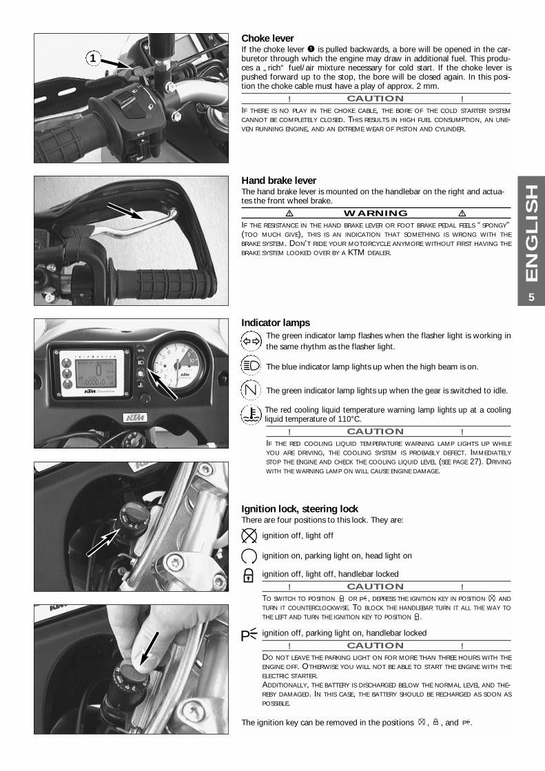
Choke leverIf the choke lever 1 is pulled backwards, a bore will be opened in the car-buretor through which the engine may draw in additional fuel. This produ-ces a „rich“ fuel/air mixture necessary for cold start. If the choke lever ispushed forward up to the stop, the bore will be closed again. In this posi-tion the choke cable must have a play of approx. 2 mm.
! CAUTION !IF THERE IS NO PLAY IN THE CHOKE CABLE, THE BORE OF THE COLD STARTER SYSTEMCANNOT BE COMPLETELY CLOSED. THIS RESULTS IN HIGH FUEL CONSUMPTION, AN UNE-VEN RUNNING ENGINE, AND AN EXTREME WEAR OF PISTON AND CYLINDER.
Hand brake leverThe hand brake lever is mounted on the handlebar on the right and actua-tes the front wheel brake.
� WARNING �IF THE RESISTANCE IN THE HAND BRAKE LEVER OR FOOT BRAKE PEDAL FEELS “SPONGY”(TOO MUCH GIVE), THIS IS AN INDICATION THAT SOMETHING IS WRONG WITH THEBRAKE SYSTEM. DON’T RIDE YOUR MOTORCYCLE ANYMORE WITHOUT FIRST HAVING THEBRAKE SYSTEM LOOKED OVER BY A KTM DEALER.
Indicator lampsThe green indicator lamp flashes when the flasher light is working inthe same rhythm as the flasher light.
The blue indicator lamp lights up when the high beam is on.
The green indicator lamp lights up when the gear is switched to idle.
The red cooling liquid temperature warning lamp lights up at a coolingliquid temperature of 110°C.
! CAUTION !IF THE RED COOLING LIQUID TEMPERATURE WARNING LAMP LIGHTS UP WHILEYOU ARE DRIVING, THE COOLING SYSTEM IS PROBABLY DEFECT. IMMEDIATELYSTOP THE ENGINE AND CHECK THE COOLING LIQUID LEVEL (SEE PAGE 27). DRIVINGWITH THE WARNING LAMP ON WILL CAUSE ENGINE DAMAGE.
Ignition lock, steering lockThere are four positions to this lock. They are:
ignition off, light off
ignition on, parking light on, head light on
ignition off, light off, handlebar locked
! CAUTION !TO SWITCH TO POSITION OR , DEPRESS THE IGNITION KEY IN POSITION ANDTURN IT COUNTERCLOCKWISE. TO BLOCK THE HANDLEBAR TURN IT ALL THE WAY TOTHE LEFT AND TURN THE IGNITION KEY TO POSITION .
ignition off, parking light on, handlebar locked
! CAUTION !DO NOT LEAVE THE PARKING LIGHT ON FOR MORE THAN THREE HOURS WITH THEENGINE OFF. OTHERWISE YOU WILL NOT BE ABLE TO START THE ENGINE WITH THEELECTRIC STARTER. ADDITIONALLY, THE BATTERY IS DISCHARGED BELOW THE NORMAL LEVEL AND THE-REBY DAMAGED. IN THIS CASE, THE BATTERY SHOULD BE RECHARGED AS SOON ASPOSSIBLE.
The ignition key can be removed in the positions , , and .
P
P
P
1

EN
GLIS
H
6
TachometerThe tachometer 1 shows the engine speed in revolutions per minute (rpm).Do not push the engine into the red zone, which begins at 8500 rpm.
! CAUTION !– MAXIMUM RECOMMENDED ROTATION RATE IS 8500 RPM. ROTATION RATES EXCEE-
DING 8500 RPM WILL SHORTEN YOUR ENGINE’S LIFE. REFER ALSO TO THE SECTIONON RUNNING IN YOUR MOTORCYCLE TO BE FOUND IN THE “DRIVING INSTRUCTIONS”CHAPTER.
– THE TACHOMETER IS NOT SUPPOSED TO GET IN CONTACT WITH FUEL. WHIPE OFFSPLASHED FUEL ON THE PLASTIC PARTS IMMEDIATELY, OTHERWISE THE PLASTIC PARTSMIGHT GET DAMAGED VERY SOON.
TripmasterThe tripmaster 2 is a complete electronic device with a clock and differentmileage counters that are helpful during roadbook tours.The display is switched on and off together with the ignition.The contrast of the display can be adjusted with the contrast potentiometer 3.Turn it clockwise to increase and counterclockwise to reduce the contrast.
Display BASIC FUNCTIONA indicates the total number of kilometers that you have covered so far
with your motorcycle.B indicates the speed.C is the day mileage counter.
Press the � key to reset the day mileage counter to 0.D indicates the time.
NOTE:If you have pressed the E/R key by mistake, i.e. if you have switched tothe parametrization function but do not wish to change the basic settings,simply press the E/R button until DATA SAVING appears in the display.
Display ROADBOOKD indicates the time.E indicates the total distance* (e.g. the total distance covered in one day).
The total distance display is useful for roadbook tours. It is recommendedto reset the display to 0 at the beginning of every stage. Thus you cansimply compare the distance covered with the values of the roadbook.If the displayed value is found to deviate from the roadbook value at achecking point, it is possible to correct the value (see chapter Tripmasterdisplay value, Changing the total distance value).
F indicates the stretch*.The stretch display is also very useful for roadbook tours. The stretchvalue can, for example, be reset to 0 after refuelling, thus allowing easyestimation of the fuel reserve.To reset the stretch value to 0 depress the � button for more than 2seconds.
To return to the basic function display press the � button.
Instructions for the changing of the basic settings can be found in the chapterTripmaster parametrization.
* Display values B and E can be exchanged, depending on the basic setting.
D
D F
E
1
2 3
A B
C

EN
GLIS
H
7
Changing the Tripmaster TOTAL kilometer readingIf the TOTAL kilometer reading differs from the kilometers indicated in therally map (e.g. if you have taken the wrong road), the TOTAL value can becorrected.– Press the � key to switch to the ROADBOOK display.– Depress the E/R key for two seconds.
The 1st digit of the TOTAL reading flashes and can be altered with � and �.
– Press the E/R key.The 2nd digit flashes and can be altered with � and �.
– Press the E/R key.The 3rd digit flashes and can be altered with � and �.
– Press the E/R key.The 4th digit flashes and can be altered with � and �.
– Press the E/R key.The 5th digit flashes and can be altered with � and �.
– Press the E/R key.The 6th digit flashes and can be altered with � and �.
– Press the E/R key to finish the correction procedure.
Tripmaster parametrizationThe Tripmaster PARAMETRIZATION function can be used to change thebasic settings.– Press the � key to switch to the BASIC FUNCTION display.– Depress the E/R key for 2 seconds.
The HOURS of the time reading flash and can be altered with � and �.– Press the E/R key.
The MINUTES of the time reading flash and can be altered with � and �.– Press the E/R key.
CORRECT CIRCUMFERENCE, correct with � and � (+/- 10 %).Here the accuracy of the speedometer and of all kilometer counters canbe adjusted. The setting – 1% need not be changed when using thestandard tire (90/90-21 Metzeler Enduro 3). However, correcting the cir-cumference can be necessary when a different tire dimension is used onthe front wheel.Additionally, this function can be used to adjust the kilometer counter tothe rally map.
– Press the E/R key.SELECT LANGUAGE; use � and � to select either German or English.
– Press the E/R key.SELECT KILOMETER / MILES; use � and � to select either kilometers ormiles.
– Press the E/R key.SELECT 12 / 24 H; use � and � to select either the 12 or the 24 hourdisplay mode.
– Press the E/R key.ROADBOOK FUNCTION; use � and � to select either of the followingdisplay modes:TOTAL DISTANCE BIG / STRETCH SMALLSTRETCH BIG / TOTAL DISTANCE SMALL
– Press the E/R key.CORRECTION ROADBOOK 10/50/100 m.This function is not active in your model. A remote control device can beordered as an optional accessory.
– Press the E/R key.DATA SAVING - PLEASE WAIT; the basic settings are now stored in thememory. This memory does not rely on the battery so that the values arenot lost if the battery is disconnected.

EN
GLIS
H
8
Combination switchThe rocker switch LIGHTS 1 actuates the high beam or low beam.
High-beam light
Low-beam light
The switch 2 returns to central position after actuation. Press flasher switchtowards switch housing to switch off the flasher.
Flasher left
Flasher right
The horn is sounded with button 3. The light signal (high beam) is actuated with button 4.
Starter tip switch, emergency OFF switchUse the starter tip switch 5 to operate the electric starter.
! CAUTION !MAXIMUM PERIOD FOR CONTINUOUS STARTING: 5 SECONDS. WAIT AT LEAST 5SECONDS BEFORE TRYING AGAIN.
The emergency OFF switch 6 is mainly a safety and emergency switch andshould normally be ON.
If this symbol is visible on the switch, the engine can be started (i.e. the ignition circuit and the starter circuit are switched on).
If this symbol is visible on the switch, the engine can not be started(i.e. the ignition circuit and the starter circuit are interrupted).
Filler capTo open: Pull the tank venting hose 7 out if the steering head and turn thefiller cap anti-counterclockwise.To close: Screw on the filler cap clockwise. Place the tank venting hose inthe steering head, avoiding any kinks.
FuelThe LC4 engine needs premium gasoline with an octane number of 95 orhigher.
! CAUTION !USE UNLEADED PREMIUM GRADE GASOLINE (95 OCTANES). NEVER USE ANY GASOLINEHAVING LESS THAN 95 OCTANES BECAUSE IT MAY DAMAGE THE ENGINE.
1
4
1
2
3
5
6
7

EN
GLIS
H
9
� WARNING �GASOLINE IS HIGHLY FLAMMABLE AND POISONOUS. EXTREME CAUTION SHOULD BE USEDWHEN HANDLING GASOLINE. DO NOT REFUEL THE MOTORCYCLE NEAR OPEN FLAMES ORBURNING CIGARETTES. ALWAYS SWITCH OFF THE ENGINE BEFORE REFUELLING. BECAREFUL NOT TO SPILL GASOLINE ON THE ENGINE OR EXHAUST PIPE WHILE THE ENGINE ISHOT. WIPE UP SPILLS PROMPTLY. IF GASOLINE IS SWALLOWED OR SPLASHED IN THE EYES,SEEK A DOCTOR’S ADVICE IMMEDIATELY.
Fuel expands when its temperature rises. Therefore do not fill the tank tothe top (see fig.).
Fuel tapsThe motorcycle is equipped with two fuel taps. A fuel pump is installed topump the fuel from the tank to the carburetor.The left fuel tap A can each be turned to three different positions:OFF In this position the fuel tap is closed. No fuel can flow to the carburetor.ON When using the motorcycle, the twist grip must be set to the ON
position. Now fuel can flow to fuel pump. In this position the tankempties down to the fuel reserve of approx. 3.8 liters (1 US gallone).
RES The reserve, approximately 3.8 liters (1 US gallone), cannot be tappeduntil the twist grip is turned to the RES position. Fill the tank as soonas possible and remember to turn the twist grip back to the ON posi-tion so that you will have backup fuel next time, too.
! CAUTION !THE FUEL TAP MUST ALWAYS BE CLOSED WHEN THE MOTORCYCLE IS PARKING. OTHER-WISE THE CARBURETOR CAN OVERFLOW AND FUEL COULD FLOW INTO THE ENGINE.
NOTE:The fuel tap must be open during operation. The fuel tap must be closed forparking.
Emergency fuel tapThe second fuel tap B is located on the right front side of the tank. It isalways closed during operation and should only be opened in the followingcase of emergency:a) The engine has died because you have switched to the fuel reserve too
late or because the entire fuel reserve has already been consumed.b) Defective fuel pump
INSTRUCTIONS:– If the fuel reserve has been consumed, the motorcycle must be refuelled
(min 4 liter, 1 US gallone)– Open the emergency fuel tap (turn the knob anticlockwise). Now the
fuel can flow directly to the carburetor and the engine can be restarted.As soon as the engine is running, the fuel pump soon automaticallybleeds itself and then works normally again.
– Keep in mind to close the emergency fuel tap (by turning the knobclockwise). Otherwise no fuel reserve will be available the next time.
Hot start deviceThe carburetor is equipped with a hot start device which makes it easier tostart the engine when hot. Press the hot-start button 1 until it engages.This will slightly lift the throttle slide. Once the engine is running, pull thehot-start button back into its original position.NOTE:Always pull the hot start device back into the initial position as soon as theengine is running. An activated hot start device will have a negative impacton the cold starting properties of the engine.
NO
OFF
RES
FUE
L
NO
OFF
RES
FUE
L
NO
OFF
RES
FUE
L
35 mm
OFF ON RES
A
B
1

EN
GLIS
H
10
Shift leverThe shift lever is mounted on the left side of the engine. The position of thegears is shown in the illustration. Neutral, or the idle speed, is located bet-ween first and second gear.
KickstarterThe kickstarter is mounted on the left side of the engine. Its upper part canbe swivelled.
� WARNING �ALWAYS WEAR BOOTS WHEN USING THE KICKSTARTER TO AVOID INJURY.
Foot brake pedalThe foot brake pedal is located in front of the right footrest. Its basic posi-tion can be adjusted to your seat position (see maintenance work).
� WARNING �IF THE RESISTANCE IN THE HAND BRAKE LEVER OR FOOT BRAKE PEDAL FEELS “SPONGY”(TOO MUCH GIVE), THIS IS AN INDICATION THAT SOMETHING IS WRONG WITH THEBRAKE SYSTEM. DON’T RIDE YOUR MOTORCYCLE ANYMORE WITHOUT FIRST HAVING THEBRAKE SYSTEM LOOKED OVER BY A KTM DEALER.
Compression damping of fork The compression damping mechanism is built into the left fork tube. It onlyregulates the degree of damping during compression.By using the knob 1 (COM), the degree of damping of the compressioncan be adjusted. Turn the knob clockwise to increase damping, turn it coun-terclockwise to reduce damping during compression.
BASIC SETTING– turn rotary knob clockwise as far as it will go– turn it back counter-clockwise by as many clicks as are specified for the
relevant type of fork– 09.18.S7.55.........14 clicks
Rebound damping of forkThe rebound damping mechanism is built into the right fork tube. It onlyregulates the degree of damping during rebounding.By using the knob 2 (REB), the degree of damping of the rebound can beadjusted. Turn the knob clockwise to increase damping, turn it counter-clockwise to reduce damping during rebounding.
BASIC SETTING– turn rotary knob clockwise as far as it will go– turn it back counter-clockwise by as many clicks as are specified for the
relevant type of fork– 09.18.S7.55........ 12 clicks
2,3,4,5
1
N
1
2

EN
GLIS
H
11
Compression damping of shock absorberWith the knob 1 the degree of damping of the compression can be adju-sted to 7 positions. Turn the knob counterclockwise to increase damping,turn it clockwise to reduce damping during compression.
BASIC SETTING– 01.18.R7.97.........position 3
Rebound damping of shock absorberWith the setting wheel 2 the degree of damping of the rebound can beadjusted to 11 positions. Turn the knob to the left side to increase damping,turn it to the right side to reduce damping during rebounding.
BASIC SETTING:– 01.18.R7.97.........position 5
� WARNING �– NEVER CHANGE DAMPING BETWEEN THE TEST DRIVES MORE THAN 2 CLICKS.– THE DAMPING UNIT OF THE SHOCK ABSORBER IS FILLED WITH HIGHLY COMPRESSED
NITROGEN. NEVER TRY TO TAKE THE SHOCK ABSORBER APART OR TO DO ANY MAIN-TENANCE WORK YOURSELF. SEVERE INJURIES COULD BE THE RESULT.
Helmet lockA helmet lock 3 is located on the left side of the frame. To unlock it, insertignition key and turn it clockwise. Hang helmet on rod, turn key counter-clockwise as far as it goes.
� WARNING �NEVER LEAVE YOUR HELMET ATTACHED TO HELMET LOCK WHEN RIDING YOURMOTORCYCLE BECAUSE THE HELMET CAN GET CAUGHT IN THE REAR WHEEL AND THROWTHE VEHICLE OUT OF CONTROL.
Baggage carrierThe baggage carrier may be loaded with up to 10 kg. The two lateral hoopsserve as handles for the passenger
1
2
3

EN
GLIS
H
12
– Do not drive along off-road tracks which go beyond yourability and experience.
– Hold the handlebar with both hands and leave your feet onthe foot rests while driving.
– Remove your foot from the foot brake pedal when you arenot braking. If the foot brake pedal is not released the brakepads rub continuously and the braking system is overhea-ted.
– You may only be accompanied by a passenger if yourmotorcycle is fitted and registered for such purposes. Thepassenger must hold tight to the brackets or hold on to thedriver during the drive, with his feet on the passenger footrests.
– Do not make any alterations to the motorcycle and alwaysuse ORIGINAL KTM SPARE PARTS. Spare parts from othermanufacturers can impair the safety of the motorcycle.
– Motorcycles are sensitive to alterations in the distribution ofweight. If you are taking luggage with you, this should besecured as close as possible to the middle of the vehicle; dis-tribute the weight evenly between the front and rear wheel.Never exceed the maximum permissible laden weight andthe axle weights. The maximum permissible laden weight ismade up of the following components:– Motorcycle ready for operation and tank full– Luggage– Driver and passenger with protective clothing and helmet.
– Pay attention to running in instructions.
Running in Even finely machined surfaces of engine parts have roughersurfaces than parts that slide on each other for a long time.Therefore, every engine must be run in. For this reason, do notdemand maximum performance from the engine for the first100 kilometers. The vehicle must be run in at low, changingperformance level for the first 1000 KM (620 miles). The maxi-mum number of revolutions per minute must not go exceed4800 rpm. Do not accelerate the engine up to the red mark onthe tachometer (8500 r.p.m.) during a running-in period of1000 km. Exceeding the above listed rotations as well as pus-hing high rpm when the engine is cold will have an adverseeffect on the life of your engine.
NOTE:DURING THE STAGE OF RUNNING THE ENGINE IN, THAT IS THE FIRST 1000KM (620 MILES), THE ENGINE OIL USED SHOULD BE OF A MINERAL OILFORMULA. THIS ALSO APPLIES IF THE ENGINE HAS BEEN REPAIRED.
Check the following before each startWhen you start off, the motorcycle must be in a perfect technicalcondition. For safety reasons, you should make a habit of perfor-ming an overall check of your motorcycle before each start.The following checks should be performed:1 CHECK THE OIL LEVEL
Insufficient oil results in premature wear and consequentlyto engine damage.
2 FUELCheck that there is sufficient fuel in the tank; when closing thefiller cap, check that the tank venting hose is free of kinks.
3 CHAINA loose chain can fall off; an extremely worn chain can tear,and insufficient lubrication can result in unnecessary wear tothe chain and rear sprockets.
4 TIRESCheck for damaged tires. Tires showing cuts or dents mustbe replaced. The tread depth must comply with the legalregulations. Also check the air pressure. Insufficient treadand incorrect air pressure reduce the driving performance.
5 BRAKESCheck correct functioning of the braking system. Check forsufficient brake fluid in the reservoir. The reservoirs havebeen designed in such a way that brake fluid does not needto be refilled even when the brake pads are worn. If thelevel of brake fluid falls below the minimum value, this indi-cates a leak in the braking system or completely worn outbrake pads. Arrange for the braking system to be checkedby a KTM specialist garage, as complete failure of the bra-king system can be expected.Also check the state of the brake hoses and the thickness ofthe brake linings.Check free travel at hand brake lever and foot brake pedal.
6 CABLESCheck correct setting and easy running of all control cables.
7 COOLING LIQUIDCheck the level of cooling liquid when the engine is cold.
8 ELECTRICAL SYSTEMCheck headlight, parking light, tail light, brake light, flas-hers, indicator lamps and horn for faultless operation.
9 LUGGAGEIf you are taking luggage with you, check that this is secu-rely fastened.
� WARNING �– WEAR SUITABLE CLOTHING WHEN DRIVING A MOTORCYCLE. CLEVER
KTM DRIVERS ALWAYS WEAR A HELMET, BOOTS, GLOVES AND AJACKET, REGARDLESS OF WHETHER DRIVING ALL DAY OR JUST FOR ASHORT TRIP. THE PROTECTIVE CLOTHING SHOULD BE BRIGHTLYCOLOURED SO THAT OTHER USERS OF THE ROADS CAN SEE YOU ASEARLY AS POSSIBLE. YOUR PASSENGER OF COURSE WILL ALSO NEEDSUITABLE PROTECTIVE CLOTHING.
– DO NOT DRIVE AFTER HAVING CONSUMED ALCOHOL.– ONLY USE ACCESSORIES THAT HAVE BEEN RELEASED BY KTM. FOR
EXAMPLE, FRONT PANELLING CAN IMPAIR THE DRIVING PROPERTIES OFTHE MOTORCYCLE. CASES, EXTRA TANKS ETC. CAN ALTER THE WEIGHTDISTRIBUTION AND THUS ALSO IMPAIR THE VEHICLE’S DRIVING PRO-PERTIES.
– THE FRONT AND REAR WHEEL ARE ONLY ALLOWED TO BE TIRED WITHTIRES THAT HAVE THE SAME PROFILE TYPE.
Instructions for initial operation– Verify that your KTM dealer performed the PREPARATION
OF VEHICLE jobs (see Customer Service Manual).– Read the entire manual carefully before your first drive.– Familiarize yourself with the operating elements.– Adjust the foot brake pedal to the most comfortable positi-
ons for you.– Get used to handling the motorcycle on an empty car park,
before starting on a longer drive. Also try to drive as slowlyas possible and in standing position, to improve your feelingfor the vehicle.
DRIVING INSTRUCTIONS
EN
GLIS
H
13
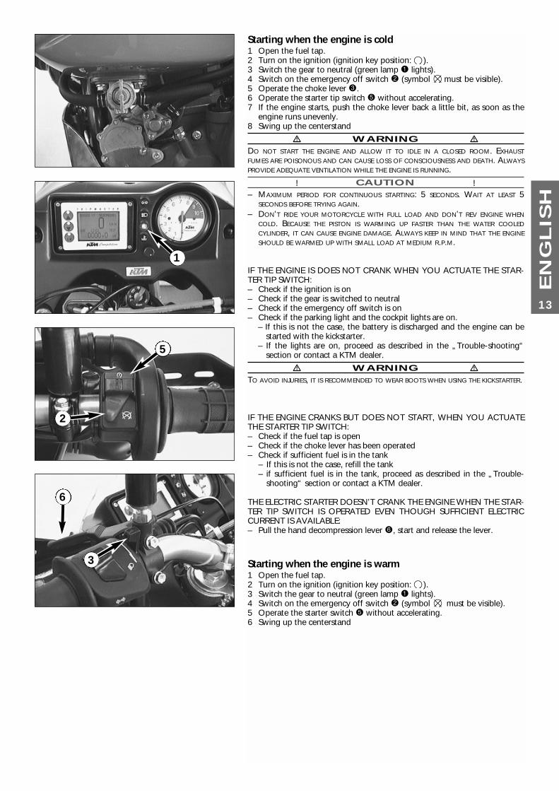
Starting when the engine is cold1 Open the fuel tap.2 Turn on the ignition (ignition key position: ).3 Switch the gear to neutral (green lamp 1 lights).4 Switch on the emergency off switch 2 (symbol must be visible).5 Operate the choke lever 3. 6 Operate the starter tip switch 5 without accelerating.7 If the engine starts, push the choke lever back a little bit, as soon as the
engine runs unevenly.8 Swing up the centerstand
� WARNING �DO NOT START THE ENGINE AND ALLOW IT TO IDLE IN A CLOSED ROOM. EXHAUSTFUMES ARE POISONOUS AND CAN CAUSE LOSS OF CONSCIOUSNESS AND DEATH. ALWAYSPROVIDE ADEQUATE VENTILATION WHILE THE ENGINE IS RUNNING.
! CAUTION !– MAXIMUM PERIOD FOR CONTINUOUS STARTING: 5 SECONDS. WAIT AT LEAST 5
SECONDS BEFORE TRYING AGAIN.– DON’T RIDE YOUR MOTORCYCLE WITH FULL LOAD AND DON’T REV ENGINE WHEN
COLD. BECAUSE THE PISTON IS WARMING UP FASTER THAN THE WATER COOLEDCYLINDER, IT CAN CAUSE ENGINE DAMAGE. ALWAYS KEEP IN MIND THAT THE ENGINESHOULD BE WARMED UP WITH SMALL LOAD AT MEDIUM R.P.M.
IF THE ENGINE IS DOES NOT CRANK WHEN YOU ACTUATE THE STAR-TER TIP SWITCH:– Check if the ignition is on– Check if the gear is switched to neutral– Check if the emergency off switch is on– Check if the parking light and the cockpit lights are on.
– If this is not the case, the battery is discharged and the engine can bestarted with the kickstarter.
– If the lights are on, proceed as described in the „Trouble-shooting“section or contact a KTM dealer.
� WARNING �TO AVOID INJURIES, IT IS RECOMMENDED TO WEAR BOOTS WHEN USING THE KICKSTARTER.
IF THE ENGINE CRANKS BUT DOES NOT START, WHEN YOU ACTUATETHE STARTER TIP SWITCH:– Check if the fuel tap is open– Check if the choke lever has been operated– Check if sufficient fuel is in the tank
– If this is not the case, refill the tank– if sufficient fuel is in the tank, proceed as described in the „Trouble-
shooting“ section or contact a KTM dealer.
THE ELECTRIC STARTER DOESN’T CRANK THE ENGINE WHEN THE STAR-TER TIP SWITCH IS OPERATED EVEN THOUGH SUFFICIENT ELECTRICCURRENT IS AVAILABLE:– Pull the hand decompression lever 6, start and release the lever.
Starting when the engine is warm1 Open the fuel tap.2 Turn on the ignition (ignition key position: ).3 Switch the gear to neutral (green lamp 1 lights).4 Switch on the emergency off switch 2 (symbol must be visible).5 Operate the starter switch 5 without accelerating.6 Swing up the centerstand
1
2
5
3
6
EN
GLIS
H
14
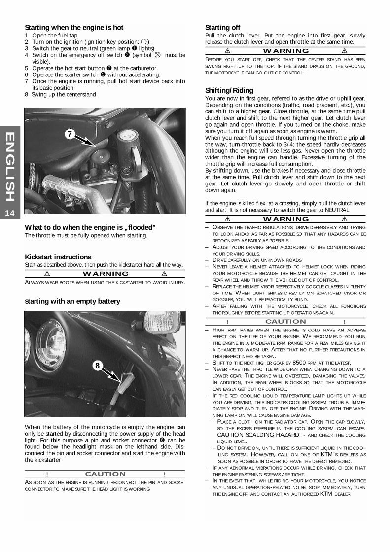
Starting when the engine is hot1 Open the fuel tap.2 Turn on the ignition (ignition key position: ).3 Switch the gear to neutral (green lamp 1 lights).4 Switch on the emergency off switch 2 (symbol must be
visible).5 Operate the hot start button 7 at the carburetor.6 Operate the starter switch 5 without accelerating.7 Once the engine is running, pull hot start device back into
its basic position8 Swing up the centerstand
What to do when the engine is „flooded”The throttle must be fully opened when starting.
Kickstart instructionsStart as described above, then push the kickstarter hard all the way.
� WARNING �ALWAYS WEAR BOOTS WHEN USING THE KICKSTARTER TO AVOID INJURY.
Starting with an empty battery
When the battery of the motorcycle is empty the engine canonly be started by disconnecting the power supply of the headlight. For this purpose a pin and socket connector 8 can befound below the headlight mask on the lefthand side. Dis-connect the pin and socket connector and start the engine withthe kickstarter
! CAUTION !AS SOON AS THE ENGINE IS RUNNING RECONNECT THE PIN AND SOCKETCONNECTOR TO MAKE SURE THE HEAD LIGHT IS WORKING
Starting offPull the clutch lever. Put the engine into first gear, slowlyrelease the clutch lever and open throttle at the same time.
� WARNING �BEFORE YOU START OFF, CHECK THAT THE CENTER STAND HAS BEENSWUNG RIGHT UP TO THE TOP. IF THE STAND DRAGS ON THE GROUND,THE MOTORCYCLE CAN GO OUT OF CONTROL.
Shifting/RidingYou are now in first gear, refered to as the drive or uphill gear.Depending on the conditions (traffic, road gradient, etc.), youcan shift to a higher gear. Close throttle, at the same time pullclutch lever and shift to the next higher gear. Let clutch levergo again and open throttle. If you turned on the choke, makesure you turn it off again as soon as engine is warm.When you reach full speed through turning the throttle grip allthe way, turn throttle back to 3/4; the speed hardly decreasesalthough the engine will use less gas. Never open the throttlewider than the engine can handle. Excessive turning of thethrottle grip will increase full consumption. By shifting down, use the brakes if necessary and close throttleat the same time. Pull clutch lever and shift down to the nextgear. Let clutch lever go slowely and open throttle or shiftdown again.
If the engine is killed f.ex. at a crossing, simply pull the clutch leverand start. It is not necessary to switch the gear to NEUTRAL.
� WARNING �– OBSERVE THE TRAFFIC REGULATIONS, DRIVE DEFENSIVELY AND TRYING
TO LOOK AHEAD AS FAR AS POSSIBLE SO THAT ANY HAZARDS CAN BERECOGNIZED AS EARLY AS POSSIBLE.
– ADJUST YOUR DRIVING SPEED ACCORDING TO THE CONDITIONS ANDYOUR DRIVING SKILLS.
– DRIVE CAREFULLY ON UNKNOWN ROADS– NEVER LEAVE A HELMET ATTACHED TO HELMET LOCK WHEN RIDING
YOUR MOTORCYCLE BECAUSE THE HELMET CAN GET CAUGHT IN THEREAR WHEEL AND THROW THE VEHICLE OUT OF CONTROL.
– REPLACE THE HELMET VISOR RESPECTIVELY GOGGLE GLASSES IN PLENTYOF TIME. WHEN LIGHT SHINES DIRECTLY ON SCRATCHED VISOR ORGOGGLES, YOU WILL BE PRACTICALLY BLIND.
– AFTER FALLING WITH THE MOTORCYCLE, CHECK ALL FUNCTIONSTHOROUGHLY BEFORE STARTING UP OPERATIONS AGAIN.
! CAUTION !– HIGH RPM RATES WHEN THE ENGINE IS COLD HAVE AN ADVERSE
EFFECT ON THE LIFE OF YOUR ENGINE. WE RECOMMEND YOU RUNTHE ENGINE IN A MODERATE RPM RANGE FOR A FEW MILES GIVING ITA CHANCE TO WARM UP. AFTER THAT NO FURTHER PRECAUTIONS INTHIS RESPECT NEED BE TAKEN.
– SHIFT TO THE NEXT HIGHER GEAR BY 8500 RPM AT THE LATEST.– NEVER HAVE THE THROTTLE WIDE OPEN WHEN CHANGING DOWN TO A
LOWER GEAR. THE ENGINE WILL OVERSPEED, DAMAGING THE VALVES.IN ADDITION, THE REAR WHEEL BLOCKS SO THAT THE MOTORCYCLECAN EASILY GET OUT OF CONTROL.
– IF THE RED COOLING LIQUID TEMPERATURE LAMP LIGHTS UP WHILEYOU ARE DRIVING, THIS INDICATES COOLING SYSTEM TROUBLE. IMME-DIATELY STOP AND TURN OFF THE ENGINE. DRIVING WITH THE WAR-NING LAMP ON WILL CAUSE ENGINE DAMAGE.– PLACE A CLOTH ON THE RADIATOR CAP. OPEN THE CAP SLOWLY,
SO THE EXCESS PRESSURE IN THE COOLING SYSTEM CAN ESCAPE.CAUTION SCALDING HAZARD! - AND CHECK THE COOLINGLIQUID LEVEL.
– DO NOT DRIVE ON, UNTIL THERE IS SUFFICIENT LIQUID IN THE COO-LING SYSTEM. HOWEVER, CALL ON ONE OF KTM’S DEALERS ASSOON AS POSSIBLE IN ORDER TO HAVE THE DEFECT REMEDIED.
– IF ANY ABNORMAL VIBRATIONS OCCUR WHILE DRIVING, CHECK THATTHE ENGINE FASTENING SCREWS ARE TIGHT.
– IN THE EVENT THAT, WHILE RIDING YOUR MOTORCYCLE, YOU NOTICEANY UNUSUAL OPERATION-RELATED NOISE, STOP IMMEDIATELY, TURNTHE ENGINE OFF, AND CONTACT AN AUTHORIZED KTM DEALER.
7
8

EN
GLIS
H
15
Stopping and parkingApply the brakes fully and put the engine into neutral. To stop the engine,switch off the ignition. Close fuel tap. Park on solid ground and lock thevehicle.
� WARNING �– NEVER LEAVE YOUR MOTORCYCLE WITHOUT SUPERVISION AS LONG AS THE ENGINE IS
RUNNING.– MOTORCYCLE ENGINES PRODUCE A GREAT AMOUNT OF HEAT WHILE RUNNING. THE
ENGINE RADIATORS, EXHAUST, EXHAUST SYSTEM, BRAKE DISCS, AND SHOCK ABSOR-BERS CAN BECOME VERY HOT. DO NOT TOUCH ANY OF THESE PARTS AFTER OPERA-TING THE MOTORCYCLE, AND TAKE CARE TO PARK IT WHERE PEDESTRIANS ARE NOTLIKELY TO TOUCH IT AND GET BURNED.
– NEVER PARK YOUR MOTORCYCLE IN PLACES WHERE THERE EXIST FIRE HAZARDS DUETO DRY GRASS OR OTHER EASILY FLAMMABLE MATERIALS.
! CAUTION !– PARK YOUR MOTORCYCLE, SO THAT IT RESTS STABLY ON THE SIDESTAND (HARD
GROUND, LEVEL SURFACE) AND CAN’T TIP OVER.– DO NOT LEAVE THE PARKING LIGHT ON FOR MORE THAN THREE HOURS WITH THE
ENGINE OFF. OTHERWISE YOU WILL NOT BE ABLE TO START THE ENGINE WITH THEELECTRIC STARTER.
– THE FUEL TAPS MUST ALWAYS BE CLOSED WHEN PARKING THE MOTORCYCLE.OTHERWISE THE CARBURETOR CAN OVERFLOW AND FUEL COULD FLOW INTO THEENGINE.
– ALWAYS TAKE OUT THE IGNITION KEY WHEN PARKING YOUR MOTORCYCLE SO THATIT CANNOT BE USED BY UNAUTHORIZED PERSONS.
NOTE REGARDING THE CENTER STAND:We advice the following procedure to place the motorcycle on the centerstand as effortlessly as possible:a) press main stand to ground using foot,b) swing out kickstarter and pull motocycle backwards at an angle as illustrated
(see illustration).Make sure that the ground is solid and that your motorcycle is standingsecurely.
! CAUTION !
BEFORE YOU START OFF, CHECK THAT THE CENTER STAND HAS BEEN SWUNG RIGHT UP TO THE
TOP. IF THE STAND DRAGS ON THE GROUND, THE MOTORCYCLE CAN GO OUT OF CONTROL.
BrakingClose throttle and apply the hand and foot brakes at the same time. Whendriving on sandy, wet or slippery ground use mainly the rear wheel brake.Always brake with feeling, blocking wheels can cause you to skid or fall.Also change down to lower gears depending on your speed.When driving downhill, use the braking effect of the engine. Change downone or two gears but do not overspeed the engine. In this way, you will notneed to brake so much and the brakes will not overheat.
� WARNING �WHEN YOU BRAKE, THE BRAKE DISCS, BRAKE PADS, BRAKE CALIPER AND BRAKE FLUIDHEAT UP. THE HOTTER THESE PARTS GET, THE WEAKER THE BRAKING EFFECT. IN EXTREMECASES, THE ENTIRE BRAKING SYSTEM CAN FAIL.

EN
GLIS
H
16
Check engine oil level �
Change engine oil � � �
Clean oil screen and magnet of the drain plugs whenever you exchange the engine oil �
Change oil filter insert � � �
Change fine screen filter (screwed filter) at front pipe (of the frame) � � �
Check oil lines for leakage and proper instalment without kinks � �
Check valve clearance � �
Clean spark plug and adjust electrode gap �
Change spark plug after 10 000 kilometers (6 200 miles)
Check ignition point �
Drain and clean carburetor float chamber � � �
Adjust idling �
Check breather hoses of engine gase and gas tank for correct position without buckles � �
Clean air filter and air filter box � � �
Check sprockets, chain guides and chain for wear � � �
Clean and lube chain � � �
Check chain tension � � �
Check cooling liquid level � � �
Check quality of antifreezer �
Check cooling system for leaks – visual check � � �
Check exhaust system for leakage �
Check exhaust brackets � �
Disassemble and clean spark arrestor discs (USA models)
Check brake fluid level front and rear � � �
Change brake fluid �
Check brake pad thickness � �
Check brake discs �
Check condition and correct instalment of brake hoses � � �
Check free play and easy operation of foot brake pedal � � �
Check adjustment and function of telescopic fork � �
Check telescopic fork for leaks �
Loosen bleeder screws at fork legs (overpressure) �
Change telescopic fork oil �
Perform a full maintenance job for the telescopic fork �
Clean dust scrabber of telescopic fork � �
Check steering head bearing clearance / adjust � �
Clean and grease steering head bearings and its seals �
Check adjustment and funktion of shock absorber � �
Check O-ring of the shock absorber for wear � �
Service the shock absorber �
Grease nipple of the Pro Lever suspension system �
Disassemble the Pro Lever suspension system linkage and perform a full maintenance job on it �
Service swingarm pivot �
Check spoke tension and join � � �
Check wheel bearings for clearance � �
Check shock absorber rubbers on the rear hub �
Check tire condition and air pressure � �
Check cables for damage and easy working � �
Lube and adjust cables � � �
Check the electrical system � � �
Check battery holder, battery and connections � �
Check adjustment of headlight �
Spray ignition lock, emergency off switch, and light switch with contact spray � �
Check all screws, nuts and hose clamps for proper tightness � � �
Grease or lube all pivot points and sliding points � � �
PERIODIC MAINTENANCE SCHEDULE
befo
re e
ach
star
t
afte
r w
ashi
ng
1st
serv
ice,
af
ter
500
km (
300
mile
s)
afte
r 25
00 k
m
(150
0 m
iles)
afte
r 50
00 k
m
(300
0 m
iles)
or
once
a y
ear
at le
ast
once
a y
ear
KTMrider
KTMdealer
IF THE MOTORCYCLE IS USED FOR COMPETITIVE RACING, THE 5000 KM(3000 MILES) SERVICE NEEDS TO BE CARRIED OUT AFTER EVERY RACE
EGS-E, Adventure 3.98

EN
GLIS
H
17
� WARNING �ALL MAINTENANCE AND ADJUSTEMENT OPERATIONS THAT ARE MARKED WITH A * REQUIRE SPECIALIST KNOW-LEDGE. FOR YOUR OWN SAFETY, LET THESE TASKS BE CARRIED OUT BY A KTM-DEALER
! CAUTION !– WHEN CLEANING THE MOTORCYCLE, DO NOT USE A HIGH PRESSURE CLEANING UNIT IF POSSIBLE, OTHERWISE WATER WILL PENETRATE THE BEARINGS, CAR-
BURETOR, ELECTRIC CONNECTORS ETC.– WHEN TRANSPORTING YOUR KTM, ENSURE THAT IT IS HELD UPRIGHT WITH RESTRAINING STRAPS OR OTHER MECHANICAL FASTENING DEVICES. IF THE
MOTORCYCLE SHOULD FALL OVER, FUEL CAN LEAK FROM THE CARBURETOR OR FUEL TANK– DO NOT USE TOOTHED WASHERS OR SPRING WASHERS WITH THE ENGINE FASTENING SCREWS, AS THESE WORK INTO THE FRAME PARTS AND KEEP WOR-
KING LOOSE. INSTEAD, USE SELF-LOCKING NUTS.– LET YOUR MOTORCYCLE COOL DOWN BEFORE BEGINNING ANY MAINTENANCE WORK IN ORDER TO AVOID GETTING BURNED.– DISPOSE OF OIL, GREASE, FILTERS, FUELS, CLEANING AGENTS ETC. ACCORDING TO YOUR LOCAL REGULATIONS.– UNDER NO CIRCUMSTANCES MAY USED OIL BE DISPOSED OF IN THE SEWAGE SYSTEM OR IN THE OPEN COUNTRYSIDE. 1 LITER USED OIL CONTAMINATES
1,000.000 LITERS WATER.
Tool setThe tool kit 1 is locted in the tool box under the right side cover.
Removing the seatRemove the collar screws 2 from the underside of the fender. Lift the rearof the seat, pull backwards, and unhook it from the oval-head screw 3.
To install the seat, hook the seat into the oval-head screw, set the rear portiondown on the frame, and slide it forward. If necessary, press down on thefront area of the seat so that the seat catches on the retaining bracket 4. Insert and tighten the collar screw.
MAINTENANCE WORK ON CHASSIS AND ENGINE
1
2
2
3
4
EN
GLIS
H
18
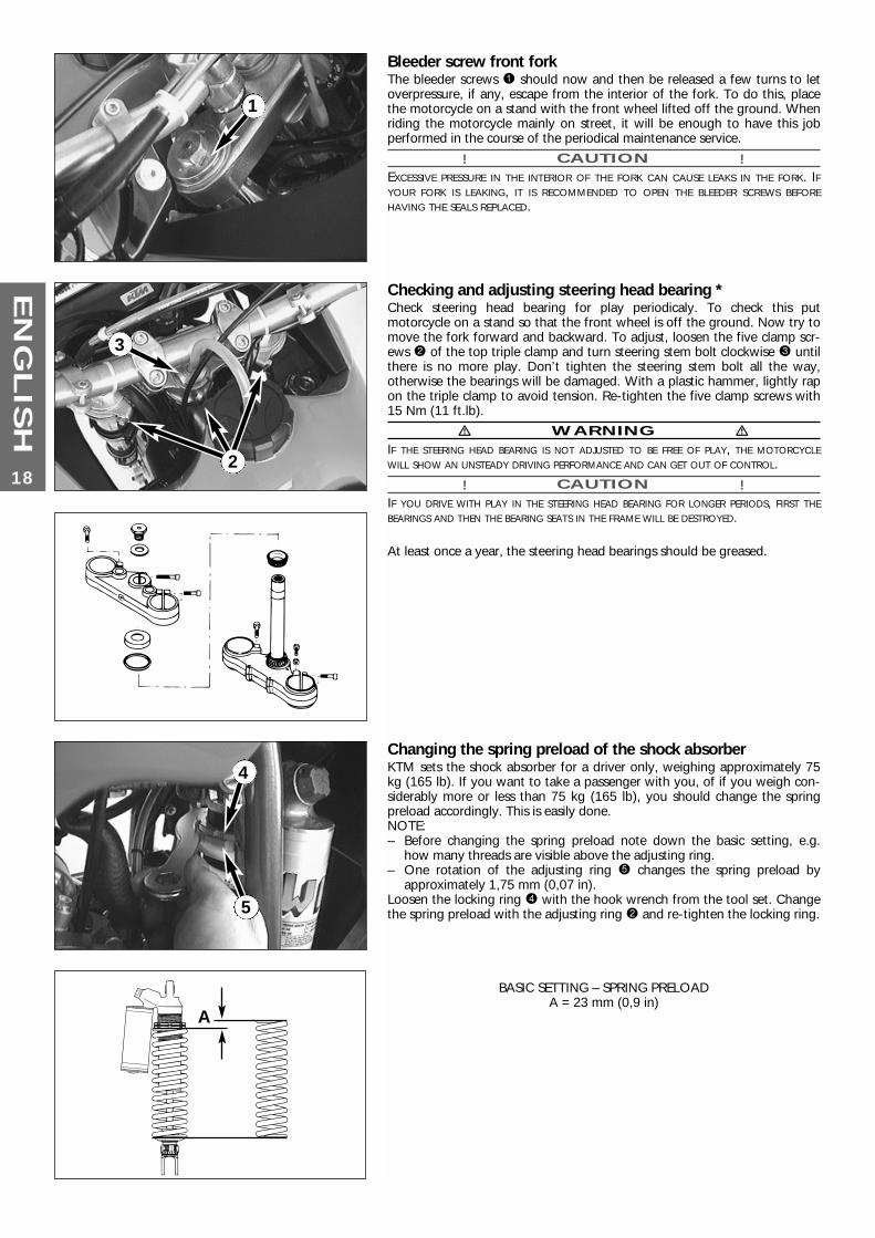
Bleeder screw front forkThe bleeder screws 1 should now and then be released a few turns to letoverpressure, if any, escape from the interior of the fork. To do this, placethe motorcycle on a stand with the front wheel lifted off the ground. Whenriding the motorcycle mainly on street, it will be enough to have this jobperformed in the course of the periodical maintenance service.
! CAUTION !EXCESSIVE PRESSURE IN THE INTERIOR OF THE FORK CAN CAUSE LEAKS IN THE FORK. IFYOUR FORK IS LEAKING, IT IS RECOMMENDED TO OPEN THE BLEEDER SCREWS BEFOREHAVING THE SEALS REPLACED.
Checking and adjusting steering head bearing *Check steering head bearing for play periodicaly. To check this putmotorcycle on a stand so that the front wheel is off the ground. Now try tomove the fork forward and backward. To adjust, loosen the five clamp scr-ews 2 of the top triple clamp and turn steering stem bolt clockwise 3 untilthere is no more play. Don’t tighten the steering stem bolt all the way,otherwise the bearings will be damaged. With a plastic hammer, lightly rapon the triple clamp to avoid tension. Re-tighten the five clamp screws with15 Nm (11 ft.lb).
� WARNING �IF THE STEERING HEAD BEARING IS NOT ADJUSTED TO BE FREE OF PLAY, THE MOTORCYCLEWILL SHOW AN UNSTEADY DRIVING PERFORMANCE AND CAN GET OUT OF CONTROL.
! CAUTION !IF YOU DRIVE WITH PLAY IN THE STEERING HEAD BEARING FOR LONGER PERIODS, FIRST THEBEARINGS AND THEN THE BEARING SEATS IN THE FRAME WILL BE DESTROYED.
At least once a year, the steering head bearings should be greased.
Changing the spring preload of the shock absorberKTM sets the shock absorber for a driver only, weighing approximately 75kg (165 lb). If you want to take a passenger with you, of if you weigh con-siderably more or less than 75 kg (165 lb), you should change the springpreload accordingly. This is easily done.NOTE:– Before changing the spring preload note down the basic setting, e.g.
how many threads are visible above the adjusting ring.– One rotation of the adjusting ring 5 changes the spring preload by
approximately 1,75 mm (0,07 in).Loosen the locking ring 4 with the hook wrench from the tool set. Changethe spring preload with the adjusting ring 2 and re-tighten the locking ring.
BASIC SETTING – SPRING PRELOADA = 23 mm (0,9 in)
A
4
5
1
2
3

EN
GLIS
H
19
Lubricating the shock absorber linkageThe bearings in the rocker arm must be greased in regular intervals. For thispurpose, a grease nipple 1 is mounted on the rocker arm.
! CAUTION !AFTER EACH TIME THE MOTORCYCLE IS WASHED, IT IS ESPECIALLY IMPORTANT TOGREASE THE GREASE NIPPLE TO PUSH ANY WATER OUT OF THE BEARINGS.
Checking chain tension– Support the motorcycle on the center stand or side stand, respectively.– Switch transmission to neutral.– Push the chain upwards appr. 30 mm (1,2 in) from the end of the chain sli-
ding component until the upper part of the chain is tensioned (see illustr.)– Now, the distance A between chain and swingarm should be 0 mm. The
upper part of the chain B must be tight (see illustr.).– Correct chain tension, if necessary!
� WARNING �– IF CHAIN TENSION IS TOO GREAT, PARTS WITHIN THE SECONDARY POWER TRANSMIS-
SION (CHAIN, CHAIN SPROCKETS, TRANSMISSION AND REAR WHEEL BEARINGS) WILL BESUBJECTED TO UNNECESSARY STRESS, RESULTING IN PREMATURE WEAR AND EVENCHAIN BREAKAGE.
– TOO MUCH SLACK IN THE CHAIN, ON THE OTHER HAND, CAN RESULT IN THE CHAINJUMPING OFF THE CHAIN WHEELS. IF THIS HAPPENS, THE CHAIN COULD ALSO BLOCKTHE REAR WHEEL OR DAMAGE THE ENGINE.
– IN EITHER CASE THE OPERATOR IS LIKELY TO LOSE CONTROL OF THE MOTORCYCLE.
Correct chain tension– Loosen collar nut 2, loosen counter nuts 3, and turn right and left adju-
sting screws 4 equally far. Tighten counter nuts 3. – Before tightening the wheel spindle, verify that the chain adjusters 5 are
sitting close to the adjusting screws and that the rear wheel has been ali-gned with the front wheel.
– Tighten collar nut 2 with 80 Nm (59 ft.lb).
A
B
15:4516:3816:40 A = 0 mm
16:45
30mm
1
5
2 3
4
5
EN
GLIS
H
20
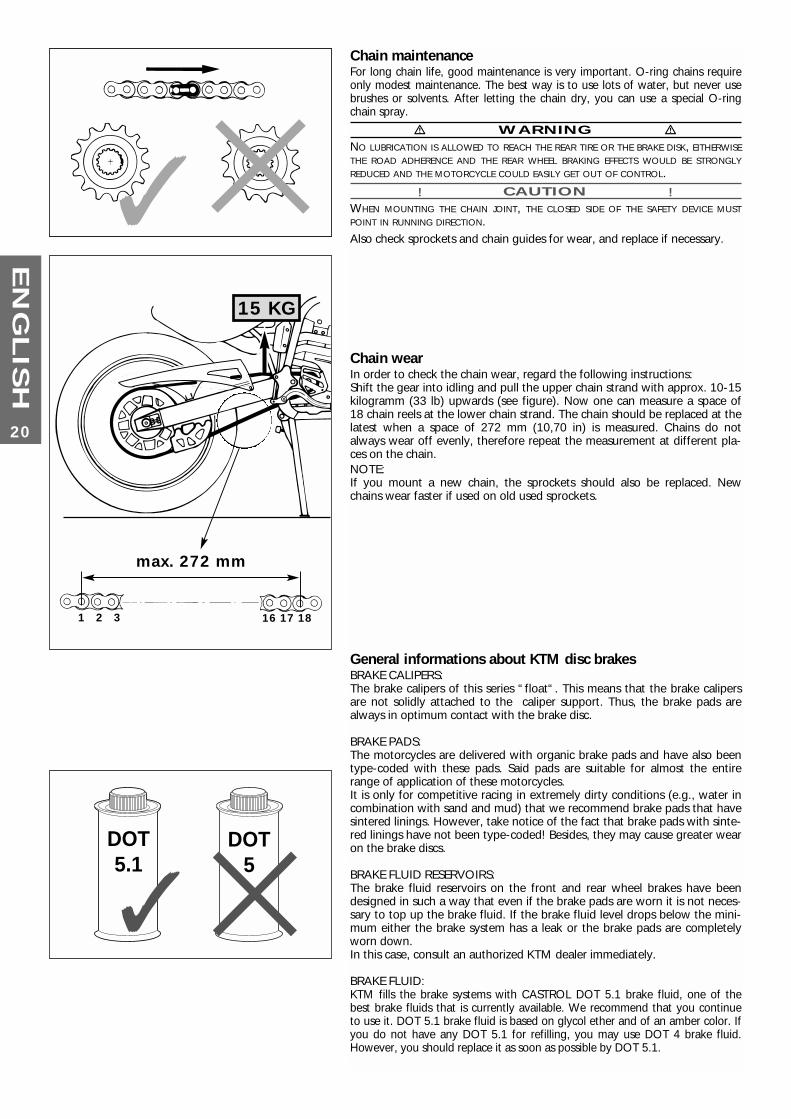
Chain maintenanceFor long chain life, good maintenance is very important. O-ring chains requireonly modest maintenance. The best way is to use lots of water, but never usebrushes or solvents. After letting the chain dry, you can use a special O-ringchain spray.
� WARNING �NO LUBRICATION IS ALLOWED TO REACH THE REAR TIRE OR THE BRAKE DISK, EITHERWISETHE ROAD ADHERENCE AND THE REAR WHEEL BRAKING EFFECTS WOULD BE STRONGLYREDUCED AND THE MOTORCYCLE COULD EASILY GET OUT OF CONTROL.
! CAUTION !WHEN MOUNTING THE CHAIN JOINT, THE CLOSED SIDE OF THE SAFETY DEVICE MUSTPOINT IN RUNNING DIRECTION.Also check sprockets and chain guides for wear, and replace if necessary.
Chain wearIn order to check the chain wear, regard the following instructions:Shift the gear into idling and pull the upper chain strand with approx. 10-15kilogramm (33 lb) upwards (see figure). Now one can measure a space of18 chain reels at the lower chain strand. The chain should be replaced at thelatest when a space of 272 mm (10,70 in) is measured. Chains do notalways wear off evenly, therefore repeat the measurement at different pla-ces on the chain.NOTE:If you mount a new chain, the sprockets should also be replaced. Newchains wear faster if used on old used sprockets.
General informations about KTM disc brakesBRAKE CALIPERS:The brake calipers of this series “float“. This means that the brake calipersare not solidly attached to the caliper support. Thus, the brake pads arealways in optimum contact with the brake disc.
BRAKE PADS:The motorcycles are delivered with organic brake pads and have also beentype-coded with these pads. Said pads are suitable for almost the entirerange of application of these motorcycles.It is only for competitive racing in extremely dirty conditions (e.g., water incombination with sand and mud) that we recommend brake pads that havesintered linings. However, take notice of the fact that brake pads with sinte-red linings have not been type-coded! Besides, they may cause greater wearon the brake discs.
BRAKE FLUID RESERVOIRS:The brake fluid reservoirs on the front and rear wheel brakes have beendesigned in such a way that even if the brake pads are worn it is not neces-sary to top up the brake fluid. If the brake fluid level drops below the mini-mum either the brake system has a leak or the brake pads are completelyworn down.In this case, consult an authorized KTM dealer immediately.
BRAKE FLUID:KTM fills the brake systems with CASTROL DOT 5.1 brake fluid, one of thebest brake fluids that is currently available. We recommend that you continueto use it. DOT 5.1 brake fluid is based on glycol ether and of an amber color. Ifyou do not have any DOT 5.1 for refilling, you may use DOT 4 brake fluid.However, you should replace it as soon as possible by DOT 5.1.
15 KG
max. 272 mm
1 2 3 16 17 18
DOT5.1
DOT5
✓ ✕
✓

EN
GLIS
H
21
Adjusting of free travel at the hand brake leverFree travel at the hand brake lever may be readjusted by using adjustingscrew 1. In this way, the position of the point of pressure (i.e., the resi-stance you feel on the hand brake lever when the brake pads are pressedagainst the brake disc) can be adjusted for any hand size.
! CAUTION !AT THE HAND BRAKE LEVER, FREE TRAVEL MUST AT LEAST BE 3 MM. ONLY THEN MAYTHE PISTON IN THE HAND BRAKE CYLINDER BE MOVED (TO BE RECOGNIZED BY THEGREATER RESISTANCE OF THE HAND BRAKE LEVER). IF THIS FREE TRAVEL IS NOT PROVI-DED, PRESSURE WILL BUILD UP IN THE BRAKING SYSTEM, AND THE FRONT WHEEL BRAKEMAY FAIL DUE TO OVERHEATING.
Checking of brake fluid level - front brakeThe brake fluid reservoir is linked with the hand brake cylinder at the hand-lebar and the reservoir is provided with an inspection glass. With the reser-voir in a horizontal position, the brake fluid level should not go belowmiddle of the glass.
� WARNING �IF THE BRAKE FLUID LEVEL DROPS BELOW THE MINIMUM EITHER THE BRAKE SYSTEM HASA LEAK OR THE BRAKE PADS ARE COMPLETELY WORN DOWN. IN THIS CASE, CONSULTAN AUTHORIZED KTM DEALER IMMEDIATELY.
Refilling the front brake fluid reservoir *Loosen screws 2 and remove lid 3 and membrane 4. Place hand brake cylinder in a horizontal position and fill the brake fluidreservoir to 5 mm (0,2 in) below the rim with brake fluid DOT 5.1. Replacemembrane and lid, tighten screws. Rinse off spilled or overflowing brakefluid with water.
� WARNING �– NEVER USE DOT5 BRAKE FLUID! IT IS BASED ON SILICONE OIL AND OF A PURPLE
COLOR. SEALS AND BRAKE HOSES MUST BE ESPECIALLY ADAPTED TO IT.– STORE BRAKE FLUID OUT OF REACH OF CHILDREN.– BRAKE FLUID CAN CAUSE SKIN IRRITATION. AVOID CONTACT WITH SKIN AND EYES. IF
YOU GET BRAKE FLUID IN YOUR EYES, RINSE WITH PLENTY OF WATER AND CONSULTA DOCTOR.
! CAUTION !– DON’T LET BRAKE FLUID GET IN CONTACT WITH PAINT, IT IS AN EFFECTIVE PAINT REMO-
VER.– USE ONLY CLEAN BRAKE FLUID TAKEN FROM A TIGHTLY SEALED CONTAINER.
Checking the front brake padsThe brake pads can be inspected from below. The linings must be at least 1mm (0,04 in) thick.
� WARNING �AT THEIR MOST WORN POINT BRAKE PAD LININGS SHOULD NOT BE THINNER THAN 1MM, OTHERWISE THEY COULD LEAD TO BRAKE FAILURE. FOR YOUR OWN SAFETY DON’TPUT OFF HAVING YOUR BRAKE PADS CHANGED.
! CAUTION !IF THE BRAKE PADS ARE REPLACED TOO LATE SO THAT THE LINING IS PARTLY OR ENTI-RELY WORN AWAY, THE STEEL COMPONENTS OF THE BRAKE PAD WILL RUB AGAINST THEBRAKE DISC, IMPAIRING THE BRAKING EFFECT AND DESTROYING THE BRAKE DISC.
min. 3 mm
5 mm
min.1 mm
2 23
4
1

EN
GLIS
H
22
Changing the basic position of the foot brake pedal *The basic position of the foot brake pedal can be altered by turning the stoproller 1. The free play at the foot brake pedal must then be adjusted by meansof the piston rod 2.Measured on the outside, the foot brake pedal must have 3-5 mm (0,12–0,20in) of free play, before the piston rod can move the piston in the brake cylinder(to be recognised from the resistance on the foot brake pedal).
! CAUTION !IF THIS FREE PLAY IS NOT PRESENT, THEN PRESSURE CAN BUILD UP IN THE BRAKE SYSTEM-WHEN DRIVING, CAUSING CONSTANT FRICTION OF THE BRAKE PADS.THE BRAKING SYSTEMOVERHEATS AND CAN FAIL COMPLETELY IN EXTREME CASES.
Checking rear brake fluid levelThe reservoir for the rear disc brake is located on the left-hand side of thevehicle next to the carburetor carburetor connection boot. The brake fluidlevel may not drop below the „MlN” marking when the vehicle is in anupright position.
� WARNING �IF THE BRAKE FLUID LEVEL DROPS BELOW THE MINIMUM EITHER THE BRAKE SYSTEM HAS ALEAK OR THE BRAKE PADS ARE COMPLETELY WORN DOWN. IN THIS CASE, CONSULT ANAUTHORIZED KTM DEALER IMMEDIATELY.
Refilling the rear brake fluid reservoir *When the brake fluid level has dropped to the MIN mark, you need to refillthe brake fluid reservoir.For better access to the brake fluid reservoir, remove the seat and the right sidecover. Remove plug 3 with rubber boot 4 and add brake liquid DOT 5.1 up tothe „MAX“ mark. Replace rubber boot and plug. Overflown or spilled brakeliquid must be rinsed off with water.
� WARNING �– NEVER USE DOT5 BRAKE FLUID! IT IS BASED ON SILICONE OIL AND OF A PURPLE
COLOR. SEALS AND BRAKE HOSES MUST BE ESPECIALLY ADAPTED TO IT.– STORE BRAKE FLUID OUT OF REACH OF CHILDREN.– BRAKE FLUID CAN CAUSE SKIN IRRITATION. AVOID CONTACT WITH SKIN AND EYES. IF YOU
GET BRAKE FLUID IN YOUR EYES, RINSE WITH PLENTY OF WATER AND CONSULT A DOCTOR
! CAUTION !– DON’T LET BRAKE FLUID GET IN CONTACT WITH PAINT, IT IS AN EFFECTIVE PAINT
REMOVER.– USE ONLY CLEAN BRAKE FLUID TAKEN FROM A TIGHTLY SEALED CONTAINER.
Checking the rear brake padsThe brake pads can be inspected from the rear. The thickness of the liningsmay not be less than 1 mm (0.04 in).
� WARNING �AT THEIR MOST WORN POINT BRAKE PAD LININGS SHOULD NOT BE THINNER THAN 1 MM,OTHERWISE THEY COULD LEAD TO BRAKE FAILURE. FOR YOUR OWN SAFETY DON’T PUT OFFHAVING YOUR BRAKE PADS CHANGED.
! CAUTION !IF THE BRAKE PADS ARE REPLACED TOO LATE SO THAT THE LINING IS PARTLY OR ENTIRELYWORN AWAY, THE STEEL COMPONENTS OF THE BRAKE PAD WILL RUB AGAINST THE BRAKEDISC, IMPARING THE BRAKING EFFECT AND DESTROYING THE BRAKE DISC.
min.1 mm
3
4
3-5mm
1
2

EN
GLIS
H
23
Dismounting and mounting the front wheel– To remove the front wheel, jack the motorcycle up on its frame so that
the front wheel no longer touches the ground.– Loosen the collar screw 1 and unscrew it approx. 5 turns.– Loosen the 4 clamping screws 2 on the fork leg axle passage.– Use the collar screw to push the wheel spindle forward and remove the
collar screw.– Hold the front wheel, pull out the wheel spindle 3
NOTICE: the wheel spindle may be pulled out more easily, if you slide anopen-end wrench (17mm) onto the flat portion of the wheel spindle.
– Remove front wheel carefully from the fork.
! CAUTION !DO NOT OPERATE THE HAND BRAKE WHEN THE FRONT WHEEL HAS BEEN DISMOUNTED.
– Before mounting, check if the left and the right 4 distance bushing arecorrectly positioned in the shaft seal rings. Extremely soiled distance bus-hings should be removed, cleaned and regreased.
– To mount the front wheel lift it into the fork and insert the brake diskinto the brake caliper.
– Position the front wheel and mount the wheel spindle.– Mount the collar screw 1 and tighten with 40 Nm (30 ft.Ibs).– Take the motorcycle off the stand and bounce the fork hard a few times
to align the fork legs– Then tighten clamping screws 5 to a max. torque of 10 Nm (7 ft.lbs)
� WARNING �– IF YOU DON’T HAPPEN TO HAVE A TORQUE WRENCH AT HAND, MAKE SURE YOU
HAVE THE TIGHTENING TORQUE CORRECTED BY A KTM DEALER AS SOON AS POSSI-BLE. A LOOSE AXLE MAY LEAD TO AN UNSTABLE DRIVING BEHAVIOR OF YOURMOTORCYCLE.
– AFTER MOUNTING THE FRONT WHEEL, KEEP OPERATING THE HAND BRAKE UNTIL THEPRESSURE POINT RETURNS.
– IT IS VERY IMPORTANT TO KEEP THE BRAKE DISK FREE FROM OIL AND FATTY MATTERS,EITHERWISE THE BRAKING EFFECTS WOULD BE STRONGLY REDUCED.
Dismounting and mounting the rear wheel*Jack the motorcycle up by frame so that the rear wheel no longer touchesthe ground. Loosen the collar nut 6, hold the rear wheel and pull out thewheel spindle 7 until the rear wheel is free but the brake caliper support isstill held. Push the rear wheel as far forward as possible, take the chain fromthe rear sprocket and carefully take the rear wheel out of the swingarm.
! CAUTION !– DO NOT OPERATE THE REAR BRAKE WHEN THE REAR WHEEL HAS BEEN DISMOUNTED.
IF THE AXLE IS DISMOUNTED, CLEAN THE THREAD OF THE WHEEL SPINDLE ANDCOLLAR NUT THOROUGHLY AND APPLY A NEW COAT OF GREASE TO PREVENT THETHREAD FROM JAMMING.
The rear wheel is remounted in reverse order. Before tightening the collarnut to 80 Nm (59 ft.lbs), push the rear wheel forwards so that the chaintensioners lie on the tension screws.
� WARNING �– IF YOU DON’T HAPPEN TO HAVE A TORQUE WRENCH AT HAND, MAKE SURE YOU
HAVE THE TIGHTENING TORQUE CORRECTED BY A KTM DEALER AS SOON AS POSSI-BLE. A LOOSE WHEEL SPINDLE MAY LEAD TO AN UNSTABLE DRIVING BEHAVIOR OFYOUR MOTORCYCLE.
– AFTER MOUNTING THE REAR WHEEL, KEEP OPERATING THE FOOTBRAKE UNTIL THEPRESSURE POINT RETURNS.
– IT IS VERY IMPORTANT TO KEEP THE BRAKE DISK FREE FROM OIL AND GREASE, OTHER-WISE THE BRAKING EFFECT WOULD BE STRONGLY REDUCED.
1
2
2
3
4
6
7
7

EN
GLIS
H
24
Checking the shock absorption rubbers in the rear hub*Some of the LC4 models have a cush-drive rear wheel hub. For this pur-pose, the engine power is conveyed from the rear sprocket via 6 shockabsorption rubbers 1 to the rear wheel. These 6 absorption rubbers wearwith increasing operation time, and should be checked for wear wheneverthe rear wheel is dismounted.
For this purpose, lie the rear wheel on a work bench with the rear sprocketupwards, and put the wheel spindle in the hub. Now hold the rear wheelfirmly and try to turn the rear sprocket. The rear sprocket may not turnmore than maximum 5 mm (0,2 in) measured on the outside. If the play inthe chain wheel is larger, all 6 shock absorption rubbers are to be replaced.Check the shock absorption rubbers for signs of damage and dirt.
! CAUTION !IF THE SHOCK ABSORPTION RUBBERS ARE NOT REPLACED IN GOOD TIME, THE REAR SPROCKETCARRIER AND THE REAR HUB WILL BE DAMAGED. ALLWAYS REPLACE ALL 6 ABSORPTION RUB-BERS, NEVER SINGLE RUBBERS.
Tires, air pressureTire type, tire condition, and how much air pressure the tires have in themaffect the way your motorcycle rides, and they must therefore be checkedwhenever you’re getting ready to go anywhere on your motorcycle.– Tire type and size can be found in the technical specifications and in the
homologation certificate– Tire condition has to be checked every time you want to ride your
motorcycle. Before leaving check for punctures and nails or other sharpobjects that might have become embedded in the tire. Refer to the specific regulations in your country for minimum tire treadrequirements. We recommend replacing tires at the latest when thetread is down to 2 mm.
– Tire pressure should be checked regularly on a “cold” tire. Proper pres-sure ensures optimum driving comfort and extends the life of your tires.
� WARNING �– DO NOT MOUNT TIRES WHICH HAVE NOT BEEN APPROVED BY KTM. OTHER TIRES
COULD HAVE ADVERSE EFFECTS ON THE WAY YOUR MOTORCYCLE RIDES.– THE FRONT AND REAR WHEEL ARE ONLY ALLOWED TO BE TIRED WITH TIRES THAT
HAVE THE SAME PROFILE TYPE.– FOR YOUR OWN SAFETY REPLACE DAMAGED TIRES IMMEDIATELY.– WORN TIRES CAN HAVE A NEGATIVE EFFECT ON HOW YOUR MOTORCYCLE PER-
FORMS, ESPECIALLY ON WET SURFACES– IF AIR PRESSURE IS TOO LOW, ABNORMAL WEAR AND OVERHEATING OF THE TIRE CAN
RESULT
Checking spoke tensionThe correct spoke tension is very important for the stability of the wheelsand thus for riding safety. A loose spoke causes the wheel to become unba-lanced and before long other spokes will have come loose. Check spoketension, especially on a new motorcycle, in regular intervals. For checking,tap on each spoke with the blade of a screw driver (see illustration). A cleartone must be the result. Dull tones indicate loose spokes. If necessary, havethe spokes retightened and the wheel centered by a KTM dealer.
� WARNING �SPOKES CAN TEAR IF YOU CONTINUE TO RIDE WITH THEM LOOSE. THIS MAY LEAD TO ANUNSTABLE HANDLING OF YOUR MOTORCYCLE.
front rear
Road driver only 1,5 bar (22 psi) 2,0 bar (29 psi)
Road w. passenger 2,0 bar (29 psi) 2,2 bar (31 psi)
TIRES - AIR PRESSURE
max 5 mm
1

EN
GLIS
H
25
BatteryThe battery is mounted under the seat (remove the seat, see page 17)The battery has a closed system and therefore requires no maintenance. It isnot necessary to check the electrolyte level or to refill water. Simply keepthe battery poles clean and slightly grease them with an acid-free grease ifnecessary.Removing the battery:– First disconnect the negative and then the positive pole of the battery.– Remove screws 1 and swing retaining bracket and voltage regulator out
of the way.– Remove battery.– When replacing, connect first the positive and then the negative pole.
� WARNING �– IF ELECTROLYTE (SULPHURIC ACID) LEAKS FROM THE BATTERY, PROCEED WITH GREAT
CARE. THE ELECTROLYTE CAN CAUSE SEVERE BURNS.– IN THE CASE OF SKIN CONTACT RINSE THOROUGHLY WITH WATER.– IN THE CASE OF CONTACT WITH THE EYES, THOROUGHLY RINSE EYES WITH WATER
FOR AT LEAST 15 MINUTES. IMMEDIATELY CONSULT A DOCTOR!– THE BATTERY IS A CLOSED MODEL BUT CAN NEVERTHELESS EMIT EXPLOSIVE GASES.
AVOID SPARKS AND OPEN FIRE NEAR THE BATTERY.– DEFECT BATTERIES MUST BE STORED OUT OF THE REACH OF CHILDREN. ENSURE PRO-
PER DISPOSAL OF DISCARDED BATTERIES.
! CAUTION !– TO AVOID DAMAGE, DO NOT REMOVE THE LOCKING BAR 2 !– NEVER DISCONNECT THE BATTERY WHILE THE ENGINE IS RUNNING. THIS WILL DEST-
ROY THE RECTIFIER-REGULATOR.
BATTERY STORAGE:When preparing the motorcycle for a longer period of standstill, remove thebattery and recharge it. Storage temperature: 0 - 35°C. Do not expose todirect sun radiation.
Charging the batteryRemove the battery and check the charging level. Use a voltmeter to mea-sure the voltage between the battery poles (off-load voltage).Accurate results can only be obtained if the battery has neither been char-ged nor discharged during a period of 30 minutes preceding the measuring.
If the battery is empty, it can be recharged for a maximum period of 10 hoursat 0.3 A and a maximum of 14.4 V.
! CAUTION !– TO AVOID DAMAGE, DO NOT REMOVE THE LOCKING BAR– ALWAYS CONNECT THE BATTERY TO THE CHARGING UNIT BEFORE TURNING THE
CHARGING UNIT ON.– WHEN RECHARGING THE BATTERY IN CLOSED ROOMS ENSURE SUFFICIENT VENTILA-
TION. EXPLOSIVE GASES ARE RELEASED DURING THE BATTERY CHARGING PROCESS.– CHARGING TIME AND CHARGING VOLTAGE SHOULD NOT EXCEED THE STATED VALUES.
OTHERWISE ELECTROLYTE WILL BE RELEASED THROUGH THE SAFETY VALVES.– AVOID QUICK CHARGING IF POSSIBLE.
off load voltage charging level charging time charging voltageVolt % 0,8 A
>12,7 100 ––~12,5 75 4 h
max.~12,2 50 7 h
14,4 V~12,0 25 11 h~11,8 0 14 h
VOLT
1
2

EN
GLIS
H
26
Main fuseLocated near the battery under the seat, the main fuse 1 protects all power consumers.Replace a blown fuse only with an equivalent one. If a new fuse that hasjust been set in gets blown again, you are strongly advised to have it ins-pected by a KTM dealer.The fuse capacity is 10 Ampere.
! CAUTION !UNDER NO CIRCUMSTANCES IS A STRONGER FUSE ALLOWED TO BE SET IN OR A FUSEALLOWED TO BE “REPAIRED”. AN INEXPERT TREATMENT COULD DAMAGE THE WHOLEELECTRICAL INSTALLATION!
Fuse / fanThe fan motor of the radiator is specially protected. The fuse 2 is locatedbehind the right radiator. It is visible through the right opening of the tankand can be accessed from below.Replace a blown fuse only with an equivalent one. If a new fuse that hasjust been set in gets blown again, you are strongly advised to have it ins-pected by a KTM dealer.Fuse capacity: 5 Ampere.
! CAUTION !UNDER NO CIRCUMSTANCES IS A STRONGER FUSE ALLOWED TO BE SET IN OR A FUSEALLOWED TO BE “REPAIRED”. AN INEXPERT TREATMENT COULD DAMAGE THE WHOLEELECTRICAL INSTALLATION!
Removing and mounting the headlight mask *The headlight mask must be removed to replace the headlight lamps, theindicator lamps or the tachometer lamps.
REMOVING THE HEADLIGHT MASK – Use the wrench from the tool kit to remove the 6 screws 3 of the head-
light mask.– Swing the headlight mask forward, disconnect the flasher cables and
remove the mask.
MOUNTING THE HEADLIGHT MASK – Hold the headlight mask and connect the flasher cables. – Position the headlight mask and replace the screws without tightening
them yet.– Tighten all 6 screws at once with 5 Nm (4 ft.Ibs).
Replacing the headlight bulb *The headlights are accessible after you have removed the headlight mask.– Turn the cover 4 counterclockwise, and remove it.– Detach the spring bar 5, and remove the lamp from the headlight– insert and connect a new H1 lamp (12 V 55 W)
! CAUTION !THE GLASS OF THE BULB MUST BE FREE OF OIL AND GREASE. THE HEAT CAUSES THEOIL TO VAPORIZE. THE RESULTING VAPOR ON THE REFLECTOR DECREASES THEBRIGHTNESS OF THE HEADLIGHT.
– Start the engine and check the headlight for proper functioning.– Place the cover in position, and turn it clockwise.
2
3
3
1
4
5
EN
GLIS
H
27
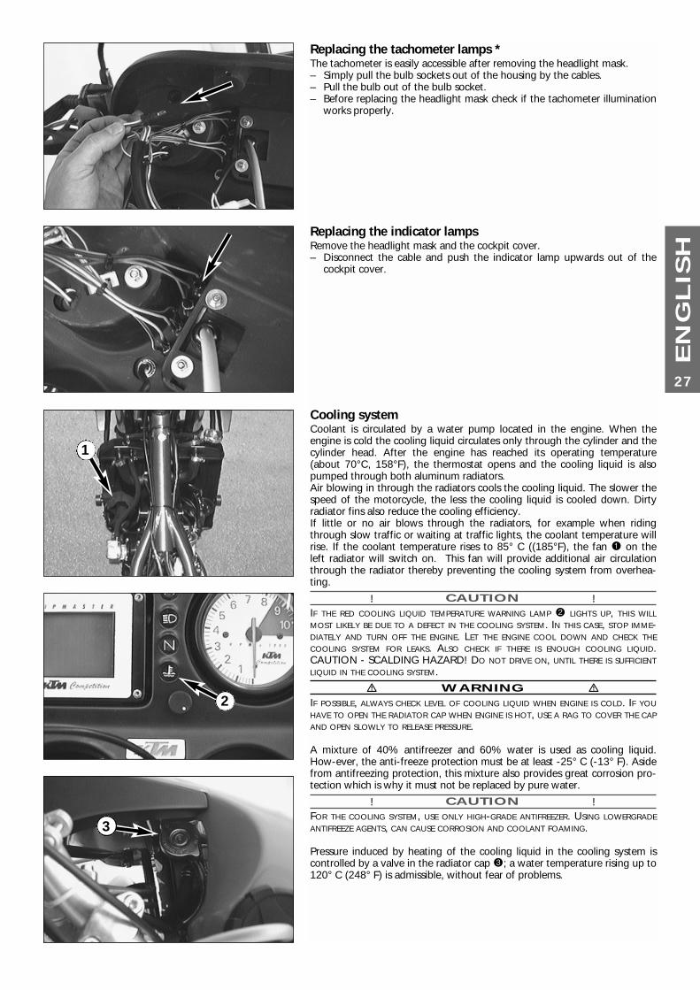
Replacing the tachometer lamps *The tachometer is easily accessible after removing the headlight mask.– Simply pull the bulb sockets out of the housing by the cables. – Pull the bulb out of the bulb socket.– Before replacing the headlight mask check if the tachometer illumination
works properly.
Replacing the indicator lampsRemove the headlight mask and the cockpit cover. – Disconnect the cable and push the indicator lamp upwards out of the
cockpit cover.
Cooling systemCoolant is circulated by a water pump located in the engine. When theengine is cold the cooling liquid circulates only through the cylinder and thecylinder head. After the engine has reached its operating temperature(about 70°C, 158°F), the thermostat opens and the cooling liquid is alsopumped through both aluminum radiators.Air blowing in through the radiators cools the cooling liquid. The slower thespeed of the motorcycle, the less the cooling liquid is cooled down. Dirtyradiator fins also reduce the cooling efficiency.If little or no air blows through the radiators, for example when ridingthrough slow traffic or waiting at traffic lights, the coolant temperature willrise. If the coolant temperature rises to 85° C ((185°F), the fan 1 on theleft radiator will switch on. This fan will provide additional air circulationthrough the radiator thereby preventing the cooling system from overhea-ting.
! CAUTION !IF THE RED COOLING LIQUID TEMPERATURE WARNING LAMP 2 LIGHTS UP, THIS WILLMOST LIKELY BE DUE TO A DEFECT IN THE COOLING SYSTEM. IN THIS CASE, STOP IMME-DIATELY AND TURN OFF THE ENGINE. LET THE ENGINE COOL DOWN AND CHECK THECOOLING SYSTEM FOR LEAKS. ALSO CHECK IF THERE IS ENOUGH COOLING LIQUID.CAUTION - SCALDING HAZARD! DO NOT DRIVE ON, UNTIL THERE IS SUFFICIENTLIQUID IN THE COOLING SYSTEM.
� WARNING �IF POSSIBLE, ALWAYS CHECK LEVEL OF COOLING LIQUID WHEN ENGINE IS COLD. IF YOUHAVE TO OPEN THE RADIATOR CAP WHEN ENGINE IS HOT, USE A RAG TO COVER THE CAPAND OPEN SLOWLY TO RELEASE PRESSURE.
A mixture of 40% antifreezer and 60% water is used as cooling liquid.How-ever, the anti-freeze protection must be at least -25° C (-13° F). Asidefrom antifreezing protection, this mixture also provides great corrosion pro-tection which is why it must not be replaced by pure water.
! CAUTION !FOR THE COOLING SYSTEM, USE ONLY HIGH-GRADE ANTIFREEZER. USING LOWERGRADEANTIFREEZE AGENTS, CAN CAUSE CORROSION AND COOLANT FOAMING.
Pressure induced by heating of the cooling liquid in the cooling system iscontrolled by a valve in the radiator cap 3; a water temperature rising up to120° C (248° F) is admissible, without fear of problems.
1
2
3

EN
GLIS
H
28
Checking the cooling liquid levelThe cooling liquid should be 10 mm (0,4 in) above the cooling elementswhen the engine is cold (cf. diagram). In the event of the cooling liquidbeing drained, always fill the system before hand, then top off while theengine is running.
� WARNING �IF POSSIBLE, ALWAYS CHECK LEVEL OF COOLING LIQUID WHEN ENGINE IS COLD. IF YOUHAVE TO OPEN THE RADIATOR CAP WHEN ENGINE IS HOT, USE A RAG TO COVER THE CAPAND OPEN SLOWLY TO RELEASE PRESSURE.
Adjust idling speed *Idling adjustment of the carburetor strongly affects the engine’s startingbehavior. That is, an engine whose idling speed is adjusted correctly will beeasier to start than one whose idling speed has not been adjusted correctly.The throttle stop screw 1 is used to adjust the basic position of the slide.Turning in clockwise direction will increase the idling speed, turning incounterclockwise direction will reduce the idling speed. Normal idling speed1400 - 1500 rpm.The mixture control screw 2 never should be changed.
Adjusting the throttle cable *There must always be a 3-5 mm (0.1-0.2 in) play in the throttle cable. Tocheck this, move back the protective cover 3 on the throttle grip. You mustbe able to lift the outer covering of the cable 3-5 mm from the adjustingscrew 4, until resistance is felt.To adjust, loosen the counter nut 5 and turn the adjusting screw accordingly.Finally tighten counter nut and slide the protective cover back on.
Adjusting the choke cable *At the choke cable, there must always exist a play of approx. 2 mm (0.1 in).To check this, push choke lever fully forward and pull protective cover 6 fromthe adjuster piece 7. Now, it must be possible to lift the outer covering of thecable by approx. 2 mm from the adjuster piece until feeling a resistance. Ifnecessary, loosen counter nut and readjust play by turning the adjuster piece.Tighten counter nut, and slide on protective cover.
Adjusting the clutch cableWhen the engine is cold, the play at the clutch lever should be 10 mm (0.4 in)(measured at the outer edge).To adjust the clutch cable turn the adjusting nut 8 accordingly.
when engine is cold
10 mm
2 mm
1–3 mm
3-5 mm
21
345
67
8

EN
GLIS
H
29
Checking the adjustment of the hand decompression cable *To check, set piston at compression, so that the valves are closed. Whiledoing this, slowly operate the kickstarter through its stroke until the clickingsound (disengaging) of the automatic decompression can be heard. Nowthe decompression lever must be operated 25 mm (1 in) until resistance isfelt (the exhaust valves begin to open). To adjust move back the protectivecover 1, loosen the counter nut 2 and correct the adjusting screw 3 accor-dingly. Tighten counter nut and push back protective cover.
! CAUTION !IF THERE IS NO PLAY IN THE DECOMPRESSION LEVER, THIS CAN RESULT IN ENGINE DAMAGE.
NOTE:No adjustment need be made to the automatic decompressor.
Engine oilOnly use high-quality oils meeting or surpassing the quality requirements ofAPI classes SF, SG, or SH (for specifications see containers). You may useeither mineral oils or synthetic oils fulfilling the above criteria.
! CAUTION !INSUFFICIENT OIL OR POOR QUALITY OIL RESULTS IN PREMATURE WEAR OF THE ENGINE.
Checking engine oil levelAllow the engine to run at idle speed for about 4 minutes. Turn off theengine and place the motorcycle on a flat, level surface (main stand). Takeout the oil dipstick and wipe it off with a cloth. TWIST THE OIL DIPSTICK ALL THE WAY IN AND THEN RETRIEVE IT.The oil level should be between the two marks on the dipstick. Add engineoil if necessary.
! CAUTION !– INSUFFICIENT OIL OR POOR QUALITY OIL RESULTS IN PREMATURE WEAR OF THE
ENGINE.– CHECKING THE ENGINE OIL LEVEL WHEN THE ENGINE IS COLD RESULTS IN A FALSE
READING ON THE OIL DIPSTICK AND THEREFORE AN INCORRECT OIL LEVEL.– DO NOT OVERFILL THE ENGINE CASE.– DO NOT UNDERFILL THE ENGINE CASE.Check the engine for leaks.
Oil circuitThe oil pump 1 pumps the engine oil past the by-pass valve 2 through theoil filter 3. After the oil filter, an oil line branches off to a jet 4 whichsprays engine oil onto the piston pin bearing and piston head. The secondoil line takes the main flow of oil into the front pipe of the frame 5, wherethe engine oil is cooled down. Afterwards the engine oil runs through thefine screen filter 6, which filters out even the finest impurities. The cleanedengine oil is pumped through the oil line and the clutch cover into thecrankshaft to the conrod bearing 7 and drips into the crankcase. An addi-tional oil pump 8 sucks the engine oil out of the crankcase and pumps itthrough the oil line 9 to the gear wheels of the 4th and 5th gear. Via thegear wheels, the engine oil reaches the oil sump. The timing chain bk runsthrough the oil sump and transports the engine oil upwards to the cylinderhead. Through the bore hole bl the oil reaches the camshaft bm and thevalves.
� �– +0°C32°F
15W 4015W 5015W 60
10W 4010W 5010W 60
API: SF, SG, SH
TEMPERATURE
25 mm
8
7
1
23
4
5
6
9
10
1211
MAX
MIN
2
1
3
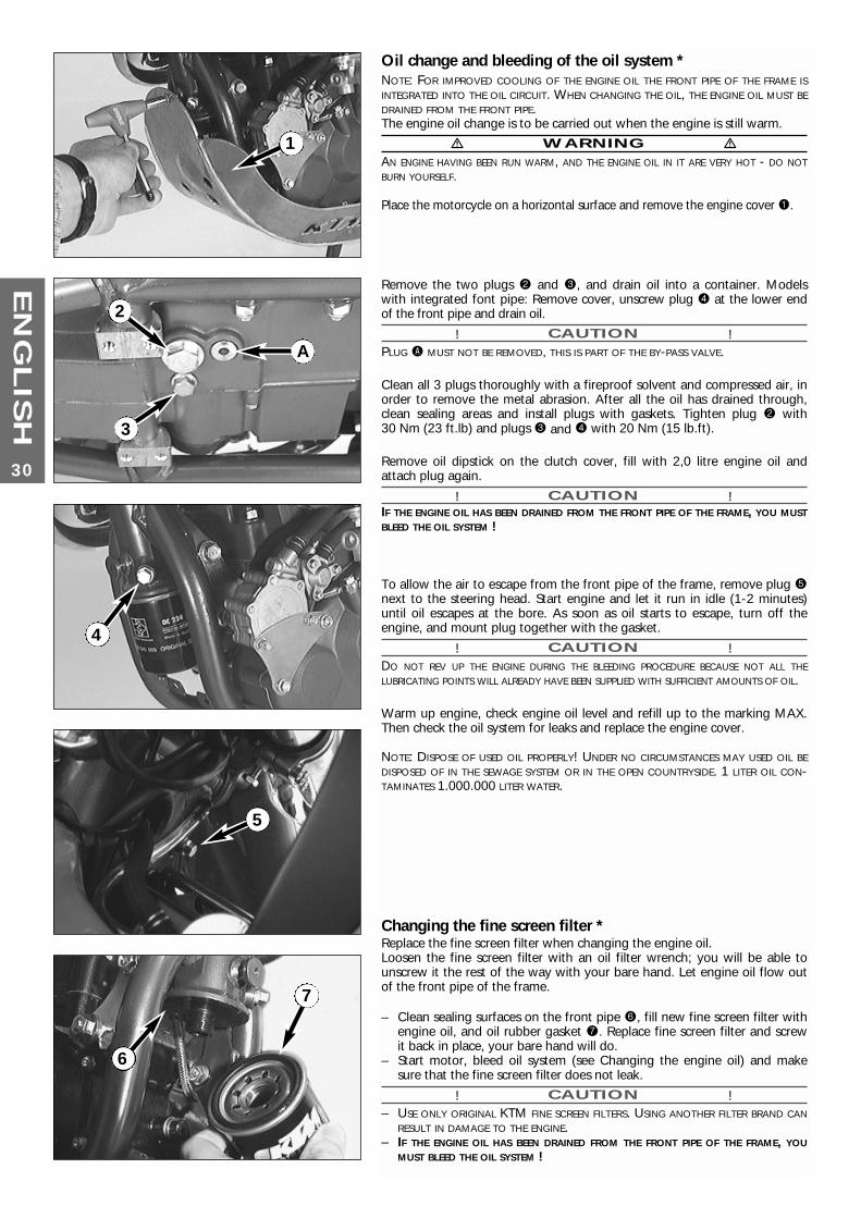
EN
GLIS
H
30
Oil change and bleeding of the oil system *NOTE: FOR IMPROVED COOLING OF THE ENGINE OIL THE FRONT PIPE OF THE FRAME ISINTEGRATED INTO THE OIL CIRCUIT. WHEN CHANGING THE OIL, THE ENGINE OIL MUST BEDRAINED FROM THE FRONT PIPE.The engine oil change is to be carried out when the engine is still warm.
� WARNING �AN ENGINE HAVING BEEN RUN WARM, AND THE ENGINE OIL IN IT ARE VERY HOT - DO NOTBURN YOURSELF.
Place the motorcycle on a horizontal surface and remove the engine cover 1.
Remove the two plugs 2 and 3, and drain oil into a container. Modelswith integrated font pipe: Remove cover, unscrew plug 4 at the lower endof the front pipe and drain oil.
! CAUTION !PLUG A MUST NOT BE REMOVED, THIS IS PART OF THE BY-PASS VALVE.
Clean all 3 plugs thoroughly with a fireproof solvent and compressed air, inorder to remove the metal abrasion. After all the oil has drained through,clean sealing areas and install plugs with gaskets. Tighten plug 2 with 30 Nm (23 ft.lb) and plugs 3 and 4 with 20 Nm (15 lb.ft).
Remove oil dipstick on the clutch cover, fill with 2,0 litre engine oil andattach plug again.
! CAUTION !IF THE ENGINE OIL HAS BEEN DRAINED FROM THE FRONT PIPE OF THE FRAME, YOU MUST
BLEED THE OIL SYSTEM !
To allow the air to escape from the front pipe of the frame, remove plug 5next to the steering head. Start engine and let it run in idle (1-2 minutes)until oil escapes at the bore. As soon as oil starts to escape, turn off theengine, and mount plug together with the gasket.
! CAUTION !DO NOT REV UP THE ENGINE DURING THE BLEEDING PROCEDURE BECAUSE NOT ALL THELUBRICATING POINTS WILL ALREADY HAVE BEEN SUPPLIED WITH SUFFICIENT AMOUNTS OF OIL.
Warm up engine, check engine oil level and refill up to the marking MAX.Then check the oil system for leaks and replace the engine cover.
NOTE: DISPOSE OF USED OIL PROPERLY! UNDER NO CIRCUMSTANCES MAY USED OIL BEDISPOSED OF IN THE SEWAGE SYSTEM OR IN THE OPEN COUNTRYSIDE. 1 LITER OIL CON-TAMINATES 1.000.000 LITER WATER.
Changing the fine screen filter *Replace the fine screen filter when changing the engine oil. Loosen the fine screen filter with an oil filter wrench; you will be able tounscrew it the rest of the way with your bare hand. Let engine oil flow outof the front pipe of the frame.
– Clean sealing surfaces on the front pipe 6, fill new fine screen filter withengine oil, and oil rubber gasket 7. Replace fine screen filter and screwit back in place, your bare hand will do.
– Start motor, bleed oil system (see Changing the engine oil) and makesure that the fine screen filter does not leak.
! CAUTION !– USE ONLY ORIGINAL KTM FINE SCREEN FILTERS. USING ANOTHER FILTER BRAND CAN
RESULT IN DAMAGE TO THE ENGINE.– IF THE ENGINE OIL HAS BEEN DRAINED FROM THE FRONT PIPE OF THE FRAME, YOU
MUST BLEED THE OIL SYSTEM !
4
1
2
3
A
5
6
7

EN
GLIS
H
31
Changing oil filter *Replace the oil filter when changing the engine oil. Press the foot brake pedaland place a screwdriver or similar between foot brake pedal and stopper roll sothat the oil filter cover is more accessible. Remove banjo bolt 1 and the threescrews. Remove oil filter cover 2 and oil filter. Clean filter housing, oil filtercover, and sealing surfaces. Check oil duct in oil filter cover if clogged.
Check the O-ring 3 for damage. O-rings need not be replaced unless damaged.Press the O-ring into the groove of the filter cover. Fit new oil filter 4 with rub-ber gasket on the fitting in oil filter cover and mount cover with filter. Mountthree screws and tighten with 5 Nm (4 ft.lb). Mount hollow screw with sealrings and tighten with 15 Nm (11 ft.lb). Start engine and check oil system forleakage.
1
2
3
4
21

EN
GLIS
H
32
TROUBLE SHOOTING
If you let the specified maintenance work on your motorcycle be carried out, disturbances can hardly be expected. Should an erroroccur nevertheless, we advise you to use the trouble shooting chart in order to find the cause of error.We would like to point out that many operations cannot be performed by oneself. In case of uncertainty, please contact a KTM-dealer.
TROUBLE
Engine doesn’t crank.
Engine doesn’t crank; neu-tral indicator lamp and head-light don’t light up.
The engine cranks only withpulled clutch lever
Engine cranks with gearengaged
Engine cranks but doesn’tstart.
CAUSE
Operating errror
Discharged battery.
Defect ignition lock or emergencyOFF switch
Blown main fuse
Discharged battery.
The diode at the connector supportis defect (interrupted)
Defect safe-starting system.
Operating error
Fuel supply interrupted
Defective fuel pump
Flooded engine
Sooty or wet spark plug
Electrode gap too large
Spark plug connector or spark plugfaulty
The plug connection of the CDI-unit, the pulse generator or theignition coil has oxydized
Water in carburetor or jets blocked
Carburetor does not fit in properlyat intake flange
REMEDY
Turn on the ignition, switch the gear to neutral and switch theemergency OFF switch on.
Starting see driving instruction page 14. Recharge the batteryand investigate the causes for discharging; contact a KTM dealer.
Check ignition lock and emergency OFF switch, contact aKTM dealer.
Remove seat and replace the main fuse. If fuse blows againcontact a KTM dealer
Starting see driving instruction page 14. Recharge the battery and investigate the causes for discharging; contact a KTM dealer.
Contact a KTM dealer; the diode must be replaced.
Contact a KTM dealer.
Open the fuel tap (see page 9), refuel. The choke or hot startdevice, respectively, has not been operated. Observe startinginstructions (see driving instructions).
Disconnect the fuel hose coming from the fuel tap at the fuelpump. Put the end of the fuel hose into an appropriate contai-ner and open the fuel tap. – If fuel flows out, check the fuel pump. – If no fuel flows out, the fuel evaporation control system must
be checked or the fuel tap must be cleaned, respectively.
Disconnect the fuel hose at the carburetor. Put the end of thefuel hose into an appropriate container, open the fuel taps andstart the engine. – If fuel flows out, clean the carburetor. – If no fuel flows out
– check the underpressure tube between the cylinder headand the fuel pump for leaks.
– check if the fuel filter is clogged. – contact a KTM dealer.
See driving instructions
Clean or replace spark plug
Adjust spark plug elektrode gap to 0,7 mm
Dismount spark plug, connect ignition cable, hold to ground(blank place on engine) and actuate starter, a strong sparkmust be produced at the spark plug– If no spark is produced, loosen spark plug cap from ignition
cable, hold about 5 mm from ground and actuate kickstarter– If a spark now occurs, replace spark plug cap– If no spark is produced, control ignition system
Remove the seat, the right side cover and the fuel tank. Cleanthe plug connection and treat it with contact spray
Dismount and clean carburetor
Check if carburetor is fitted in correctly

EN
GLIS
H
33
TROUBLE
Engine fails to idle
Engine does not rev high
Engine will not reach fullpower
Engine misfires or backfiresinto carburetor
Engine overheats
High oil consumption
All switched on lamps blown out
The NEUTRAL lamp is noton even though the gear isin NEUTRAL
CAUSE
Glogged idling jet
Oncorrect adjustment of adjusting screws on carburetor
Defective ignition system
Carburetor fuel level too high because– Float needle is dirty or worn out– Float leaks– Float has no axial play
Loose carburettor jets
Electronic ignition timing faulty
Fuel supply partically interrupted orcarburetor dirty
Float leaks, or no axial play
Air filter very dirty
Exhaust system leaking or deformed
Valve clearance to small
Loss of compression because handdecompressor has no play
Electronic ignition timing faulty
Fuel shortage
Engine takes in unmetered air
Insufficient cooling liquid
Radiator fins are extremely dirty
Foam forms in cooling system
Bent radiator hose
Thermostat defective
Blown fan fuse
Defect thermoswitch
Fan defective
Buckling gear ventilation hose
Engine oil level too high
Engine oil too thin (viscosity)
Voltage regulator faulty
Defect indicator lamp.
Defect neutral switch.
Loose connections, defect cable.
REMEDY
Disassemble carburetor and clean jets
Have carburetor adjusted
Have ignition system checked
Dismount carburetor and check if worn out Replace float needleReplace floatAbrade float
Tighten jets
Have ignition system checked
Clean and check fuel system as well as carburetor
Replace or abrade the float
Clean or replace air filter, contact a KTM dealer
Check if exhaust system is damaged
Have valve clearance adjusted
Check setting of the hand decompression cable
Have ignition system checked
Clean and check fuel system and carburettor
Check intake flange and carburettor for tight fit
Refill cooling liquid (see maintenace work), check coolingsystem for leaks
Clean radiator with water jet
Replace cooling liquid, use antifreezer with brand name
Shorten or replace cooling hose
Remove and check thermostat (opening temperature 70°C(158°F) or replace it, contact a KTM dealer
Replace fuse and check if fan operates properly (see below)
Contact a KTM dealer
Check if fan operates properly. To do this, start the engine,then bypass the connections to the thermoswitch (bottomright radiator), contact a KTM dealer
Readjust or replace ventilation hose
Check engine oil level when the engine is warm; correct if necessary
Use thicker engine oil; see chapter „Engine oil“
Remove seat and check connections. Have voltage regulator checked
Replace indicator lamp
Connect cable to ground; neutral switch must be replaced ifindicator lamp lights up.
Check connections and cables.
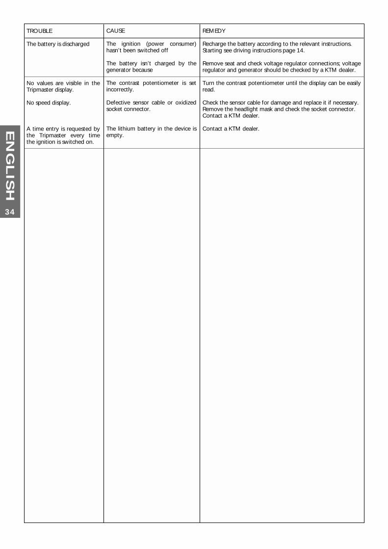
EN
GLIS
H
34
TROUBLE
The battery is discharged
No values are visible in theTripmaster display.
No speed display.
A time entry is requested bythe Tripmaster every timethe ignition is switched on.
CAUSE
The ignition (power consumer)hasn’t been switched off
The battery isn’t charged by thegenerator because
The contrast potentiometer is setincorrectly.
Defective sensor cable or oxidizedsocket connector.
The lithium battery in the device isempty.
REMEDY
Recharge the battery according to the relevant instructions.Starting see driving instructions page 14.
Remove seat and check voltage regulator connections; voltageregulator and generator should be checked by a KTM dealer.
Turn the contrast potentiometer until the display can be easilyread.
Check the sensor cable for damage and replace it if necessary.Remove the headlight mask and check the socket connector.Contact a KTM dealer.
Contact a KTM dealer.

EN
GLIS
H
35
Clean your motorcycle regularly in order to maintain the beauty of its plastic surfaces.The best manner would be to use warm water that has been mixed with a normal trade washing detergent and a sponge. The harddirt can be removed before with the help of a soft water jet.
! CAUTION !NEVER CLEAN YOUR MOTORCYCLE WITH A HIGH-PRESSURED CLEANER OR A HIGH-PRESSURED WATER JET. THE WATER COULD OTHERWISE RUN INTO THE ELEC-TRICAL COMPONENTS, CONNECTORS, SHEATHED CABLES, BEARINGS, CARBURETOR ETC. AND CAUSE DISTURBINGS OR LEAD TO A PREMATURE DESTRUCTION OFTHESE PARTS.
– You should use normal trade-mark detergents to clean the engine. Strongly dirted parts should be cleaned additionally with thehelp of a paint brush.
– After the motorcycle has been rinsed with a soft water jet, it should be dried by air pressure and a cloth. Then take a short driveuntil the engine has reached the working temperature and also use the brakes. Due to the heat, the water also evaporates at theunapproachable parts of the engine and the brakes.
– Slide back the protective covers on the handlebar-mounted instruments so that any water that may have seeped into this part ofthe motorcycle is allowed to evaporate.
– After the motorcycle has cooled down, oil and grease all sliding and pivot points. Treat the chain with a chain spray too.– To prevent failures in the electric system, you should treat the ignition lock, the emergency OFF switch, light switch and the socket
connectors with contact spray.
Should you desire to make a pause over a longer space of time, please observe the following instructions:– Clean motorcycle thoroughly (see chapter: CLEANING)– Change engine oil, oil filter and fine screen filter (old engine oil contains aggressive contaminations).– Check antifreezer and amount of cooling liquid.– Let the engine warm up again, close fuel tap and wait until the engine dies off by itself. By this means, carburetor jets are prevented
from becoming resinous by the old fuel.– Remove spark plug and fill in approx. 5 ccm of engine oil into the cylinder through the opening. Actuate kick-starter 10 times in
order to distribute the oil onto the cylinder walls and mount the spark plug.– Set piston to compression so that the valves will be closed (slowly operate the kickstarter, until you can hear the automatic decom-
pressor click (release))– Let fuel flow out of tank into an appropriate container.– Correct tire pressure.– Lubricate pivot points of the control levers, foot rests, etc. as well as the chain.– Service the shock absorber linkage– Disassemble and charge battery (see chapter: BATTERY).– The storage place should be dry and not subject to excessive temperature fluctuations.– Cover the motorcycle with an air permeated tarpaulin or blanket. Do not use non air permeable materials as a possible humidity
might not be able to escape and could cause corrosion.
! CAUTION !IT WOULD BE VERY BAD TO LET THE ENGINE RUN FOR A SHORT TIME DURING THE STORAGE PERIOD. THE ENGINE WOULD NOT GET WARMED UP ENOUGHAND THE THUS DEVELOPED STEAM WOULD CONDENSE DURING THE COMBUSTION PROCESS AND CAUSE THE VALVES AND EXHAUST TO RUST.
RE-INITIATION AFTER TIME OF STORAGE– Mount the charged battery (regard polarity).– Fill up tank with fresh fuel.– Check motorcycle as before each start (see driving instructions)– Take a short, careful test ride first.
CLEANING
STORAGE
In the event that the motorcycle is also used in winter and on roads where one has to expect salt spraying, you will have to take pre-cautions against the aggressive road salt.– Thoroughly clean and let the motorcycle dry after every ride.– Treat engine, carburetor, swing arm, and all other bare or galvanized parts (except for brake discs) with a wax-based anti-corrosion agent.
� WARNING �KEEP ANTI-CORROSION AGENT FROM GETTING INTO CONTACT WITH THE BRAKE DISCS, FOR OTHERWISE THIS WILL SIGNIFICANTLY REDUCE THE BRAKING POWER.
! CAUTION !AFTER RIDES ON SALTED ROADS, CLEAN MOTORCYCLE THOROUGHLY WITH COLD WATER AND LET IT DRY WELL!
CONSERVATION FOR WINTER OPERATION

EN
GLIS
H
36 Cra
nk s
haft
axia
l pla
y...
......
......
......
0,03
- 0
,12
mm
(0,
0012
- 0
,004
7 in
)
run
out
of c
rank
stu
d...
......
......
....m
ax. 0
,08
mm
(0,
0031
in)
Con
nect
ing
rod
bear
ing
radi
al p
lay
......
......
......
......
......
......
..max
. 0,0
5 m
m (
0,00
2 in
)
axia
l pla
y...
......
......
......
......
......
......
max
. 1,1
0 m
m (
0,04
3 in
)
Cyl
inde
rbo
re d
iam
eter
......
......
......
......
..max
. 101
,04
mm
(3,
9779
in)
Pist
onas
sem
bly
clea
ranc
e...
......
......
......
.max
. 0,1
2 m
m (
0,00
47 in
)
Pist
on r
ings
end
gap
com
pres
sion
rin
gs...
......
......
......
...m
ax. 0
,80
mm
(0,
0315
in)
oil s
crap
er r
ing
......
......
......
......
......
.max
. 1,0
mm
(0,
0394
in)
Val
ves
seat
sea
ling
inta
ke...
......
......
......
...m
ax. 1
,50
mm
(0,
0591
in)
seat
sea
ling
exha
ust.
......
......
......
..max
. 2,0
0 m
m (
0,07
88 in
)
run
out
of v
alve
hea
ds...
......
......
..max
. 0,0
5 m
m (
0,00
19 in
)
valv
e gu
ides
dia
met
er...
......
......
...m
ax. 7
,05
mm
(0,
2778
in)
Oil
pum
pcl
eara
nce
oute
r rot
or -
hou
sing
......
.max
. 0,2
0 m
m (
0,00
79 in
)
clear
ance
out
er ro
tor -
inne
r rot
or...
...m
ax. 0
,20
mm
(0,
0079
in)
Bypa
ß va
lve
min
imum
spr
ing
leng
ht...
......
......
......
......
...25
mm
(0,
985
in)
Clu
tch
clut
chsp
ring
leng
ht...
.min
. 34,
5 m
m (1
,36
in),
new
37
mm
(1,4
58 in
)
Wea
r lim
it or
gani
c....
......
......
......
......
min
. 2,5
mm
(0,
0985
in)
Cam
sha
ftdi
amet
er o
f be
arin
g bo
lt...
......
....m
in. 1
9,97
mm
(0,
7868
in)
(nee
dle
bear
ing)
Tran
smis
sion
sha
fts
axia
l pla
y...
......
......
......
...0,
1 –
0,4
mm
(0,
0039
– 0
,015
8 in
)
ASS
EMB
LY C
LEA
RA
NC
E, W
EAR
LIM
IT
TEC
HN
ICA
L D
ATA
– E
NG
INE
640
LC
4-E
AD
VEN
TUR
E R
‘98
Engi
ne64
0 LC
4-E
Des
ign
Liqu
id-c
oole
d si
ngle
cyl
inde
r 4-
stro
ke e
ngin
e w
ith b
alan
cer
shaf
t an
d el
ectr
ic s
tart
er
Dis
plac
emen
t62
5 cc
m
Bore
/St
roke
101
/ 78
mm
Rat
io11
,0 :
1
Fuel
unle
aded
pre
miu
m g
asol
ine
with
a le
ast
RO
N95
Val
ve t
imin
g4
valv
es o
ver
rock
er a
rm a
nd 1
ove
rhea
d ca
msh
aft,
cam
shaf
t dr
ive
thro
ugh
sing
le c
hain
Cam
shaf
t24
9°(2
49)
Val
ve t
imin
g by
1 m
mIO
13°
BTD
C
EO
53°
BBD
C
valv
e cl
eare
nce
IC 5
1°A
BDC
E
C 1
1°A
TDC
Val
ve d
iam
eter
Inta
ke: 3
6 m
m
Exh
aust
: 30
mm
Val
ve c
lear
ence
col
d 0,
15 m
m
Exh
aust
: 0,1
5 m
m
Cra
nk s
haft
bea
ring
2 cy
linde
r ro
ller
bear
ing
Con
nect
ing
rod
bear
ing
need
le b
earin
g
Top
end
bear
ing
bron
ze b
ushi
ng
Pist
onca
st a
lum
iniu
m a
lloy
Pist
on r
ings
1 co
mpr
essi
on r
ing,
1 t
aper
fac
e rin
g, 1
oil
scra
per
ring
Engi
ne lu
bric
atio
ntw
o Ea
ton-
oilp
umps
Engi
ne o
ilse
e be
llow
#
Engi
ne o
il qu
antit
yap
pr. 2
,1 li
ters
incl
udin
g fr
ame
Prim
ary
ratio
stra
ight
gea
red
spur
whe
els
30
: 81
teet
h
Clu
tch
mul
ti di
sc c
lutc
h in
oil
bath
Tran
smis
sion
5-sp
eed
claw
shi
fted
Gea
r ra
tio1s
t14
:35
2nd
15:2
4
3rd
18:2
1
4th
20:1
9
5th
22:1
8
Igni
tion
syst
emco
ntac
tless
DC
-CD
I ign
ition
with
dig
ital a
dvan
ced
syst
em t
ype
KO
KU
SAN
Igni
tion
timin
gad
just
men
t to
max
. 38°
BTD
C a
t 60
00 r
pm
Gen
erat
or12
V 2
00W
Spar
k pl
ugN
GK
DR
8EA
Spar
k pl
ug g
ap0,
7 m
m
Coo
ling
syst
emliq
uid
cool
ed, p
erm
anen
t ro
tatio
n of
coo
ling
liqui
d th
roug
h m
echa
nic
driv
en w
ater
pum
p
Coo
ling
liqui
d1
liter
, 40%
ant
ifree
ze, 6
0% w
ater
, at
leas
t –
25 °
C (
–13
°F)
Star
ting
equi
pmen
tel
ectr
ic s
tart
er a
nd k
icks
tart
er

EN
GLIS
H
37
BA
SIC
CA
RB
UR
ETO
R S
ETTI
NG
Car
bure
tor
Car
bure
tor
sett
ing
num
ber
Mai
n je
t
Nee
dle
jet
Idlin
g je
t
Jet
need
le
Nee
dle
posi
tion
from
top
Mix
ture
.adj
u. s
crew
ope
n
Thro
ttle
val
ve
Star
ting
jet
Perf
orm
ance
res
tric
tor
PHM
40
SD
2101
98
155
DR
268
45 K 5
1
4 rd
1,5
turn
40 55
slid
e st
op 2
8 m
m
PHM
40
SD
2101
98
155
DR
268
45 K 5
1
4 rd
1,5
turn
40 55 –
640
EGS-
E25
kW
with
KA
T64
0 EG
S-E
37 k
W w
ith K
AT
Engi
ne o
ilU
se o
nly
oil b
rand
s, w
hich
mee
t qu
ality
req
uire
men
ts o
f A
PI-
clas
ses
SF,
SG o
r SH
(in
form
atio
ns o
n bo
ttle
s) o
r hi
gher
.Bo
th, m
iner
al a
nd s
ynth
etic
oils
with
abo
ve s
peci
ficat
ions
can
be u
sed.
!C
AU
TIO
N!
POO
RO
ILQ
UA
LITY
OR
MIN
OR
QU
AN
TITY
EFFE
CT
EAR
LYEN
GIN
E-W
EAR.
� �
–+
0°C
32°F
15W
40
15W
50
15W
60
10W
40
10W
50
10W
60
API:
SF,
SG
, SH
TEM
PER
ATU
RE
#H
exag
on n
ut a
t pr
imar
y ge
arM
20x1
,5Lo
ctite
242
+ 1
70N
m (
125
ft.lb
)
Hex
agon
nut
fly
whe
elM
16x1
,25
LH t
hrea
d80
°C +
150
Nm
(11
0 ft
.lb)
Hex
agon
nut
for
inne
r cl
utch
hub
M18
x1,5
80 N
m (
59 f
t.lb
)
Kic
ksta
rter
sto
p sc
rew
M12
x1,5
50 N
m (
37 f
t.lb
)
Alle
n he
ad s
crew
s oi
l pum
pM
6Lo
ctite
242
+ 8
Nm
(6
ft.lb
)
Hex
agon
scr
ew c
amsh
aft
gear
M10
Loct
ite 2
42 +
35
Nm
(26
ft.
lb)
Alle
n he
ad s
crew
s ou
ter
race
M6x
12/M
6x12
,5Lo
ctite
648
+ 1
8 N
m (
13 f
t.lb
)
Alle
n he
ad s
crew
cyl
inde
r he
ad t
op s
ect.
M6x
50/M
6x55
(12
.9)
20 N
m (
15 f
t.lb
)
Alle
n he
ad s
crew
cyl
inde
r he
ad t
op s
ect.
M6x
25/M
6x65
/M6x
70 (
8.8)
8 N
m (
6 ft
.lb)
Cyl
inde
r he
ad s
crew
sM
1050
Nm
(37
ft.
lb)
Col
lar
nuts
at
cylin
der
base
M10
40 N
m (
30 f
t.lb
)
Hex
agon
scr
ew c
hain
spr
ocke
tM
10Lo
ctite
242
+ 4
0 N
m (
30 f
t.lb
)
Oil
drai
n pl
ugM
22x1
,530
Nm
(22
ft.
lb)
Mag
netic
plu
gM
12x1
,520
Nm
(15
ft.
lb)
Plug
byp
ass
valv
eM
12x1
,520
Nm
(15
ft.
lb)
Cra
nksh
aft
loca
ting
bolt
M8
25 N
m (
18 f
t.lb
)
Hol
low
scr
ews
oil l
ines
M8x
110
Nm
(7
ft.lb
)
Hol
low
scr
ews
oil l
ines
M10
x115
Nm
(11
ft.
lb)
Jet
scre
w c
lutc
h co
ver
M8
10 N
m (
7 ft
.lb)
Scre
w p
lug
timin
g-ch
ain
tens
ione
rM
12x1
,520
Nm
(15
ft.
lb)
Cou
nter
nuts
val
ve a
djus
ting
scre
ws
M7x
0,75
20 N
m (
15 f
t.lb
)
Engi
ne f
aste
ning
scr
ewM
840
Nm
(30
ft.
lb)
M10
70 N
m (
52 f
t.lb
)
TIG
HTE
NIN
G T
OR
QU
ES -
EN
GIN
E
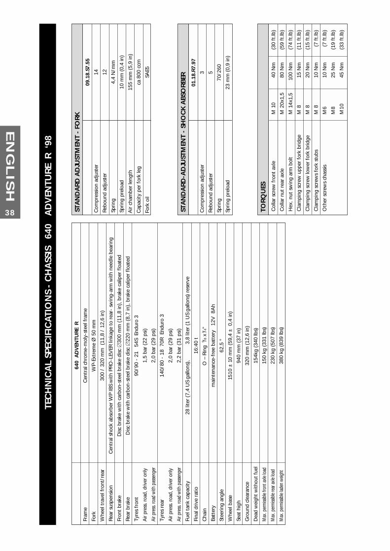
EN
GLIS
H
38
TEC
HN
ICA
L SP
ECIF
ICA
TIO
NS
- C
HA
SSIS
64
0 A
DV
ENTU
RE
R ‘
98
640
AD
VEN
TUR
E R
Fram
eC
entr
al c
hrom
e-m
oly-
stee
l fra
me
Fork
WP-
Extr
eme
Ø 5
0 m
m
Whe
el t
rave
l fro
nt/r
ear
300
/ 32
0 m
m (
11,8
/ 1
2,6
in)
Rea
r su
spen
sion
Cen
tral
sho
ck a
bsor
ber
WP
IBS
with
PR
O-L
EVER
link
age
to r
ear-
sw
ing-
arm
with
nee
dle
bear
ing
Fron
t br
ake
Dis
c br
ake
with
car
bon-
stee
l bra
ke d
isc
�30
0 m
m (
11,8
in),
bra
ke c
alip
er f
loat
ed
Rea
r br
ake
Dis
c br
ake
with
car
bon-
stee
l bra
ke d
isc
�22
0 m
m (
8,7
in),
bra
ke c
alip
er f
loat
ed
Tyre
s fr
ont
90/9
0 -
21
54S
End
uro
3
Air
pres
s. ro
ad, d
river
onl
y1,
5 ba
r (2
2 ps
i)
Air p
ress
. roa
d w
ith p
asse
nger
2,0
bar
(29
psi)
Tyre
s re
ar14
0/80
- 1
8 7
0R E
ndur
o 3
Air
pres
s. ro
ad, d
river
onl
y2,
0 ba
r (2
9 ps
i)
Air p
ress
. roa
d w
ith p
asse
nger
2,2
bar
(31
psi)
Fuel
tan
k ca
paci
ty28
lite
r (7
,4 U
S ga
llons
),
3,8
lite
r (1
US
gallo
ns)
rese
rve
Fina
l driv
e ra
tio16
:40
t
Cha
inO
– R
ing
5 /8x
1 /4"
Batt
ery
mai
nten
ance
-fre
e ba
tter
y 1
2V 8
Ah
Stee
ring
angl
e62
,5 °
Whe
el b
ase
1510
±10
mm
(59
,4 ±
0,4
in)
Seat
hig
h94
0 m
m (
37 in
)
Gro
und
clea
ranc
e32
0 m
m (
12,6
in)
Dea
d w
eigh
t with
out f
uel
154k
g (3
40 lb
s)
Max
. per
miss
ible f
ront
axle
load
150
kg (
331
lbs)
Max
. per
miss
ible r
ear a
xle lo
ad23
0 kg
(50
7 lb
s)
Max
. per
miss
ible l
aden
weig
ht38
0 kg
(83
9 lb
s)
01.1
8.R
7.97
Com
pres
sion
adj
uste
r3
Reb
ound
adj
uste
r5
Sprin
g70
/260
Sprin
g pr
eloa
d23
mm
(0,
9 in
)
STA
ND
AR
D-A
DJU
STM
ENT
- SH
OC
K A
BSO
RB
ER
09.1
8.S7
.55
Com
pres
sion
adj
uste
r14
Reb
ound
adj
uste
r12
Sprin
g4,
4 N
/mm
Sprin
g pr
eloa
d10
mm
(0,
4 in
)
Air
cham
ber
leng
th15
5 m
m (
5,9
in)
Cap
acity
per
for
k le
gca
800
ccm
Fork
oil
SAE5
STA
ND
AR
D A
DJU
STM
ENT
- FO
RK
Col
lar
scre
w f
ront
axl
eM
10
40 N
m(3
0 ft
.lb)
Col
lar
nut
rear
axl
eM
20x
1,5
80 N
m(5
9 ft
.lb)
Hex
. nut
sw
ing
arm
bol
tM
14x
1,5
100
Nm
(74
ft.lb
)
Cla
mpi
ng s
crew
upp
er f
ork
brid
geM
815
Nm
(11
ft.lb
)
Cla
mpi
ng s
crew
low
er f
ork
brid
geM
820
Nm
(15
ft.lb
)
Cla
mpi
ng s
crew
s fo
rk s
tubs
M 8
10 N
m
(7 f
t.lb
)
Oth
er s
crew
s ch
assi
sM
610
Nm
(7 f
t.lb
)
M8
25 N
m(1
9 ft
.lb)
M10
45 N
m(3
3 ft
.lb)
TOR
QU
ES

K T M - S P O R T M O T O R C Y C L E A GA - 5 2 3 0 M a t t i g h o f e n • P o s t f a c h 9 1 • A u s t r i aI n t e r n e t : h t t p : / / w w w . k t m . c o . a tFN 102019 d - L andesge r i ch t R i ed im I nnk r e i s