beetlebot - solarbotics · beetlebot ... the project has since has been turned into popular...
TRANSCRIPT

BeetleBotBeetleBotBeetleBot
www.solarbotics.com1-866-276-2687
Based on the popular MAKE Magazine and Instructables.com project, the BeetleBot is
the simplest TRUE robot you can build. Assembles with just a screwdriver (included)!
Document Revision: July 4th, 2011SKU: K JB
The Simple Zippy Screw-Together Robot Kit!
http://www.solarbotics.com/products/k_ jb/

Parts:1 x Acrylic BeetleBot baseplate1 x Acrylic BeetleBot top shell1 x Acrylic Switch Spacer1 x Switch Harness1 x Power Switch Harness2 x Wire Antennae2 x Antenna switches2 x Aluminium motor brackets2 x Motors with hubs2 x Rubber Tires1 x Double-Sided Sticky-Tape1 x Tail Caster
2 x 2AAA Battery Packs16 x 2-56 x 1/4” long screws4 x 2-32 x 3/8” long screws3 x 2-56 x 5/8” long screws3 x 5/8” nylon spacers6 x 10cm (4”) Black Legs Wires1 x Sticker sheet1 x Solarbotics Screwdriver
Parts and Tools needed, but not included:4 - AAA 1.5V BatteriesScissors
We strongly suggest you inventory the parts in your kit to make sure you have all the parts listed. If anything is missing, contact Solarbotics Ltd. for replacement parts information.“SOLARBOTICS” is a trademark of Solarbotics Ltd. Reg. CIPO / USPTO.
Disclaimer of LiabilitySolarbotics Ltd. is not responsible for any special, incidental, or consequential damages resulting from any breach of warranty, or under any legal theory, including lost profits, downtime, good-will, damage to or replacement of equipment or property, and any costs or recovering of any material or goods associated with the assembly or use of this product. Solarbotics Ltd. reserves the right to make substitutions and changes to this product without prior notice. Yeah, we hate legalese too.
2 xSwitches
Main Board
2 x Rubber Tires
2 x MotorsTail Caster
2 x 2AAABattery Packs
2
2 x SensorWires
6 xLeg wires
3 x2-56 x 5/8”screws
Shell Board
Switch Spacer
Decal Sheet
2 x Motor Mounts
3 xNylon Spacers
16 x 2 - 56 x 1/4”screws
SwitchHarness
Power SwitchHarness
Screwdriver
1 xDouble-sidedSticky Tape
4 x2-32 x 3/8” screws

3
The BeetleBot:The BeetleBot started as Jérôme Demers' high-school science fair project. He built an extremely simple and effective circuit using just a pair of cleverly wired switches, two batteries, and two motors.
This robot would zoom around an enclosure, cleverly bouncing off all obstacles using its antenna-like bump sensors. Jérôme's goal behind this project was to demonstrate how you can achieve a complex robot behavior with minimal design and simple parts.
The BeetleBot earned Jérôme several awards, and a trip to the 2001 International Science Fair. The project has since has been turned into popular do-it-yourself articles published by Instructables.com and Makezine.com.
As an intern at Solarbotics, Jérôme turned his creation into the BeetleBot Solderless Kit. This kit features the same clever design as the original, but assembles with plug-in connectors and simple screw and plastic construction.
The robot is built on a laser-cut acrylic base prepared for all screws and component layouts. Pre-assembled wire harnesses plug into the switches, batteries, and motors. The included wire antennae are pre-formed to give the robot an insect-like appearance and provide efficient obstacle detection.
Spend an hour or so to put it together, then customize it with a selection of stickers!
The BeetleBot is available in two shapes, Ladybug or Tribal, each in four colours.
If you want to try building your own BeetleBot from scratch, find construction articles online at http://www.instructables.com/id/How-to-Build-a-Robot---The-BeetleBot/ and at http://www.make-digital.com/make/vol12/?folio=140#pg150

Screwdriver - The Essentials:Just in case if you haven’t used a screwdriver, here’s some tips:
4
Step 1: Place it in your palm like... um... a screwdriver. And then admire the beautiful Solarbotics-branded screwdriver that came with your kit.
Step 3: DO NOT hold it like this. It will be harder to “aim” your screwdriver. This grip is reserved only for repelling shark attacks.
Step 2: Use a comfortable grip that supports the end of the screwdriver handle in your palm. Feel free to remove the metal shirt-clippy thing so it feels better in your hand.
“Righty-Tighty, Lefty-Loosey”. To install screws, rotate the screwdriver clockwise. “Turning it to the right” means that if the screwdriver was laying on the table, turning it to the right make the screwdriver roll to the right. That’s the way Dad taught it to me.
Screwdriver tip:If you find it hard to screw the screws into the baseplate, back the screw out a bit, then screw it back in some more.

Top/Bottom
Step 1 - Preparing the laser cut baseplate:Let’s start by making sure our baseplate is ready to go. Being laser-cut, there might be some small pieces that didn’t fully clear out, so take a close look at each hole to make sure they are clear. If not, use your thumb to nudge the bits out.
When you are sure all the holes are cleared out, peel off the protective paper mask. The little black bits can be thrown out.
Step 1a: Press out any bit that might be stuck... Step 1b: ...then peel off the protective paper.
We’ll show you what your project should look like at the end of each step. Not much here, but the baseplate with nice, clean holes!
5
(there’s no difference between top & bottom at the moment)

TOP BOTTOM
Step 2 - Installing the Antennae:The antennae work with the switches to create the “brains” of your Beetlebot. Get your antennae, and two of the 2-56 x 1/4” screws.
Just so you know, “2” refers to the diameter size of bolt, “56” is the number of grooves (per inch), and the 1/4” is how long it is.
Pick a side of the baseplate to call “the top”. Screw one antenna down to the hole shown in the picture below until the screw stops going in. Then back it out 1/4 of a turn so the antenna swivels loosely, but won’t pop the “S” curve out of the slot.
Add the other antenna to the other side. When you are done, you should have two floppy antennae mounted to your baseplate!
This is the screw you need (full-size shown here)
X 2
6

TOP BOTTOM
Step 3 - Switch Installation:Let’s nest the switch in behind the antenna and screw it in. Make sure the tab points forward, and put screws in from the other side (the bottom) this time.
3c: Hold the switch on the screws, and finish screwing both screws in.
Make sure the switch tabpoints forward!
Note tab points
forward!
Make sure the screws are going in properly, or else you will break the switch!
7
Switch detail
3b: TOP VIEW. See how the screws are
just poking out through the top, now place the switch into position with the metal tab touching the antenna wire.
3a: BOTTOM VIEW. Place in two of the 2-32 x 3/8” long screws into the baseplate (from the bottom).
TOP BOTTOM
8
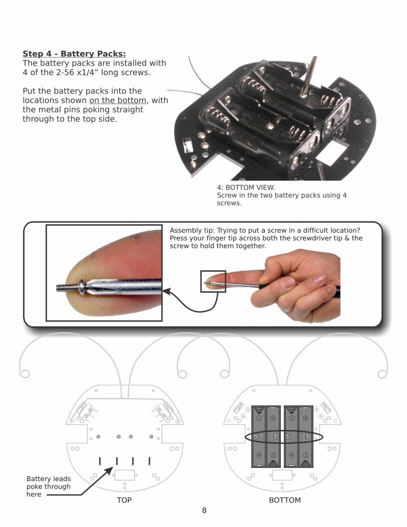
4: BOTTOM VIEW. Screw in the two battery packs using 4 screws.
Step 4 - Battery Packs:The battery packs are installed with 4 of the 2-56 x1/4” long screws.
Put the battery packs into the locations shown on the bottom, with the metal pins poking straight through to the top side.
Battery leadspoke throughhere
Assembly tip: Trying to put a screw in a difficult location? Press your finger tip across both the screwdriver tip & the screw to hold them together.

TOP BOTTOM
9
Step 5 - The Motor Mounts:The motor mounts are installed from the TOP SIDE of the baseplate. Install the mounts, each with two more of those wonderful 1/4” long screws we’ve been using so far.
Screw on the MotorMounts from the TOP SIDE
(the antennae were removedfrom the photos for a better view - don’t remove them from yours!)

TOP BOTTOM
10
Step 6 - The Motors and Wheels:Your motors come with white nubs on the shaft. Push the rubber wheels over the nubs.
Find your two motors and the “double-sided sticky-tape” (”DSST”). If you want, cut the DSST in half to make it fit the motor better.
Find the WHITE DOT on the back of the motor. You want to put the DSST on the same side of the motor that the dot is. Peel off the DSST protective tape, and stick it to the motor.
Peel off the other piece of protective tape, and stick the motors on the motor mounts as shown below on the picture. Make the back of the motor align with the bend on the motor mount, so when you put it down, the Beetlebot sits on the two wheels and NOT the battery pack.
6a: Push the rubber wheels onto the motor nubs
6b: Find the white dots on the motors, and stick the DSST on the side nearest the dot
Note where white spot is! Make it match!
6c: Before you stick down the motor, find the white spots, and match this photo. Then stick the motors onto the mounts!
WhiteSpots!
TOP

TOP BOTTOM
11
Step 7 - The Power Switch:The switch gets in the way if we mount it directly to the baseplate, so we have to put it on a spacer plate.
Start by threading the 1/4” screws into the front of the switch. It will be a bit tough, but will start twisting easier as you go further in.
Next, slip the wires of the switch through the spacer hole, and adjust the screws so they just poke out the back of the spacer.
Drop the whole works into the rectangle on the BOTTOM of the baseplate, and finish screwing in the screws! Don’t worry if it doesn’t feel like it’s grabbing, as step 8 will help!
7a: All the parts - switch, spacer and 2 screws
7b: Put the screws in (use some force).
7c: Put the switch into the spacer.
7d: Adjust the screws so they just poke out the back of the spacer
7e: Drop the whole works into the BOTTOM of the baseplate, and tighten the screws!

TOP BOTTOM
12
Step 8 - The Tail Spring:Your Beetlebot is quick! The tail spring keeps the Beetlebot from violently rocking back and forth and making the antenna activate by accident.
It’s a simple installation - just take another one of those oh-so-handy 1/4” screws and screw the tail spring to the switch spacer as shown below! This will also help lock down the switch and spacer to the main board.
Make sure to use the REAR hole. The forward hole is saved for mounting the shell later.
Make sure to screwit to the REAR hole!

TOP BOTTOM
13
Step 9 - Plugging in the Main Wire & Switch Harness:With the antenna switches, these wiring harnesses make up the “smarts” of the Beetlebot. Simply plug the wires into the positions shown.
The plugs slide onto the switches easily, but will stay firm. If you are not sure if it is connected right, unplug it and replug it in again. It should “stick” a bit when you try to pull it out.
The rest of the wire plugs fit in nice and smooth, with no “sticking”.Note: If you plug it the harness in backwards, it will run backwards (cool, but wrong!)

Step 10 - Initial Testing:You are now done with the technical assembly of your Beetlebot. Let’s plug batteries in, and see if it works! It should zoom forward until an antenna is pressed, and the motor on the opposite side of that antenna should reverse. Put it on the floor aimed toward the wall. It should turn away from the wall when it hits the wall.
Everything good? Yay! Do a happy dance, and go on with the final stages of assembly.
Is it not working properly? Hrm. Let’s check some things:
Nothing working at all? Make sure the batteries are in the right way around, and that the switch harness is plugged into the batteries.
It’s spinning on the spot? Does it run forward by pressing one of the antenna? If so, then fix the reversed motor by swapping the motor lead connections.
Can’t fix it by activating an antenna? Check if the antenna has slipped over or behind the metal lever on the switch.
Is it spinning around one of the wheels (one wheel isn’t doing anything)? Check if the black wheel isn’t stuck up against the motor itself. Slide it down the white nub so it rolls free again.
Check if the motor wires are connected by unplugging and plugging them back in again.
If none of these steps solved your problem, it’s time to start looking carefully at the solder connections between the motors and wires, and the wire connections to the plugs on the harnesses. If you can, you might have to find a soldering iron to fix problems like this. Or contact us, and we’ll help you figure out the best solution for you!
Contact us for help at [email protected] or toll free 1-866-276-2687
:D
14

TOP BOTTOM
15
Step 11 - Adding the Legs:What’s a Beetle if it doesn’t have legs? Find the 6 pieces of black wire, and follow these steps to add the legs. When installed, bend them in a beetle-like shape that doesn’t rub the floor (which will slow it down).
11a: Insert the end ofthe wire in any leg hole
11b: Bend the wire overso it lays flat
11c: Keep bending thewire over the side
11d: Remove theleg from the hole
11e: Move it over to theother hole, and reinsert
11f: Bend the lower leg up to lock it into place

SO
LA
RB
OTIC
S B
EETLEB
OT S
TIC
KER
SH
EET V
1.0
11
2
33
44
45
5
6
1
11
2
3
44
5
5
SO
LA
RB
OTIC
S B
EETLEB
OT S
TIC
KER
SH
EET V
1.0
77
Step 12 - Stickers!:Stickers are fun - no doubt about it! Find the top plate, and get to work. Here’s a map to where everything goes. Use the cover for ideas. Feel free to make changes and give your Beetlebot a custom look, then we’ll put it all together!
16
1 - Eyes (center dot over screw holes)2 - Left / Right Shells3 - Eye dots (go on top of #1)4 - Mouth (grin or smirk)5 - Decorations6 - Stars (just for fun!)
1 - Eyes / Tatoos 2 - Mouth (grin)3 - Shell4 - Main body 5 - Horns / ridges6 - There is no #67 - Stick these on your nose. Or
someplace. Have fun!

TOP BOTTOM
Step 13 - Final Assembly:Take your decorated shell, and get ready to install it to the baseplate. You will finally use those long three screws and the white nylon spacers (that look like a stubby piece of macaroni).
First, flatten the battery pack pins down and tuck all the wires in towards the middle so they won’t get in the way of the shell
Then put in a long screw through the top shell, and the nylon spacer underneath. Screw the screw into the bottom shell, and repeat it for the other two mounting holes.
Step 13a - Flatten downthe battery pack pins
Step 13b - Put a screw in through the top, and a spacer underneath
Step 13c - Screw it in to the baseplate.
Note how the antennastays behind the screw& spacer
17
Install shell mountingscrews here

How it Works:The key to how the Beetlebot works is in the switches. They are not simple on/off switches - they are “Single Pole / Double Throw” switches, which means they make a connection to one wire or the other wire - there’s no “in between”.
The motors are connected from between the two battery packs to a switch. Depending on the switch, the other wire to the motor is connected to the “+” side of one pack, or the “-” side of the other pack. Since motors change direction when you reverse the power connections, this behavior lets the switch and two battery packs change the direction of the robot.
The power switch has several wires because it disconnects both battery packs. If you disconnect only one wire, your BeetleBot will stop running forwards, but will still run backwards.
-
+
-
+
BeetleBot Simplified Schematic
18
Normal operation: Power goes from Pack-A “-” through motor, and back to Pack-A “+”. This makes the motor spin clockwise.
Antenna switch activated: Power is switched from Pack-A to Pack-B, flowing from Pack-B “+” to Pack-B “-”. Now the motor spins the other way, counter-clockwise. Simple!
Note how switch has moved
Push
Power Switch
Right AntennaSwitch
Left Antenna
Switch
BeetleBot Operational Schematic
+ - +-
Pack-A
Pack-B
Pack-A
Pack-B

Troubleshooting:So you’ve had your BeetleBot for a while, but now it’s not running quite right? Here’s some troubleshooting tips:
“It’s moving in curves all the time!” - The tire has most likely slipped up the hub, and is now rubbing the motor body. Just slide the tire back down again.
“It’s not turning Left/Right!” - The Antenna might have slipped out of the slot in front of the switch, or it slipped behind the metal tab of the switch itself. Just pull it loose so it’s sitting in the slot again.
“It’s sorta barely moving around it a circle” - The motor mount might have been bent if your Beetlebot fell off a counter, or something fell on it. Check to see that the motors are bent down enough that the battery pack is not rubbing on the floor.
“It’s working, but moving kinda slow” - The wheels are rubbing on both motors (see first problem), or you’ve used your Beetlebot so much the batteries are wearing down. Or there’s a bunch of gunk wrapped around the wheel axles.
“It was fine last night, but now it’s all in pieces!” - Check with the dog. Betcha Rover thought it was a “chase-me chew-toy”. Either that, or somebody figured out you can take it apart as easy as you put it together (check with your little brother or sister)!
Rubbing Tire Clear Tire
19
!Have fun with your BeetleBot - look online for other ways of building another one, and keep building. It’s fun!

Based on our HexPummer, this kit charges all day from the SCC3733 solar cell. In the dark it “pumms” the two ultra-mega-super-bright LEDs and casts artistic silhouettes against the walls of the lantern.
K HP-L HexPummer Lantern . . . . . .$33.50USD/CAD
The SolarSpeeder 2 Kit is a very quick Solaroller that can cover 3 meters (10 feet) in under 40 seconds in direct sunlight. Simple to construct and a blast to watch, this is a great kit for all beginners!
K SS Solarspeeder . . . . . . . . . . . . . $27.50USD/CAD
Like the Mousebot, the K PP Photopopper seeks light and avoids obstacles but is solar powered! It’s pretty quick, covering a meter per minute (that’s 3.3 feet!). Newly upgraded with better electronics and gold circuit board!
K PP Photopopper . . . . . . . . . . . . $35.95USD/CAD
Wishing you had a bit more of a vicious light-seeker? Well, try our Turbot! Dubbed the Velociraptor of the Robot Jurassic Park, the K TB Turbot moves by flipping end over end on it’s long legs. It’s capable, but smart enough to let go when it’s taking on too big of a challenge!
K TB Turbot . . . . . . . . . . . . . . . . . .$59.95USD/CAD
Solarbotics Ltd.
3740D - 11A Street NE, Suite 101Calgary, Alberta T2E 6M6
Canada
Toll Free: 1-866-276-2687International: +1 (403) 232-6268
Fax: +1 (403) 226-3741
Made in Canada
Visit us online for more info and cool stuff:
www.solarbotics.com
Enjoyed the BeetleBot? Want more?There are several more kits from Solarbotics for any skill level!