before troubleshooting19-2 0 connector...
TRANSCRIPT

19-1
0123456789101112131415161718192021E
ELECTRICAL SYSTEM TROUBLESHOOTINGPage
BEFORE TROUBLESHOOTING..........................19-2CONNECTOR HANDLING.......................................19-2WIRE HARNESS AND CONNECTOR
INSPECTION PROCEDURE ..................................19-2TROUBLESHOOTING..........................................19-4
BEFORE BEGINNING TROUBLESHOOTING FOR THE 4Y-E ENGINE........................................19-4
DIAGNOSIS (SELF DIAGNOSIS FUNCTION) ............19-5DIAGNOSIS DISPLAY METHOD..............................19-5LIST OF DIAGNOSIS CODES..................................19-6WARNING LIST ...................................................19-12VIEWING RELATED PORTIONS............................19-13ERROR CONFIRMATION DRIVE MODE.................19-13TROUBLESHOOTING BY ERROR CODE...............19-14TROUBLESHOOTING WHEN THERE IS
NO ERROR CODE ...........................................19-156
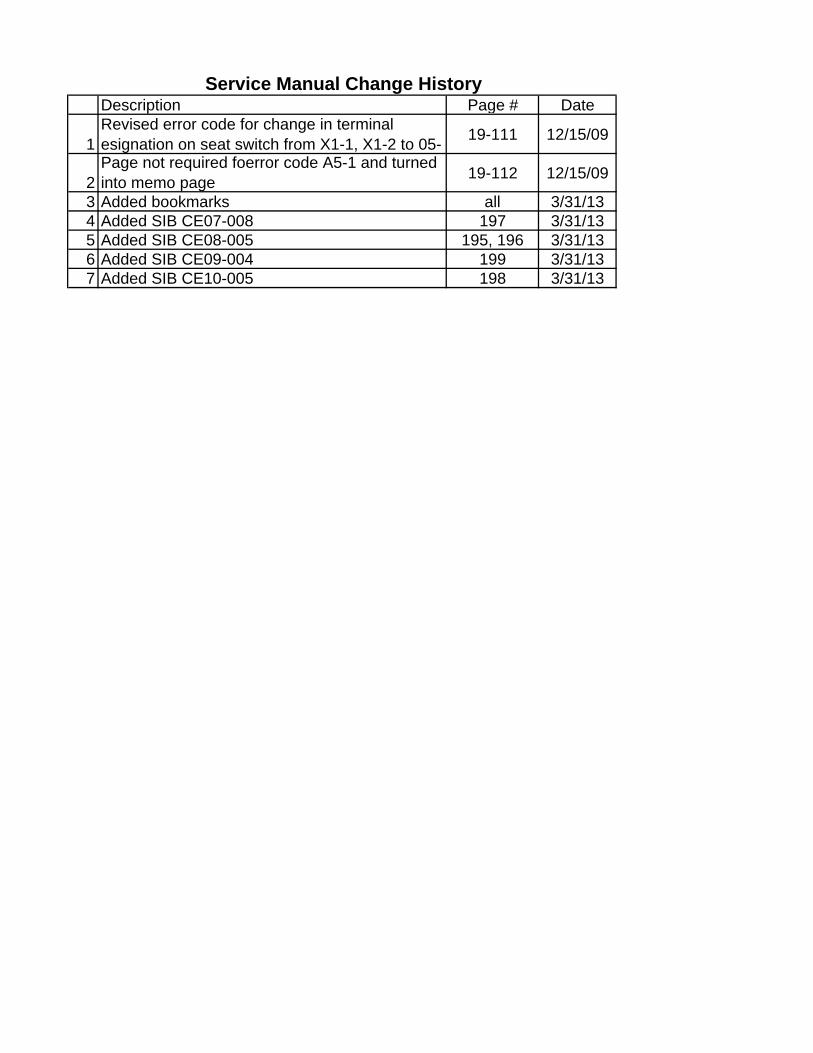
Description Page # Date
1Revised error code for change in terminal esignation on seat switch from X1-1, X1-2 to 05- 19-111 12/15/09
2Page not required foerror code A5-1 and turned into memo page 19-112 12/15/09
3 Added bookmarks all 3/31/134 Added SIB CE07-008 197 3/31/135 Added SIB CE08-005 195, 196 3/31/136 Added SIB CE09-004 199 3/31/137 Added SIB CE10-005 198 3/31/13
Service Manual Change History
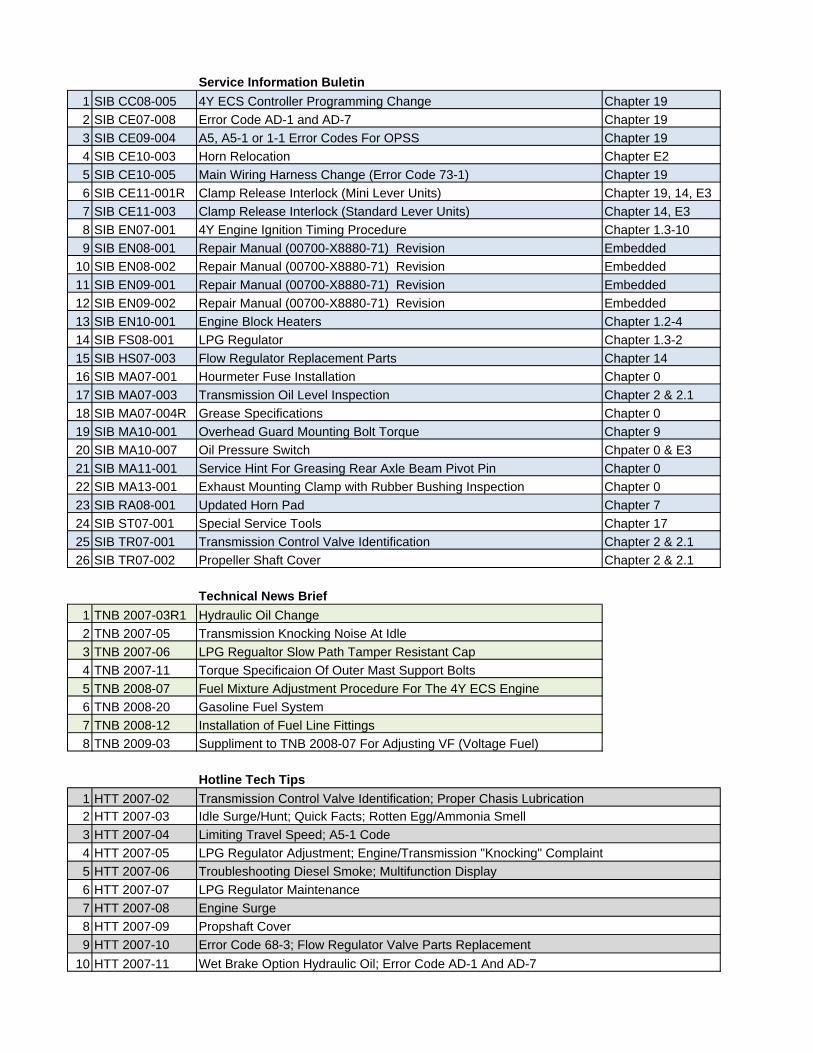
Service Information Buletin1 SIB CC08-005 4Y ECS Controller Programming Change Chapter 192 SIB CE07-008 Error Code AD-1 and AD-7 Chapter 193 SIB CE09-004 A5, A5-1 or 1-1 Error Codes For OPSS Chapter 194 SIB CE10-003 Horn Relocation Chapter E25 SIB CE10-005 Main Wiring Harness Change (Error Code 73-1) Chapter 196 SIB CE11-001R Clamp Release Interlock (Mini Lever Units) Chapter 19, 14, E37 SIB CE11-003 Clamp Release Interlock (Standard Lever Units) Chapter 14, E38 SIB EN07-001 4Y Engine Ignition Timing Procedure Chapter 1.3-109 SIB EN08-001 Repair Manual (00700-X8880-71) Revision Embedded
10 SIB EN08-002 Repair Manual (00700-X8880-71) Revision Embedded11 SIB EN09-001 Repair Manual (00700-X8880-71) Revision Embedded12 SIB EN09-002 Repair Manual (00700-X8880-71) Revision Embedded13 SIB EN10-001 Engine Block Heaters Chapter 1.2-414 SIB FS08-001 LPG Regulator Chapter 1.3-215 SIB HS07-003 Flow Regulator Replacement Parts Chapter 1416 SIB MA07-001 Hourmeter Fuse Installation Chapter 017 SIB MA07-003 Transmission Oil Level Inspection Chapter 2 & 2.118 SIB MA07-004R Grease Specifications Chapter 019 SIB MA10-001 Overhead Guard Mounting Bolt Torque Chapter 920 SIB MA10-007 Oil Pressure Switch Chpater 0 & E321 SIB MA11-001 Service Hint For Greasing Rear Axle Beam Pivot Pin Chapter 022 SIB MA13-001 Exhaust Mounting Clamp with Rubber Bushing Inspection Chapter 023 SIB RA08-001 Updated Horn Pad Chapter 724 SIB ST07-001 Special Service Tools Chapter 1725 SIB TR07-001 Transmission Control Valve Identification Chapter 2 & 2.126 SIB TR07-002 Propeller Shaft Cover Chapter 2 & 2.1
Technical News Brief1 TNB 2007-03R1 Hydraulic Oil Change2 TNB 2007-05 Transmission Knocking Noise At Idle3 TNB 2007-06 LPG Regualtor Slow Path Tamper Resistant Cap4 TNB 2007-11 Torque Specificaion Of Outer Mast Support Bolts5 TNB 2008-07 Fuel Mixture Adjustment Procedure For The 4Y ECS Engine6 TNB 2008-20 Gasoline Fuel System7 TNB 2008-12 Installation of Fuel Line Fittings8 TNB 2009-03 Suppliment to TNB 2008-07 For Adjusting VF (Voltage Fuel)
Hotline Tech Tips1 HTT 2007-022 HTT 2007-033 HTT 2007-044 HTT 2007-055 HTT 2007-066 HTT 2007-077 HTT 2007-088 HTT 2007-099 HTT 2007-10
10 HTT 2007-11
Transmission Control Valve Identification; Proper Chasis LubricationIdle Surge/Hunt; Quick Facts; Rotten Egg/Ammonia SmellLimiting Travel Speed; A5-1 CodeLPG Regulator Adjustment; Engine/Transmission "Knocking" ComplaintTroubleshooting Diesel Smoke; Multifunction DisplayLPG Regulator MaintenanceEngine SurgePropshaft CoverError Code 68-3; Flow Regulator Valve Parts ReplacementWet Brake Option Hydraulic Oil; Error Code AD-1 And AD-7
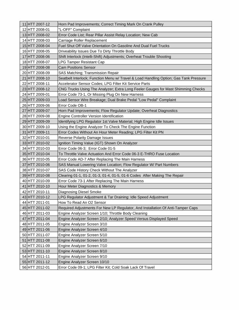
11 HTT 2007-1212 HTT 2008-0113 HTT 2008-0214 HTT 2008-0315 HTT 2008-0416 HTT 2008-0517 HTT 2008-0618 HTT 2008-0719 HTT 2008-0820 HTT 2008-0921 HTT 2008-1022 HTT 2008-1123 HTT 2008-1224 HTT 2009-0125 HTT 2009-0326 HTT 2009-0627 HTT 2009-0728 HTT 2009-0829 HTT 2009-0930 HTT 2009-1031 HTT 2009-1132 HTT 2010-0133 HTT 2010-0234 HTT 2010-0335 HTT 2010-0436 HTT 2010-0537 HTT 2010-0638 HTT 2010-0739 HTT 2010-0840 HTT 2010-0941 HTT 2010-1042 HTT 2010-1143 HTT 2010-1244 HTT 2011-0145 HTT 2011-0246 HTT 2011-0347 HTT 2011-0448 HTT 2011-0549 HTT 2011-0650 HTT 2011-0751 HTT 2011-0852 HTT 2011-0953 HTT 2011-1054 HTT 2011-1155 HTT 2011-1256 HTT 2012-01
Engine Analyzer Screen 10/10Error Code 09-1; LPG Filter Kit; Cold Soak Lack Of Travel
Engine Analyzer Screen 4/10Engine Analyzer Screen 5/10Engine Analyzer Screen 6/10Engine Analyzer Screen 7/10Engine Analyzer Screen 8/10Engine Analyzer Screen 9/10
Engine Analyzer Screen 3/10
SAS Manual Lowering Valve Location; Flow Regulator W/ Part NumbersSAS Code History Check Without The AnalyzerClearing 01-1, 01-2, 01-3, 01-4, 01-5, 01-6 Codes After Making The Repair Error Code 73-1 After Replacing The Main HarnessHour Meter Diagnostics & MemoryDiagnosing Diesel SmokeLPG Regulator Adjustment & Tar Draining: Idle Speed AdjustmentHow To Read An O2 SensorRequired Adjustments For New LP Regulator, And Installation Of Anti-Tamper CapsEngine Analyzer Screen 1/10; Throttle Body CleaningEngine Analyzer Screen 2/10; Analyzer Speed Versus Displayed Speed
Error Code AD-7 After Replacing The Main Harness
Load Sensor Wire Breakage; Dual Brake Pedal "Low Pedal" ComplaintError Code OB-1 Horn Pad Improvements; Flow Regulator Update; Overheat DiagnosticsEngine Controller Version IdentificationIdentifying LPG Regulator 1st Valve Material; High Engine Idle IssuesUsing the Engine Analyzer To Check The Engine FunctionError Codes Without An Hour Meter Reading; LPG Filter Kit PNReverse Polarity Damage IssuesIgnition Timing Value (IGT) Shown On AnalyzerError Code 06-3; Error Code 01-5To Throttle Valve Actuation And Error Code 06-3 E-THRO Fuse Location
Error Code 73-1, Or Missing Plug On New Harness
Error Code List; Rear Pillar Assist Relay Location; New CabCarriage Roller ReplacementFuel Shut Off Valve Orientation On Gasoline And Dual Fuel TrucksDriveability Issues Due To Dirty Throttle BodyShift Interlock (Intelli-Shift) Adjustments; Overheat Trouble ShootingLPG Tamper Resistant CapCam Positions SensorSAS Matching; Transmission RepairSeatbelt Interlock; Function Menu w/ Travel & Load Handling Option; Gas Tank PressureAccelerator Sensor Codes; LPG Filter Kit Service PartsCNG Trucks Using The Analyzer; Extra Long Feeler Gauges for Mast Shimming Checks
"L-OFF" ComplaintHorn Pad Improvements; Correct Timing Mark On Crank Pulley

19-219-2
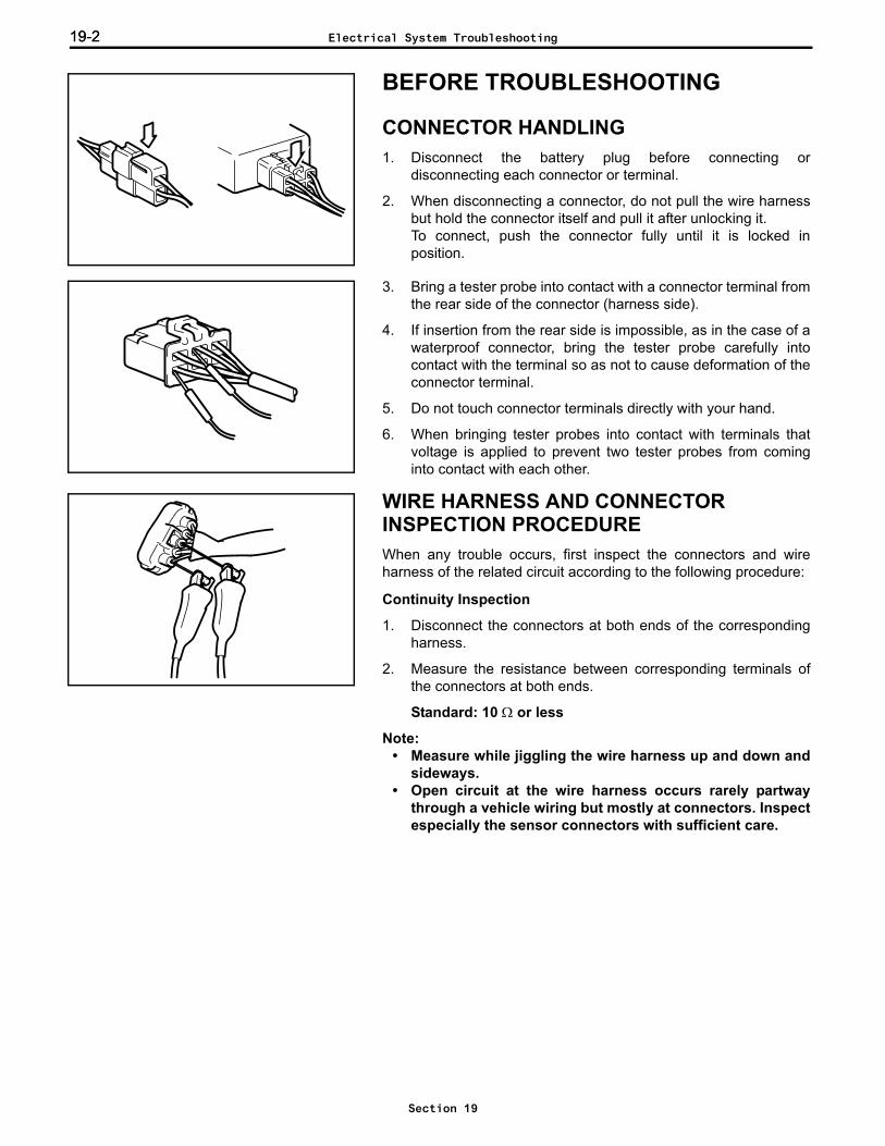
BEFORE TROUBLESHOOTING
CONNECTOR HANDLING1. Disconnect the battery plug before connecting or
disconnecting each connector or terminal.
2. When disconnecting a connector, do not pull the wire harnessbut hold the connector itself and pull it after unlocking it.To connect, push the connector fully until it is locked inposition.
3. Bring a tester probe into contact with a connector terminal fromthe rear side of the connector (harness side).
4. If insertion from the rear side is impossible, as in the case of awaterproof connector, bring the tester probe carefully intocontact with the terminal so as not to cause deformation of theconnector terminal.
5. Do not touch connector terminals directly with your hand.
6. When bringing tester probes into contact with terminals thatvoltage is applied to prevent two tester probes from cominginto contact with each other.
WIRE HARNESS AND CONNECTOR INSPECTION PROCEDUREWhen any trouble occurs, first inspect the connectors and wireharness of the related circuit according to the following procedure:
Continuity Inspection
1. Disconnect the connectors at both ends of the correspondingharness.
2. Measure the resistance between corresponding terminals ofthe connectors at both ends.
Standard: 10 Ω or less
Note:• Measure while jiggling the wire harness up and down and
sideways.• Open circuit at the wire harness occurs rarely partway
through a vehicle wiring but mostly at connectors. Inspectespecially the sensor connectors with sufficient care.
Electrical System Troubleshooting
Section 19

19-3
0123456789101112131415161718192021E
Short Circuit Check1. Disconnect the connectors at both ends of the corresponding
harness.
2. Measure the resistance between the corresponding connectorterminal and frame. Be sure to inspect the connectors at bothends.
Standard: 1 MΩ or above
Note:Measure while jiggling the wire harness up and down andsideways.
3. Measure the resistance between terminals of thecorresponding connector. Be sure to inspect the connectors atboth ends.
Standard: 1 MΩ or above
Note:The wiring may short-circuit due to pinching by the body ordefective clamping.
Visual and Contact Pressure Checks1. Disconnect the connectors at both ends of the corresponding
harness.
2. Visually inspect that there is neither rust nor foreign mattertrapped at connector terminals.
3. Inspect that there is no looseness or damage at the crimpedportion. Also, lightly pull the wire harness from the connector tocheck that it does not come off.
4. Insert a male terminal same as that of the connector terminalto a female connector and check the drawing force.Defective contact may exist at a terminal where the drawingforce is less than that of other terminals.
Note:Even if there is rust or foreign matter trapped at the terminal,or the contact pressure between male and female terminals islow, abnormal contact condition may be changed to normal bydisconnecting and reconnecting the connector. In this case,disconnect and reconnect the connector several times, and ifa fault occurs even once, then consider the terminal may havea defective contact.
Electrical System Troubleshooting
Section 19
19-419-4
TROUBLESHOOTING
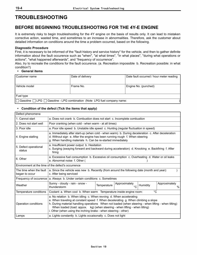
BEFORE BEGINNING TROUBLESHOOTING FOR THE 4Y-E ENGINEIt is extremely risky to begin troubleshooting for the 4Y engine on the basis of results only. It can lead to mistakencorrective action, wasted time, and sometimes to an increase in abnormalities. Therefore, ask the customer aboutdetailed information on conditions around the time a problem occurred, based on the following.
Diagnostic ProcedureFirst, it is necessary to be informed of the "fault history and service history" for the vehicle, and then to gather definiteinformation about the fault occurence such as "when", "at what times", "in what places", "during what operations oractions", "what happened afterwards", and “frequency of occurrence”.Also, try to recreate the conditions for the fault occurence. (a. Recreation impossible b. Recreation possible: in whatcondition?)
• General items
• Condition of the defect (Tick the items that apply)
Customer name Date of delivery Date fault occurred / hour meter reading
Vehicle model Frame No. Engine No. (punched)
Fuel type
Gasoline LPG Gasoline - LPG combination (Note LPG fuel company name: )
Defect phenomena
1. Cannot start a. Does not crank b. Combustion does not start c. Incomplete combustion
2. Does not start well Poor cranking (when cold - when warm - at all times)
3. Poor idle a. Poor idle speed b. Unstable idle speed c. Hunting (regular fluctuation in speed)
4. Engine stallinga. Immediately after start-up (when cold - when warm) b. During deceleration c. After decelerationd. Without sign e. After the engine has been running rough f. When steering g. When handling materials h. Can be re-started immediately
5. Defect operational status
a. Insufficient power output b. Hesitation c. Surging (swaying forward and backward during acceleration) d. Knocking e. Backfiring f. After firing
6. Other a. Excessive fuel consumption b. Excessive oil consumption c. Overheating d. Water or oil leakse. Abnormal noise f. Other ( )
Environment at the time of the defect's occurrence
The time when the fault began to occur
a. Since the vehicle was new b. Recently (from around the following date (month and year): ) c. After being serviced
Frequency of occurence a. Always b. Under certain conditions c. Sometimes
Weather Sunny - cloudy - rain - snow - thunderstorm Temperature Approximately
°C Humidity Approximately%
Temperature conditions Coolant: a. When cool b. When warm Temperature inside engine room: °C
Operation conditions
a. No relation b. When idling c. When revving d. When acceleratinge. When traveling at constant speed f. When decelerating g. When climbing a slopeh. During material handling operations When not loaded (when steering - when lifting - when tilting) When loaded (load: appox. kg) (when steering - when lifting - when tilting)i. Other (when using the inching brake - when steering - other)
Lamps a. Lights constantly b. Lights occaisonally c. Does not light
Electrical System Troubleshooting
Section 19
19-5
0123456789101112131415161718192021E
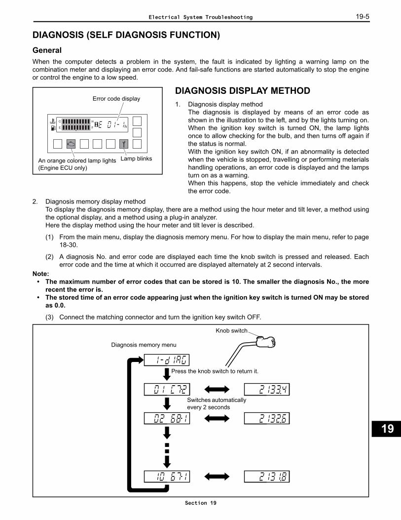
DIAGNOSIS (SELF DIAGNOSIS FUNCTION)GeneralWhen the computer detects a problem in the system, the fault is indicated by lighting a warning lamp on thecombination meter and displaying an error code. And fail-safe functions are started automatically to stop the engineor control the engine to a low speed.
DIAGNOSIS DISPLAY METHOD1. Diagnosis display method
The diagnosis is displayed by means of an error code asshown in the illustration to the left, and by the lights turning on.When the ignition key switch is turned ON, the lamp lightsonce to allow checking for the bulb, and then turns off again ifthe status is normal.With the ignition key switch ON, if an abnormality is detectedwhen the vehicle is stopped, travelling or performing meterialshandling operations, an error code is displayed and the lampsturn on as a warning. When this happens, stop the vehicle immediately and checkthe error code.
2. Diagnosis memory display methodTo display the diagnosis memory display, there are a method using the hour meter and tilt lever, a method usingthe optional display, and a method using a plug-in analyzer. Here the display method using the hour meter and tilt lever is described.
(1) From the main menu, display the diagnosis memory menu. For how to display the main menu, refer to page18-30.
(2) A diagnosis No. and error code are displayed each time the knob switch is pressed and released. Eacherror code and the time at which it occurred are displayed alternately at 2 second intervals.
Note:• The maximum number of error codes that can be stored is 10. The smaller the diagnosis No., the more
recent the error is. • The stored time of an error code appearing just when the ignition key switch is turned ON may be stored
as 0.0.
(3) Connect the matching connector and turn the ignition key switch OFF.
Error code display
An orange colored lamp lights(Engine ECU only)
Lamp blinks
Knob switch
Diagnosis memory menu
Press the knob switch to return it.
Switches automatically every 2 seconds
Electrical System Troubleshooting
Section 19
19-6
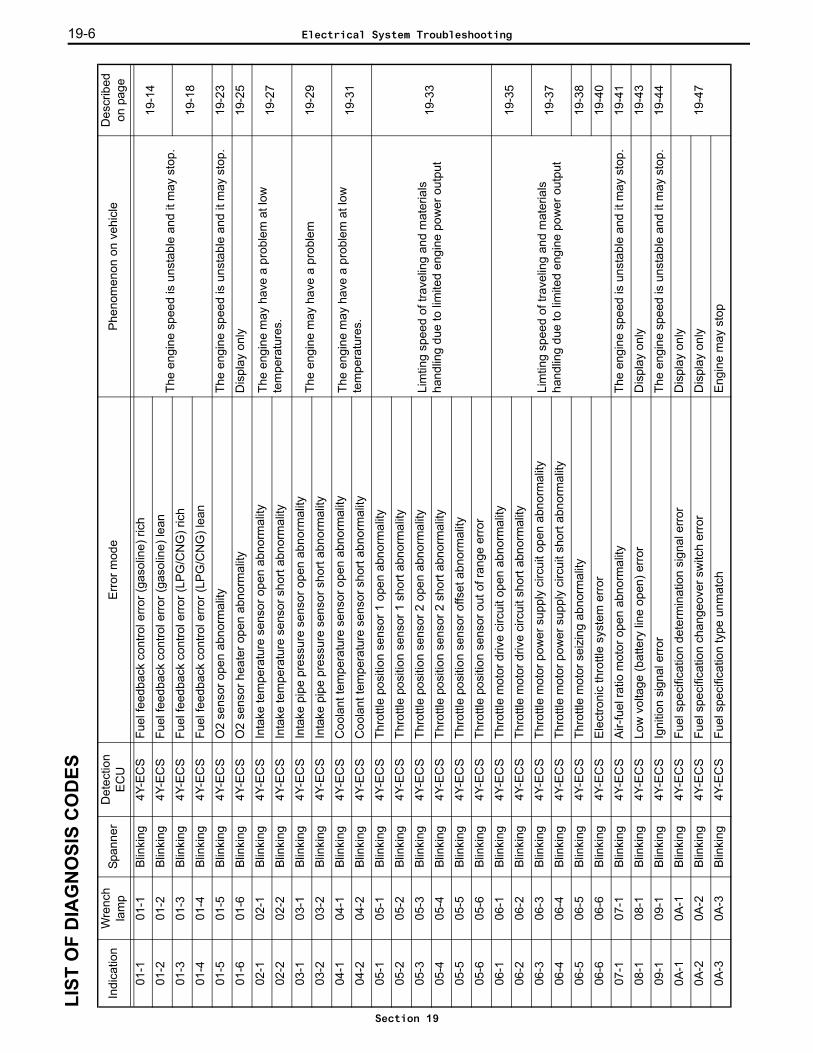
LIST
OF
DIA
GN
OSI
S C
OD
ES
Indi
catio
nW
renc
h la
mp
Span
ner
Det
ectio
n E
CU
Erro
r mod
ePh
enom
enon
on
vehi
cle
Des
crib
ed
on p
age
01-1
01-1
Blin
king
4Y-E
CS
Fuel
feed
back
con
trol e
rror (
gaso
line)
rich
The
engi
ne s
peed
is u
nsta
ble
and
it m
ay s
top.
19-1
401
-201
-2Bl
inki
ng4Y
-EC
SFu
el fe
edba
ck c
ontro
l erro
r (ga
solin
e) le
an
01-3
01-3
Blin
king
4Y-E
CS
Fuel
feed
back
con
trol e
rror (
LPG
/CN
G) r
ich
19-1
801
-401
-4B
linki
ng4Y
-EC
SFu
el fe
edba
ck c
ontro
l erro
r (LP
G/C
NG
) lea
n
01-5
01-5
Blin
king
4Y-E
CS
O2
sens
or o
pen
abno
rmal
ityTh
e en
gine
spe
ed is
uns
tabl
e an
d it
may
sto
p.19
-23
01-6
01-6
Blin
king
4Y-E
CS
O2
sens
or h
eate
r ope
n ab
norm
ality
Dis
play
onl
y19
-25
02-1
02-1
Blin
king
4Y-E
CS
Inta
ke te
mpe
ratu
re s
enso
r ope
n ab
norm
ality
The
engi
ne m
ay h
ave
a pr
oble
m a
t low
te
mpe
ratu
res.
19
-27
02-2
02-2
Blin
king
4Y-E
CS
Inta
ke te
mpe
ratu
re s
enso
r sho
rt ab
norm
ality
03-1
03-1
Blin
king
4Y-E
CS
Inta
ke p
ipe
pres
sure
sen
sor o
pen
abno
rmal
ityTh
e en
gine
may
hav
e a
prob
lem
19-2
903
-203
-2B
linki
ng4Y
-EC
SIn
take
pip
e pr
essu
re s
enso
r sho
rt ab
norm
ality
04-1
04-1
Blin
king
4Y-E
CS
Coo
lant
tem
pera
ture
sen
sor o
pen
abno
rmal
ityTh
e en
gine
may
hav
e a
prob
lem
at l
ow
tem
pera
ture
s.19
-31
04-2
04-2
Blin
king
4Y-E
CS
Coo
lant
tem
pera
ture
sen
sor s
hort
abno
rmal
ity
05-1
05-1
Blin
king
4Y-E
CS
Thro
ttle
posi
tion
sens
or 1
ope
n ab
norm
ality
Lim
ting
spee
d of
trav
elin
g an
d m
ater
ials
ha
ndlin
g du
e to
lim
ited
engi
ne p
ower
out
put
19-3
3
05-2
05-2
Blin
king
4Y-E
CS
Thro
ttle
posi
tion
sens
or 1
sho
rt ab
norm
ality
05-3
05-3
Blin
king
4Y-E
CS
Thro
ttle
posi
tion
sens
or 2
ope
n ab
norm
ality
05-4
05-4
Blin
king
4Y-E
CS
Thro
ttle
posi
tion
sens
or 2
sho
rt ab
norm
ality
05-5
05-5
Blin
king
4Y-E
CS
Thro
ttle
posi
tion
sens
or o
ffset
abn
orm
ality
05-6
05-6
Blin
king
4Y-E
CS
Thro
ttle
posi
tion
sens
or o
ut o
f ran
ge e
rror
06-1
06-1
Blin
king
4Y-E
CS
Thro
ttle
mot
or d
rive
circ
uit o
pen
abno
rmal
ity
Lim
ting
spee
d of
trav
elin
g an
d m
ater
ials
ha
ndlin
g du
e to
lim
ited
engi
ne p
ower
out
put
19-3
506
-206
-2B
linki
ng4Y
-EC
STh
rottl
e m
otor
driv
e ci
rcui
t sho
rt ab
norm
ality
06-3
06-3
Blin
king
4Y-E
CS
Thro
ttle
mot
or p
ower
sup
ply
circ
uit o
pen
abno
rmal
ity19
-37
06-4
06-4
Blin
king
4Y-E
CS
Thro
ttle
mot
or p
ower
sup
ply
circ
uit s
hort
abno
rmal
ity
06-5
06-5
Blin
king
4Y-E
CS
Thro
ttle
mot
or s
eizi
ng a
bnor
mal
ity19
-38
06-6
06-6
Blin
king
4Y-E
CS
Ele
ctro
nic
thro
ttle
syst
em e
rror
19-4
0
07-1
07-1
Blin
king
4Y-E
CS
Air-f
uel r
atio
mot
or o
pen
abno
rmal
ityTh
e en
gine
spe
ed is
uns
tabl
e an
d it
may
sto
p.19
-41
08-1
08-1
Blin
king
4Y-E
CS
Low
vol
tage
(bat
tery
line
ope
n) e
rror
Dis
play
onl
y19
-43
09-1
09-1
Blin
king
4Y-E
CS
Igni
tion
sign
al e
rror
The
engi
ne s
peed
is u
nsta
ble
and
it m
ay s
top.
19-4
4
0A-1
0A-1
Blin
king
4Y-E
CS
Fuel
spe
cific
atio
n de
term
inat
ion
sign
al e
rror
Dis
play
onl
y
19-4
70A
-20A
-2Bl
inki
ng4Y
-EC
SFu
el s
peci
ficat
ion
chan
geov
er s
witc
h er
ror
Dis
play
onl
y
0A-3
0A-3
Blin
king
4Y-E
CS
Fuel
spe
cific
atio
n ty
pe u
nmat
chEn
gine
may
sto
p
Electrical System Troubleshooting
Section 19
19-7
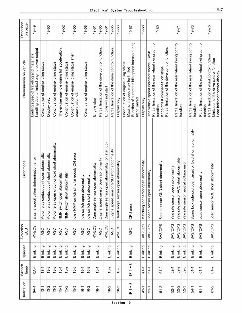
0A-4
0A-4
Blin
king
4Y-E
CS
Engi
ne s
peci
ficat
ion
dete
rmin
atio
n er
ror
Lim
ting
spee
d of
trav
elin
g an
d m
ater
ials
ha
ndlin
g du
e to
lim
ited
engi
ne p
ower
out
put
19-4
9
13-1
13-1
Blin
king
AS
CM
otor
rela
y co
ntac
t poi
nt o
pen
abno
rmal
ityC
ontin
uatio
n of
eng
ine
idlin
g st
atus
19-5
013
-213
-2B
linki
ngA
SC
Mot
or re
lay
cont
act p
oint
sho
rt ab
norm
ality
Dis
play
onl
y
13-3
13-3
Blin
king
AS
CM
otor
rela
y op
en c
ircui
t or l
oad
shor
t abn
orm
ality
Con
tinua
tion
of e
ngin
e id
ling
stat
us
15-1
15-1
Blin
king
ASC
NM
R s
witc
h op
en a
bnor
mal
ityTh
e en
gine
may
idle
dur
ing
full
acce
lera
tion.
19-5
215
-215
-2B
linki
ngA
SC
NM
R s
witc
h sh
ort a
bnor
mal
ityC
ontin
uatio
n of
eng
ine
idlin
g st
atus
15-3
15-3
Blin
king
AS
CId
le /
NM
R s
witc
h si
mul
tane
ousl
y O
N e
rror
Con
tinua
tion
of e
ngin
e id
ling
stat
us a
fter
acce
lera
tion
off.
19-5
5
16-1
16-1
Blin
king
AS
CId
le s
witc
h op
en a
bnor
mal
ityC
ontin
uatio
n of
eng
ine
idlin
g st
atus
19-5
816
-216
-2B
linki
ngA
SC
Idle
sw
itch
shor
t abn
orm
ality
18-1
18-1
Blin
king
4Y-E
CS
Cam
ang
le s
enso
r ope
n ab
norm
ality
Engi
ne s
top
19-6
1
ASC
Engi
ne s
peed
sen
sor o
pen
abno
rmal
ityP
artia
l lim
itatio
n of
the
driv
e co
ntro
l fun
ctio
n.19
-65
18-2
18-2
Blin
king
4Y-E
CS
Cam
ang
le s
enso
r ope
n ab
norm
ality
(on
star
t up)
Engi
ne w
ill no
t sta
rt19
-61
ASC
Engi
ne s
peed
sen
sor G
ND
sho
rt ab
norm
ality
Parti
al li
mita
tion
of th
e dr
ive
cont
rol f
unct
ion.
19-6
5
18-3
18-3
Blin
king
4Y-E
CS
Cra
nk a
ngle
sen
sor o
pen
abno
rmal
ityD
ispl
ay o
nly
19-6
3
1F-1
~ 8
1F-1
~ 8
Blin
king
ASC
CPU
erro
r
Con
tinua
tion
of e
ngin
e id
ling
stat
usM
axim
um s
peed
may
be
limite
dFu
nctio
n of
aut
omat
ic id
le s
peed
incr
ese
durin
g lif
ting
limite
d
19-6
7
41-1
41-1
Blin
king
SA
S/O
PS
Mat
chin
g co
nnec
tor o
pen
abno
rmal
ityD
ispl
ay o
nly
19-6
8
51-1
51-1
Blin
king
SA
S/O
PS
Spee
d se
nsor
ope
n ab
norm
ality
The
vehi
cle
spee
d in
dica
tor s
how
s 0
km/h
Parti
al li
mita
tion
of th
e re
ar w
heel
sw
ing
cont
rol
func
tion.
Kno
b of
fest
com
pens
atio
n st
ops
Parti
al li
mita
tion
of th
e dr
ive
cont
rol f
unct
ion.
19-6
951
-251
-2B
linki
ngS
AS
/OP
SSp
eed
sens
or G
ND
sho
rt ab
norm
ality
52-1
52-1
Blin
king
SA
S/O
PS
Yaw
rate
sen
sor o
pen
abno
rmal
ity
Parti
al li
mita
tion
of th
e re
ar w
heel
sw
ing
cont
rol
func
tion
19-7
152
-252
-2B
linki
ngS
AS
/OP
SYa
w ra
te s
enso
r VC
C s
hort
abno
rmal
ity
52-3
52-3
Blin
king
SA
S/O
PS
Yaw
rate
sen
sor n
eutra
l vol
tage
erro
r
54-1
54-1
Blin
king
SAS/
OPS
Sw
ing
lock
sol
enoi
d op
en c
ircui
t or l
oad
shor
t abn
orm
ality
Parti
al li
mita
tion
of th
e re
ar w
heel
sw
ing
cont
rol
func
tion
19-7
3
61-1
61-1
Blin
king
SA
S/O
PS
Load
sen
sor o
pen
abno
rmal
ityP
artia
l lim
itatio
n of
the
rear
whe
el s
win
g co
ntro
l fu
nctio
nPa
rtial
lim
itatio
n of
mas
t con
trol f
unct
ion
Lim
itatio
n of
the
driv
e co
ntro
l fun
ctio
nLo
ad in
dica
tor c
anno
t dis
play
19-7
561
-261
-2B
linki
ngS
AS
/OP
SLo
ad s
enso
r VC
C s
hort
abno
rmal
ity
Indi
catio
nW
renc
h la
mp
Span
ner
Det
ectio
n E
CU
Erro
r mod
ePh
enom
enon
on
vehi
cle
Des
crib
ed
on p
age
Electrical System Troubleshooting
Section 19

19-8
62-1
62-1
Blin
king
SAS/
OPS
Tilt
angl
e se
nsor
ope
n ab
norm
ality
Parti
al li
mita
tion
of m
ast c
ontro
l fun
ctio
n19
-78
62-2
62-2
Blin
king
SA
S/O
PS
Tilt
angl
e se
nsor
VC
C s
hort
abno
rmal
ity
63-1
63-1
Blin
king
SA
S/O
PS
Tilt
switc
hes
sim
ulta
neou
sly
ON
Parti
al li
mita
tion
of m
ast c
ontro
l fun
ctio
n 19
-81
63-2
63-2
Blin
king
SA
S/O
PS
Tilt
switc
h fo
rwar
d til
t SW
sho
rt
63-3
63-3
Blin
king
SA
S/O
PS
Tilt
switc
h ba
ckw
ard
tilt S
W s
hort
64-1
64-1
Blin
king
SA
S/O
PS
Lift
low
er lo
ck s
olen
oid
open
circ
uit o
r loa
d sh
ort a
bnor
mal
ityLi
ft lo
wer
may
sto
p19
-84
65-1
65-1
Blin
king
SAS/
OPS
Tilt
cont
rol s
olen
oid
open
circ
uit o
r loa
d sh
ort a
bnor
mal
ityFo
rwar
d til
t may
sto
p, b
ackw
ard
tilt m
ay g
o fu
lly
back
19-8
6
66-1
66-1
Blin
king
SAS/
OPS
Out
side
mat
chin
g va
lue
rang
e fo
r tilt
ang
le e
rror
Par
tial l
imita
tion
of m
ast c
ontro
l fun
ctio
n19
-88
67-1
67-1
Blin
king
SA
S/O
PS
Lifti
ng h
eigh
t sw
itch
open
abn
orm
ality
Parti
al li
mita
tion
of th
e re
ar w
heel
sw
ing
cont
rol
func
tion
Parti
al li
mita
tion
of m
ast c
ontro
l fun
ctio
nLi
mita
tion
of th
e dr
ive
cont
rol f
unct
ion
Load
indi
cato
r dis
play
is u
nste
ady
19-8
9
68-1
68-1
Blin
king
SA
S/O
PS
Lift
switc
h ra
ise
and
low
er s
imul
tane
ousl
y O
N e
rror
Low
erin
g m
ay s
top
Func
tion
of a
utom
atic
idle
spe
ed in
cres
e du
ring
liftin
g lim
ited
19-9
268
-268
-2B
linki
ngS
AS
/OP
SLi
ft sw
itch
rais
e S
W s
hort
abno
rmal
ityFu
nctio
n of
aut
omat
ic id
le s
peed
incr
ese
durin
g lif
ting
limite
d
68-3
68-3
Blin
king
SA
S/O
PS
Lift
switc
h lo
wer
SW
sho
rt ab
norm
ality
Low
erin
g m
ay s
top
69-1
69-1
Blin
king
SA
S/O
PS
Back
war
d til
t loc
k so
leno
id o
pen
circ
uit o
r loa
d sh
ort
abno
rmal
ityB
ackw
ard
tilt m
ay s
top
19-9
5
71-1
71-1
Blin
king
SA
S/O
PS
Tire
ang
le s
enso
r ope
n ab
norm
ality
Knob
offe
st c
ompe
nsat
ion
stop
s19
-97
71-2
71-2
Blin
king
SA
S/O
PS
Tire
ang
le s
enso
r VC
C s
hort
abno
rmal
ity
72-1
72-1
Blin
king
SA
S/O
PS
Stee
ring-
whe
el a
ngle
sen
sor S
S1
open
abn
orm
ality
Knob
offe
st c
ompe
nsat
ion
stop
s19
-100
72-2
72-2
Blin
king
SA
S/O
PS
Stee
ring-
whe
el a
ngle
sen
sor S
S2
open
abn
orm
ality
72-3
72-3
Blin
king
SA
S/O
PS
Stee
ring-
whe
el a
ngle
sen
sor S
SC
ope
n ab
norm
ality
72-4
72-4
Blin
king
SAS/
OPS
Stee
ring-
whe
el a
ngle
sen
sors
SS1
and
SS2
ope
n ab
norm
ality
Indi
catio
nW
renc
h la
mp
Span
ner
Det
ectio
n E
CU
Erro
r mod
ePh
enom
enon
on
vehi
cle
Des
crib
ed
on p
age
Electrical System Troubleshooting
Section 19
19-9
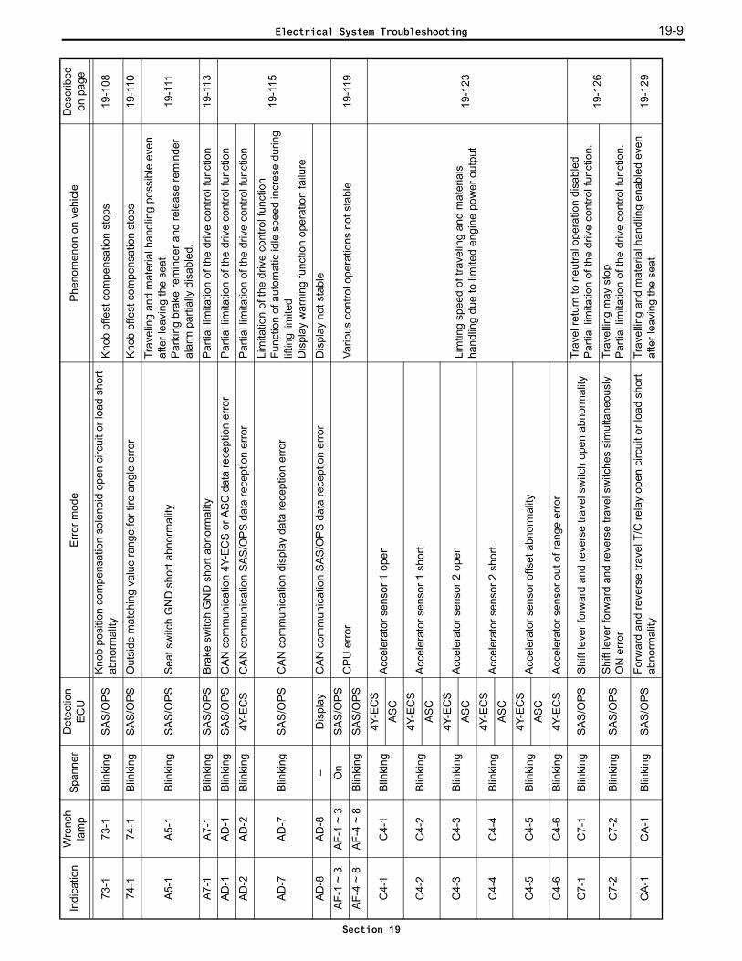
73-1
73-1
Blin
king
SA
S/O
PS
Knob
pos
ition
com
pens
atio
n so
leno
id o
pen
circ
uit o
r loa
d sh
ort
abno
rmal
ityKn
ob o
ffest
com
pens
atio
n st
ops
19-1
08
74-1
74-1
Blin
king
SA
S/O
PS
Out
side
mat
chin
g va
lue
rang
e fo
r tire
ang
le e
rror
Kno
b of
fest
com
pens
atio
n st
ops
19-1
10
A5-
1A
5-1
Blin
king
SA
S/O
PS
Sea
t sw
itch
GN
D s
hort
abno
rmal
ity
Trav
elin
g an
d m
ater
ial h
andl
ing
poss
ible
eve
n af
ter l
eavi
ng th
e se
at.
Park
ing
brak
e re
min
der a
nd re
leas
e re
min
der
alar
m p
artia
lly d
isab
led.
19-1
11
A7-
1A
7-1
Blin
king
SA
S/O
PS
Bra
ke s
witc
h G
ND
sho
rt ab
norm
ality
Par
tial l
imita
tion
of th
e dr
ive
cont
rol f
unct
ion
19-1
13
AD
-1AD
-1B
linki
ngS
AS
/OP
SC
AN
com
mun
icat
ion
4Y-E
CS
or A
SC
dat
a re
cept
ion
erro
rP
artia
l lim
itatio
n of
the
driv
e co
ntro
l fun
ctio
n
19-1
15
AD
-2AD
-2B
linki
ng4Y
-EC
SC
AN
com
mun
icat
ion
SA
S/O
PS
dat
a re
cept
ion
erro
rP
artia
l lim
itatio
n of
the
driv
e co
ntro
l fun
ctio
n
AD
-7AD
-7B
linki
ngS
AS
/OP
SC
AN
com
mun
icat
ion
disp
lay
data
rece
ptio
n er
ror
Lim
itatio
n of
the
driv
e co
ntro
l fun
ctio
nFu
nctio
n of
aut
omat
ic id
le s
peed
incr
ese
durin
g lif
ting
limite
dD
ispl
ay w
arni
ng fu
nctio
n op
erat
ion
failu
re
AD
-8AD
-8–
Dis
play
CA
N c
omm
unic
atio
n S
AS
/OP
S d
ata
rece
ptio
n er
ror
Dis
play
not
sta
ble
AF-
1 ~
3A
F-1
~ 3
On
SA
S/O
PS
CPU
erro
rVa
rious
con
trol o
pera
tions
not
sta
ble
19-1
19A
F-4
~ 8
AF-
4 ~
8B
linki
ngS
AS
/OP
S
C4-
1C
4-1
Blin
king
4Y-E
CS
Acc
eler
ator
sen
sor 1
ope
n
Lim
ting
spee
d of
trav
elin
g an
d m
ater
ials
ha
ndlin
g du
e to
lim
ited
engi
ne p
ower
out
put
19-1
23
AS
C
C4-
2C
4-2
Blin
king
4Y-E
CS
Acc
eler
ator
sen
sor 1
sho
rtA
SC
C4-
3C
4-3
Blin
king
4Y-E
CS
Acc
eler
ator
sen
sor 2
ope
nA
SC
C4-
4C
4-4
Blin
king
4Y-E
CS
Acc
eler
ator
sen
sor 2
sho
rtA
SC
C4-
5C
4-5
Blin
king
4Y-E
CS
Acc
eler
ator
sen
sor o
ffset
abn
orm
ality
AS
C
C4-
6C
4-6
Blin
king
4Y-E
CS
Acc
eler
ator
sen
sor o
ut o
f ran
ge e
rror
C7-
1C
7-1
Blin
king
SA
S/O
PS
Shi
ft le
ver f
orw
ard
and
reve
rse
trave
l sw
itch
open
abn
orm
ality
Trav
el re
turn
to n
eutra
l ope
ratio
n di
sabl
edPa
rtial
lim
itatio
n of
the
driv
e co
ntro
l fun
ctio
n.19
-126
C7-
2C
7-2
Blin
king
SA
S/O
PS
Shift
leve
r for
war
d an
d re
vers
e tra
vel s
witc
hes
sim
ulta
neou
sly
ON
erro
rTr
avel
ling
may
sto
pPa
rtial
lim
itatio
n of
the
driv
e co
ntro
l fun
ctio
n.
CA
-1C
A-1
Blin
king
SA
S/O
PS
Forw
ard
and
reve
rse
trave
l T/C
rela
y op
en c
ircui
t or l
oad
shor
t ab
norm
ality
Trav
ellin
g an
d m
ater
ial h
andl
ing
enab
led
even
af
ter l
eavi
ng th
e se
at.
19-1
29
Indi
catio
nW
renc
h la
mp
Span
ner
Det
ectio
n E
CU
Erro
r mod
ePh
enom
enon
on
vehi
cle
Des
crib
ed
on p
age
Electrical System Troubleshooting
Section 19

19-10
EC-1
EC-1
Blin
king
SAS/
OPS
Unl
oad
sole
noid
ope
n ci
rcui
t or l
oad
shor
t abn
orm
ality
Trav
ellin
g an
d m
ater
ial h
andl
ing
enab
led
even
af
ter l
eavi
ng th
e se
at.
19-1
31
F1-1
–B
linki
ngM
eter
SA
S/O
PS
dat
a re
cept
ion
erro
rD
ispl
ay o
nly
19-1
33F2
-1–
Blin
king
F4-1
~ 8
F4-1
~ 8
Blin
king
Dis
play
CPU
erro
rD
ispl
ay n
ot s
tabl
e19
-134
H1-
1H
1-1
Blin
king
SAS/
OPS
Lift
leve
r pot
entio
met
er o
pen
abno
rmal
ity
Lift
stop
19-1
35
H1-
2H
1-2
Blin
king
SA
S/O
PS
Lift
leve
r pot
entio
met
er V
CC
sho
rt ab
norm
ality
H1-
3H
1-3
Blin
king
SA
S/O
PS
Lift
leve
r pot
entio
met
er a
ssem
bly
erro
r
H1-
4H
1-4
Blin
king
SA
S/O
PS
Lift
leve
r pot
entio
met
er n
eutra
l abn
orm
ality
Mat
eria
l han
dlin
g di
sabl
ed
H1-
5H
1-5
Blin
king
SA
S/O
PS
Lift
leve
r pot
entio
met
er m
atch
ing
valu
e ab
norm
ality
Lift
stop
H2-
1H
2-1
Blin
king
SAS/
OPS
Tilt
leve
r pot
entio
met
er o
pen
abno
rmal
ity
Tilt
stop
19-1
38
H2-
2H
2-2
Blin
king
SAS/
OPS
Tilt
leve
r pot
entio
met
er V
CC
sho
rt ab
norm
ality
H2-
3H
2-3
Blin
king
SA
S/O
PS
Tilt
leve
r pot
entio
met
er a
ssem
bly
erro
r
H2-
4H
2-4
Blin
king
SA
S/O
PS
Tilt
leve
r pot
entio
met
er n
eutra
l erro
r abn
orm
ality
Mat
eria
l han
dlin
g di
sabl
ed
H2-
5H
2-5
Blin
king
SA
S/O
PS
Tilt
leve
r pot
entio
met
er m
atch
ing
erro
rTi
lt st
op
H3-
1H
3-1
Blin
king
SA
S/O
PS
Atta
chm
ent 1
leve
r pot
entio
met
er o
pen
abno
rmal
ity
Atta
chm
ent 1
sto
p
19-1
41
H3-
2H
3-2
Blin
king
SA
S/O
PS
Atta
chm
ent 1
leve
r pot
entio
met
er V
CC
sho
rt ab
norm
ality
H3-
3H
3-3
Blin
king
SA
S/O
PS
Atta
chm
ent 1
leve
r pot
entio
met
er c
ombi
natio
n er
ror
H3-
4H
3-4
Blin
king
SA
S/O
PS
Atta
chm
ent 1
leve
r pot
entio
met
er n
eutra
l abn
orm
ality
Mat
eria
l han
dlin
g di
sabl
ed
H3-
5H
3-5
Blin
king
SA
S/O
PS
Atta
chm
ent 1
leve
r pot
entio
met
er m
atch
ing
valu
e ab
norm
ality
Atta
chm
ent 1
sto
p
H4-
1H
4-1
Blin
king
SA
S/O
PS
Atta
chm
ent 2
leve
r pot
entio
met
er o
pen
abno
rmal
ity
Leve
r 2 s
top
19-1
44
H4-
2H
4-2
Blin
king
SA
S/O
PS
Atta
chm
ent 2
leve
r pot
entio
met
er V
CC
sho
rt ab
norm
ality
H4-
3H
4-3
Blin
king
SA
S/O
PS
Atta
chm
ent 2
leve
r pot
entio
met
er c
ombi
natio
n er
ror
H4-
4H
4-4
Blin
king
SA
S/O
PS
Atta
chm
ent 2
leve
r pot
entio
met
er n
eutra
l abn
orm
ality
Mat
eria
l han
dlin
g di
sabl
ed
H4-
5H
4-5
Blin
king
SA
S/O
PS
Atta
chm
ent 2
leve
r pot
entio
met
er m
atch
ing
valu
e ab
norm
ality
Leve
r 2 s
top
H5-
1H
5-1
Blin
king
SAS/
OPS
Lift
PUSH
sol
enoi
d op
en a
bnor
mal
ityLi
ft m
ay s
top
19-1
47H
5-2
H5-
2Bl
inki
ngSA
S/O
PSLi
ft PU
LL s
olen
oid
open
abn
orm
ality
H6-
1H
6-1
Blin
king
SAS/
OPS
Tilt
PUSH
sol
enoi
d op
en a
bnor
mal
ityTi
lt m
ay s
top
19-1
49H
6-2
H6-
2Bl
inki
ngSA
S/O
PSTi
lt PU
LL s
olen
oid
open
abn
orm
ality
H7-
1H
7-1
Blin
king
SAS/
OPS
Atta
chm
ent 1
PU
SH s
olen
oid
open
abn
orm
ality
Atta
chm
ent 1
may
sto
p19
-151
H7-
2H
7-2
Blin
king
SA
S/O
PS
Atta
chm
ent 1
PU
LL s
olen
oid
open
abn
orm
ality
Indi
catio
nW
renc
h la
mp
Span
ner
Det
ectio
n E
CU
Erro
r mod
ePh
enom
enon
on
vehi
cle
Des
crib
ed
on p
age
Electrical System Troubleshooting
Section 19

19-11
H8-
1H
8-1
Blin
king
SAS/
OPS
Atta
chm
ent 2
PU
SH s
olen
oid
open
abn
orm
ality
Atta
chm
ent 2
may
sto
p19
-153
H8-
2H
8-2
Blin
king
SA
S/O
PS
Atta
chm
ent 2
PU
LL s
olen
oid
open
abn
orm
ality
HA
-1H
A-1
Blin
king
SAS/
OPS
3/4
way
cha
nge
rela
y G
ND
sho
rt ab
norm
ality
Atta
chm
ent s
witc
hing
dis
able
d19
-155
Indi
catio
nW
renc
h la
mp
Span
ner
Det
ectio
n E
CU
Erro
r mod
ePh
enom
enon
on
vehi
cle
Des
crib
ed
on p
age
Electrical System Troubleshooting
Section 19

19-12
WA
RN
ING
LIS
TC
autio
n:If
the
wre
nch
lam
p ill
umin
ates
and
the
fol
low
ing
phen
omen
a oc
cur
on t
he v
ehic
le w
ithou
t an
err
or b
eing
dis
play
ed,
it is
not
a f
ault.
Tak
e th
eap
prop
riate
cor
rect
ive
actio
n.
Indi
catio
nM
emor
yW
renc
h la
mp
Det
ectio
n E
CU
Phen
omen
on o
n ve
hicl
eC
onte
nt o
f war
ning
App
ropr
iate
cor
rect
ive
actio
n
Wat
er
tem
pera
tur
e ga
uge
flash
ing
OB
-1–
4Y-E
CS
Top
spee
d an
d lo
ad li
fting
spe
ed a
re li
mite
d.
(Onl
y w
hen
OPT
equ
ippe
d)O
verh
eat
Leav
e th
e ve
hicl
e at
idle
for a
whi
le
––
On
SA
S/O
PS
Swin
g lo
ck c
ontro
l is
alw
ays
lock
edK
nob
offs
et o
ccur
renc
eM
ater
ial h
andl
ing
disa
bled
(min
i lev
er)
Mat
eria
l han
dlin
g ex
cept
lifti
ng d
isab
led
Hig
h ba
ttery
vol
tage
Use
a b
atte
ry o
f the
spe
cifie
d vo
ltage
––
On
SAS/
OPS
Sw
ing
lock
con
trol i
s al
way
s lo
cked
Low
bat
tery
vol
tage
Cha
rge
or re
plac
e th
e ba
ttery
––
On
SA
S/O
PS
Tilt
oper
ates
to fo
rwar
d m
ost t
ilt p
ositi
onFo
rwar
d til
t res
trict
ion
angl
e no
t mat
chin
g
Car
ry o
ut m
atch
ing
for e
ach
item
––
On
SA
S/O
PS
Tilt
disa
bled
with
the
knob
sw
itch
in th
e O
N
posi
tion
Auto
leve
ling
angl
e no
t mat
chin
g
––
On
SA
S/O
PS
Tilt
oper
ates
to fo
rwar
d m
ost t
ilt p
ositi
onTi
lt di
sabl
ed w
ith th
e kn
ob s
witc
h in
the
ON
po
sitio
n
SA
S/O
PS
NL
load
not
mat
chin
g(N
L: N
o-lo
ad)
––
On
SAS/
OPS
Kno
b of
fset
occ
urre
nce
Tire
ang
le n
ot m
atch
ing
––
On
SAS/
OPS
Sw
ing
lock
con
trol d
isab
led
Swin
g le
velin
g no
t mat
chin
g
––
On
SA
S/O
PS
Lift
stop
Lift
leve
r not
mat
chin
g
––
On
SA
S/O
PS
Tilt
stop
Tilt
leve
r not
mat
chin
g
––
On
SA
S/O
PS
Atta
chm
ent 1
sto
pA
ttach
men
t 1 n
ot m
atch
ing
––
On
SA
S/O
PS
Atta
chm
ent 2
sto
pA
ttach
men
t 2 n
ot m
atch
ing
Electrical System Troubleshooting
Section 19
19-13
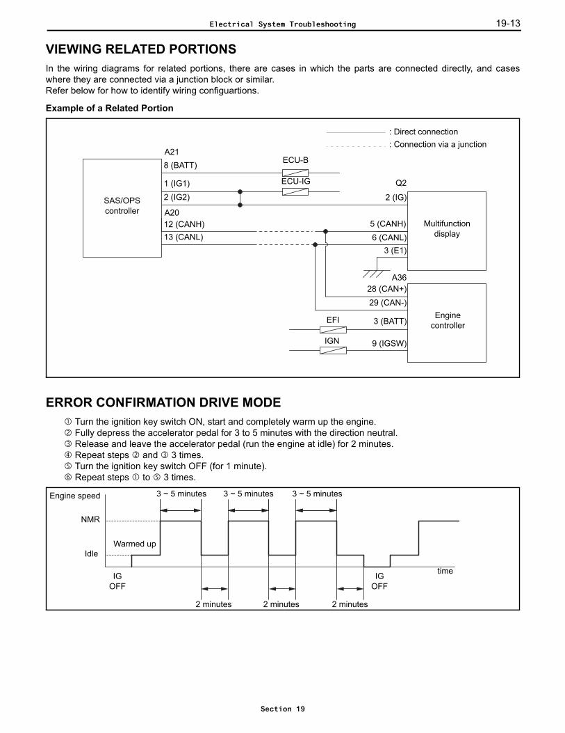
VIEWING RELATED PORTIONSIn the wiring diagrams for related portions, there are cases in which the parts are connected directly, and caseswhere they are connected via a junction block or similar. Refer below for how to identify wiring configuartions.
Example of a Related Portion
ERROR CONFIRMATION DRIVE MODE Turn the ignition key switch ON, start and completely warm up the engine. Fully depress the accelerator pedal for 3 to 5 minutes with the direction neutral. Release and leave the accelerator pedal (run the engine at idle) for 2 minutes. Repeat steps and 3 times. Turn the ignition key switch OFF (for 1 minute). Repeat steps to 3 times.
Enginecontroller
SAS/OPScontroller
8 (BATT)A21
1 (IG1)
28 (CAN+)29 (CAN-)
A36
Multifunction display
3 (BATT)
9 (IGSW)
2 (IG)
5 (CANH)
Q2
6 (CANL)3 (E1)
2 (IG2)
12 (CANH)13 (CANL)
: Direct connection: Connection via a junction
ECU-B
ECU-IG
EFI
IGN
A20
Engine speed
Idle
3 ~ 5 minutes 3 ~ 5 minutes 3 ~ 5 minutes
2 minutes 2 minutes 2 minutes
Warmed up
time
NMR
IGOFF
IGOFF
Electrical System Troubleshooting
Section 19
19-1419-14
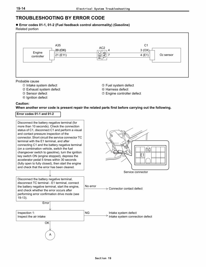
TROUBLESHOOTING BY ERROR CODE Error codes 01-1, 01-2 (Fuel feedback control abnormality) (Gasoline)
Related portion
Probable cause Intake system defect Fuel system defect Exhaust system defect Harness defect Sensor defect Engine controller defect Ignition defect
Caution:When another error code is present repair the related parts first before carrying out the following.
Error codes 01-1 and 01-2
TA
B
RE
CEnginecontroller O2 sensor
C120 (OX) 3 (OX)21 (E11) 4 (E1)
A3520 (OX) 4
7
AC2
Disconnect the battery negative terminal, disconnect TC terminal - E1 terminal, connect the battery negative terminal, start the engine, and check whether the error occurs after performing error confirmation drive mode (see 19-13).
No error
Error
NGInspection 1:Inspect the air intake
OK
Intake system defectIntake system connection defect
A
Disconnect the battery negative terminal (for more than 10 seconds). Check the connection status of C1, disconnect C1 and perform a visual and contact pressure inspection of the connector. Short circuit the service connector TC terminal with the E1 terminal, and after connecting C1 and the battery negative terminal (on a combination vehicle, switch the fuel changeover switch to gasoline), turn the ignition key switch ON (engine stopped), depress the accelerator pedal 5 times within 30 seconds (fully open to fully closed), then start the engine and check that the error has been cleared.
Service connector
Connector contact defect
Electrical System Troubleshooting
Section 19
19-15
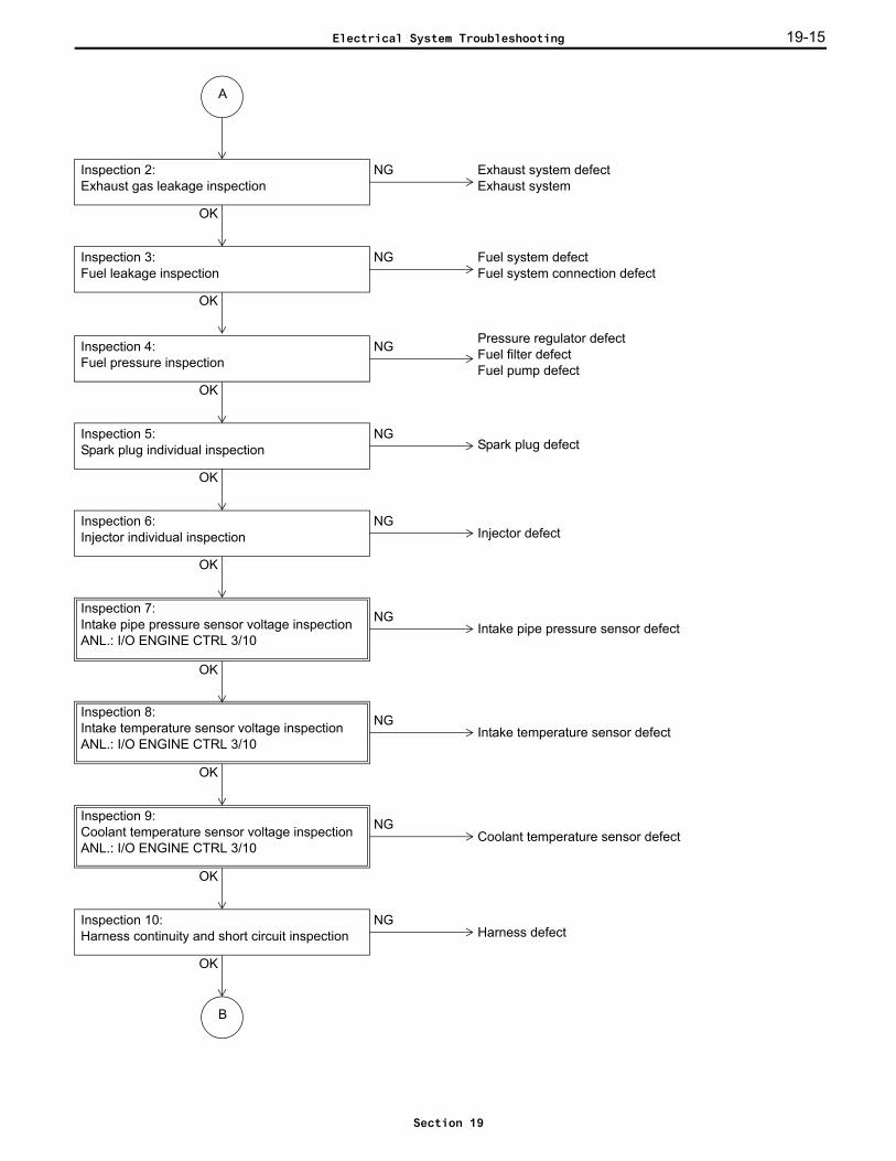
NGIntake pipe pressure sensor defect
Pressure regulator defectFuel filter defectFuel pump defect
NGInspection 4:Fuel pressure inspection
OK
NGInspection 5:Spark plug individual inspection
OK
Spark plug defect
NGInspection 6:Injector individual inspection
OK
Injector defect
OK
Inspection 7:Intake pipe pressure sensor voltage inspectionANL.: I/O ENGINE CTRL 3/10
NG
OK
Intake temperature sensor defectInspection 8:Intake temperature sensor voltage inspectionANL.: I/O ENGINE CTRL 3/10
A
NG
OK
Coolant temperature sensor defectInspection 9:Coolant temperature sensor voltage inspectionANL.: I/O ENGINE CTRL 3/10
NGInspection 10:Harness continuity and short circuit inspection
OK
Harness defect
NGInspection 3:Fuel leakage inspection
OK
Fuel system defectFuel system connection defect
NGInspection 2:Exhaust gas leakage inspection
Exhaust system defectExhaust system
OK
B
Electrical System Troubleshooting
Section 19

19-1619-16
Inspection 1: Inspect for air suction.
Start the engine and check whether air is being sucked in from the engine oil level gauge, oil filler cap, or PCVhose etc.
Standard: There is no air being sucked in.Check if there is air being sucked in from the intake system parts and connections between the air cleaner andthe cylinder head.
Standard: There is no air being sucked in.
Inspection 2: Inspect for exhaust gas leakage.
Start the engine and check if there is any exhaust gas leakage from the exhaust system parts and connectionsbetween the cylinder head and the catalytic muffler.
Standard: There is no exhaust gas leakage.
Inspection 3: Inspect for fuel leakage.
Start the engine and check if there is any fuel leakage from the fuel system parts and connections between thefuel pump and the injectors.
Standard: There is no fuel leakage.
Inspection 4: Inspect the fuel pressure.
For the fuel pressure inspection, refer to the repair manual for the 4Y engine.
Inspection 5: Carry out a spark plug individual inspection.
For the spark plug individual inspection, refer to the repair manual for the 4Y engine.
Inspection 6: Carry out an injector individual inspection.
For the individual injector inspection, refer to the repair manual for the 4Y engine.
NG
OK
Engine controller defectInspection 12:O2 sensor voltage inspectionANL.:I/O ENGINE CTRL 9/10
O2 sensor defect
B
OK
NG
Connector contact defectInspection 11:O2 sensor voltage inspectionANL.:I/O ENGINE CTRL 9/10
Electrical System Troubleshooting
Section 19

19-17
Inspection 7: Inspect the intake pipe pressure sensor voltage.
Ignition key switch ON, engine stoppedIntake pipe pressure sensor voltage (I/O monitor: PIM)
Standard:
Inspection 8: Inspect the intake temperature sensor voltage.Ignition key switch ON, engine stopped
Intake temperature sensor voltage (I/O monitor: THA)
Standard:
Inspection 9: Inspect the coolant temperature sensor voltage.Start the engine, warm up completely (coolant temperature gauge: at 5-6 bars)
Coolant temperature sensor voltage (I/O monitor: THW)
Standard:
Inspection 10: Inspect for continuity and short circuiting of the harness.
Ignition key switch OFF, disconnect battery negative terminal, disconnect A35 and C1.
Standard:
Inspection 11: Inspect the O2 sensor output.
Connect A35 and C1, start the engine, warm up completely, set direction in neutral, fully open the acceleratorpedalO2 sensor voltage (I/O monitor: OX)
Standard:
Inspection 12: Inspect the O2 sensor output.
Disconnect C1, connect A35, start the engine, warm up completely, set direction in neutral, fully open theaccelerator pedalO2 sensor voltage (I/O monitor: OX)
Standard:
PIM 3.6 ± 0.3 V (100 ± 10 kPa (1 ± 0.1 kgf/cm2) [14 ± 1.4 psi])
THA2.4 ± 0.6 V (20 ± 10°C)
0.55 ± 0.15 V (80 ± 10°C) (reference value)
THW0.55 ± 0.15 V (80 ± 10°C)
2.4 ± 0.6 V (20 ± 10°C) (reference value)
A35-20 ~ C1-3 Continuity
A35-21 ~ C1-4 Continuity
A35-20 ~ Frame No continuity
OX 0.4 V or less and 0.5 V or more alternately output
OX 0.2 V or less
Electrical System Troubleshooting
Section 19

19-1819-18
Error codes 01-3, 01-4 (Fuel feedback control abnormality) (LPG/CNG)Related portion
Probable cause Intake system defect Fuel system defect Exhaust system defect Harness defect Sensor defect Engine controller defect Ignition defect
Caution:When another error code is occuring, repair the related parts first before carrying out the following.
Error codes 01-3 and 01-4TA
B
RE
CEnginecontroller O2 sensor
C120 (OX) 3 (OX)21 (E11) 4 (E1)
A3520 (OX) 4
7
AC2
Disconnect the battery negative terminal, disconnect TC terminal - E1 terminal, connect the battery negative terminal, start the engine, and check whether the error occurs after performing error confirmation drive mode (see 19-13).
No error
Error
NGInspection 1:Inspect the air intake
OK
Intake system defectIntake system connection defect
A
Disconnect the battery negative terminal (for more than 10 seconds). Check the connection status of C1, disconnect C1 and perform a visual and contact pressure inspection of the connector. Short circuit the service connector TC terminal with the E1 terminal, and after connecting C1 and the battery negative terminal (on a combination vehicle, switch the fuel changeover switch to gasoline), turn the ignition key switch ON (engine stopped), depress the accelerator pedal 5 times within 30 seconds (fully open to fully closed), then start the engine and check that the error has been cleared.
Connector contact defect
Service connector
Electrical System Troubleshooting
Section 19

19-19
NGInspection 11:Harness continuity and short circuit inspection
OK
Harness defect
Regulator defectNGInspection 4:
Regulator primary pressure inspection
OK
NGInspection 5:Spark plug individual inspection
OK
Spark plug defect
NGInspection 6:Injector individual inspection
OK
Injector defect
NG
OK
Intake pipe pressure sensor defectInspection 8:Intake pipe pressure sensor voltage inspectionANL.: I/O ENGINE CTRL 3/10
NG
OK
Intake temperature sensor defectInspection 9:Intake temperature sensor voltage inspectionANL.: I/O ENGINE CTRL 3/10
A
NG
OK
Water temperature sensor defectInspection 10:Water temperature sensor voltage inspectionANL.: I/O ENGINE CTRL 3/10
NGInspection 3:Fuel leakage inspection
OK
Fuel system defectFuel system connection defect
NGInspection 2:Exhaust gas leakage inspection
Exhaust system defectExhaust system connection defect
OK
B
NGInspection 7:Air-fuel ratio motor individual inspection
OK
Air-fuel ratio motor defect
Electrical System Troubleshooting
Section 19

19-2019-20
Inspection 1: Inspect for air suction.
Start the engine and check whether air is being sucked in from the engine oil level gauge, oil filler cap, or PCVhose etc.
Standard: There is no air being sucked in.Check if there is air being sucked in from the intake system parts and connections between the air cleaner andthe regulator.
Standard: There is no air being sucked in.Check if there is air being sucked in from the intake system parts and connections among the air cleaner hose,the resonator, and the regulator.
Standard: There is no air being sucked in.
Inspection 2: Inspect for exhaust gas leakage.
Start the engine and check if there is any exhaust gas leakage from the exhaust system parts and connectionsbetween the cylinder head and the catalytic muffler.
Standard: There is no exhaust gas leakage.
Inspection 3: Inspect for fuel leakage.
Start the engine and check if there is any fuel leakage from the fuel system parts and connections between thefuel tank and the regulator.
Standard: There is no fuel leakage.Check if there is fuel leakage from the fuel system parts and connections between the regulator and the LPGadapter.
Standard: There is no fuel leakage.Check if there is fuel leakage from the fuel system parts and connections between the regulator and the injector.
Standard: There is no fuel leakage.
Inspection 4: Inspect the regulator primary pressure.
For the regulator primary pressure inspection, refer to the LPG repair manual.
NG
OK
Engine controller defectInspection 13:O2 sensor voltage inspectionANL.:I/O ENGINE CTRL 9/10
O2 sensor defect
B
OK
NG
Connector contact defectInspection 12:O2 sensor voltage inspectionANL.:I/O ENGINE CTRL 9/10
Electrical System Troubleshooting
Section 19

19-21
Inspection 5: Carry out a spark plug individual inspection.
For the spark plug individual inspection, refer to the repair manual for the 4Y engine.
Inspection 6: Carry out an injector individual inspection.
For the individual injector inspection, refer to the repair manual for the 4Y engine.
Inspection 7: Carry out an individual inspection of the air-fuel ratio motor.
For the individual air-fuel ratio motor inspection, refer to the LPG repair manual.
Inspection 8: Inspect the intake pipe pressure sensor voltage.
Ignition key switch ON, engine stoppedIntake pipe pressure sensor voltage (I/O monitor: PIM)
Standard:
Inspection 9: Inspect the intake temperature sensor voltage.
Ignition key switch ON, engine stoppedIntake temperature sensor voltage (I/O monitor: THA)
Standard:
Inspection 10: Inspect the coolant temperature sensor voltage.
Start the engine, warm up completely (coolant temperature gauge: 5-6 bars)Coolant temperature sensor voltage (I/O monitor: THW)
Standard:
Inspection 11: Inspect for continuity and short circuiting of the harness.
Ignition key switch OFF, disconnect A35 and C1
Standard:
PIM 3.6 ± 0.3 V (100 ± 10 kPa (1 ± 0.1 kgf/cm2) [14 ± 1.4 psi])
THA2.4 ± 0.6 V (20 ± 10°C)
0.55 ± 0.15 V (80 ± 10°C) (reference value)
THW0.55 ± 0.15 V (80 ± 10°C)
2.4 ± 0.6 V (20 ± 10°C) (reference value)
A35-20 ~ C1-3 Continuity
A35-21 ~ C1-4 Continuity
A35-20 ~ Frame No continuity
Electrical System Troubleshooting
Section 19

19-2219-22
Inspection 12: Inspect the O2 sensor output.
Start the engine, warm up completely, put the direction in neutral, fully open the accelerator pedalO2 sensor voltage (I/O monitor: OX)
Standard:
Inspection 13: Inspect the O2 sensor output.
Start the engine, warm up completely, put the direction in neutral, fully open the accelerator pedalO2 sensor voltage (I/O monitor: OX)
Standard:
OX 0.4 V or less and 0.5 V or more alternately output
OX 0.2 V or less
Electrical System Troubleshooting
Section 19
19-23
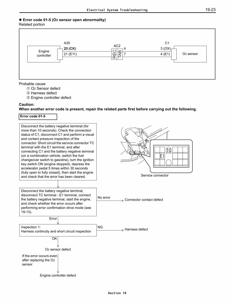
Error code 01-5 (O2 sensor open abnormality)Related portion
Probable cause O2 Sensor defect Harness defect Engine controller defect
Caution:When another error code is present, repair the related parts first before carrying out the following.
Error code 01-5TA
B
RE
CEnginecontroller O2 sensor
C120 (OX) 3 (OX)21 (E11) 4 (E1)
A3520 (OX) 4
7
AC2
NGInspection 1:Harness continuity and short circuit inspection
If the error occurs even after replacing the O2 sensor
Harness defect
O2 sensor defect
OK
Engine controller defect
Disconnect the battery negative terminal, disconnect TC terminal - E1 terminal, connect the battery negative terminal, start the engine, and check whether the error occurs after performing error confirmation drive mode (see 19-13).
No error
Error
Disconnect the battery negative terminal (for more than 10 seconds). Check the connection status of C1, disconnect C1 and perform a visual and contact pressure inspection of the connector. Short circuit the service connector TC terminal with the E1 terminal, and after connecting C1 and the battery negative terminal (on a combination vehicle, switch the fuel changeover switch to gasoline), turn the ignition key switch ON (engine stopped), depress the accelerator pedal 5 times within 30 seconds (fully open to fully closed), then start the engine and check that the error has been cleared.
Connector contact defect
Service connector
Electrical System Troubleshooting
Section 19

19-2419-24
Inspection 1: Inspect for continuity and short circuiting of the harness.
Ignition key switch OFF, disconnect A35 and C1
Standard:A35-20 ~ C1-3 Continuity
A35-21 ~ C1-4 Continuity
A35-20 ~ Frame No continuity
Electrical System Troubleshooting
Section 19
19-25
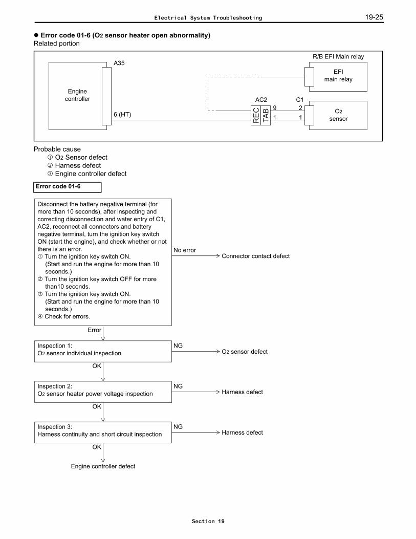
Error code 01-6 (O2 sensor heater open abnormality)Related portion
Probable cause O2 Sensor defect Harness defect Engine controller defect
Error code 01-6
TA
B
RE
C
Enginecontroller
A35
6 (HT)9 O2
sensor
C1
12
R/B EFI Main relay
EFImain relay
AC2
1
No errorConnector contact defect
Disconnect the battery negative terminal (for more than 10 seconds), after inspecting and correcting disconnection and water entry of C1, AC2, reconnect all connectors and battery negative terminal, turn the ignition key switch ON (start the engine), and check whether or not there is an error.
Turn the ignition key switch ON.(Start and run the engine for more than 10 seconds.)
Turn the ignition key switch OFF for more than10 seconds.
Turn the ignition key switch ON.(Start and run the engine for more than 10 seconds.)
Check for errors.
NGInspection 1:O2 sensor individual inspection O2 sensor defect
OK
NGInspection 2:O2 sensor heater power voltage inspection Harness defect
OK
NGInspection 3:Harness continuity and short circuit inspection Harness defect
Engine controller defect
OK
Error
Electrical System Troubleshooting
Section 19
19-2619-26
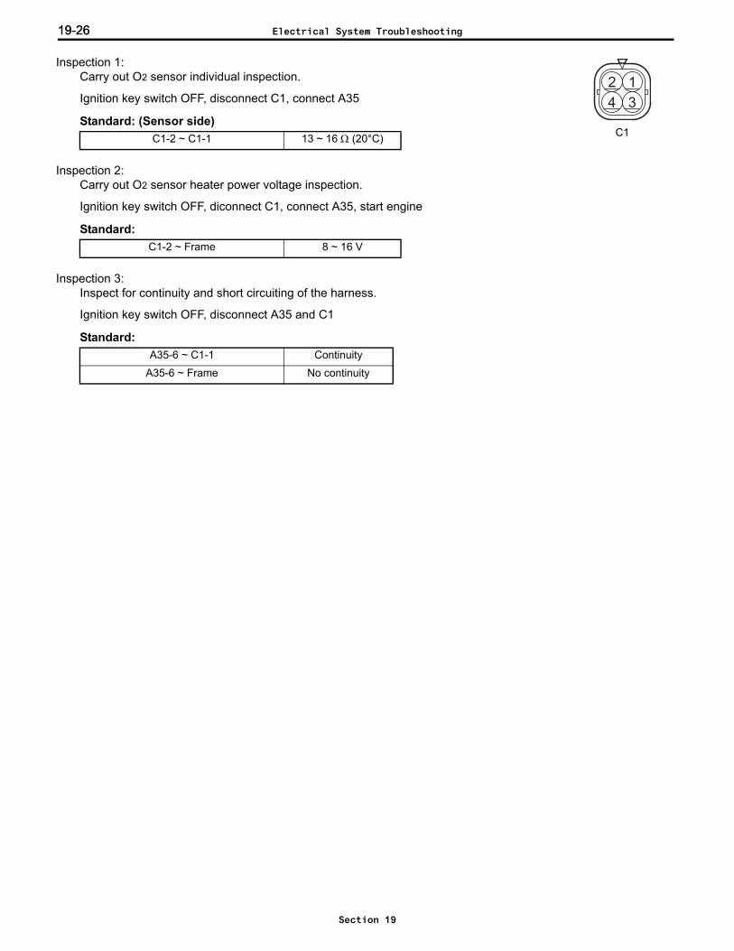
Inspection 1: Carry out O2 sensor individual inspection.
Ignition key switch OFF, disconnect C1, connect A35
Standard: (Sensor side)
Inspection 2: Carry out O2 sensor heater power voltage inspection.
Ignition key switch OFF, diconnect C1, connect A35, start engine
Standard:
Inspection 3: Inspect for continuity and short circuiting of the harness.
Ignition key switch OFF, disconnect A35 and C1
Standard:
C1-2 ~ C1-1 13 ~ 16 Ω (20°C)
C1-2 ~ Frame 8 ~ 16 V
A35-6 ~ C1-1 Continuity
A35-6 ~ Frame No continuity
12
34
C1
Electrical System Troubleshooting
Section 19
19-27
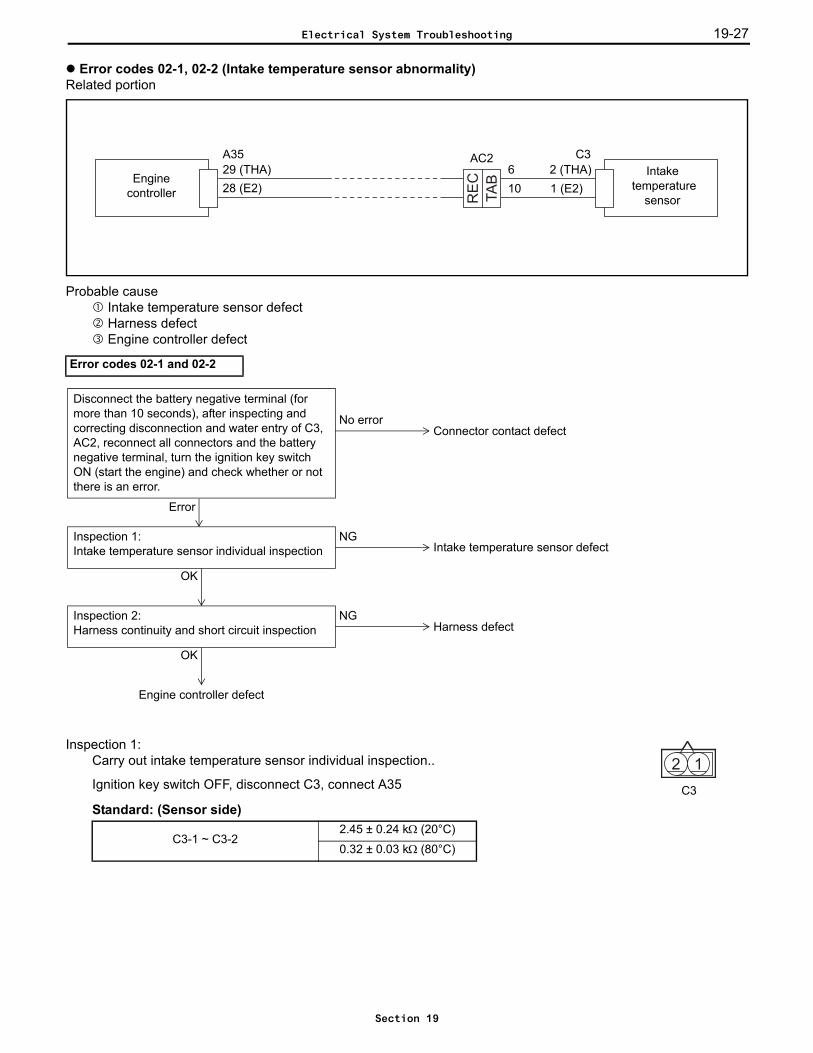
Error codes 02-1, 02-2 (Intake temperature sensor abnormality)Related portion
Probable cause Intake temperature sensor defect Harness defect Engine controller defect
Inspection 1: Carry out intake temperature sensor individual inspection..
Ignition key switch OFF, disconnect C3, connect A35
Standard: (Sensor side)
Error codes 02-1 and 02-2
C3-1 ~ C3-22.45 ± 0.24 kΩ (20°C)
0.32 ± 0.03 kΩ (80°C)
TA
B
RE
CEnginecontroller
A35 C329 (THA) 2 (THA)28 (E2) 1 (E2)
Intake temperature
sensor
610
AC2
NGInspection 1:Intake temperature sensor individual inspection Intake temperature sensor defect
OK
Engine controller defect
NGInspection 2:Harness continuity and short circuit inspection Harness defect
OK
Error
No errorConnector contact defect
Disconnect the battery negative terminal (for more than 10 seconds), after inspecting and correcting disconnection and water entry of C3, AC2, reconnect all connectors and the battery negative terminal, turn the ignition key switch ON (start the engine) and check whether or not there is an error.
12
C3
Electrical System Troubleshooting
Section 19

19-2819-28
Inspection 2: Inspect for continuity and short circuiting of the harness.
Ignition key switch OFF, disconnect A35 and C3
Standard:A35-29 ~ C3-2 Continuity
A35-28 ~ C3-1 Continuity
A35-29 ~ Frame No continuity
Electrical System Troubleshooting
Section 19
19-29
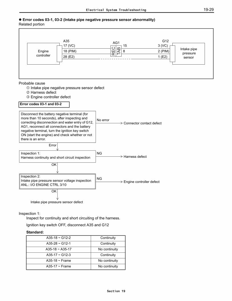
Error codes 03-1, 03-2 (Intake pipe negative pressure sensor abnormality)Related portion
Probable cause Intake pipe negative pressure sensor defect Harness defect Engine controller defect
Inspection 1: Inspect for continuity and short circuiting of the harness.
Ignition key switch OFF, disconnect A35 and G12
Standard:
Error codes 03-1 and 03-2
A35-18 ~ G12-2 Continuity
A35-28 ~ G12-1 Continuity
A35-18 ~ A35-17 No continuity
A35-17 ~ G12-3 Continuity
A35-18 ~ Frame No continuity
A35-17 ~ Frame No continuity
TA
B
RE
C
Enginecontroller
A3517 (VC)18 (PIM)28 (E2)
3 (VC)G12
2 (PIM)1 (E2)
Intake pipe pressure
sensor
158
AG1
Error
Intake pipe pressure sensor defect
Engine controller defectNG
OK
Inspection 2:Intake pipe pressure sensor voltage inspectionANL.: I/O ENGINE CTRL 3/10
NGInspection 1:Harness continuity and short circuit inspection Harness defect
OK
No errorConnector contact defect
Disconnect the battery negative terminal (for more than 10 seconds), after inspecting and correcting disconnection and water entry of G12, AG1, reconnect all connectors and the battery negative terminal, turn the ignition key switch ON (start the engine) and check whether or not there is an error.
Electrical System Troubleshooting
Section 19

19-3019-30
Inspection 2: Inspect the intake pipe pressure sensor voltage.
Ignition key switch OFF, disconnect G12, connect A35, ignition key switch ON, engine stoppedIntake pipe pressure sensor voltage (I/O monitor: PIM)
Standard:PIM 4.80 V or more
Electrical System Troubleshooting
Section 19
19-31
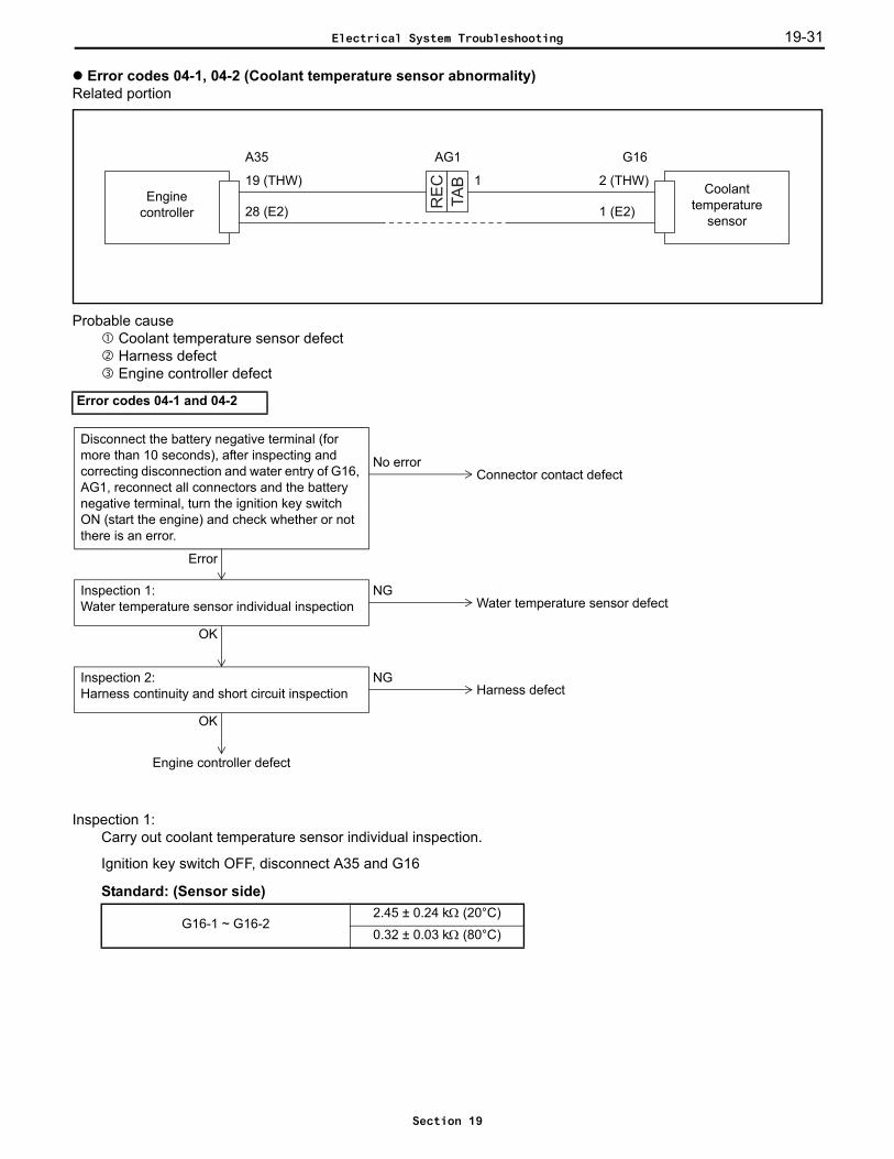
Error codes 04-1, 04-2 (Coolant temperature sensor abnormality)Related portion
Probable cause Coolant temperature sensor defect Harness defect Engine controller defect
Inspection 1: Carry out coolant temperature sensor individual inspection.
Ignition key switch OFF, disconnect A35 and G16
Standard: (Sensor side)
Error codes 04-1 and 04-2
G16-1 ~ G16-22.45 ± 0.24 kΩ (20°C)
0.32 ± 0.03 kΩ (80°C)
TA
B
RE
C
Enginecontroller
Coolant temperature
sensor
A35
19 (THW) 2 (THW)
28 (E2) 1 (E2)
G16
1
AG1
Error
NGInspection 1:Water temperature sensor individual inspection Water temperature sensor defect
OK
Engine controller defect
NGInspection 2:Harness continuity and short circuit inspection Harness defect
OK
No errorConnector contact defect
Disconnect the battery negative terminal (for more than 10 seconds), after inspecting and correcting disconnection and water entry of G16, AG1, reconnect all connectors and the battery negative terminal, turn the ignition key switch ON (start the engine) and check whether or not there is an error.
Electrical System Troubleshooting
Section 19

19-3219-32
Inspection 2: Inspect for continuity and short circuiting of the harness.
Ignition key switch OFF, disconnect A35 and G16
Standard:A35-19 ~ G16-2 Continuity
A35-28 ~ G16-1 Continuity
A35-19 ~ Frame No continuity
Electrical System Troubleshooting
Section 19

19-33
Error codes 05-1, 05-2, 05-3, 05-4, 05-5, 05-6 (Throttle position sensor abnormality)Related portion
Probable cause Throttle position sensor defect Harness defect Engine controller defect
Error codes 05-1, 05-2, 05-3, 05-4, 05-5, 05-6
G6
Enginecontroller
G2720 (VC2)21 (VTA)29 (VTA2)28 (E21)
4 (VTA2)3 (E2)
Throttleposition sensor
5 (VC)6 (VTA)
Error
Throttle position sensor defect
NG
OK
Engine controller defect
NGInspection 1:Harness continuity and short circuit inspection Harness defect
OK
No errorConnector contact defect
Disconnect the battery negative terminal (for more than 10 seconds), after inspecting and correcting disconnection and water entry of G6, reconnect all connectors and the battery negative terminal, turn the ignition key switch ON (start the engine) and check whether or not there is an error.
Inspection 2:Throttle position sensor voltage inspectionANL.: I/O ENGINE CTRL 5/10
Electrical System Troubleshooting
Section 19
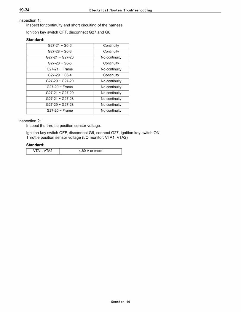
19-3419-34
Inspection 1: Inspect for continuity and short circuiting of the harness.
Ignition key switch OFF, disconnect G27 and G6
Standard:
Inspection 2: Inspect the throttle position sensor voltage.
Ignition key switch OFF, disconnect G6, connect G27, ignition key switch ONThrottle position sensor voltage (I/O monitor: VTA1, VTA2)
Standard:
G27-21 ~ G6-6 Continuity
G27-28 ~ G6-3 Continuity
G27-21 ~ G27-20 No continuity
G27-20 ~ G6-5 Continuity
G27-21 ~ Frame No continuity
G27-29 ~ G6-4 Continuity
G27-29 ~ G27-20 No continuity
G27-29 ~ Frame No continuity
G27-21 ~ G27-29 No continuity
G27-21 ~ G27-28 No continuity
G27-29 ~ G27-28 No continuity
G27-20 ~ Frame No continuity
VTA1, VTA2 4.80 V or more
Electrical System Troubleshooting
Section 19

19-35
Error codes 06-1, 06-2 (Throttle motor drive circuit open/short abnormality)Related portion
Probable cause Throttle motor defect Harness defect Engine controller defect
Error codes 06-1 and 06-2R
EC
TAB
2 (M+)1 (M-)
Enginecontroller
Throttlemotor
E-THRO
G277 (+BM)
6 (M+)5 (M-)4 (ME01)
G613
AG1
Error
NGInspection 1:Throttle motor individual inspection Throttle motor defect
OK
NGInspection 2:Harness continuity and short circuit inspection Harness defect
OK
Engine controller defect
No errorConnector contact defect
Disconnect the battery negative terminal (for more than 10 seconds), after inspecting and correcting disconnection and water entry of G6, AG1, reconnect all connectors and the battery negative terminal, turn the ignition key switch ON (start the engine) and check whether or not there is an error.
Electrical System Troubleshooting
Section 19
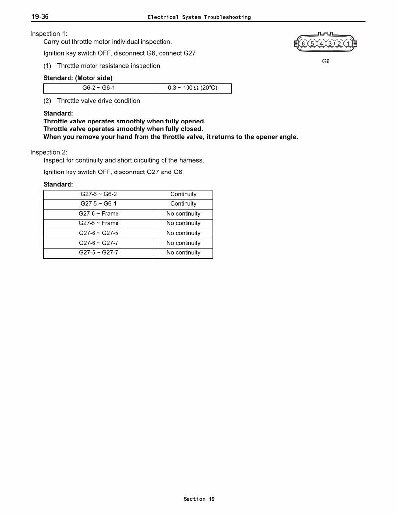
19-3619-36
Inspection 1: Carry out throttle motor individual inspection.
Ignition key switch OFF, disconnect G6, connect G27
(1) Throttle motor resistance inspection
Standard: (Motor side)
(2) Throttle valve drive condition
Standard:Throttle valve operates smoothly when fully opened.Throttle valve operates smoothly when fully closed.When you remove your hand from the throttle valve, it returns to the opener angle.
Inspection 2: Inspect for continuity and short circuiting of the harness.
Ignition key switch OFF, disconnect G27 and G6
Standard:
G6-2 ~ G6-1 0.3 ~ 100 Ω (20°C)
G27-6 ~ G6-2 Continuity
G27-5 ~ G6-1 Continuity
G27-6 ~ Frame No continuity
G27-5 ~ Frame No continuity
G27-6 ~ G27-5 No continuity
G27-6 ~ G27-7 No continuity
G27-5 ~ G27-7 No continuity
123456
G6
Electrical System Troubleshooting
Section 19

19-37
Error codes 06-3, 06-4 (Throttle motor power circuit open/short abnormality)Related portion
Probable cause Harness defect Engine controller defect
Inspection 1: Inspect the throttle motor power voltage.
Ignition key switch OFF, disconnect G27
Standard:
Error codes 06-3 and 06-4
G27-7 ~ Frame 8 ~ 16 V
RE
C
TA
BEnginecontroller
E-THRO
G27
7 (+BM)AG1
13
Error
NGInspection 1:Throttle motor power voltage inspection Harness defect
OK
Engine controller defect
No errorConnector contact defect
Disconnect the battery negative terminal (for more than 10 seconds), after inspecting and correcting disconnection and water entry of G27, AG1, reconnect all connectors and the battery negative terminal, turn the ignition key switch ON (start the engine) and check whether or not there is an error.
Electrical System Troubleshooting
Section 19

19-3819-38
Error code 06-5 (Throttle motor seized abnormality)Related portion
Probable cause Throttle motor defect Harness defect Engine controller defect
Inspection 1: Carry out throttle motor individual inspection.
Ignition key switch OFF, disconnect G6, connect G27
(1) Throttle motor resistance inspection
Standard: (Motor side)
(2) Throttle valve drive condition
Standard:Throttle valve operates smoothly when fully opened.Throttle valve operates smoothly when fully closed.When you remove your hand from the throttle valve, it returns to the opener angle
Error code 06-5
G6-2 ~ G6-1 0.3 ~ 100 Ω (20°C)
RE
CTA
B
2 (M+)1 (M-)
Enginecontroller
Throttlemotor
E-THRO
G277 (+BM)
6 (M+)5 (M-)4 (ME01)
G613
AG1
NGInspection 1:Throttle motor individual inspection Throttle motor defect
OK
NGInspection 2:Harness continuity and short circuit inspection Harness defect
OK
Engine controller defect
Error
No errorConnector contact defect
Disconnect the battery negative terminal (for more than 10 seconds), after inspecting and correcting disconnection and water entry of G6, AG1, reconnect all connectors and the battery negative terminal, turn the ignition key switch ON (start the engine) and check whether or not there is an error.
123456
G6
Electrical System Troubleshooting
Section 19

19-39
Inspection 2: Inspect for continuity and short circuiting of the harness.
Ignition key switch OFF, disconnect G6 and G27
Standard:G27-6 ~ G27-5 No continuity
G27-6 ~ G27-7 No continuity
G27-5 ~ G27-7 No continuity
Electrical System Troubleshooting
Section 19
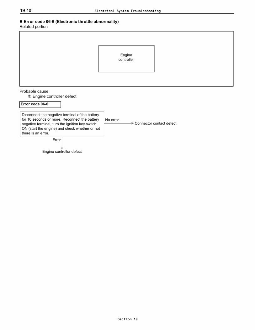
19-4019-40
Error code 06-6 (Electronic throttle abnormality)Related portion
Probable cause Engine controller defect
Error code 06-6
Enginecontroller
Engine controller defect
No errorDisconnect the negative terminal of the battery for 10 seconds or more. Reconnect the battery negative terminal, turn the ignition key switch ON (start the engine) and check whether or not there is an error.
Connector contact defect
Error
Electrical System Troubleshooting
Section 19

19-41
Error code 07-1 (Air-fuel ratio motor open abnormality)Related portion
Probable cause Air-fuel ratio motor defect Harness defect Engine controller defect
Error code 07-1
Enginecontroller
Air-fuel ratio
motor
EFImain relay
21 (FCM1)31 (FCM2)20 (FCM3)
30 (FCM4)
3 (FCM1)6 (FCM2)1 (FCM3)
4 (FCM4)
2 (B1)5 (B2)
R/B EFI Main relay
3 (L)
G13
G28
NGInspection 1:Air-fuel ratio motor individual inspection Air-fuel ratio motor defect
OK
NGInspection 2:Harness continuity and short circuit inspection Harness defect
OK
Engine controller defect
Error
No errorConnector contact defect
Disconnect the battery negative terminal (for more than 10 seconds), after inspecting and correcting disconnection and water entry of G13, reconnect all connectors and the battery negative terminal, turn the ignition key switch ON (start the engine) and check whether or not there is an error.
Electrical System Troubleshooting
Section 19
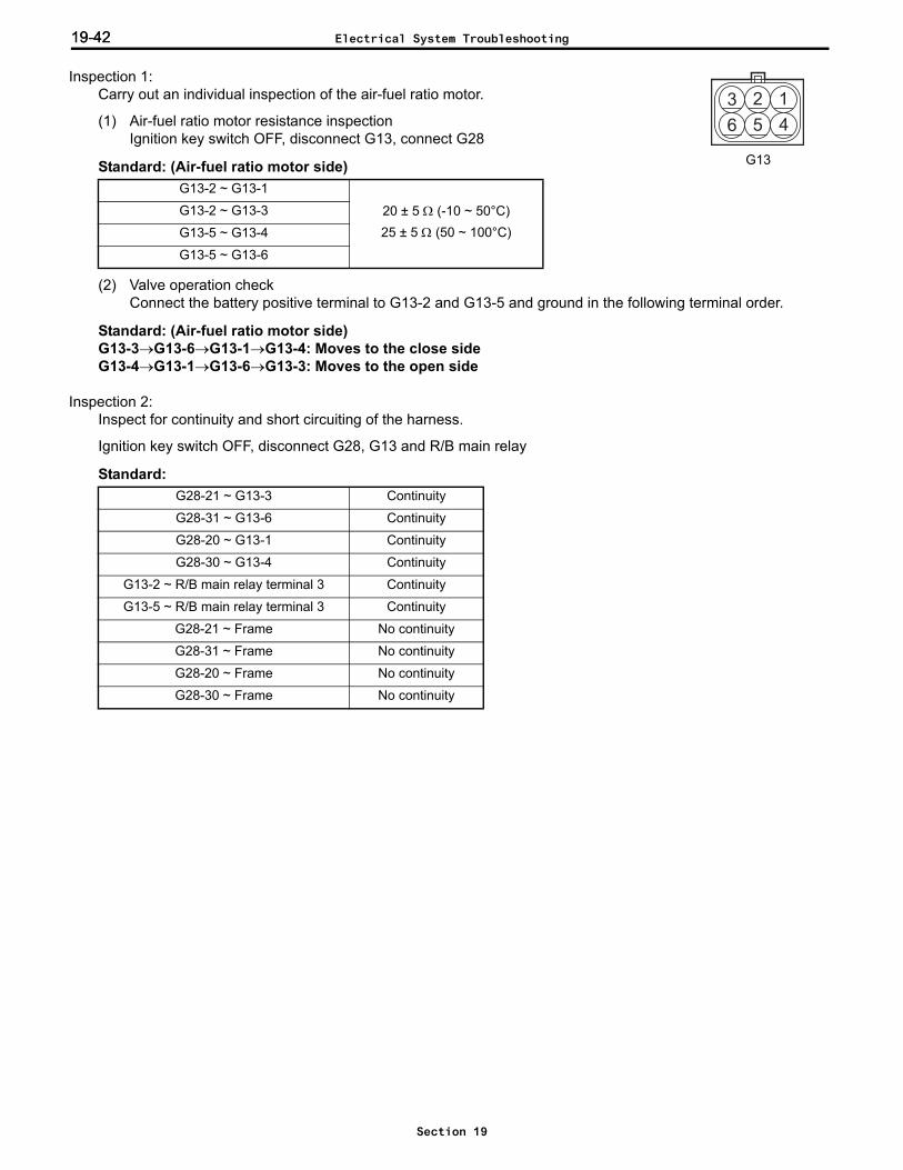
19-4219-42
Inspection 1: Carry out an individual inspection of the air-fuel ratio motor.
(1) Air-fuel ratio motor resistance inspectionIgnition key switch OFF, disconnect G13, connect G28
Standard: (Air-fuel ratio motor side)
(2) Valve operation checkConnect the battery positive terminal to G13-2 and G13-5 and ground in the following terminal order.
Standard: (Air-fuel ratio motor side)G13-3→G13-6→G13-1→G13-4: Moves to the close sideG13-4→G13-1→G13-6→G13-3: Moves to the open side
Inspection 2: Inspect for continuity and short circuiting of the harness.
Ignition key switch OFF, disconnect G28, G13 and R/B main relay
Standard:
G13-2 ~ G13-1
20 ± 5 Ω (-10 ~ 50°C)25 ± 5 Ω (50 ~ 100°C)
G13-2 ~ G13-3
G13-5 ~ G13-4
G13-5 ~ G13-6
G28-21 ~ G13-3 Continuity
G28-31 ~ G13-6 Continuity
G28-20 ~ G13-1 Continuity
G28-30 ~ G13-4 Continuity
G13-2 ~ R/B main relay terminal 3 Continuity
G13-5 ~ R/B main relay terminal 3 Continuity
G28-21 ~ Frame No continuity
G28-31 ~ Frame No continuity
G28-20 ~ Frame No continuity
G28-30 ~ Frame No continuity
3 2 1
6 5 4
G13
Electrical System Troubleshooting
Section 19
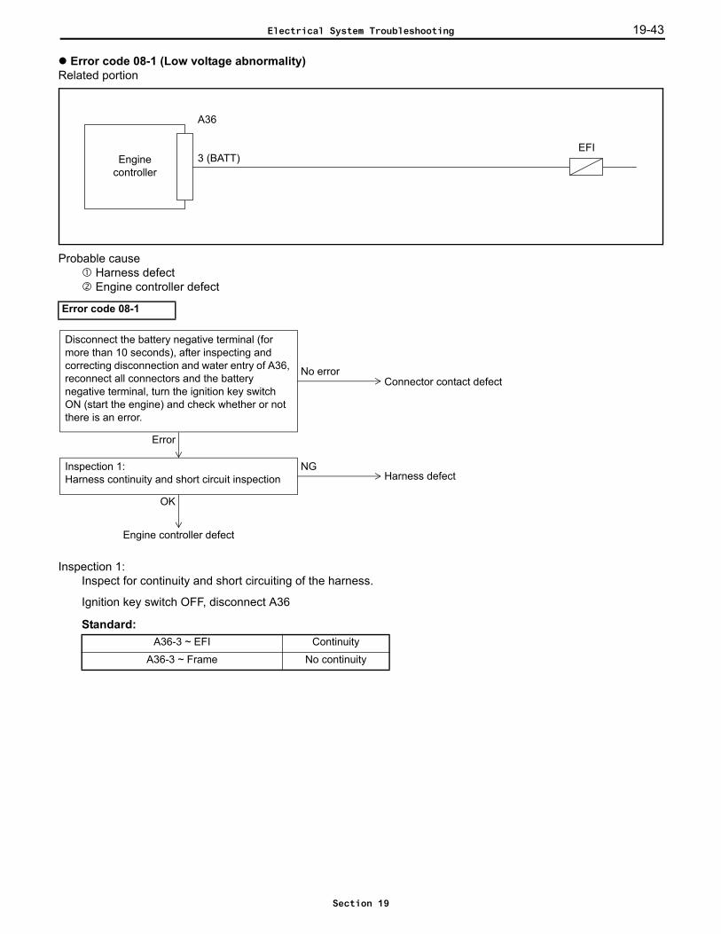
19-43
Error code 08-1 (Low voltage abnormality)Related portion
Probable cause Harness defect Engine controller defect
Inspection 1: Inspect for continuity and short circuiting of the harness.
Ignition key switch OFF, disconnect A36
Standard:
Error code 08-1
A36-3 ~ EFI Continuity
A36-3 ~ Frame No continuity
Enginecontroller
EFI
A36
3 (BATT)
NGInspection 1:Harness continuity and short circuit inspection Harness defect
OK
Engine controller defect
Error
No errorConnector contact defect
Disconnect the battery negative terminal (for more than 10 seconds), after inspecting and correcting disconnection and water entry of A36, reconnect all connectors and the battery negative terminal, turn the ignition key switch ON (start the engine) and check whether or not there is an error.
Electrical System Troubleshooting
Section 19

19-4419-44
Error code 09-1 (Ignition signal abnormality)Related portion
Probable cause Ignition coil Igniter defect Harness defect Engine controller defect
Enginecontroller
Igniter
Ignition coil
G27
G21
G25
33 (IGT)32 (IGF)
3 (IG2)5 (IG1)
2 (IG-)1 (IG+)
2 (IGT)1 (IGF)
IGN
Electrical System Troubleshooting
Section 19

19-45
Inspection 1: Carry out an ignition signal (IGF) inspection.
Ignition key switch OFF, disconnect G25, connect G27, ignition key switch ON, enginestopped
Standard:
Error code 09-1
G25-1 ~ Frame 4.0 ~ 5.5 V
Disconnect the battery negative terminal (for more than 10 seconds), after inspecting and correcting disconnection of G21 and G25 and internal leakage, reconnect all connectors and the battery negative terminal, turn the ignition key switch ON to start the engine.
Engine will not start
Enginestarts
Operate the accelerator pedal and check whether there is an error.
Error
No errorConnector contact defect
OK
Igniter defect
NGInspection 1:Ignition abnormality signal (IGF) inspection
Harness defect
OK
Engine controller defect
NGInspection 2:Harness continuity and short circuit inspection
Ignition coil defect
OK
NGInspection 3:Ignition coil individual inspection
Harness defect
OK
NGInspection 4:Harness continuity and short circuit inspection
Engine controller defectNG
OK
Igniter defect
Inspection 5:Igniter IGT signal inspection
OKOKOK
12345
G25
Electrical System Troubleshooting
Section 19
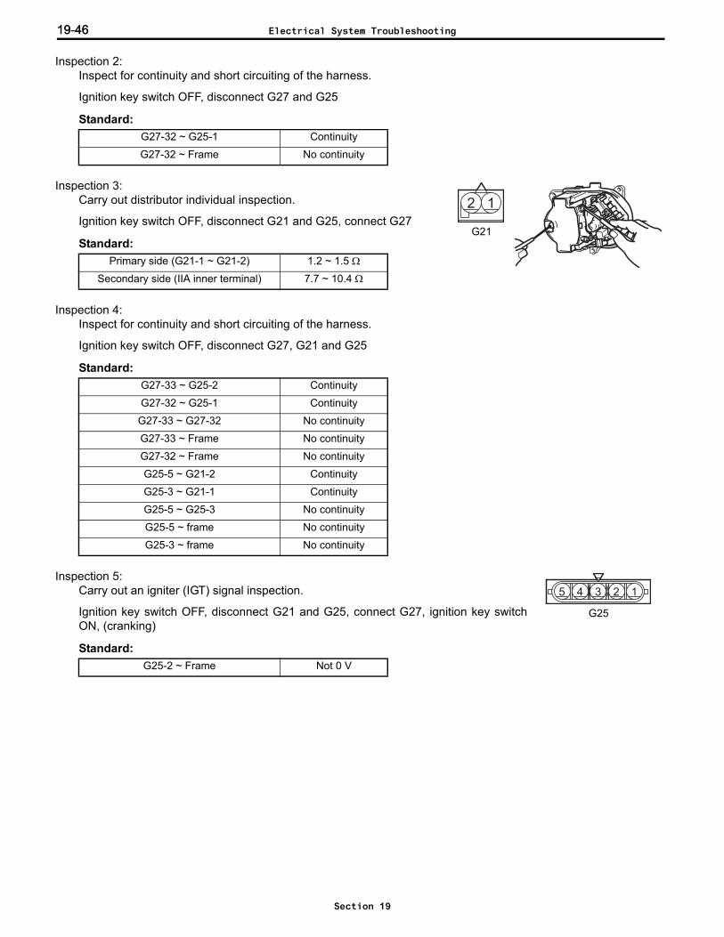
19-4619-46
Inspection 2: Inspect for continuity and short circuiting of the harness.
Ignition key switch OFF, disconnect G27 and G25
Standard:
Inspection 3: Carry out distributor individual inspection.
Ignition key switch OFF, disconnect G21 and G25, connect G27
Standard:
Inspection 4: Inspect for continuity and short circuiting of the harness.
Ignition key switch OFF, disconnect G27, G21 and G25
Standard:
Inspection 5: Carry out an igniter (IGT) signal inspection.
Ignition key switch OFF, disconnect G21 and G25, connect G27, ignition key switchON, (cranking)
Standard:
G27-32 ~ G25-1 Continuity
G27-32 ~ Frame No continuity
Primary side (G21-1 ~ G21-2) 1.2 ~ 1.5 Ω
Secondary side (IIA inner terminal) 7.7 ~ 10.4 Ω
G27-33 ~ G25-2 Continuity
G27-32 ~ G25-1 Continuity
G27-33 ~ G27-32 No continuity
G27-33 ~ Frame No continuity
G27-32 ~ Frame No continuity
G25-5 ~ G21-2 Continuity
G25-3 ~ G21-1 Continuity
G25-5 ~ G25-3 No continuity
G25-5 ~ frame No continuity
G25-3 ~ frame No continuity
G25-2 ~ Frame Not 0 V
12
G21
12345
G25
Electrical System Troubleshooting
Section 19

19-47
Error code 0A-1, 0A-2, 0A-3 (Fuel specification determination abnormality)Related portion
Probable cause Fuel changeover switch defect Harness defect Engine controller defect
Error codes 0A-1, 0A-2, 0A-3
Enginecontroller
14 (GAS)13 (LPG)
G28
G2715 (SEL1)
14 (SEL2)
13 (SEL3)12 (SEL4)10 (ESEL)
3 (GAS)1 (LPG) Fuel
changeover switch2 (IG)
3 (L) EFImain relay
G88
NGInspection 2:Fuel changeover switch individual inspection Fuel changeover switch defect
OK
NGInspection 3:Harness continuity and short circuit inspection Harness defect
OK
Engine controller defect
Error
No error Connector contact defect
Disconnect the battery negative terminal (for more than 10 seconds), after inspecting and correcting disconnection and water entry of G88, reconnect all connectors and the battery negative terminal, turn the ignition key switch ON (start the engine) and check whether or not there is an error.
OK
Inspection 1:Switch input signal inspectionANL.: I/O ENGINE CTRL 1/10
Electrical System Troubleshooting
Section 19

19-4819-48
Inspection 1: Carry out switch input signal inspection.
Ignition key switch ONSwitch input signal (I/O monitor: G/LP, SEL1-4)
Standard:
Inspection 2: Carry out fuel changeover switch individual inspection.(Carry out only for convertible vehicles, and only when the G/LP input in inspection 1 is outsidethe standard value)
Ignition key switch OFF, disconnect G88, connect G28 and G27
Standard: (Switch side)
Inspection 3: Inspect for continuity and short circuiting of the harness. (Begin with the place that was outside the standardvalue in inspection 1)
Ignition key switch OFF, disconnect G28, G27 and G88
Vehicle specification Fuel changeover switch G/LP SEL
Gasoline specification – 10 1100
LPG exclusive – 01 0101
LPG/Gasoline convertible
Gasoline selection 10
0110LPG selection 01
Neutral 00
Gasoline/CNG convertible
Gasoline selection 10
0101CNG selection 01
Neutral 00
Fuel changeover switch
Gasoline LPG/CNG Neutral
G88-2 ~ G88-3 Continuity No continuity No continuity
G88-2 ~ G88-1 No continuity Continuity No continuity
Vehicle specificationHarness
SEL1 SEL2 SEL3 SEL4
Gasoline specificationShort circuit to
ESELShort circuit to
ESEL– –
LPG exclusiveShort circuit to
ESELShort circuit to
ESELShort circuit to
ESEL–
LPG/Gasoline convertible –Short circuit to
ESELShort circuit to
ESEL–
Gasoline/CNG convertible –Short circuit to
ESEL–
Short circuit to ESEL
G88
Electrical System Troubleshooting
Section 19

19-49
Error code 0A-4 (Engine specification determination abnormality)Related portion
Probable cause Engine controller defect
Error code 0A-4
Enginecontroller
Engine controller defect
No errorNormal
Error
Disconnect the battery negative terminal (for 10 seconds or more), reconnect the battery negative terminal, then turn the ignition key switch ON (start the engine) and check whether or not there is an error.
Electrical System Troubleshooting
Section 19

19-5019-50
Error codes 13-1, 13-2, 13-3 (Relay abnormality)Related portion
Probable cause Connector contact defect ASC relay defect Harness defect ASC controller defect
Error codes 13-1, 13-2, 13-3R
EC
TA
B
RE
C
TA
B
ASC controller
G385 (SRLY)
13 (E12)
2 (MEN+)
IGN
1
5
3
2ASC relay
Step motor
R/B ASC relay
G373 (B)
AG2
13
AG2
2
NGInspection 1:ASC relay individual inspection ASC relay defect
OK
NGInspection 2:Harness continuity and short circuit inspection Harness defect
OK
ASC controller defect
Error
No error
Disconnect the battery negative terminal, after inspecting and correcting disconnection and water entry of G38, AG2 and the ASC relay, reconnect all connectors and the battery negative terminal, turn the ignition key switch ON and check whether or not there is an error.
Connector contact defectASC relay not plugged in properly
Electrical System Troubleshooting
Section 19
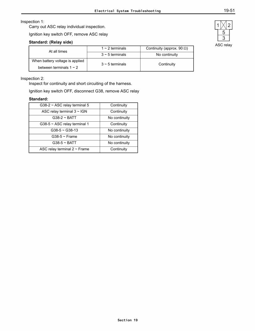
19-51
Inspection 1: Carry out ASC relay individual inspection.
Ignition key switch OFF, remove ASC relay
Standard: (Relay side)
Inspection 2: Inspect for continuity and short circuiting of the harness.
Ignition key switch OFF, disconnect G38, remove ASC relay
Standard:
At all times1 ~ 2 terminals Continuity (approx. 90 Ω)
3 ~ 5 terminals No continuity
When battery voltage is applied
between terminals 1 ~ 23 ~ 5 terminals Continuity
G38-2 ~ ASC relay terminal 5 Continuity
ASC relay terminal 3 ~ IGN Continuity
G38-2 ~ BATT No continuity
G38-5 ~ ASC relay terminal 1 Continuity
G38-5 ~ G38-13 No continuity
G38-5 ~ Frame No continuity
G38-5 ~ BATT No continuity
ASC relay terminal 2 ~ Frame Continuity
ASC relay
Electrical System Troubleshooting
Section 19

19-5219-52
Error codes 15-1 and 15-2 (NMR switch abnormality)Related portion
Probable cause Connector contact defect NMR switch defect Harness defect ASC controller defect Mechanical system defect (link catching, switch position adjustment, step motor defect etc.)
RE
CTA
B
G39
12 (NMR)
G3621
ASC controller
IGN
NMR switch
Starting motor relay2 (STA) 1
R/B Starting motor relayAG2
3
Electrical System Troubleshooting
Section 19
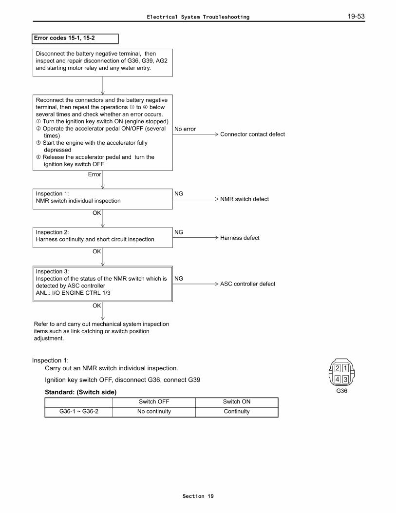
19-53
Inspection 1: Carry out an NMR switch individual inspection.
Ignition key switch OFF, disconnect G36, connect G39
Standard: (Switch side)
Error codes 15-1, 15-2
Switch OFF Switch ON
G36-1 ~ G36-2 No continuity Continuity
Reconnect the connectors and the battery negative terminal, then repeat the operations to below several times and check whether an error occurs.
Turn the ignition key switch ON (engine stopped) Operate the accelerator pedal ON/OFF (several
times) Start the engine with the accelerator fully
depressed Release the accelerator pedal and turn the
ignition key switch OFF
No errorConnector contact defect
NGInspection 1:NMR switch individual inspection NMR switch defect
OK
NGInspection 2:Harness continuity and short circuit inspection Harness defect
OK
NGASC controller defect
Inspection 3:Inspection of the status of the NMR switch which is detected by ASC controllerANL.: I/O ENGINE CTRL 1/3
OK
Refer to and carry out mechanical system inspection items such as link catching or switch position adjustment.
Error
Disconnect the battery negative terminal, then inspect and repair disconnection of G36, G39, AG2 and starting motor relay and any water entry.
G36
Electrical System Troubleshooting
Section 19

19-5419-54
Inspection 2: Inspect for continuity and short circuiting of the harness.
Ignition key switch OFF, disconnect G36, G39 and starting motor relay
Standard:
Inspection 3: Carry out inspection of the status of the NMR switch in the controller.
Ignition key switch OFF, remove NMR switch so that it can be turned ON and OFF manually,connect G39 and G36, ignition key switch ONNMR switch (I/O monitor: NMR)
Standard:
G39-12 ~ G36-1 Continuity
IGN ~ G36-2 Continuity
G39-2 ~ Starting motor relay terminal 1 Continuity
G39-12 ~ IGN No continuity
Analyzer display Switch OFF Switch ON
NMR 0 1
Electrical System Troubleshooting
Section 19

19-55
Error code 15-3 (NMR switch abnormality)Related portion
Probable cause Connector contact defect NMR switch defect Idle switch defect Harness defect ASC controller defect Mechanical system defect (link catching, switch position adjustment, step motor defect etc.)
IGN
G39
12 (NMR)
ASC controller
15 (ZERO)
G36
12
NMR switch
Idle switch34
Electrical System Troubleshooting
Section 19

19-5619-56
Inspection 1: Carry out an NMR and idle switch individual inspection.
Ignition key switch OFF, disconnect G36, connect G39
Standard: (Switch side)
Inspection 2: Inspect for continuity and short circuiting of the harness.
Ignition key switch OFF, disconnect G36 and G39
Standard:
Error code 15-3
Switch OFF Switch ON
G36-1 ~ G36-2 No continuity Continuity
G36-3 ~ G36-4 No continuity Continuity
G39-12 ~ IG No continuity
G39-15 ~ IG No continuity
Reconnect the connectors and the battery negative terminal, then repeat the operations to below several times and check whether an error occurs.
Turn the ignition key switch ON (engine stopped) Operate the accelerator pedal ON/OFF (several
times) Turn the ignition key switch OFF
No errorConnector contact defect
NGInspection 1:NMR and idle switch individual inspection
NMR switch defectIdle switch defect
OK
NGInspection 2:Carry out harness continuity and short circuit inspection
Harness defect
OK
NGASC controller defect
Inspection 3:Inspection of the status of the NMR and idle switches in the controllerANL.: I/O ENGINE CTRL 1/3
OK
Refer to and carry out mechanical system inspection items such as link catching or switch position adjustment.
Error
Disconnect the battery negative terminal, then inspect and repair disconnection of G39 and G36 and any water entry.
G36
Electrical System Troubleshooting
Section 19
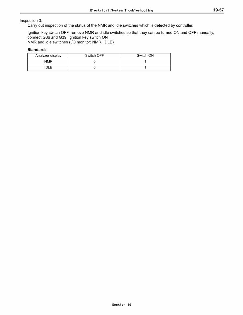
19-57
Inspection 3: Carry out inspection of the status of the NMR and idle switches which is detected by controller.
Ignition key switch OFF, remove NMR and idle switches so that they can be turned ON and OFF manually,connect G36 and G39, ignition key switch ONNMR and idle switches (I/O monitor: NMR, IDLE)
Standard:Analyzer display Switch OFF Switch ON
NMR 0 1
IDLE 0 1
Electrical System Troubleshooting
Section 19

19-5819-58
Error codes 16-1 and 16-2 (Idle switch abnormality)Related portion
Probable cause Connector contact defect Idle switch defect Harness defect ASC controller defect Mechanical system defect (link catching, switch position adjustment, step motor defect etc.)
Note:In the case where a 13-1 error is present, service that error first before dealing with this one.
IGN
G39
15 (ZERO)
ASC controllerG37
11 (NINA)12 (NINB)3 (INA)4 (INB)
G36
34
Idle switch
Step motor
2 (NIA)1 (NIB)5 (IA)4 (IB)
G38
Electrical System Troubleshooting
Section 19
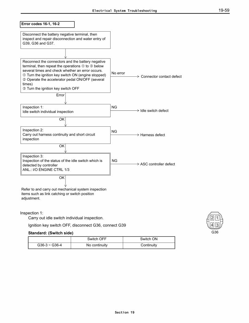
19-59
Inspection 1: Carry out idle switch individual inspection.
Ignition key switch OFF, disconnect G36, connect G39
Standard: (Switch side)
Error codes 16-1, 16-2
Switch OFF Switch ON
G36-3 ~ G36-4 No continuity Continuity
Reconnect the connectors and the battery negative terminal, then repeat the operations to below several times and check whether an error occurs.
Turn the ignition key switch ON (engine stopped) Operate the accelerator pedal ON/OFF (several
times) Turn the ignition key switch OFF
No error
NGInspection 1:Idle switch individual inspection Idle switch defect
OK
NGInspection 2:Carry out harness continuity and short circuit inspection
Harness defect
OK
NGASC controller defect
Inspection 3:Inspection of the status of the idle switch which is detected by controllerANL.: I/O ENGINE CTRL 1/3
OK
Refer to and carry out mechanical system inspection items such as link catching or switch position adjustment.
Error
Disconnect the battery negative terminal, then inspect and repair disconnection and water entry of G39, G36 and G37.
Connector contact defect
G36
Electrical System Troubleshooting
Section 19

19-6019-60
Inspection 2: Inspect for continuity and short circuiting of the harness.
Ignition key switch OFF, disconnect G36, G37, G38 and G39
Standard:
Inspection 3: Carry out inspection of the status of the idle switch which is detected by controller.
Ignition key switch OFF, remove idle switch so that it can be turned ON and OFF manually, connect G36 andG39, ignition key switch ONIdle switch (I/O monitor: IDLE)
Standard:
G39-15 ~ G36-3 Continuity
IGN ~ G36-4 Continuity
G39-15 ~ IGN No continuity
G38-11 ~ G37-2 Continuity
G38-12 ~ G37-1 Continuity
G38-3 ~ G37-5 Continuity
G38-4 ~ G37-4 Continuity
G38-11 ~G38-12 No continuity
G38-11 ~ G38-3 No continuity
G38-11 ~ G38-4 No continuity
G38-12 ~ G38-3 No continuity
G38-12 ~ G38-4 No continuity
G38-3 ~ G38-4 No continuity
G38-11 ~ IGN No continuity
G38-12 ~ IGN No continuity
G38-3 ~ IGN No continuity
G38-4 ~ IGN No continuity
G38-11 ~ Frame No continuity
G38-12 ~ Frame No continuity
G38-3 ~ Frame No continuity
G38-4 ~ Frame No continuity
Analyzer display Switch OFF Switch ON
IDLE 0 1
Electrical System Troubleshooting
Section 19
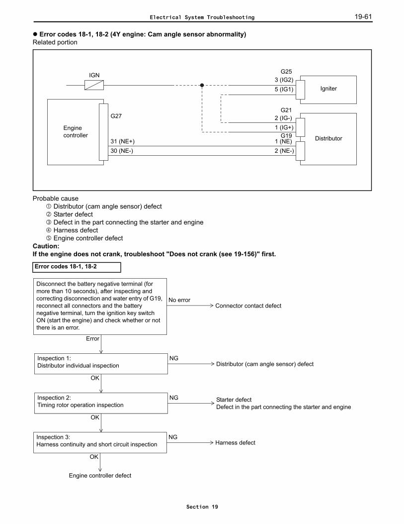
19-61
Error codes 18-1, 18-2 (4Y engine: Cam angle sensor abnormality)Related portion
Probable cause Distributor (cam angle sensor) defect Starter defect Defect in the part connecting the starter and engine Harness defect Engine controller defect
Caution:If the engine does not crank, troubleshoot "Does not crank (see 19-156)" first.
Error codes 18-1, 18-2
Engine controller
Igniter
Distributor
IGN
G27
G25
31 (NE+)30 (NE-)
3 (IG2)5 (IG1)
2 (IG-)1 (IG+)
G21
G191 (NE)2 (NE-)
NGInspection 1:Distributor individual inspection Distributor (cam angle sensor) defect
OK
NGInspection 2:Timing rotor operation inspection
Starter defectDefect in the part connecting the starter and engine
OK
Engine controller defect
Error
NGInspection 3:Harness continuity and short circuit inspection Harness defect
OK
No error
Disconnect the battery negative terminal (for more than 10 seconds), after inspecting and correcting disconnection and water entry of G19, reconnect all connectors and the battery negative terminal, turn the ignition key switch ON (start the engine) and check whether or not there is an error.
Connector contact defect
Electrical System Troubleshooting
Section 19
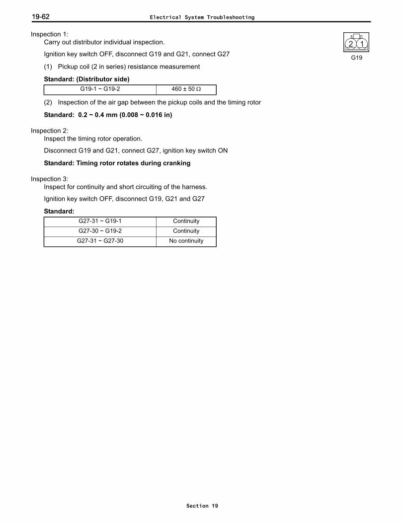
19-6219-62
Inspection 1: Carry out distributor individual inspection.
Ignition key switch OFF, disconnect G19 and G21, connect G27
(1) Pickup coil (2 in series) resistance measurement
Standard: (Distributor side)
(2) Inspection of the air gap between the pickup coils and the timing rotor
Standard: 0.2 ~ 0.4 mm (0.008 ~ 0.016 in)
Inspection 2: Inspect the timing rotor operation.
Disconnect G19 and G21, connect G27, ignition key switch ON
Standard: Timing rotor rotates during cranking
Inspection 3: Inspect for continuity and short circuiting of the harness.
Ignition key switch OFF, disconnect G19, G21 and G27
Standard:
G19-1 ~ G19-2 460 ± 50 Ω
12
G19
G27-31 ~ G19-1 Continuity
G27-30 ~ G19-2 Continuity
G27-31 ~ G27-30 No continuity
Electrical System Troubleshooting
Section 19

19-63
Error code 18-3 (4Y engine: Crank angle sensor abnormality)Related portion
Probable cause Crank angle sensor defect Harness defect Engine controller defect
Error code 18-3
Engine controller
Crank anglesensor
G2711 (G2) 1 (G2)22 (G-) 2 (G-)
G18
NGInspection 1:Harness continuity and short circuit inspection Harness defect
OK
NGInspection 2:Crank angle sensor individual inspection Crank angle sensor defect
OK
Engine controller defect
No error Normal(Entry of foreign matter etc.)
Error
Inspection 3:Crank angle sensor installation inspection
Install the crank angle sensor, connect G27, G18 and battery negative terminal, start the engine.Check whether an error occurs.
Error
No error
Disconnect the battery negative terminal (for more than 10 seconds), after inspecting and correcting disconnection and water entry of G18, reconnect all connectors and the battery negative terminal, turn the ignition key switch ON (start the engine) and check whether or not there is an error.
Connector contact defect
Electrical System Troubleshooting
Section 19
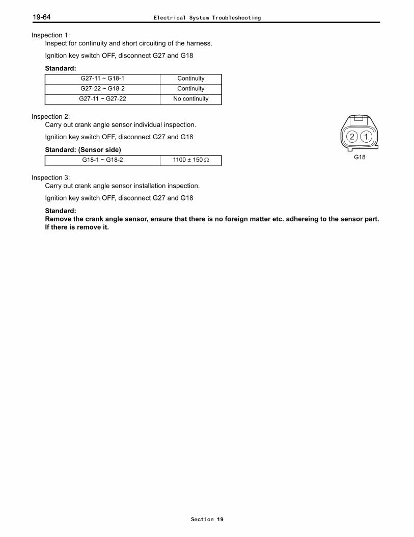
19-6419-64
Inspection 1: Inspect for continuity and short circuiting of the harness.
Ignition key switch OFF, disconnect G27 and G18
Standard:
Inspection 2: Carry out crank angle sensor individual inspection.
Ignition key switch OFF, disconnect G27 and G18
Standard: (Sensor side)
Inspection 3: Carry out crank angle sensor installation inspection.
Ignition key switch OFF, disconnect G27 and G18
Standard:Remove the crank angle sensor, ensure that there is no foreign matter etc. adhereing to the sensor part.If there is remove it.
G27-11 ~ G18-1 Continuity
G27-22 ~ G18-2 Continuity
G27-11 ~ G27-22 No continuity
G18-1 ~ G18-2 1100 ± 150 Ω
12
G18
Electrical System Troubleshooting
Section 19
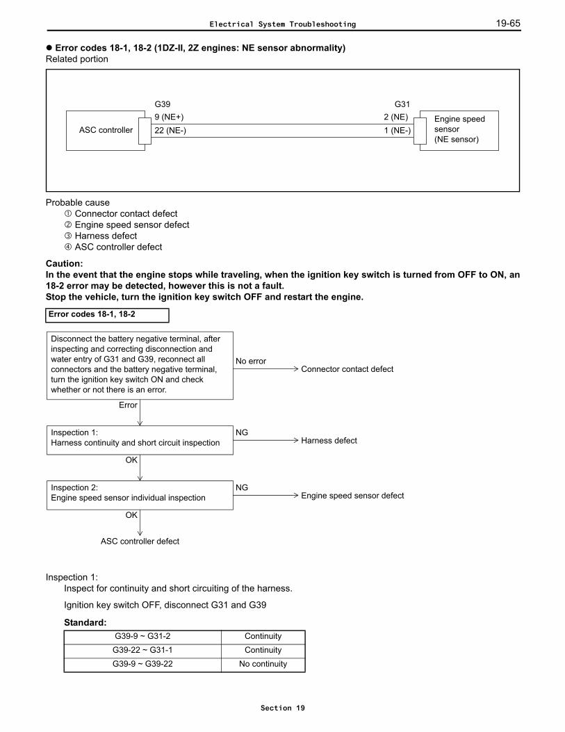
19-65
Error codes 18-1, 18-2 (1DZ-II, 2Z engines: NE sensor abnormality)Related portion
Probable cause Connector contact defect Engine speed sensor defect Harness defect ASC controller defect
Caution:In the event that the engine stops while traveling, when the ignition key switch is turned from OFF to ON, an18-2 error may be detected, however this is not a fault.Stop the vehicle, turn the ignition key switch OFF and restart the engine.
Inspection 1: Inspect for continuity and short circuiting of the harness.
Ignition key switch OFF, disconnect G31 and G39
Standard:
Error codes 18-1, 18-2
G39-9 ~ G31-2 Continuity
G39-22 ~ G31-1 Continuity
G39-9 ~ G39-22 No continuity
ASC controllerEngine speedsensor (NE sensor)
G399 (NE+) 2 (NE)22 (NE-) 1 (NE-)
G31
NGInspection 1:Harness continuity and short circuit inspection Harness defect
OK
NGInspection 2:Engine speed sensor individual inspection Engine speed sensor defect
OK
Error
ASC controller defect
No error
Disconnect the battery negative terminal, after inspecting and correcting disconnection and water entry of G31 and G39, reconnect all connectors and the battery negative terminal, turn the ignition key switch ON and check whether or not there is an error.
Connector contact defect
Electrical System Troubleshooting
Section 19
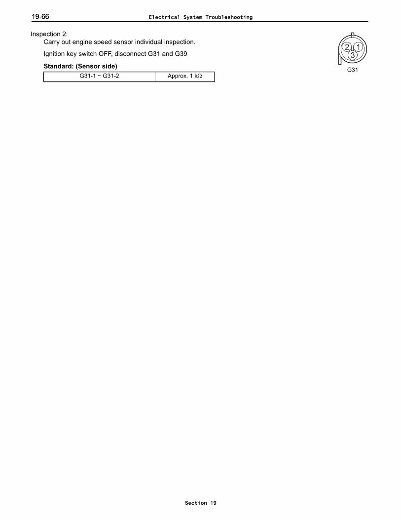
19-6619-66
Inspection 2: Carry out engine speed sensor individual inspection.
Ignition key switch OFF, disconnect G31 and G39
Standard: (Sensor side)G31-1 ~ G31-2 Approx. 1 kΩ
2 13
G31
Electrical System Troubleshooting
Section 19

19-67
Error codes 1F-1, 1F-2, 1F-3, 1F-4, 1F-5, 1F-6, 1F-7, 1F-8 (CPU abnormality)Related portion
Probable cause ASC controller defect
ASC controller
Electrical System Troubleshooting
Section 19
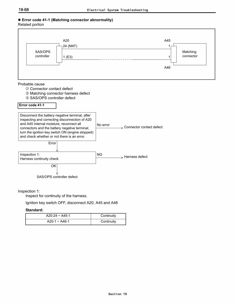
19-6819-68
Error code 41-1 (Matching connector abnormality)Related portion
Probable cause Connector contact defect Matching connector harness defect SAS/OPS controller defect
Inspection 1: Inspect for continuity of the harness.
Ignition key switch OFF, disconnect A20, A45 and A46
Standard:
Error code 41-1
A20-24 ~ A45-1 Continuity
A20-1 ~ A46-1 Continuity
SAS/OPS controller
Matchingconnector
A2024 (MAT)
1 (E3)
1
1
A45
A46
NG
OK
Inspection 1:Harness continuity check Harness defect
SAS/OPS controller defect
Error
No error
Disconnect the battery negative terminal, after inspecting and correcting disconnection of A20 and A45 internal moisture, reconnect all connectors and the battery negative terminal, turn the ignition key switch ON (engine stopped) and check whether or not there is an error.
Connector contact defect
Electrical System Troubleshooting
Section 19

19-69
Error codes 51-1, 51-2 (Speed sensor abnormality)Related portion
Probable cause Connector contact defect Harness defect Speed sensor defect SAS/OPS controller defect
Inspection 1: Ignition key switch OFF, disconnect A19, use SST 09236-13900-71 to short circuit A19, ignition key switch ON,engine stopped
51-1 displayed → to inspection 2No error displayed → Speed sensor error
Error code 51-1
SAS/OPScontroller
Speedsensor
A2122 (SP1+)23 (SP1-)
12
A19
Speed sensor defectInspection 1:Speed sensor inspection
Error
No error
Harness defectInspection 2:Harness continuity and short circuit inspection
OK
NG
SAS/OPS controller defect
Error
No error
Disconnect the battery negative terminal, after inspecting and correcting disconnection and water entry of A19 and A21, reconnect all connectors and the battery negative terminal, turn the ignition key switch ON (engine stopped) and check whether or not there is an error.
Connector contact defect
Electrical System Troubleshooting
Section 19

19-7019-70
Inspection 2: Inspect for continuity and short circuiting of the harness.
Ignition key switch OFF, disconnect A19 and A21
Standard:
Inspection 1: Ignition key switch OFF, disconnect A19, ignition key switch ON, engine stopped
51-2 displayed → to next inspection51-1 displayed → Speed sensor defect
Inspection 2: Inspect for continuity and short circuiting of the harness.
Ignition key switch OFF, disconnect A19 and A21
Standard:
A21-22 ~ A19-1 Continuity
A21-23 ~ A19-2 Continuity
A21-22 ~ Frame No continuity
A21-23 ~ Frame No continuity
Error code 51-2
A21-22 ~ A19-1 Continuity
A21-23 ~ A19-2 Continuity
A21-22 ~ Frame No continuity
A21-23 ~ Frame No continuity
Sensor defectInspection 1:Speed sensor inspection
51-2 is displayed
51-1 is displayed
OK
SAS/OPS controller defect
NGInspection 2:Harness continuity and short circuit inspection
Error
No error
Disconnect the battery negative terminal, after inspecting and correcting disconnection of A19 and A21 and internal moisture, reconnect all connectors and the battery negative terminal, turn the ignition key switch ON (engine stopped) and check whether or not there is an error.
Connector contact defect
Harness defect
Electrical System Troubleshooting
Section 19
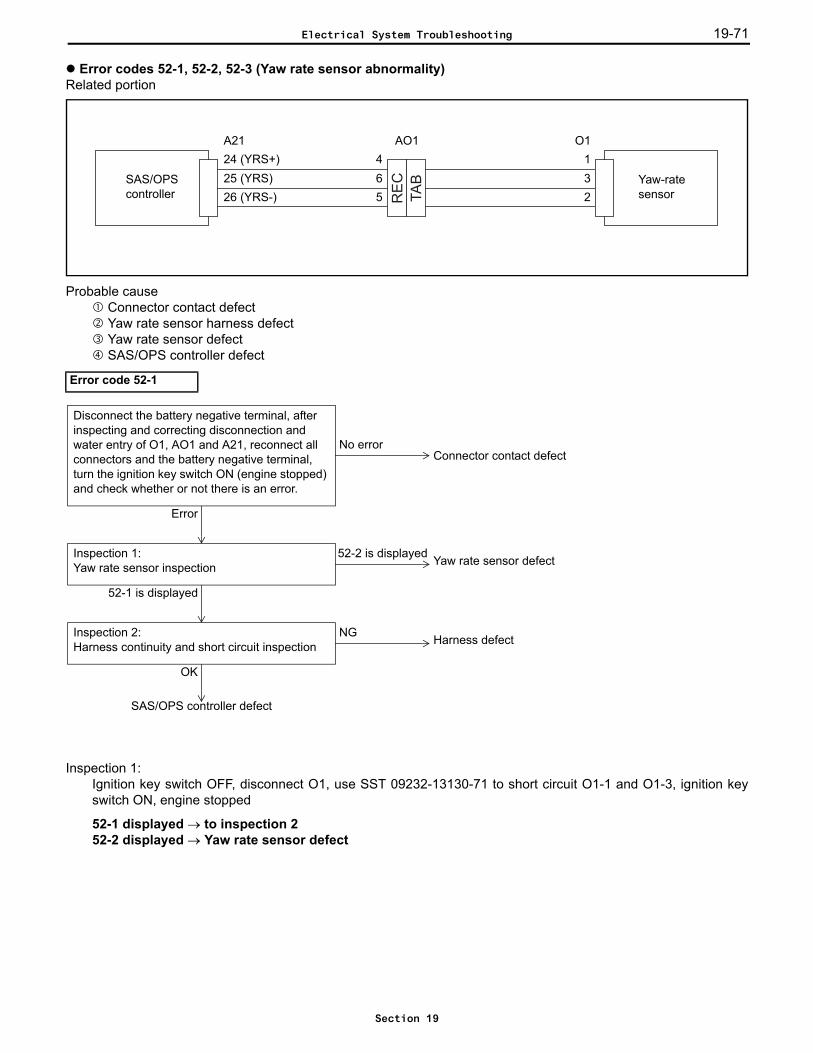
19-71
Error codes 52-1, 52-2, 52-3 (Yaw rate sensor abnormality)Related portion
Probable cause Connector contact defect Yaw rate sensor harness defect Yaw rate sensor defect SAS/OPS controller defect
Inspection 1: Ignition key switch OFF, disconnect O1, use SST 09232-13130-71 to short circuit O1-1 and O1-3, ignition keyswitch ON, engine stopped
52-1 displayed → to inspection 252-2 displayed → Yaw rate sensor defect
Error code 52-1
TA
B
RE
C
26 (YRS-)SAS/OPScontroller
Yaw-ratesensor
A2124 (YRS+)25 (YRS)
1O1
32
465
AO1
Yaw rate sensor defectInspection 1:Yaw rate sensor inspection
52-1 is displayed
52-2 is displayed
Harness defectInspection 2:Harness continuity and short circuit inspection
OK
NG
SAS/OPS controller defect
Error
No error
Disconnect the battery negative terminal, after inspecting and correcting disconnection and water entry of O1, AO1 and A21, reconnect all connectors and the battery negative terminal, turn the ignition key switch ON (engine stopped) and check whether or not there is an error.
Connector contact defect
Electrical System Troubleshooting
Section 19
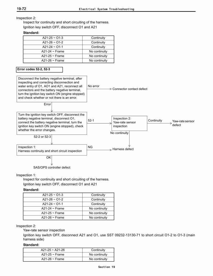
19-7219-72
Inspection 2: Inspect for continuity and short circuiting of the harness.Ignition key switch OFF, disconnect O1 and A21Standard:
Inspection 1: Inspect for continuity and short circuiting of the harness.Ignition key switch OFF, disconnect O1 and A21Standard:
Inspection 2: Yaw-rate sensor inspectionIgnition key switch OFF, disconnect A21 and O1, use SST 09232-13130-71 to short circuit O1-2 to O1-3 (mainharness side)Standard:
A21-25 ~ O1-3 ContinuityA21-26 ~ O1-2 ContinuityA21-24 ~ O1-1 Continuity
A21-24 ~ Frame No continuityA21-25 ~ Frame No continuityA21-26 ~ Frame No continuity
Error codes 52-2, 52-3
A21-25 ~ O1-3 ContinuityA21-26 ~ O1-2 ContinuityA21-24 ~ O1-1 Continuity
A21-24 ~ Frame No continuityA21-25 ~ Frame No continuityA21-26 ~ Frame No continuity
A21-25 ~ A21-26 ContinuityA21-25 ~ Frame No continuityA21-26 ~ Frame No continuity
Harness defectInspection 1:Harness continuity and short circuit inspection
OK
NG
SAS/OPS controller defect
Turn the ignition key switch OFF, disconnect the battery negative terminal, disconnect O1, connect the battery negative terminal, turn the ignition key switch ON (engine stopped), check whether the error changes.
52-2 or 52-3
Error
No error
Disconnect the battery negative terminal, after inspecting and correcting disconnection and water entry of O1, AO1 and A21, reconnect all connectors and the battery negative terminal, turn the ignition key switch ON (engine stopped) and check whether or not there is an error.
Connector contact defect
Inspection 2:Yaw-rate sensor inspection
Yaw-rate sensor defect
Continuity
No continuity
52-1
Electrical System Troubleshooting
Section 19
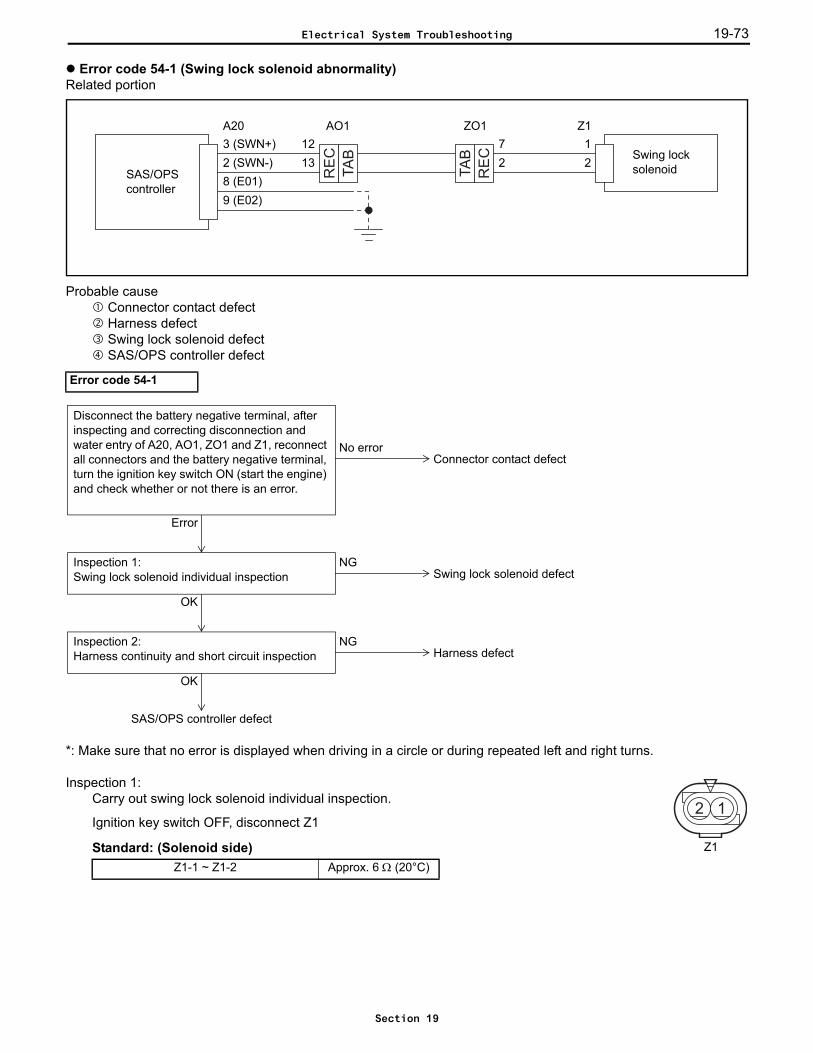
19-73
Error code 54-1 (Swing lock solenoid abnormality)Related portion
Probable cause Connector contact defect Harness defect Swing lock solenoid defect SAS/OPS controller defect
*: Make sure that no error is displayed when driving in a circle or during repeated left and right turns.
Inspection 1: Carry out swing lock solenoid individual inspection.
Ignition key switch OFF, disconnect Z1
Standard: (Solenoid side)
Error code 54-1
Z1-1 ~ Z1-2 Approx. 6 Ω (20°C)
TA
B
RE
C
RE
C
TA
B
SAS/OPS controller
Swing lock solenoid
A20
8 (E01)
1
9 (E02)
22 (SWN-)3 (SWN+)
Z172
ZO11213
AO1
NGInspection 1:Swing lock solenoid individual inspection
OK
NGInspection 2:Harness continuity and short circuit inspection
OK
SAS/OPS controller defect
Swing lock solenoid defect
Harness defect
Error
No error
Disconnect the battery negative terminal, after inspecting and correcting disconnection and water entry of A20, AO1, ZO1 and Z1, reconnect all connectors and the battery negative terminal, turn the ignition key switch ON (start the engine) and check whether or not there is an error.
Connector contact defect
2 1
Z1
Electrical System Troubleshooting
Section 19
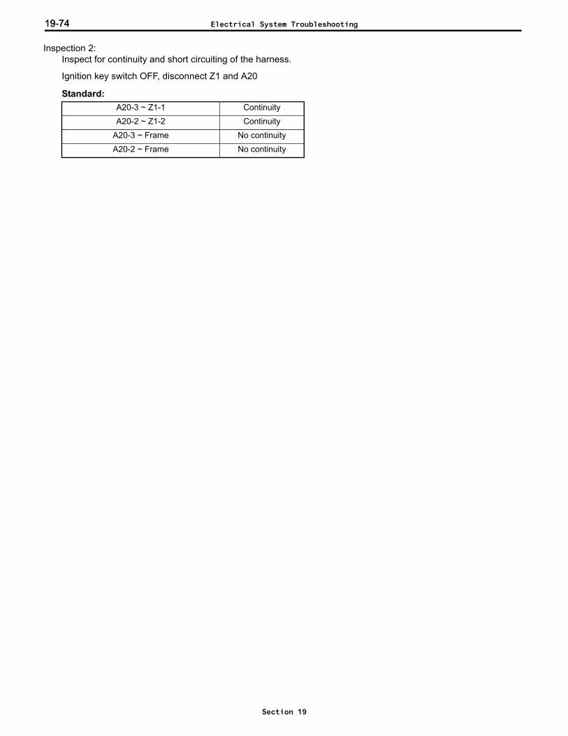
19-7419-74
Inspection 2: Inspect for continuity and short circuiting of the harness.
Ignition key switch OFF, disconnect Z1 and A20
Standard:A20-3 ~ Z1-1 Continuity
A20-2 ~ Z1-2 Continuity
A20-3 ~ Frame No continuity
A20-2 ~ Frame No continuity
Electrical System Troubleshooting
Section 19
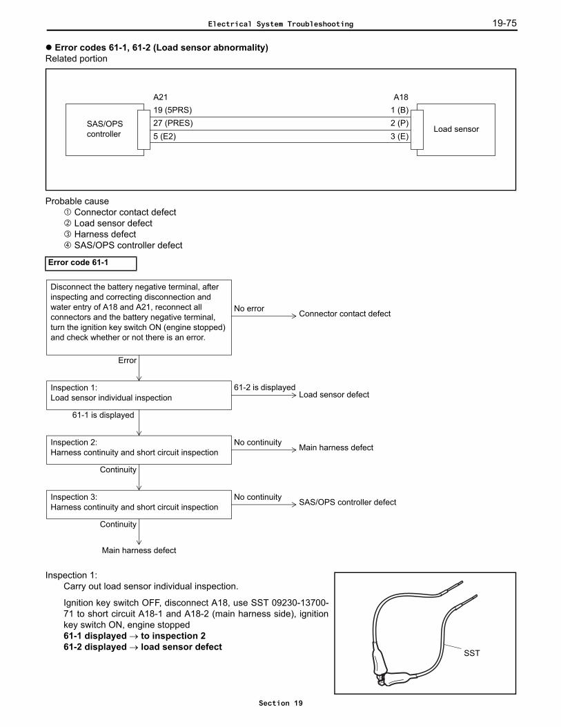
19-75
Error codes 61-1, 61-2 (Load sensor abnormality)Related portion
Probable cause Connector contact defect Load sensor defect Harness defect SAS/OPS controller defect
Inspection 1: Carry out load sensor individual inspection.
Ignition key switch OFF, disconnect A18, use SST 09230-13700-71 to short circuit A18-1 and A18-2 (main harness side), ignitionkey switch ON, engine stopped61-1 displayed → to inspection 261-2 displayed → load sensor defect
Error code 61-1
5 (E2)SAS/OPS controller Load sensor
A2119 (5PRS)27 (PRES)
1 (B)A18
2 (P)3 (E)
No continuityInspection 2:Harness continuity and short circuit inspection
Continuity
61-2 is displayedInspection 1:Load sensor individual inspection
61-1 is displayed
Main harness defect
Main harness defect
Load sensor defect
No continuityInspection 3:Harness continuity and short circuit inspection
Continuity
SAS/OPS controller defect
Error
No error
Disconnect the battery negative terminal, after inspecting and correcting disconnection and water entry of A18 and A21, reconnect all connectors and the battery negative terminal, turn the ignition key switch ON (engine stopped) and check whether or not there is an error.
Connector contact defect
SST
Electrical System Troubleshooting
Section 19
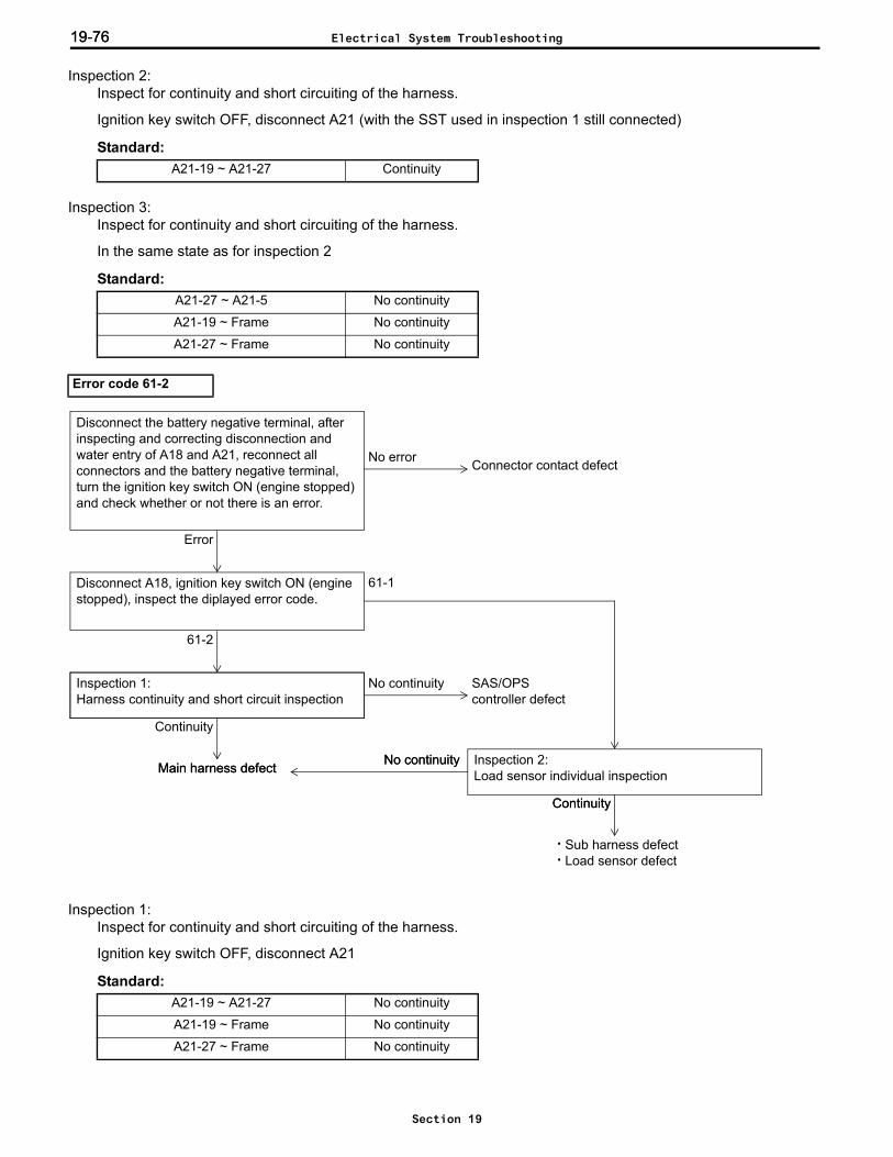
19-7619-76
Inspection 2: Inspect for continuity and short circuiting of the harness.
Ignition key switch OFF, disconnect A21 (with the SST used in inspection 1 still connected)
Standard:
Inspection 3: Inspect for continuity and short circuiting of the harness.
In the same state as for inspection 2
Standard:
Inspection 1: Inspect for continuity and short circuiting of the harness.
Ignition key switch OFF, disconnect A21
Standard:
A21-19 ~ A21-27 Continuity
A21-27 ~ A21-5 No continuity
A21-19 ~ Frame No continuity
A21-27 ~ Frame No continuity
Error code 61-2
A21-19 ~ A21-27 No continuity
A21-19 ~ Frame No continuity
A21-27 ~ Frame No continuity
Disconnect A18, ignition key switch ON (engine stopped), inspect the diplayed error code.
61-2
No continuityInspection 1:Harness continuity and short circuit inspection
Continuity
61-1
Main harness defect
SAS/OPScontroller defect
· Sub harness defect· Load sensor defect
Inspection 2:Load sensor individual inspection
Continuity
No continuityMain harness defect
Continuity
No continuity
Error
No error
Disconnect the battery negative terminal, after inspecting and correcting disconnection and water entry of A18 and A21, reconnect all connectors and the battery negative terminal, turn the ignition key switch ON (engine stopped) and check whether or not there is an error.
Connector contact defect
Electrical System Troubleshooting
Section 19
19-77
Inspection 2: Carry out load sensor individual inspection.
Ignition key switch OFF, disconnect the battery negative terminal, disconnect A18 and A21, use SST 09230-13700-71 to short circuit A18-2 to A18-3 (main harness side)
Standard:A21-27 ~ A21-5 Continuity
Electrical System Troubleshooting
Section 19
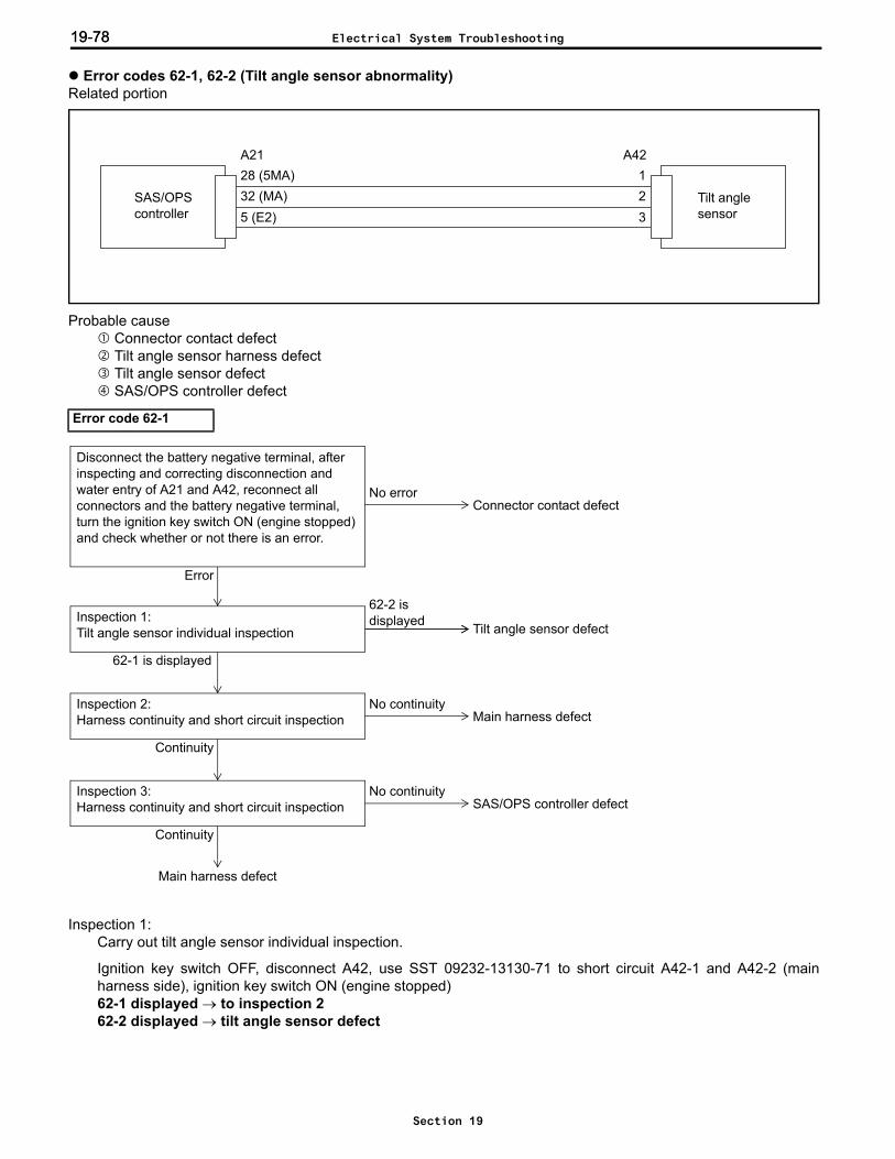
19-7819-78
Error codes 62-1, 62-2 (Tilt angle sensor abnormality)Related portion
Probable cause Connector contact defect Tilt angle sensor harness defect Tilt angle sensor defect SAS/OPS controller defect
Inspection 1: Carry out tilt angle sensor individual inspection.
Ignition key switch OFF, disconnect A42, use SST 09232-13130-71 to short circuit A42-1 and A42-2 (mainharness side), ignition key switch ON (engine stopped)62-1 displayed → to inspection 262-2 displayed → tilt angle sensor defect
Error code 62-1
5 (E2)SAS/OPS controller
Tilt angle sensor
A2128 (5MA)32 (MA)
1A42
23
No continuityInspection 2:Harness continuity and short circuit inspection
Continuity
Inspection 1:Tilt angle sensor individual inspection
62-1 is displayed
Main harness defect
Main harness defect
Tilt angle sensor defect
No continuityInspection 3:Harness continuity and short circuit inspection
Continuity
SAS/OPS controller defect
Error
No error
Disconnect the battery negative terminal, after inspecting and correcting disconnection and water entry of A21 and A42, reconnect all connectors and the battery negative terminal, turn the ignition key switch ON (engine stopped) and check whether or not there is an error.
Connector contact defect
62-2 is displayed
Electrical System Troubleshooting
Section 19
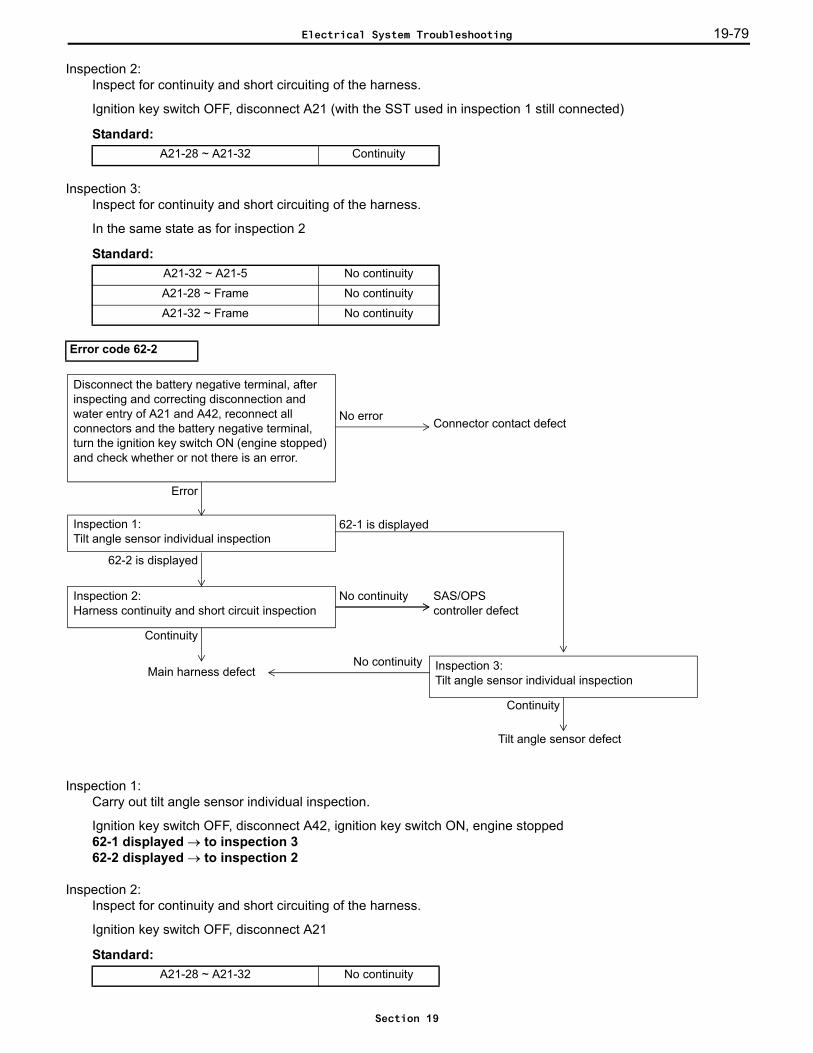
19-79
Inspection 2: Inspect for continuity and short circuiting of the harness.
Ignition key switch OFF, disconnect A21 (with the SST used in inspection 1 still connected)
Standard:
Inspection 3: Inspect for continuity and short circuiting of the harness.
In the same state as for inspection 2
Standard:
Inspection 1: Carry out tilt angle sensor individual inspection.
Ignition key switch OFF, disconnect A42, ignition key switch ON, engine stopped62-1 displayed → to inspection 362-2 displayed → to inspection 2
Inspection 2: Inspect for continuity and short circuiting of the harness.
Ignition key switch OFF, disconnect A21
Standard:
A21-28 ~ A21-32 Continuity
A21-32 ~ A21-5 No continuity
A21-28 ~ Frame No continuity
A21-32 ~ Frame No continuity
Error code 62-2
A21-28 ~ A21-32 No continuity
No continuityInspection 2:Harness continuity and short circuit inspection
Continuity
62-1 is displayedInspection 1:Tilt angle sensor individual inspection
62-2 is displayed
Main harness defect
SAS/OPScontroller defect
Tilt angle sensor defect
Error
No error
Disconnect the battery negative terminal, after inspecting and correcting disconnection and water entry of A21 and A42, reconnect all connectors and the battery negative terminal, turn the ignition key switch ON (engine stopped) and check whether or not there is an error.
Connector contact defect
Inspection 3:Tilt angle sensor individual inspection
Continuity
No continuity
Electrical System Troubleshooting
Section 19

19-8019-80
Inspection 3: Carry out tilt angle sensor individual inspection.
Ignition key switch OFF, disconnect A21 and A42, use SST 09232-13130-71 to short circuit A21-2 and A42-3(main harness side)
Standard:A42-32 ~ A21-5 Continuity
Electrical System Troubleshooting
Section 19

19-81
Error codes 63-1, 63-2, 63-3 (Tilt lever switch abnormality)Related portion
Probable cause Connector contact defect Harness defect Forward tilt switch defect Tilt switch installation defect Backward tilt switch defect SAS/OPS controller defect
21 (MR)SAS/OPScontroller
Backward tiltswitch
A20
20 (MF)1 (E3)
1
A13
3
Forward tiltswitch
4
2
Electrical System Troubleshooting
Section 19
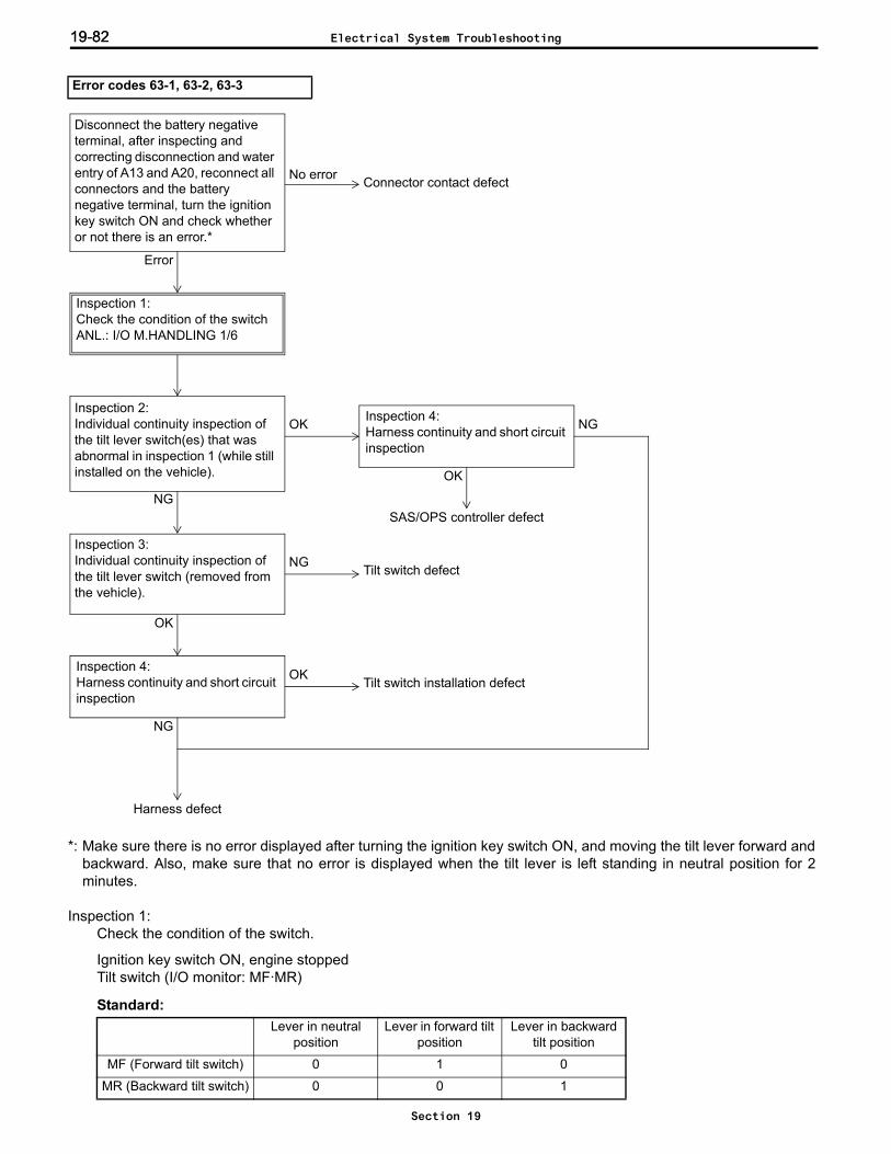
19-8219-82
*: Make sure there is no error displayed after turning the ignition key switch ON, and moving the tilt lever forward andbackward. Also, make sure that no error is displayed when the tilt lever is left standing in neutral position for 2minutes.
Inspection 1: Check the condition of the switch.
Ignition key switch ON, engine stoppedTilt switch (I/O monitor: MF·MR)
Standard:
Error codes 63-1, 63-2, 63-3
Lever in neutral position
Lever in forward tilt position
Lever in backward tilt position
MF (Forward tilt switch) 0 1 0
MR (Backward tilt switch) 0 0 1
OK
OKInspection 2:Individual continuity inspection of the tilt lever switch(es) that was abnormal in inspection 1 (while still installed on the vehicle).
NG
No error
Error
Connector contact defect
Tilt switch defect
Inspection 3:Individual continuity inspection of the tilt lever switch (removed from the vehicle).
OK
NG
Inspection 4:Harness continuity and short circuit inspection
OK
NG
Tilt switch installation defect
Harness defect
Inspection 4:Harness continuity and short circuit inspection
SAS/OPS controller defect
NG
Disconnect the battery negative terminal, after inspecting and correcting disconnection and water entry of A13 and A20, reconnect all connectors and the battery negative terminal, turn the ignition key switch ON and check whether or not there is an error.*
Inspection 1:Check the condition of the switchANL.: I/O M.HANDLING 1/6
Electrical System Troubleshooting
Section 19

19-83
Inspection 2: Individual continuity inspection of the tilt lever switch (still installed on the vehicle).
Ignition key switch OFF, disconnect A13
Standard: (Switch side)
Inspection 3: Carry out individual continuity inspection of the tilt lever switch (removed from the vehicle).
Ignition key switch OFF, disconnect A13
Standard: (Switch side)
Inspection 4: Inspect for continuity and short circuiting of the harness.
Ignition key switch OFF, disconnect A13 and A20
Standard:
Lever in neutral position
Lever in forward tilt position
Lever in backward tilt position
A13-1 ~ A13-2 No continuity Continuity No continuity
A13-3 ~ A13-4 No continuity No continuity Continuity
Switch OFF Switch ON
A13-1 ~ A13-2 No continuity Continuity
A13-3 ~ A13-4 No continuity No continuity
A20-20 ~ A20-1 No continuity
A20-21 ~ A20-1 No continuity
A20-20 ~ A20-21 No continuity
A20-20 ~ Frame No continuity
A20-21 ~ Frame No continuity
21
3 4
A13
Electrical System Troubleshooting
Section 19

19-8419-84
Error code 64-1 (Lift lock solenoid abnormality)Related portion
Probable cause Connector contact defect Harness defect Lift lock solenoid defect SAS/OPS controller defect
*: Make sure that no error is displayed when the material handling lever is lowered.
Inspection 1: Inspect for continuity and short circuiting of the harness.
Ignition key switch OFF, disconnect A11 and A20
Standard:
Error code 64-1
A20-7 ~ A11-1 Continuity
A11-2 ~ Frame Continuity
A20-9 ~ Frame Continuity
A20-8 ~ Frame Continuity
A20-7 ~ Frame No continuity
8 (E01)
Lift locksolenoid
A207 (LSOL)9 (E02)
A1112SAS/OPS
controller
NGInspection 1:Harness continuity and short circuit inspection
OK
Harness defect
NGInspection 2:Lift lock solenoid individual inspection
OK
Solenoid defect
SAS/OPS controller defect
Error
No error
Disconnect the battery negative terminal, after inspecting and correcting disconnection and water entry of A11 and A20, reconnect all connectors and the battery negative terminal, turn the ignition key switch ON (engine stopped) and check whether or not there is an error.*
Connector contact defect
Electrical System Troubleshooting
Section 19

19-85
Inspection 2: Carry out lift lock solenoid individual inspection.
Ignition key switch OFF, disconnect A11
Standard: (Solenoid side)A11-1 ~ A11-2 9.9 ± 0.5 Ω (20°C)
21
A11
Electrical System Troubleshooting
Section 19

19-8619-86
Error code 65-1 (Tilt control solenoid abnormality)Related portion
Probable cause Connector contact defect Harness defect Tilt control solenoid defect SAS/OPS controller defect
*: Make sure that no error is displayed when the material handling lever is operated to tilt forward.
Inspection 1: Inspect for continuity and short circuiting of the harness.
Ignition key switch OFF, disconnect A10 and A20
Standard:
Error code 65-1
A20-4 ~ A10-1 Continuity
A10-2 ~ Frame Continuity
A20-9 ~ Frame Continuity
A20-8 ~ Frame Continuity
A20-4 ~ Frame No continuity
8 (E01)
Tilt controlsolenoid
A204 (TSOL)9 (E02)
A1012SAS/OPS
controller
NGInspection 1:Harness continuity and short circuit inspection
OK
Harness defect
NGInspection 2:Tilt control solenoid individual inspection
OK
Solenoid defect
SAS/OPS controller defect
Error
No error
Disconnect the battery negative terminal, after inspecting and correcting disconnection and water entry of A10 and A20, reconnect all connectors and the battery negative terminal, turn the ignition key switch ON (engine stopped) and check whether or not there is an error.*
Connector contact defect
Electrical System Troubleshooting
Section 19

19-87
Inspection 2: Carry out tilt control solenoid individual inspection.
Ignition key switch OFF, disconnect A10
Standard: (Solenoid side)A10-1 ~ A10-2 9.9 ± 0.5 Ω (20°C)
21
A10
Electrical System Troubleshooting
Section 19
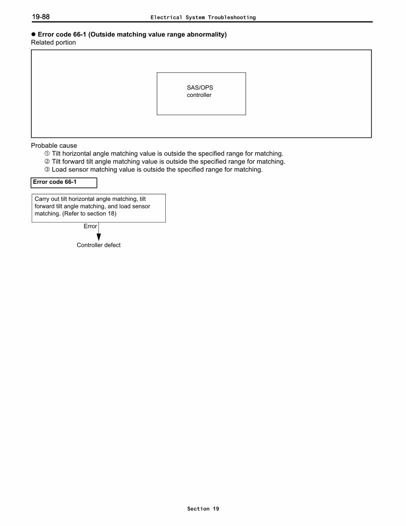
19-8819-88
Error code 66-1 (Outside matching value range abnormality)Related portion
Probable cause Tilt horizontal angle matching value is outside the specified range for matching. Tilt forward tilt angle matching value is outside the specified range for matching. Load sensor matching value is outside the specified range for matching.
Error code 66-1
SAS/OPScontroller
Error
Controller defect
Carry out tilt horizontal angle matching, tilt forward tilt angle matching, and load sensor matching. (Refer to section 18)
Electrical System Troubleshooting
Section 19
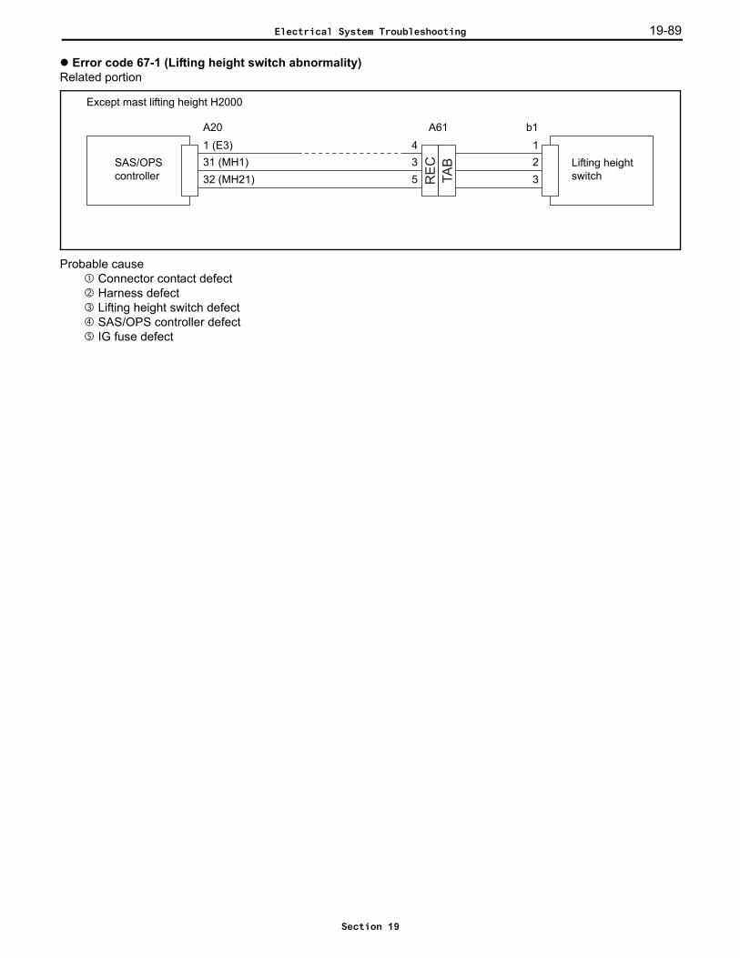
19-89
Error code 67-1 (Lifting height switch abnormality)Related portion
Probable cause Connector contact defect Harness defect Lifting height switch defect SAS/OPS controller defect IG fuse defect
TA
B
RE
C
A20 b1
Except mast lifting height H2000
11 (E3)31 (MH1)
3SAS/OPScontroller 32 (MH21)
Lifting height switch
2
A61435
Electrical System Troubleshooting
Section 19
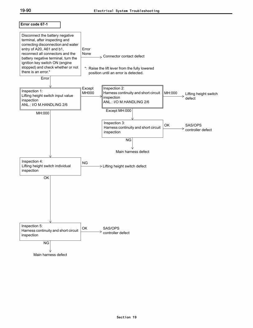
19-9019-90
Error code 67-1
Lifting height switch defect
MH:000
ErrorNone
Error
Connector contact defect
Disconnect the battery negative terminal, after inspecting and correcting disconnection and water entry of A20, A61 and b1, reconnect all connectors and the battery negative terminal, turn the ignition key switch ON (engine stopped) and check whether or not there is an error.*
Inspection 1:Lifting height switch input value inspectionANL.: I/O M.HANDLING 2/6
MH:000
Except MH000
Inspection 2:Harness continuity and short circuit inspectionANL.: I/O M.HANDLING 2/6
Except MH:000
OK SAS/OPScontroller defect
Inspection 3:Harness continuity and short circuit inspection
NG
Main harness defect
Inspection 4:Lifting height switch individual inspection
OK
Lifting height switch defectNG
Inspection 5:Harness continuity and short circuit inspection
NG
OK
Main harness defect
SAS/OPScontroller defect
*: Raise the lift lever from the fully lowered position until an error is detected.
Electrical System Troubleshooting
Section 19
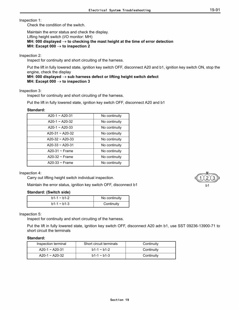
19-91
Inspection 1: Check the condition of the switch.
Maintain the error status and check the display.Lifting height switch (I/O monitor: MH)MH: 000 displayed → to checking the mast height at the time of error detectionMH: Except 000 → to inspection 2
Inspection 2: Inspect for continuity and short circuiting of the harness.
Put the lift in fully lowered state, ignition key switch OFF, disconnect A20 and b1, ignition key switch ON, stop theengine, check the displayMH: 000 displayed → sub harness defect or lifting height switch defectMH: Except 000 → to inspection 3
Inspection 3: Inspect for continuity and short circuiting of the harness.
Put the lift in fully lowered state, ignition key switch OFF, disconnect A20 and b1
Standard:
Inspection 4: Carry out lifting height switch individual inspection.
Maintain the error status, ignition key switch OFF, disconnect b1
Standard: (Switch side)
Inspection 5: Inspect for continuity and short circuiting of the harness.
Put the lift in fully lowered state, ignition key switch OFF, disconnect A20 adn b1, use SST 09236-13900-71 toshort circuit the terminals
Standard:
A20-1 ~ A20-31 No continuity
A20-1 ~ A20-32 No continuity
A20-1 ~ A20-33 No continuity
A20-31 ~ A20-32 No continuity
A20-32 ~ A20-33 No continuity
A20-33 ~ A20-31 No continuity
A20-31 ~ Frame No continuity
A20-32 ~ Frame No continuity
A20-33 ~ Frame No continuity
b1-1 ~ b1-2 No continuity
b1-1 ~ b1-3 Continuity
Inspection terminal Short circuit terminals Continuity
A20-1 ~ A20-31 b1-1 ~ b1-2 Continuity
A20-1 ~ A20-32 b1-1 ~ b1-3 Continuity
b1
1 2 3
Electrical System Troubleshooting
Section 19

19-9219-92
Error codes 68-1, 68-2, 68-3 (Lift switch abnormality)Related portion
Probable cause Connector contact defect Harness defect Raising lift switch defect Lift switch installation defect Lowering lift switch defect SAS/OPS controller defect
23 (MD)SAS/OPScontroller
Lowering lift switch
A20
22 (MU)1 (E3)
3
A14
1
Raising lift switch
2
4
Electrical System Troubleshooting
Section 19
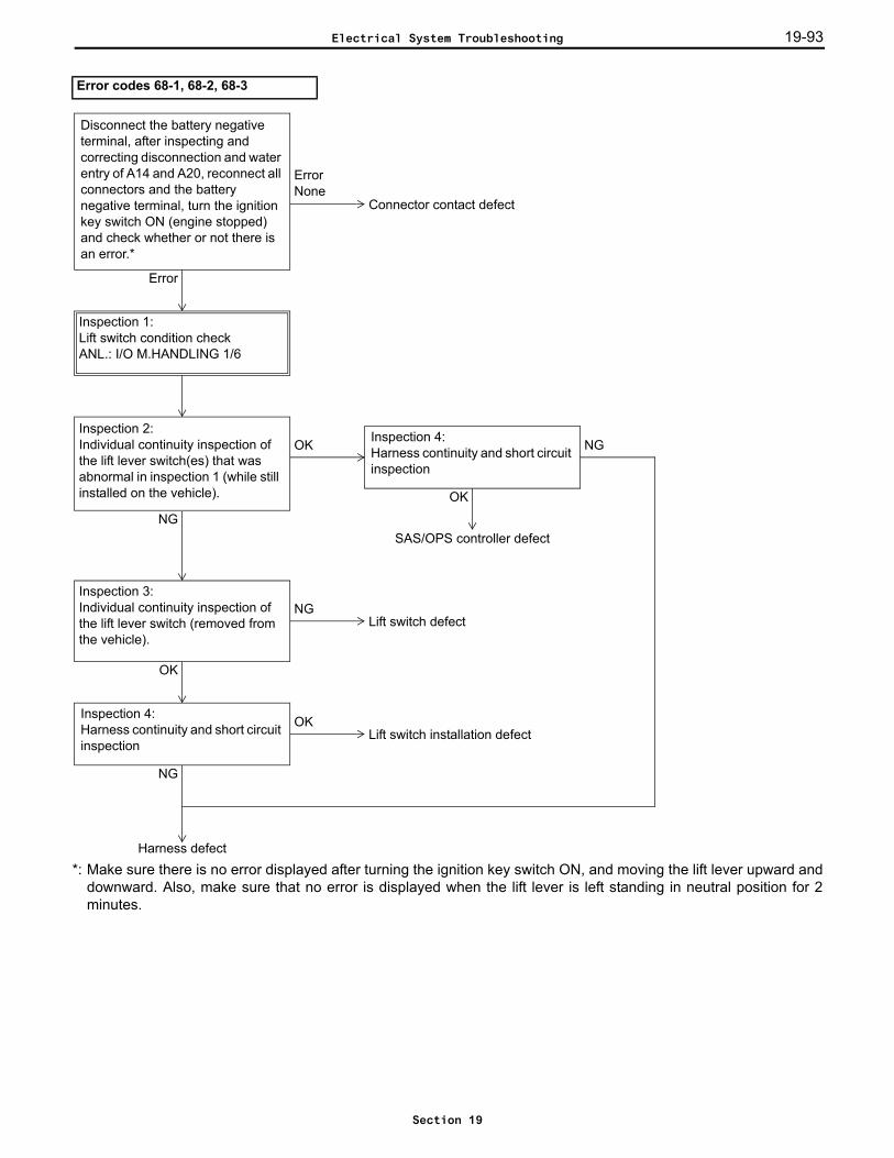
19-93
*: Make sure there is no error displayed after turning the ignition key switch ON, and moving the lift lever upward anddownward. Also, make sure that no error is displayed when the lift lever is left standing in neutral position for 2minutes.
Error codes 68-1, 68-2, 68-3
OK
OKInspection 2:Individual continuity inspection of the lift lever switch(es) that was abnormal in inspection 1 (while still installed on the vehicle).
NG
Inspection 1:Lift switch condition checkANL.: I/O M.HANDLING 1/6
Lift switch defect
Inspection 3:Individual continuity inspection of the lift lever switch (removed from the vehicle).
OK
NG
Inspection 4:Harness continuity and short circuit inspection
OK
NG
Lift switch installation defect
Harness defect
Inspection 4:Harness continuity and short circuit inspection
SAS/OPS controller defect
NG
ErrorNone
Error
Connector contact defect
Disconnect the battery negative terminal, after inspecting and correcting disconnection and water entry of A14 and A20, reconnect all connectors and the battery negative terminal, turn the ignition key switch ON (engine stopped) and check whether or not there is an error.*
Electrical System Troubleshooting
Section 19
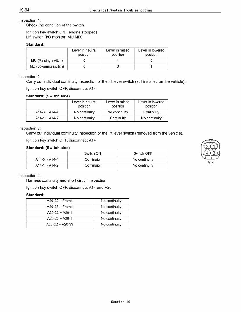
19-9419-94
Inspection 1: Check the condition of the switch.
Ignition key switch ON (engine stopped)Lift switch (I/O monitor: MU·MD)
Standard:
Inspection 2: Carry out individual continuity inspection of the lift lever switch (still installed on the vehicle).
Ignition key switch OFF, disconnect A14
Standard: (Switch side)
Inspection 3: Carry out individual continuity inspection of the lift lever switch (removed from the vehicle).
Ignition key switch OFF, disconnect A14
Standard: (Switch side)
Inspection 4: Harness continuity and short circuit inspection
Ignition key switch OFF, disconnect A14 and A20
Standard:
Lever in neutral position
Lever in raised position
Lever in lowered position
MU (Raising switch) 0 1 0
MD (Lowering switch) 0 0 1
Lever in neutral position
Lever in raised position
Lever in lowered position
A14-3 ~ A14-4 No continuity No continuity Continuity
A14-1 ~ A14-2 No continuity Continuity No continuity
Switch ON Switch OFF
A14-3 ~ A14-4 Continuity No continuity
A14-1 ~ A14-2 Continuity No continuity
A20-22 ~ Frame No continuity
A20-23 ~ Frame No continuity
A20-22 ~ A20-1 No continuity
A20-23 ~ A20-1 No continuity
A20-22 ~ A20-33 No continuity
3
12
4
A14
Electrical System Troubleshooting
Section 19
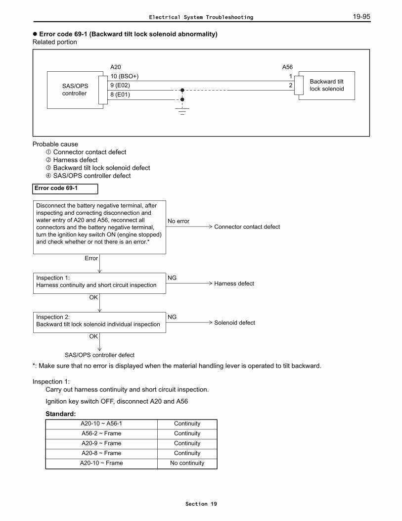
19-95
Error code 69-1 (Backward tilt lock solenoid abnormality)Related portion
Probable cause Connector contact defect Harness defect Backward tilt lock solenoid defect SAS/OPS controller defect
*: Make sure that no error is displayed when the material handling lever is operated to tilt backward.
Inspection 1: Carry out harness continuity and short circuit inspection.
Ignition key switch OFF, disconnect A20 and A56
Standard:
Error code 69-1
A20-10 ~ A56-1 Continuity
A56-2 ~ Frame Continuity
A20-9 ~ Frame Continuity
A20-8 ~ Frame Continuity
A20-10 ~ Frame No continuity
8 (E01)
Backward tilt lock solenoid
A2010 (BSO+)9 (E02)
A5612SAS/OPS
controller
NGInspection 1:Harness continuity and short circuit inspection
OK
Harness defect
NGInspection 2:Backward tilt lock solenoid individual inspection
OK
Solenoid defect
SAS/OPS controller defect
Error
No error
Disconnect the battery negative terminal, after inspecting and correcting disconnection and water entry of A20 and A56, reconnect all connectors and the battery negative terminal, turn the ignition key switch ON (engine stopped) and check whether or not there is an error.*
Connector contact defect
Electrical System Troubleshooting
Section 19
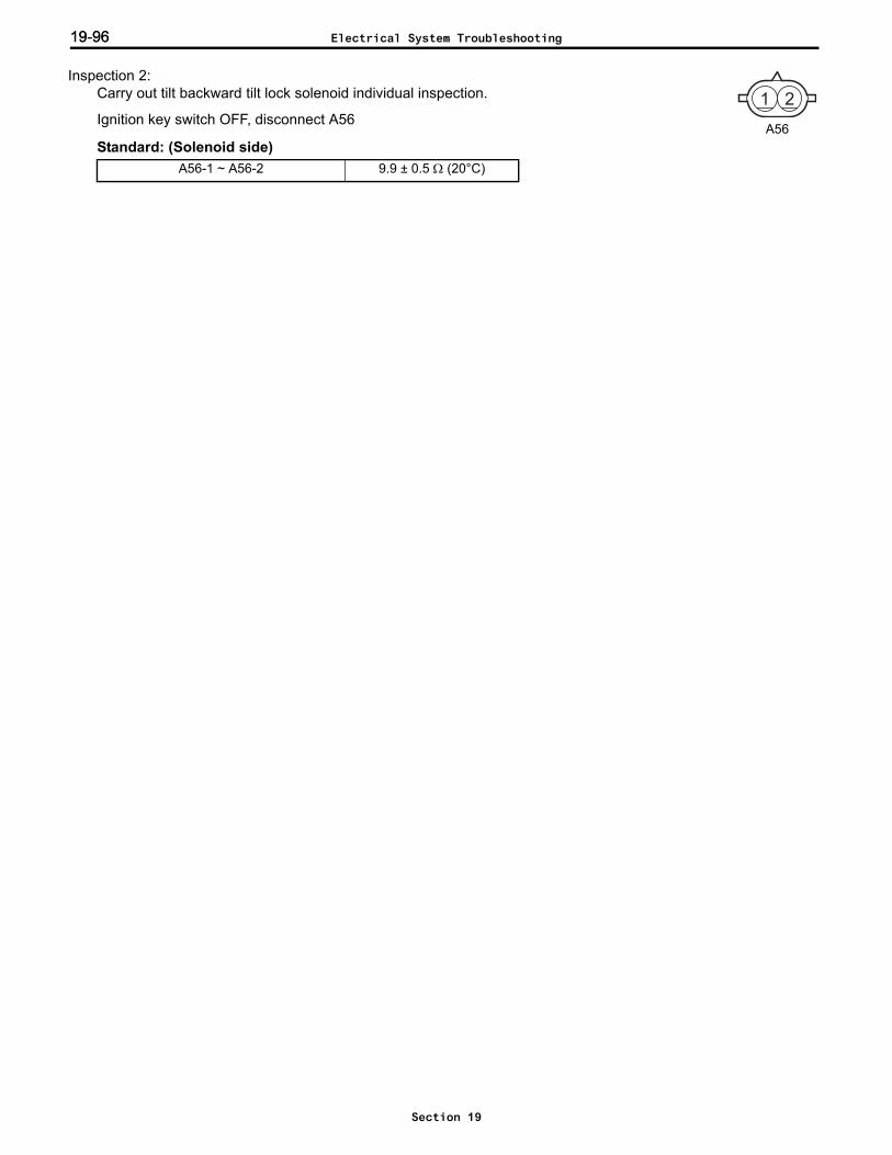
19-9619-96
Inspection 2: Carry out tilt backward tilt lock solenoid individual inspection.
Ignition key switch OFF, disconnect A56
Standard: (Solenoid side)A56-1 ~ A56-2 9.9 ± 0.5 Ω (20°C)
21
A56
Electrical System Troubleshooting
Section 19

19-97
Error codes 71-1 and 71-2 (Tire angle sensor abnormality)Related portion
Probable cause Connector contact defect Tire angle sensor harness defect Tire angle sensor defect Tire angle sensor joint, rear axle link system defect SAS/OPS controller defect
Inspection 1: Carry out tire angle sensor individual inspection.
Ignition key switch OFF, disconnect Z3, use SST 09232-13130-71 to short circuit Z3-2 and Z3-3, ignition keyswitch ON, engine stopped71-1 displayed → to inspection 271-2 displayed → Tire angle sensor defect
Error code 71-1
TA
B
RE
C
RE
C
TA
B
5 (E2)SAS/OPScontroller
Tire anglesensor
A2130 (5T)34 (T)
3Z3
2111
AO128
1
ZO143
5 (E2)
NGInspection 2:Harness continuity and short circuit inspection
OK
71-2 is displayedInspection 1:Tire angle sensor individual inspection
71-1 is displayed
Harness defect
Harness defect
OKInspection 3:Harness continuity and short circuit inspection
NG
SAS/OPS controller defect
Error
No error
Disconnect the battery negative terminal, after inspecting and correcting disconnection and water entry of Z3, AO1, ZO1 and A21, reconnect all connectors and the battery negative terminal, turn the ignition key switch ON (engine stopped) and check whether or not there is an error.
Connector contact defect
Tire angle sensor defect
Electrical System Troubleshooting
Section 19
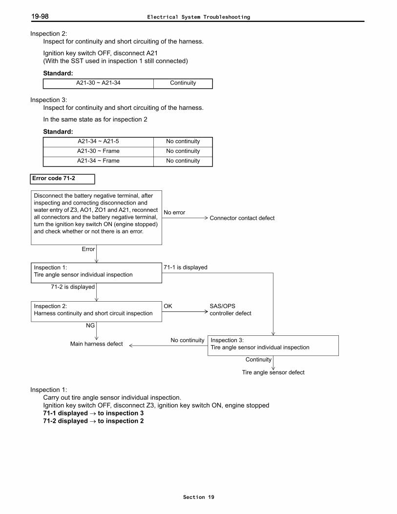
19-9819-98
Inspection 2: Inspect for continuity and short circuiting of the harness.
Ignition key switch OFF, disconnect A21(With the SST used in inspection 1 still connected)
Standard:
Inspection 3: Inspect for continuity and short circuiting of the harness.
In the same state as for inspection 2
Standard:
Inspection 1: Carry out tire angle sensor individual inspection.Ignition key switch OFF, disconnect Z3, ignition key switch ON, engine stopped71-1 displayed → to inspection 371-2 displayed → to inspection 2
A21-30 ~ A21-34 Continuity
A21-34 ~ A21-5 No continuity
A21-30 ~ Frame No continuity
A21-34 ~ Frame No continuity
Error code 71-2
OKInspection 2:Harness continuity and short circuit inspection
NG
71-1 is displayedInspection 1:Tire angle sensor individual inspection
71-2 is displayed
Main harness defect
SAS/OPScontroller defect
Tire angle sensor defect
Error
No error
Disconnect the battery negative terminal, after inspecting and correcting disconnection and water entry of Z3, AO1, ZO1 and A21, reconnect all connectors and the battery negative terminal, turn the ignition key switch ON (engine stopped) and check whether or not there is an error.
Connector contact defect
Inspection 3:Tire angle sensor individual inspection
Continuity
No continuity
Electrical System Troubleshooting
Section 19
19-99
Inspection 2: Inspect for continuity and short circuiting of the harness.
Ignition key switch OFF, disconnect A21
Standard:
Inspection 3: Carry out tire angle sensor individual inspection.
Ignition key switch OFF, disconnect Z3 and A21, use SST 09232-13130-71 to short circuit Z3-1 to Z3-2 (mainharness side)
Standard:
A21-30 ~ A21-34 No continuity
A21-34~ A21-5 Continuity
Electrical System Troubleshooting
Section 19
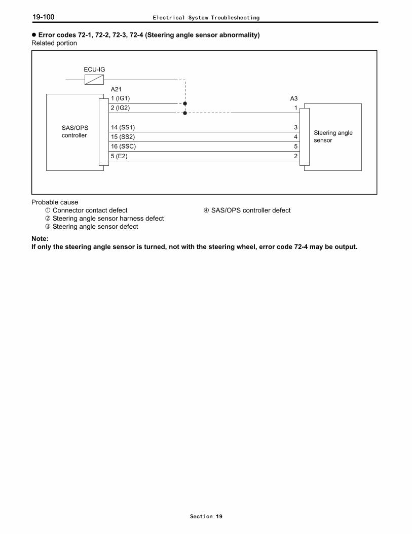
19-10019-100
Error codes 72-1, 72-2, 72-3, 72-4 (Steering angle sensor abnormality)Related portion
Probable cause Connector contact defect SAS/OPS controller defect Steering angle sensor harness defect Steering angle sensor defect
Note:If only the steering angle sensor is turned, not with the steering wheel, error code 72-4 may be output.
SAS/OPScontroller
14 (SS1)15 (SS2)16 (SSC)5 (E2)
Steering anglesensor
A31
3452
1 (IG1)A21
2 (IG2)
ECU-IG
Electrical System Troubleshooting
Section 19

19-101
Error code 72-1
Error
No error
Disconnect the battery negative terminal, after inspecting and correcting disconnection and water entry of A3 and A21, reconnect all connectors and the battery negative terminal, turn the ignition key switch ON, operate (rotate) the steering and check whether or not there is an error.
Connector contact defect
Check the STS value with an analyzer while operating the steering.ANL.: I/O STEERING 1/1
1**
0**(* is 0 or 1)
Disconnect the battery negative terminal and A3, short circuit A3-2 to A3-3 (main harness side) using SST 09232-13130-71, reconnect the battery negative terminal, and turn the ignition key switch ON.
1**
0**
Check the STS value with an analyzer while operating the steering.ANL.: I/O STEERING 1/1
Steering angle sensor defect
NGInspection 1:Harness continuity and short circuit inspection
OK
Main harness defect
SAS/OPS controller defect
Disconnect the battery negative terminal and A3, reconnect the battery negative terminal, and turn the ignition key switch ON.
0**
1**
Check the STS value with an analyzer while operating the steering.ANL.: I/O STEERING 1/1
Steering angle sensor defect
NGInspection 2:Harness continuity and short circuit inspection
OK
Main harness defect
SAS/OPS controller defect
Electrical System Troubleshooting
Section 19
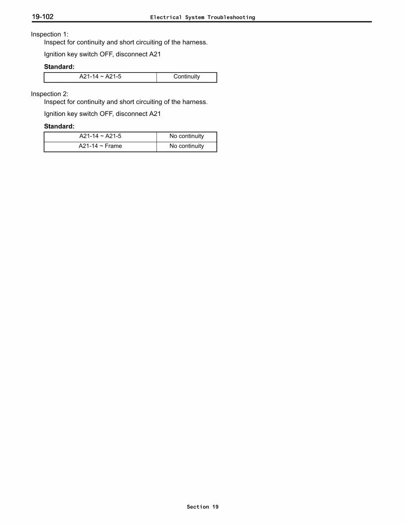
19-10219-102
Inspection 1: Inspect for continuity and short circuiting of the harness.
Ignition key switch OFF, disconnect A21
Standard:
Inspection 2: Inspect for continuity and short circuiting of the harness.
Ignition key switch OFF, disconnect A21
Standard:
A21-14 ~ A21-5 Continuity
A21-14 ~ A21-5 No continuity
A21-14 ~ Frame No continuity
Electrical System Troubleshooting
Section 19
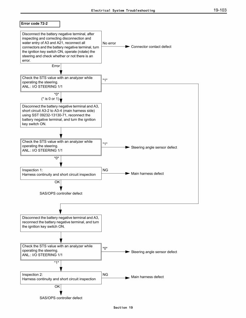
19-103
Error code 72-2
Error
No error
Disconnect the battery negative terminal, after inspecting and correcting disconnection and water entry of A3 and A21, reconnect all connectors and the battery negative terminal, turn the ignition key switch ON, operate (rotate) the steering and check whether or not there is an error.
Connector contact defect
Check the STS value with an analyzer while operating the steering.ANL.: I/O STEERING 1/1
*1*
*0*(* is 0 or 1)
Disconnect the battery negative terminal and A3, short circuit A3-2 to A3-4 (main harness side) using SST 09232-13130-71, reconnect the battery negative terminal, and turn the ignition key switch ON.
*1*
*0*
Check the STS value with an analyzer while operating the steering.ANL.: I/O STEERING 1/1
Steering angle sensor defect
NGInspection 1:Harness continuity and short circuit inspection
OK
Main harness defect
SAS/OPS controller defect
Disconnect the battery negative terminal and A3, reconnect the battery negative terminal, and turn the ignition key switch ON.
*0*
*1*
Check the STS value with an analyzer while operating the steering.ANL.: I/O STEERING 1/1
NGInspection 2:Harness continuity and short circuit inspection
OK
Main harness defect
SAS/OPS controller defect
Steering angle sensor defect
Electrical System Troubleshooting
Section 19

19-10419-104
Inspection 1: Inspect for continuity and short circuiting of the harness.
Ignition key switch OFF, disconnect A21
Standard:
Inspection 2: Inspect for continuity and short circuiting of the harness.
Ignition key switch OFF, disconnect A21
Standard:
A21-15 ~ A21-5 Continuity
A21-15 ~ A21-5 No continuity
A21-15 ~ Frame No continuity
Electrical System Troubleshooting
Section 19
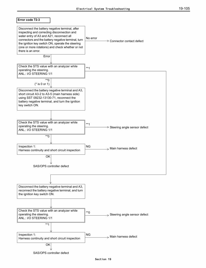
19-105
Error code 72-3
Error
Connector contact defect
Check the STS value with an analyzer while operating the steering.ANL.: I/O STEERING 1/1
**1
**0(* is 0 or 1)
Disconnect the battery negative terminal and A3, short circuit A3-2 to A3-5 (main harness side) using SST 09232-13130-71, reconnect the battery negative terminal, and turn the ignition key switch ON.
**1
**0
Check the STS value with an analyzer while operating the steering.ANL.: I/O STEERING 1/1
Steering angle sensor defect
NGInspection 1:Harness continuity and short circuit inspection
OK
Main harness defect
SAS/OPS controller defect
Disconnect the battery negative terminal and A3, reconnect the battery negative terminal, and turn the ignition key switch ON.
**0
**1
Check the STS value with an analyzer while operating the steering.ANL.: I/O STEERING 1/1
Steering angle sensor defect
NGInspection 1:Harness continuity and short circuit inspection
OK
Main harness defect
SAS/OPS controller defect
Disconnect the battery negative terminal, after inspecting and correcting disconnection and water entry of A3 and A21, reconnect all connectors and the battery negative terminal, turn the ignition key switch ON, operate the steering (one or more rotations) and check whether or not there is an error.
No error
Electrical System Troubleshooting
Section 19
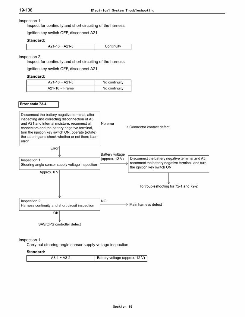
19-10619-106
Inspection 1: Inspect for continuity and short circuiting of the harness.
Ignition key switch OFF, disconnect A21
Standard:
Inspection 2: Inspect for continuity and short circuiting of the harness.
Ignition key switch OFF, disconnect A21
Standard:
Inspection 1: Carry out steering angle sensor supply voltage inspection.
Standard:
A21-16 ~ A21-5 Continuity
A21-16 ~ A21-5 No continuity
A21-16 ~ Frame No continuity
Error code 72-4
A3-1 ~ A3-2 Battery voltage (approx. 12 V)
Error
No error
Disconnect the battery negative terminal, after inspecting and correcting disconnection of A3 and A21 and internal moisture, reconnect all connectors and the battery negative terminal, turn the ignition key switch ON, operate (rotate) the steering and check whether or not there is an error.
Connector contact defect
Disconnect the battery negative terminal and A3, reconnect the battery negative terminal, and turn the ignition key switch ON.
NGInspection 2:Harness continuity and short circuit inspection
OK
Main harness defect
SAS/OPS controller defect
Battery voltage (approx. 12 V)Inspection 1:
Steering angle sensor supply voltage inspection
Approx. 0 V
To troubleshooting for 72-1 and 72-2
Electrical System Troubleshooting
Section 19
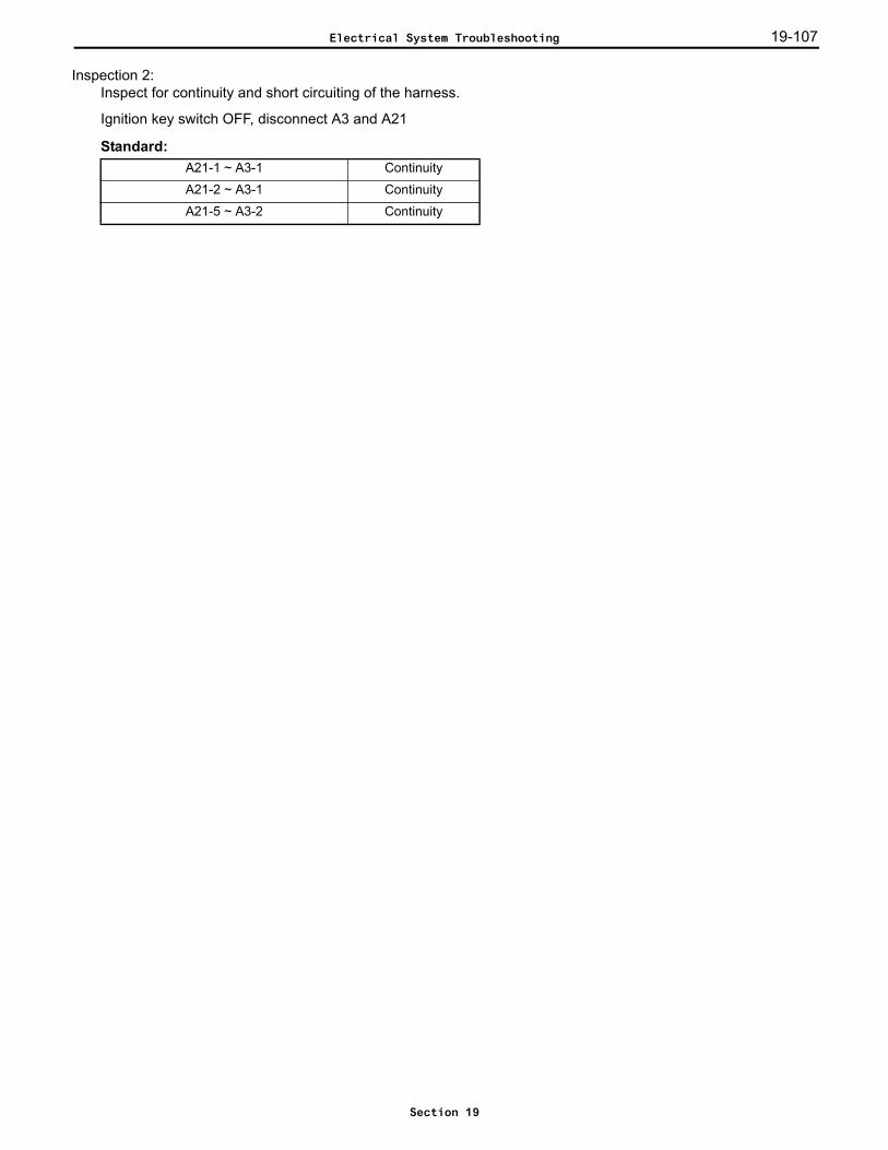
19-107
Inspection 2: Inspect for continuity and short circuiting of the harness.
Ignition key switch OFF, disconnect A3 and A21
Standard:A21-1 ~ A3-1 Continuity
A21-2 ~ A3-1 Continuity
A21-5 ~ A3-2 Continuity
Electrical System Troubleshooting
Section 19
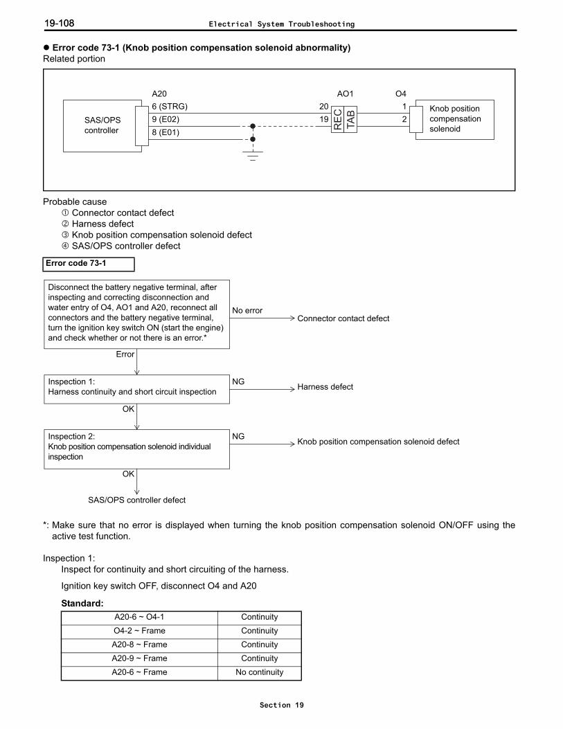
19-10819-108
Error code 73-1 (Knob position compensation solenoid abnormality)Related portion
Probable cause Connector contact defect Harness defect Knob position compensation solenoid defect SAS/OPS controller defect
*: Make sure that no error is displayed when turning the knob position compensation solenoid ON/OFF using theactive test function.
Inspection 1: Inspect for continuity and short circuiting of the harness.
Ignition key switch OFF, disconnect O4 and A20
Standard:
Error code 73-1
A20-6 ~ O4-1 Continuity
O4-2 ~ Frame Continuity
A20-8 ~ Frame Continuity
A20-9 ~ Frame Continuity
A20-6 ~ Frame No continuity
TA
B
RE
C
SAS/OPScontroller
Knob position compensationsolenoid
O4A206 (STRG)9 (E02)8 (E01)
12
AO12019
NGInspection 1:Harness continuity and short circuit inspection
OK
Harness defect
NGInspection 2:Knob position compensation solenoid individual inspection
OK
Knob position compensation solenoid defect
SAS/OPS controller defect
Error
No error
Disconnect the battery negative terminal, after inspecting and correcting disconnection and water entry of O4, AO1 and A20, reconnect all connectors and the battery negative terminal, turn the ignition key switch ON (start the engine) and check whether or not there is an error.*
Connector contact defect
Electrical System Troubleshooting
Section 19
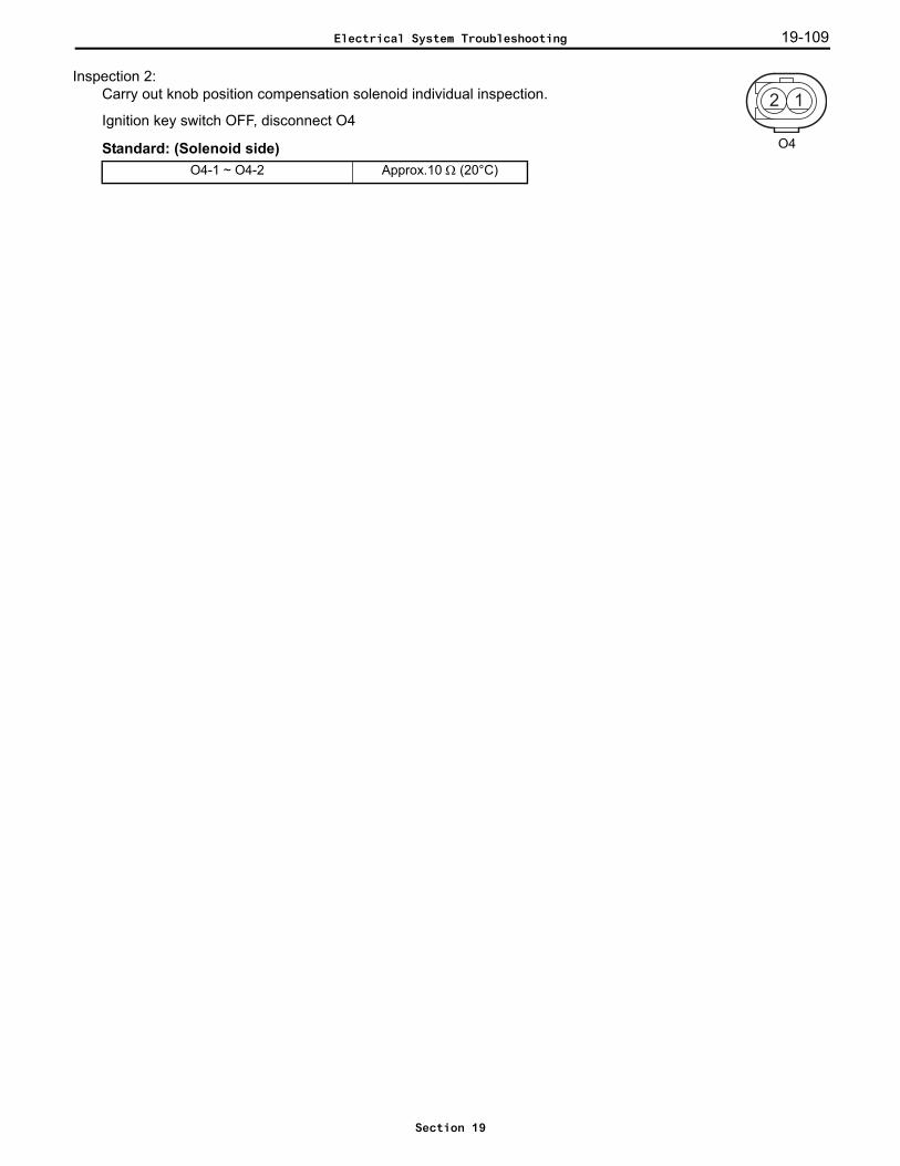
19-109
Inspection 2: Carry out knob position compensation solenoid individual inspection.
Ignition key switch OFF, disconnect O4
Standard: (Solenoid side)O4-1 ~ O4-2 Approx.10 Ω (20°C)
2 1
O4
Electrical System Troubleshooting
Section 19
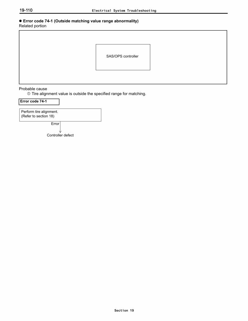
19-11019-110
Error code 74-1 (Outside matching value range abnormality)Related portion
Probable cause Tire alignment value is outside the specified range for matching.
Error code 74-1
SAS/OPS controller
Perform tire alignment.(Refer to section 18)
Error
Controller defect
Electrical System Troubleshooting
Section 19
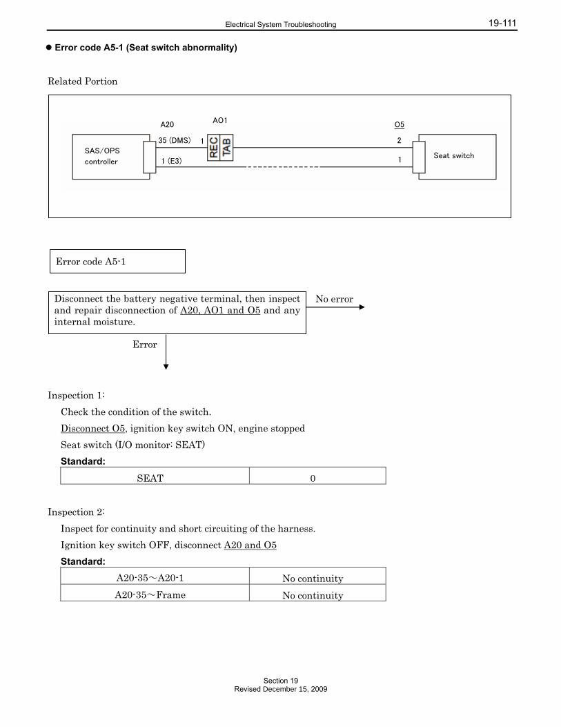
19-111
Error code A5-1 (Seat switch abnormality)
ry negative terminal, then inspect and repair disconnection and water entry of A20, AO1, XO4 and X1.*
Connector contact defect
Related Portion
Inspection 1:
Check the condition of the switch.
Disconnect O5, ignition key switch ON, engine stopped
Seat switch (I/O monitor: SEAT)
Standard:
SEAT 0
Inspection 2:
Inspect for continuity and short circuiting of the harness.
Ignition key switch OFF, disconnect A20 and O5
Standard:
A20-35~A20-1 No continuity
A20-35~Frame No continuity
Error code A5-1
Disconnect the battery negative terminal, then inspect and repair disconnection of A20, AO1 and O5 and any internal moisture.
No error
Error
SAS/OPS
controller
A20
35 (DMS)
1 (E3)
AO1
1
O5
2
1 Seat switch
Electrical System Troubleshooting
Section 19Revised December 15, 2009
19-11219-112 Memo
Section 19Revised December 15, 2009

19-113
Error code A7-1 (Brake switch abnormality)Related portion
Probable cause Connector contact defect Brake switch defect Harness defect SAS/OPS controller defect
*: After correcting, connect the connector and turn the ignition key switch OFF → ON (at least 2 seconds) → OFF.Make sure that no error is displayed when the ignition key is turned ON after leaving the vehicle with the seatempty for 15 minutes.
Inspection 1: Check the condition of the switch.
Disconnect A6, ignition key switch ON, engine stoppedBrake switch (I/O monitor: BRKSW)
Standard:
Error code A7-1
BRKSW 0
SAS/OPScontroller 17 (BSW)
A201
A6
2
STOP
Brake switch
OKOK
No error
Error
Brake switch installation defect
Inspection 3:Individual continuity inspection of the brake switch (removed from the vehicle)
OK
NG
Inspection 2:Harness continuity and short circuit inspection
SAS/OPS controller defect
NGInspection 1:Check the condition of the switchANL.: I/O TRAVELING 1/3
NG Harness defect
Brake switch defect
Disconnect the battery negative terminal, then inspect and repair disconnection and water entry of A20 and A6.*
Connector contact defect
Electrical System Troubleshooting
Section 19
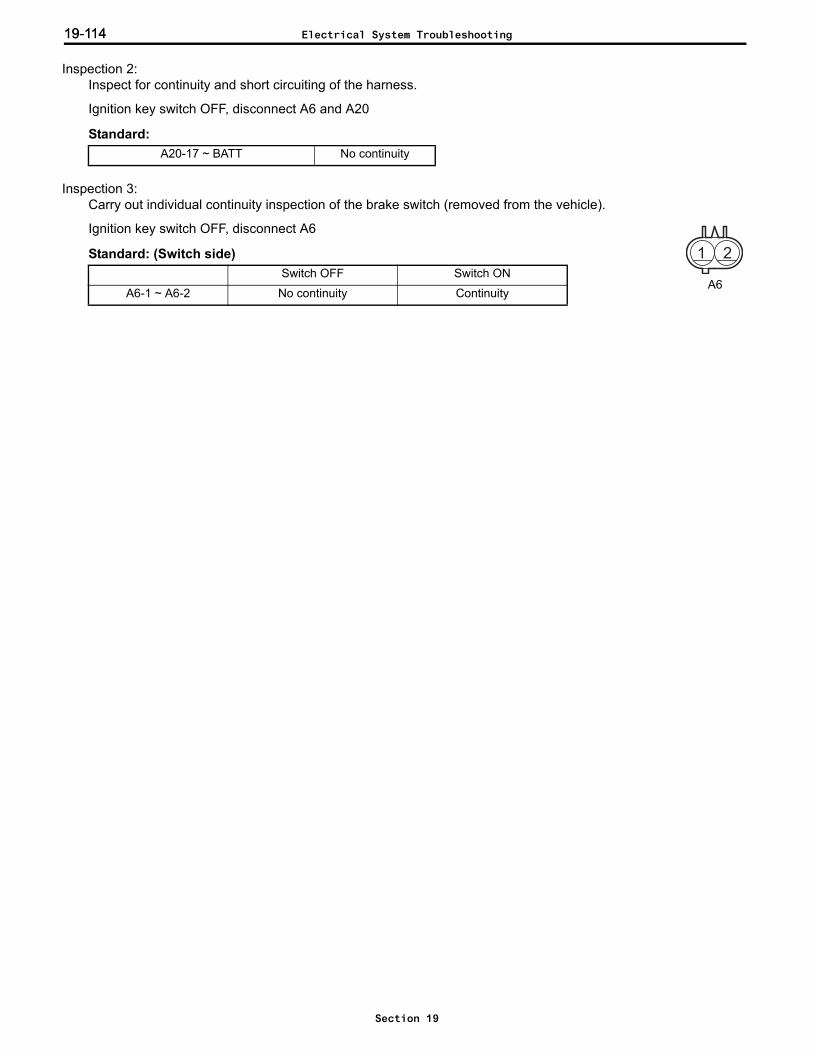
19-11419-114
Inspection 2: Inspect for continuity and short circuiting of the harness.
Ignition key switch OFF, disconnect A6 and A20
Standard:
Inspection 3: Carry out individual continuity inspection of the brake switch (removed from the vehicle).
Ignition key switch OFF, disconnect A6
Standard: (Switch side)
A20-17 ~ BATT No continuity
Switch OFF Switch ON
A6-1 ~ A6-2 No continuity Continuity
1 2
A6
Electrical System Troubleshooting
Section 19

19-115
Error codes AD-1, AD-2, AD-7, AD-8 (4Y-E spec.) (CAN communication abnormality)Related portion
Probable cause Connector contact defect Engine controller defect Engine controller harness defect Multifunction display defect Multifunction display harness defect SAS/OPS controller defect Fuse defect
Caution:When the controller or optional display is replaced into another vehicle with different specifications, AD-1and AD-7 may occur. In such cases, perform "Engine and display ECU information clear".
Error codes AD-1, AD-2, AD-7, AD-8
TA
B
RE
C
SAS/OPS controller
8 (BATT)A21
1 (IG1)
28 (CAN+)29 (CAN-)
A36
Multi-function display
Engine controller
3 (BATT)
9 (IGSW)
2 (IG)
5 (CANH)
Q2
6 (CANL)3 (E1)
2 (IG2)
12 (CANH)13 (CANL)
A20
ECU-B
ECU-IG
EFI
IGN
AQ12
143
NGDisconnect the negative terminal of the battery and inspect the fuses.
OK
Fuse defect
No error
Disconnect the battery negative terminal (for more than 10 seconds), after inspecting and correcting disconnection and water entry of A20, A21, A36, AQ1 and Q2, reconnect all connectors and the battery negative terminal, turn the ignition key switch ON and check whether or not there is an error.*
Error
Connector contact defect
NGInspection 1:Harness continuity and short circuit inspection
OK
Harness defect
Engine controller defect (AD-1)Multifunction display defect (AD-7)SAS/OPS controller defect (AD-8)
SAS/OPS controller orengine controller defect (AD-2)
Electrical System Troubleshooting
Section 19

19-11619-116
*: It is not necessary to inspect A36 when AD-1 and AD-2 have not occurred, and Q2 when AD-7 and AD-8 have notoccurred.
Inspection 1: Inspect for continuity and short circuiting of the harness.
Ignition key switch OFF, disconnect Q2 (unnecessary if AD-7 and AD-8 have not occurred), A20, A21 and A36(unnecessary if AD-1 and AD-2 have not occured)
Standard:A21-8 ~ ECU-B Continuity
A21-1 ~ ECU-IG Continuity
A21-2 ~ ECU-IG Continuity
Q2-2 ~ ECU-IG Continuity
A20-12 ~ Q2-5 Continuity
A20-13 ~ Q2-6 Continuity
A20-12 ~ A36-28 Continuity
A20-13 ~ A36-29 Continuity
A20-12 ~ Frame No continuity
A20-13 ~ Frame No continuity
A36-3 ~ EFI Continuity
A36-9 ~ IGN Continuity
Electrical System Troubleshooting
Section 19
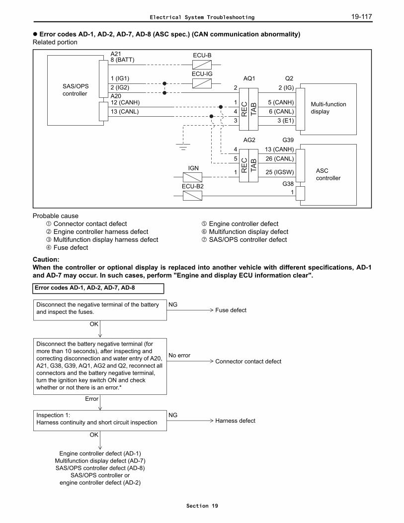
19-117
Error codes AD-1, AD-2, AD-7, AD-8 (ASC spec.) (CAN communication abnormality)Related portion
Probable cause Connector contact defect Engine controller defect Engine controller harness defect Multifunction display defect Multifunction display harness defect SAS/OPS controller defect Fuse defect
Caution:When the controller or optional display is replaced into another vehicle with different specifications, AD-1and AD-7 may occur. In such cases, perform "Engine and display ECU information clear".
Error codes AD-1, AD-2, AD-7, AD-8
TA
B
RE
C
TA
B
RE
C
SAS/OPS controller
8 (BATT)A21
1 (IG1)
13 (CANH)26 (CANL)
G39
Multi-function display
ASC controller
G38
25 (IGSW)
2 (IG)
5 (CANH)
Q2
6 (CANL)3 (E1)
2 (IG2)
12 (CANH)13 (CANL)
A20
ECU-B
ECU-IG
ECU-B2
IGN
AQ12
143
AG245
1
1
NGDisconnect the negative terminal of the battery and inspect the fuses.
OK
Fuse defect
No error
Disconnect the battery negative terminal (for more than 10 seconds), after inspecting and correcting disconnection and water entry of A20, A21, G38, G39, AQ1, AG2 and Q2, reconnect all connectors and the battery negative terminal, turn the ignition key switch ON and check whether or not there is an error.*
Error
Connector contact defect
NGInspection 1:Harness continuity and short circuit inspection
OK
Harness defect
Engine controller defect (AD-1)Multifunction display defect (AD-7)SAS/OPS controller defect (AD-8)
SAS/OPS controller orengine controller defect (AD-2)
Electrical System Troubleshooting
Section 19
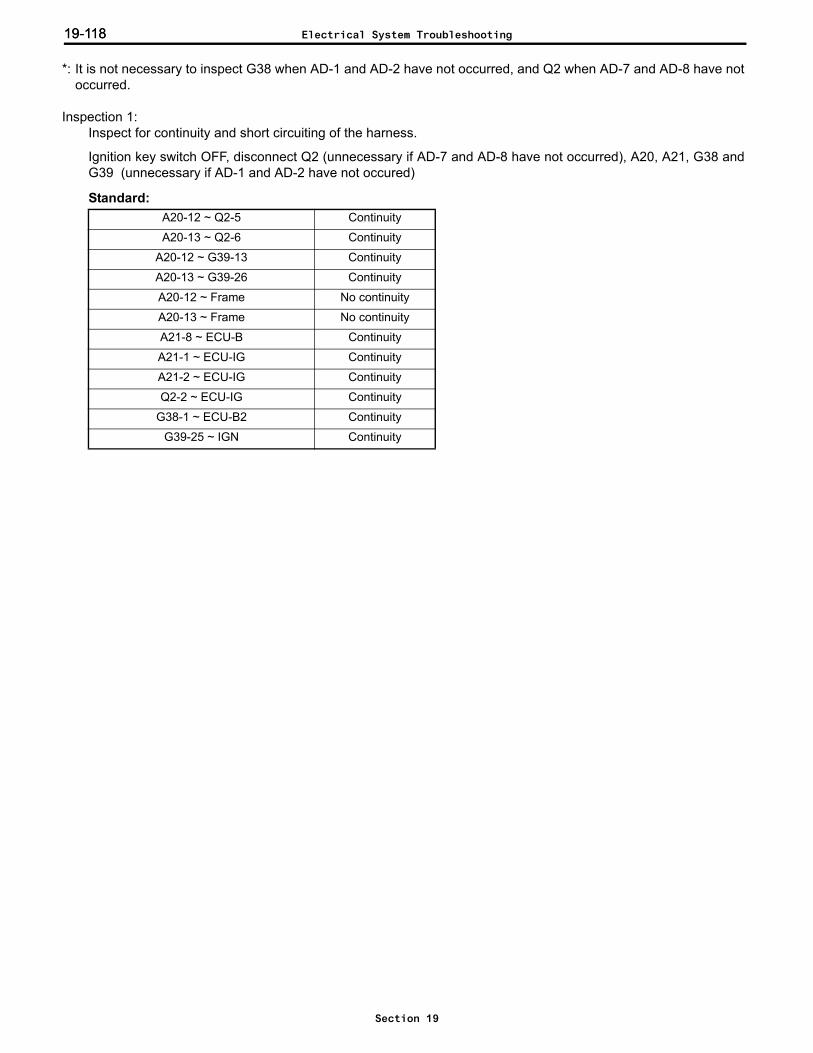
19-11819-118
*: It is not necessary to inspect G38 when AD-1 and AD-2 have not occurred, and Q2 when AD-7 and AD-8 have notoccurred.
Inspection 1: Inspect for continuity and short circuiting of the harness.
Ignition key switch OFF, disconnect Q2 (unnecessary if AD-7 and AD-8 have not occurred), A20, A21, G38 andG39 (unnecessary if AD-1 and AD-2 have not occured)
Standard:A20-12 ~ Q2-5 Continuity
A20-13 ~ Q2-6 Continuity
A20-12 ~ G39-13 Continuity
A20-13 ~ G39-26 Continuity
A20-12 ~ Frame No continuity
A20-13 ~ Frame No continuity
A21-8 ~ ECU-B Continuity
A21-1 ~ ECU-IG Continuity
A21-2 ~ ECU-IG Continuity
Q2-2 ~ ECU-IG Continuity
G38-1 ~ ECU-B2 Continuity
G39-25 ~ IGN Continuity
Electrical System Troubleshooting
Section 19
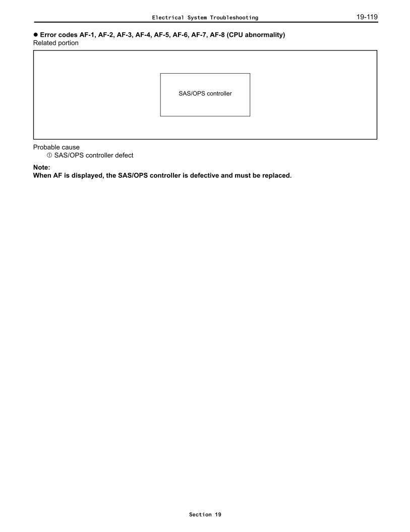
19-119
Error codes AF-1, AF-2, AF-3, AF-4, AF-5, AF-6, AF-7, AF-8 (CPU abnormality)Related portion
Probable cause SAS/OPS controller defect
Note:When AF is displayed, the SAS/OPS controller is defective and must be replaced.
SAS/OPS controller
Electrical System Troubleshooting
Section 19

19-12019-120
Error codes C4-1, C4-2, C4-3, C4-4, C4-5, C4-6 (4Y-E spec.) (Accelerator sensor abnormality)Related portion
Probable cause Connector contact defect Accelerator sensor defect Harness defect Engine controller defect
*: Make sure that no error code is displayed when the accelerator pedal is operated.
Error codes C4-1, C4-2, C4-3, C4-4, C4-5
TA
B
RE
CEngine controller
Accelerator sensor
A35 a125 (VCPA)26 (VPA)27 (EPA)33 (VCP2)34 (VPA2)35 (EPA2)
5 (VCP1)4 (VPA1)6 (EP1)1 (VCP2)3 (VPA2)2 (EPA2)
Aa148237
1
NGInspection 1:Accelerator sensor individual inspection Accelerator sensor defect
OK
NGInspection 2:Harness continuity and short circuit inspection Harness defect
OK
Engine controller defect
No error
Disconnect the battery negative terminal, after inspecting and correcting disconnection and water entry of A35, Aa1 and a1, reconnect all connectors and the battery negative terminal, turn the ignition key switch ON (start the engine), and check whether or not there is an error.*
Error
Connector contact defect
Electrical System Troubleshooting
Section 19

19-121
*: Make sure that no error code is displayed when the accelerator pedal is operated.
Inspection 1: Carry out accelerator sensor individual inspection.
Ignition key switch OFF, disconnect a1, conenct A35(1) Accelerator sensor resistance measurement
Standard: (Sensor side)
(2) Accelerator sensor output circuit resistance measurement
Standard: (Sensor side)
Error code C4-5
a1-5 ~ a1-6 Approx. 1.8 ~ 3.5 kΩ (released)a1-1 ~ a1-2
a1-4 ~ a1-6 Make sure that the resistance value increases proportionally to the rotation of the potentiometer when the potentiometer section is rotated.a1-3 ~ a1-2
NGInspection 1:Accelerator sensor individual inspection Accelerator sensor defect
OK
NGInspection 2:Harness continuity and short circuit inspection Harness defect
OK
NG
OK
Accelerator sensor defectInspection 3:Accelerator sensor voltage inspectionANL.: I/O ENGINE CTRL 4/10
Engine controller defect
No error
Disconnect the battery negative terminal, after inspecting and correcting disconnection and water entry of A35, Aa1 and a1, reconnect all connectors and the battery negative terminal, turn the ignition key switch ON (start the engine) and check whether or not there is an error.*
Error
Connector contact defect
123456
a1
Electrical System Troubleshooting
Section 19

19-12219-122
Inspection 2: Inspect for continuity and short circuiting of the harness.
Ignition key switch OFF, disconnect A35 and a1
Standard:
Inspection 3: Inspect the accelerator sensor voltage.
Ignition key switch OFF, disconnect a1, connect A35, ignition key switch ONAccelerator sensor (I/O monitor: VPA1, VPA2)
Standard:
A35-26 ~ a1-4 Continuity
A35-25 ~ a1-5 Continuity
A35-26 ~ Frame No continuity
A35-27 ~ a1-6 Continuity
A35-25 ~ A35-26 No continuity
A35-26 ~ A35-33 No continuity
A35-34 ~ a1-3 Continuity
A35-33 ~ a1-1 Continuity
A35-34 ~ Frame No continuity
A35-34 ~ A35-25 No continuity
A35-34 ~ A35-33 No continuity
A35-26 ~ A35-34 No continuity
VPA1 0.20 V or less
VPA2 0.20 V or less
Electrical System Troubleshooting
Section 19
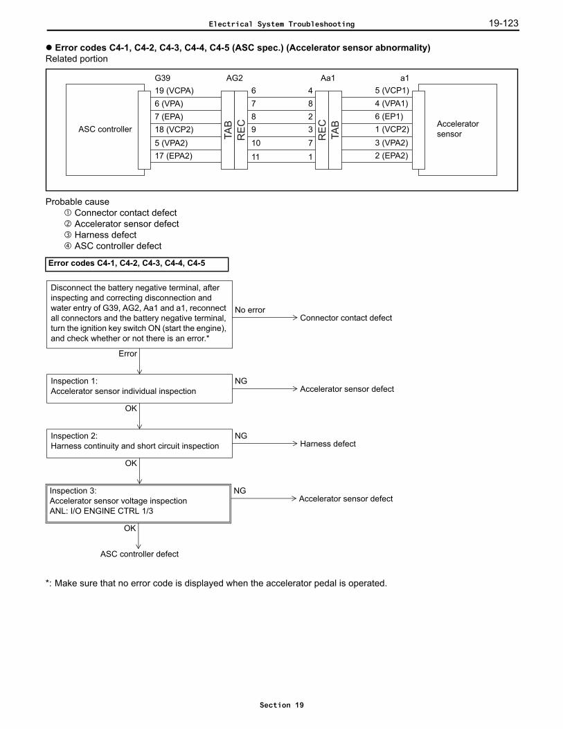
19-123
Error codes C4-1, C4-2, C4-3, C4-4, C4-5 (ASC spec.) (Accelerator sensor abnormality)Related portion
Probable cause Connector contact defect Accelerator sensor defect Harness defect ASC controller defect
*: Make sure that no error code is displayed when the accelerator pedal is operated.
Error codes C4-1, C4-2, C4-3, C4-4, C4-5
TA
B
RE
C
RE
C
TA
BASC controller Accelerator sensor
G39 a119 (VCPA)6 (VPA)7 (EPA)18 (VCP2)5 (VPA2)17 (EPA2)
5 (VCP1)4 (VPA1)6 (EP1)1 (VCP2)3 (VPA2)2 (EPA2)
Aa148237
1
AG2678910
11
NGInspection 1:Accelerator sensor individual inspection Accelerator sensor defect
OK
NGInspection 2:Harness continuity and short circuit inspection Harness defect
OK
ASC controller defect
No error
Disconnect the battery negative terminal, after inspecting and correcting disconnection and water entry of G39, AG2, Aa1 and a1, reconnect all connectors and the battery negative terminal, turn the ignition key switch ON (start the engine), and check whether or not there is an error.*
Error
Connector contact defect
NGInspection 3:Accelerator sensor voltage inspectionANL: I/O ENGINE CTRL 1/3
Accelerator sensor defect
OK
Electrical System Troubleshooting
Section 19

19-12419-124
Inspection 1: Carry out accelerator sensor individual inspection.
Ignition key switch OFF, disconnect a1, conenct G39(1) Accelerator sensor resistance measurement
Standard: (Sensor side)
(2) Accelerator sensor output circuit resistance measurement
Standard: (Sensor side)
a1-5 ~ a1-6 Approx. 1.8 ~ 3.5 kΩ (released)a1-1 ~ a1-2
a1-4 ~ a1-6 Make sure that the resistance value increases proportionally to the rotation of the potentiometer when the potentiometer section is rotated.a1-3 ~ a1-2
123456
a1
Electrical System Troubleshooting
Section 19

19-125
Inspection 2: Inspect for continuity and short circuiting of the harness.
Ignition key switch OFF, disconnect G39 and a1
Standard:
Inspection 3: Inspect the accelerator sensor voltage.
Ignition key switch OFF, disconnect a1, connect G39, ignition key switch ONAccelerator sensor (I/O monitor: VPA1, VPA2)
Standard:
G39-6 ~ a1-4 Continuity
G39-19 ~ a1-5 Continuity
G39-6 ~ Frame No continuity
G39-7 ~ a1-6 Continuity
G39-19 ~ G39-6 No continuity
G39-6 ~ G39-18 No continuity
G39-5 ~ a1-3 Continuity
G39-18 ~ a1-1 Continuity
G39-5 ~ Frame No continuity
G39-5 ~ G39-19 No continuity
G39-5 ~ G39-18 No continuity
G39-6 ~ G39-5 No continuity
VPA1 0.20 V or less
VPA2 0.20 V or less
Electrical System Troubleshooting
Section 19

19-12619-126
Error codes C7-1 and C7-2 (Shift lever switch abnormality)Related portion
The above chart is for vehicles of the left shift lever column specification.For vehicles of the right shift lever column specification, A43-4, A43-5 and A43-9 should be used.For vehicles of the armrest specification, Y4-7, Y4-6 and Y4-1 should be used.
Probable cause Connector contact defect Harness defect Forward travel shift switch defect Shift switch installation defect Reverse travel shift switch defect SAS/OPS controller defect
Note:In the event that the engine stops while travelling, when the ignition key switch is turned from OFF to ON, anC7-1 error may be detected, however this is not a fault.Stop the vehicle, turn the ignition key switch OFF and restart the engine.
SAS/OPScontroller Shift switch18 (DRF)
19 (DRR)
SFT
A41
51
A206
Electrical System Troubleshooting
Section 19

19-127
*: Check if an error occurs after turning the ignition key switch ON, moving the shift lever and traveling from stoppedstate to more than 10 km/h (6.2 mph) within 3 seconds.
*: Make sure there is no error after turning the ignition key switch ON, and move the shift lever to forward and reversetravel.
Error code C7-1
Error code C7-2
NG
Inspection 1:Check the condition of the switchANL.: I/O TRAVELING 2/3
NGInspection 3:Harness continuity and short circuit inspection
OK
Harness defect
SAS/OPS controller defect
NGInspection 2:Individual continuity inspection of the direction lever switch that was abnormal in inspection 1 (while still installed on the vehicle).
Shift switch defect
OK
No error
Disconnect the battery negative terminal, after inspecting and correcting disconnection of A20 and A41 and internal moisture, reconnect all connectors and the battery negative terminal, turn the ignition key switch ON (start the engine) and check whether or not there is an error.*
Error
Connector contact defect
NG
Inspection 4:Check the condition of the switchANL.: I/O TRAVELING 2/3
OKInspection 3:Harness continuity and short circuit inspection
NG
Harness defect
SAS/OPS controller defect
OKShift switch defect
No error
Disconnect the battery negative terminal, after inspecting and correcting disconnection of A20 and A41 and internal moisture, reconnect all connectors and the battery negative terminal, turn the ignition key switch ON (start the engine) and check whether or not there is an error.*
Error
Connector contact defect
Electrical System Troubleshooting
Section 19
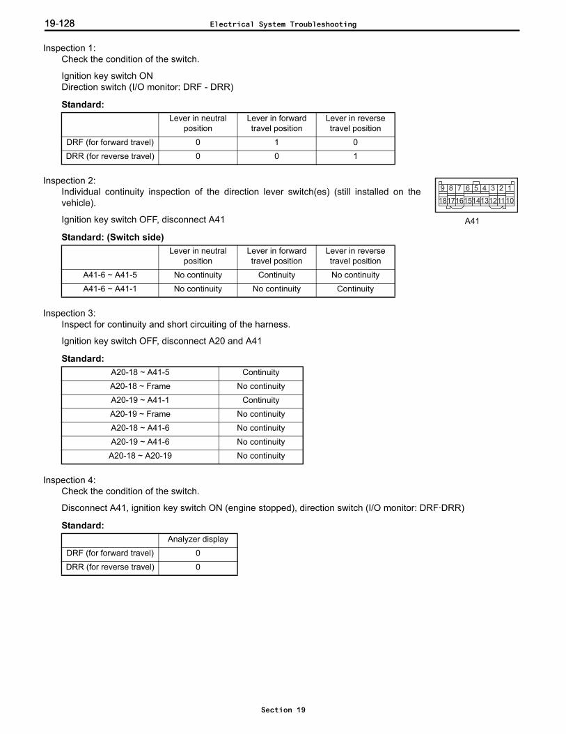
19-12819-128
Inspection 1: Check the condition of the switch.
Ignition key switch ONDirection switch (I/O monitor: DRF - DRR)
Standard:
Inspection 2: Individual continuity inspection of the direction lever switch(es) (still installed on thevehicle).
Ignition key switch OFF, disconnect A41
Standard: (Switch side)
Inspection 3: Inspect for continuity and short circuiting of the harness.
Ignition key switch OFF, disconnect A20 and A41
Standard:
Inspection 4: Check the condition of the switch.
Disconnect A41, ignition key switch ON (engine stopped), direction switch (I/O monitor: DRF·DRR)
Standard:
Lever in neutral position
Lever in forward travel position
Lever in reverse travel position
DRF (for forward travel) 0 1 0
DRR (for reverse travel) 0 0 1
Lever in neutral position
Lever in forward travel position
Lever in reverse travel position
A41-6 ~ A41-5 No continuity Continuity No continuity
A41-6 ~ A41-1 No continuity No continuity Continuity
A20-18 ~ A41-5 Continuity
A20-18 ~ Frame No continuity
A20-19 ~ A41-1 Continuity
A20-19 ~ Frame No continuity
A20-18 ~ A41-6 No continuity
A20-19 ~ A41-6 No continuity
A20-18 ~ A20-19 No continuity
Analyzer display
DRF (for forward travel) 0
DRR (for reverse travel) 0
123456789
101112131415161718
A41
Electrical System Troubleshooting
Section 19
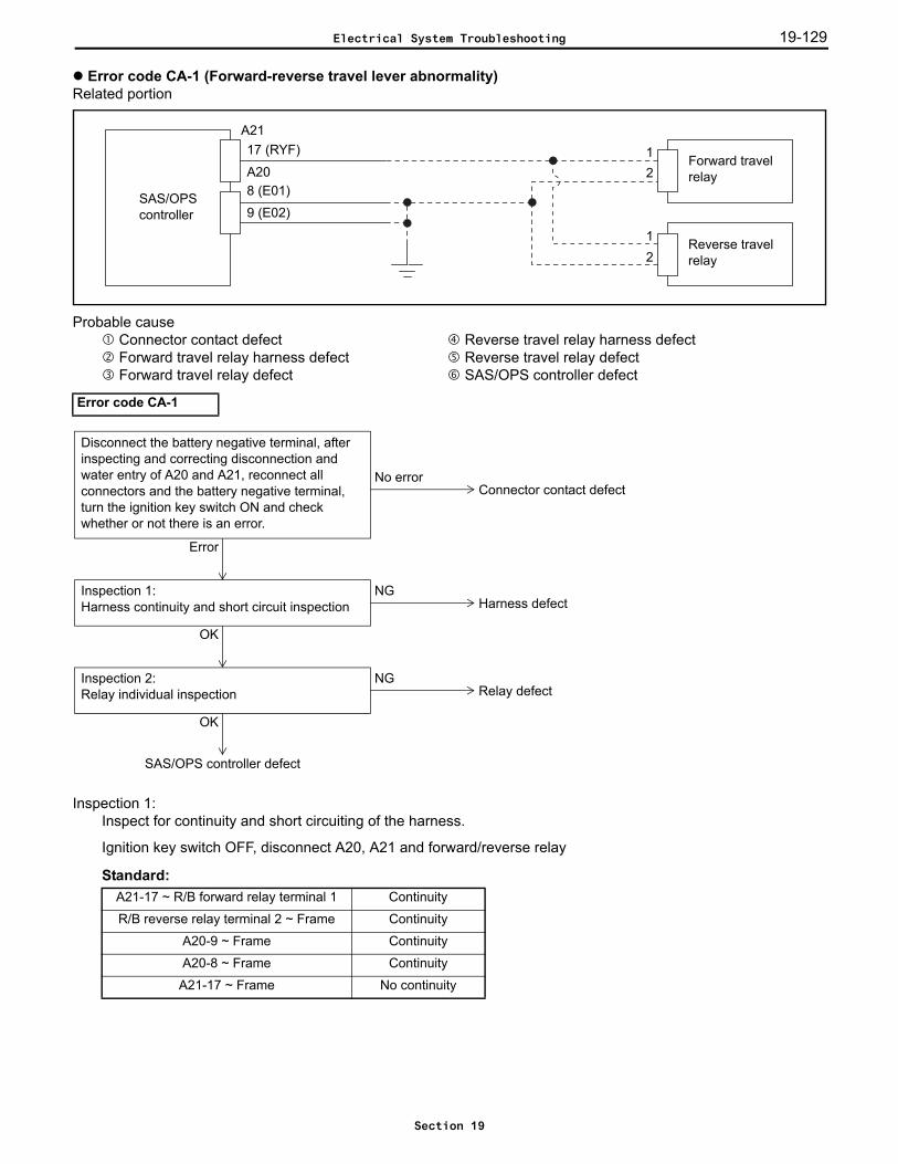
19-129
Error code CA-1 (Forward-reverse travel lever abnormality)Related portion
Probable cause Connector contact defect Reverse travel relay harness defect Forward travel relay harness defect Reverse travel relay defect Forward travel relay defect SAS/OPS controller defect
Inspection 1: Inspect for continuity and short circuiting of the harness.
Ignition key switch OFF, disconnect A20, A21 and forward/reverse relay
Standard:
Error code CA-1
A21-17 ~ R/B forward relay terminal 1 Continuity
R/B reverse relay terminal 2 ~ Frame Continuity
A20-9 ~ Frame Continuity
A20-8 ~ Frame Continuity
A21-17 ~ Frame No continuity
A21
SAS/OPScontroller
17 (RYF)
8 (E01)
12
Forward travel relay
Reverse travel relay
12
9 (E02)
A20
OK
NGInspection 2:Relay individual inspection
OK
Relay defect
SAS/OPS controller defect
No error
Disconnect the battery negative terminal, after inspecting and correcting disconnection and water entry of A20 and A21, reconnect all connectors and the battery negative terminal, turn the ignition key switch ON and check whether or not there is an error.
Error
Connector contact defect
NGInspection 1:Harness continuity and short circuit inspection Harness defect
Electrical System Troubleshooting
Section 19
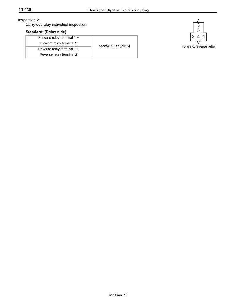
19-13019-130
Inspection 2: Carry out relay individual inspection.
Standard: (Relay side)Forward relay terminal 1 ~ Forward relay terminal 2
Approx. 90 Ω (20°C)Reverse relay terminal 1 ~ Reverse relay terminal 2
Forward/reverse relay
Electrical System Troubleshooting
Section 19

19-131
Error code EC-1 (Unload solenoid abnormality)Related portion
Probable cause Connector contact defect Harness defect Unload solenoid defect SAS/OPS controller defect
*: Check whether an error occurs after turning the ignition key switch ON and leaving the seat (for at least 2seconds).
Inspection 1: Carry out unload solenoid individual inspection.
Ignition key switch OFF, disconnect A12
Standard: (Solenoid side)
Error code EC-1
A12-1 ~ A12-2 Approx. 10 Ω (20°C)
8 (E01)
Unloadsolenoid
A205 (USOL)9 (E02)
A1212SAS/OPS
controller
NGInspection 1:Unload solenoid individual inspection
OK
Unload solenoid defect
NGInspection 2:Harness continuity and short circuit inspection
OK
Harness defect
SAS/OPS controller defect
No error
Disconnect the battery negative terminal, after inspecting and correcting disconnection and water entry of A12 and A20, reconnect all connectors and the battery negative terminal, turn the ignition key switch ON (start the engine) and check whether or not there is an error.*
Error
Connector contact defect
1 2
A12
Electrical System Troubleshooting
Section 19

19-13219-132
Inspection 2: Inspect for continuity and short circuiting of the harness.
Ignition key switch OFF, disconnect A20 and A12
Standard:A20-5 ~ A12-1 Continuity
A12-2 ~ Frame Continuity
A20-8 ~ Frame Continuity
A20-9 ~ Frame Continuity
A20-5 ~ Frame No continuity
Electrical System Troubleshooting
Section 19

19-133
Error codes F1-1, F2-1 (Controller to combination meter communication abnormality)Related portion
Probable cause Connector contact defect Hour meter harness defect Hour meter defect SAS/OPS controller defect
Inspection 1: Inspect for continuity and short circuiting of the harness.
Ignition key switch OFF, disconnect A20 and Q1
Standard:
Error codes F1-1, F2-1
Q1-3 ~ Frame No continuity
A20-14 ~ Q1-3 Continuity
RE
C
TA
B
A20
14 (SIL) Combination meter
SAS/OPS controller
Q1
3 (SIL2)
QA1
10
Disconnect the battery negative terminal, after inspecting and correcting disconnection and water entry of A20, QA1 and Q1, reconnect all connectors and the battery negative terminal, turn the ignition key switch ON and check whether or not there is an error.
NGInspection 1:Harness continuity and short circuit inspection
OK
Harness defect
F1-1
Combination meter defect
F2-1
No errorConnector contact defect
SAS/OPS controller orcombination meter defect
Electrical System Troubleshooting
Section 19
19-13419-134
Error codes F4-1, F4-2, F4-3, F4-4, F4-5, F4-7, F4-8 (CPU abnormality)Related portion
Probable cause Multi-function display board defect
Multi-function display
Electrical System Troubleshooting
Section 19

19-135
Error codes H1-1, H1-2, H1-3, H1-4, H1-5 (Lift lever potentiometer abnormality)Related portion
Probable cause Connector contact defect Lift lever potentiometer harness defect Lift lever potentiometer defect SAS/OPS controller defect Fuse defect
RE
C
TA
B
RE
C
TA
B
TA
B
RE
C
RE
C
TA
B Lift leverpotentiometer
A237 (IG)
8 (IG2)
29 (LIF+)27 (LIF1)28 (LIF2)
26 (E1)9 (E43)10 (E44)
9 (E41)10 (E42)3 (E11)
4 (E12)
Y6
SAS/OPS/mini levercontroller
4 (LIF+)3 (LIF1)2 (LIF2)
1 (LIF)
A21
ECU-IG
AO3 YX131214
7
141213
1
1465
3
7XO3
XO2
Electrical System Troubleshooting
Section 19

19-13619-136
Note:If the lever has been removed, be sure to perform matching after the lever is reinstalled.
Inspection 1: Carry out lift lever potentiometer inspection.
Ignition key switch OFF, return the lift lever potentiometer and tilt lever potentiometer to their original positions,check lift lever potentiometer installation (refer to section 18), ignition key switch ON, match lift leverpotentiometer
Error codes H1-1, H1-2, H1-3, H1-4
Turn the ignition key switch OFF, disconnect the battery negative terminal, replace the lift lever potentiometer with the tilt lever potentiometer, and check if there is any change in the error.
H1-*
H2-4 OKInspection 1:Lift lever potentiometer inspection
NG
Installation defect
Lift lever potentiometer abnormalityH2-1·H2-2·H2-3
Inspection 2:Harness continuity and short circuit inspection
NG
OK
Harness defect
Fuse inspection
OK
Replace fuseNG
SAS/OPS/mini levercontroller defect
No error
Error
Connector contact defect
Disconnect the battery negative terminal, after inspecting and correcting disconnection and water entry of A21, A23, AO3, XO3, YX1 and Y6, reconnect all connectors and the battery negative terminal, turn the ignition key switch ON, and check whether or not there is an error.
Electrical System Troubleshooting
Section 19
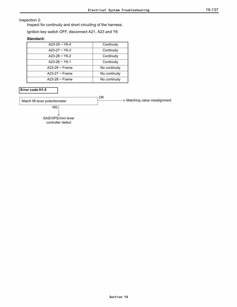
19-137
Inspection 2: Inspect for continuity and short circuiting of the harness.
Ignition key switch OFF, disconnect A21, A23 and Y6
Standard:A23-29 ~ Y6-4 Continuity
A23-27 ~ Y6-3 Continuity
A23-28 ~ Y6-2 Continuity
A23-26 ~ Y6-1 Continuity
A23-29 ~ Frame No continuity
A23-27 ~ Frame No continuity
A23-28 ~ Frame No continuity
Error code H1-5
OKMatching value misalignmentMatch lift lever potentiometer
NG
SAS/OPS/mini levercontroller defect
Electrical System Troubleshooting
Section 19
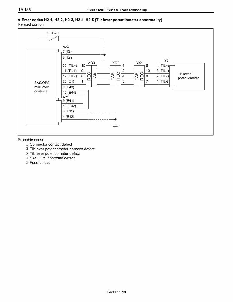
19-13819-138
Error codes H2-1, H2-2, H2-3, H2-4, H2-5 (Tilt lever potentiometer abnormality)Related portion
Probable cause Connector contact defect Tilt lever potentiometer harness defect Tilt lever potentiometer defect SAS/OPS controller defect Fuse defect
RE
C
TA
B
TA
B
RE
C
RE
C
TA
B Tilt leverpotentiometer
A237 (IG)
8 (IG2)
30 (TIL+)11 (TIL1)12 (TIL2)26 (E1)
9 (E43)10 (E44)
9 (E41)10 (E42)3 (E11)4 (E12)
Y5
SAS/OPS/mini levercontroller
4 (TIL+)3 (TIL1)2 (TIL2)1 (TIL-)
A21
ECU-IG
AO3 YX161087
15981
243
1XO2
Electrical System Troubleshooting
Section 19
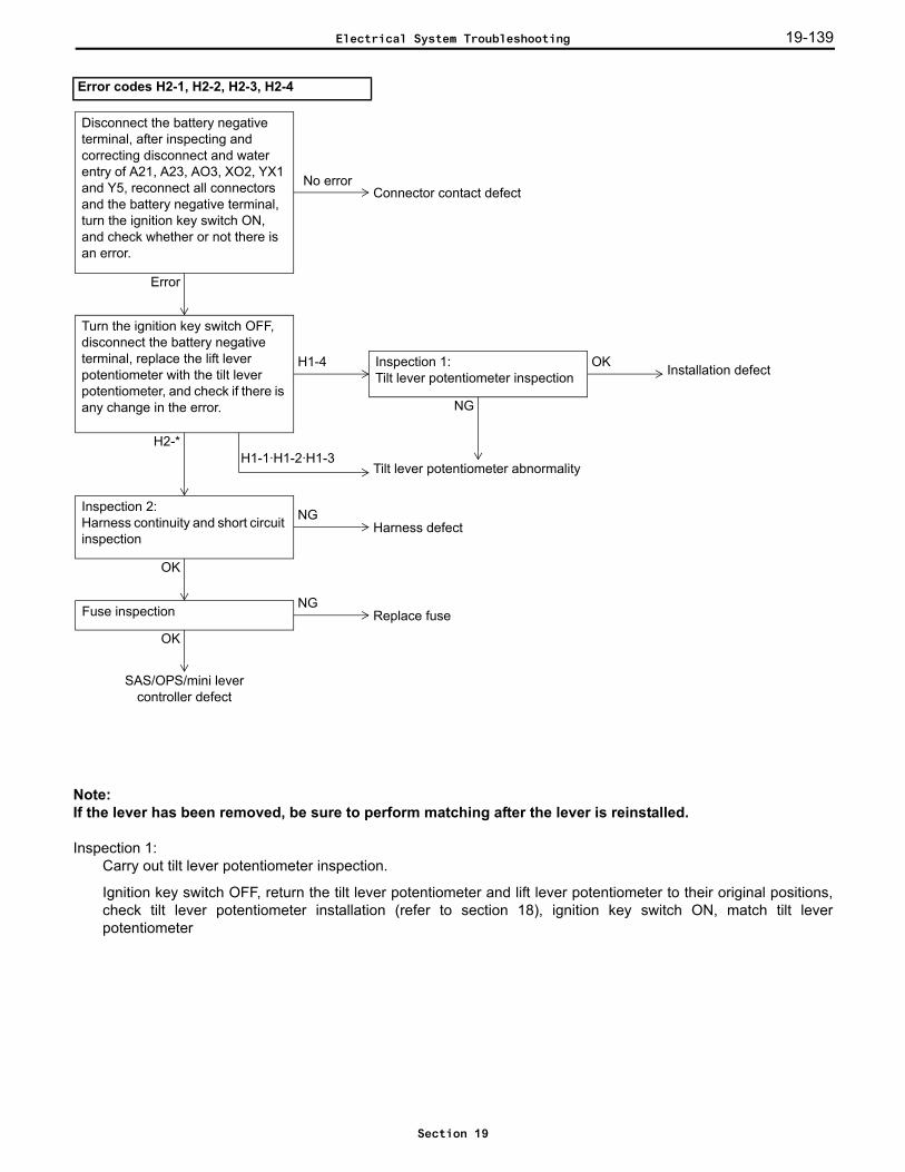
19-139
Note:If the lever has been removed, be sure to perform matching after the lever is reinstalled.
Inspection 1: Carry out tilt lever potentiometer inspection.
Ignition key switch OFF, return the tilt lever potentiometer and lift lever potentiometer to their original positions,check tilt lever potentiometer installation (refer to section 18), ignition key switch ON, match tilt leverpotentiometer
Error codes H2-1, H2-2, H2-3, H2-4
Turn the ignition key switch OFF, disconnect the battery negative terminal, replace the lift lever potentiometer with the tilt lever potentiometer, and check if there is any change in the error.
H2-*
H1-4 OKInspection 1:Tilt lever potentiometer inspection
NG
Installation defect
Tilt lever potentiometer abnormalityH1-1·H1-2·H1-3
Inspection 2:Harness continuity and short circuit inspection
NG
OK
Harness defect
Fuse inspection
OK
Replace fuseNG
SAS/OPS/mini levercontroller defect
No error
Error
Connector contact defect
Disconnect the battery negative terminal, after inspecting and correcting disconnect and water entry of A21, A23, AO3, XO2, YX1 and Y5, reconnect all connectors and the battery negative terminal, turn the ignition key switch ON, and check whether or not there is an error.
Electrical System Troubleshooting
Section 19

19-14019-140
Inspection 2: Inspect for continuity and short circuiting of the harness.
Ignition key switch OFF, disconnect A21, A23 and Y5
Standard:A23-30 ~ Y5-4 Continuity
A23-11 ~ Y5-3 Continuity
A23-12 ~ Y5-2 Continuity
A23-26 ~ Y5-1 Continuity
A23-30 ~ Frame No continuity
A23-11 ~ Frame No continuity
A23-12 ~ Frame No continuity
Error code H2-5
OKMatching value misalignmentMatch tilt lever potentiometer
NG
SAS/OPS/mini levercontroller defect
Electrical System Troubleshooting
Section 19

19-141
Error codes H3-1, H3-2, H3-3, H3-4, H3-5 (Attachment 1 lever potentiometer abnormality)Related portion
Probable cause Connector contact defect Attachment 1 lever potentiometer harness defect Attachment 1 lever potentiometer defect SAS/OPS controller defect Fuse defect
RE
C
TA
B
TA
B
RE
C
RE
C
TA
B Attachment 1 lever potentiometer
A237 (IG)
8 (IG2)
31 (AT1+)13 (AT11)14 (AT12)26 (E1)
9 (E43)10 (E44)
9 (E41)10 (E42)3 (E11)4 (E12)
Y2
SAS/OPS/mini levercontroller
4 (AT1+)3 (AT11)2 (AT12)1 (AT1-)
A21
ECU-IG
AO3 YX11315167
7651
563
10XO2
Electrical System Troubleshooting
Section 19
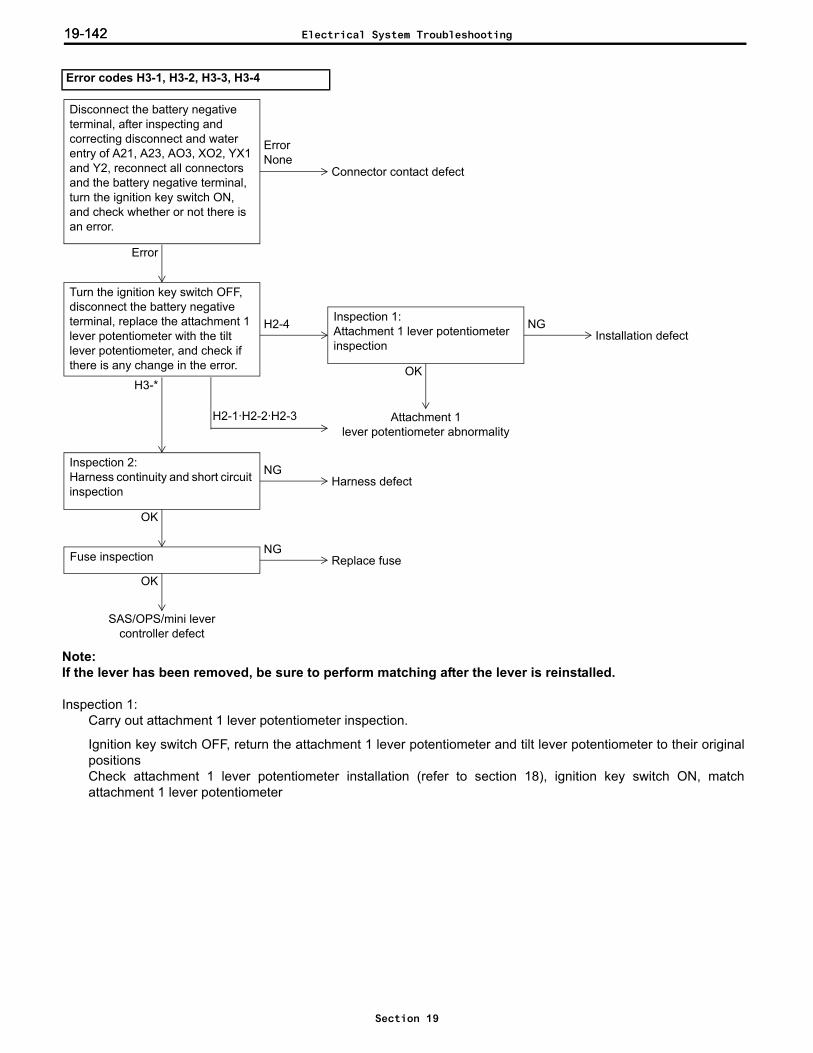
19-14219-142
Note:If the lever has been removed, be sure to perform matching after the lever is reinstalled.
Inspection 1: Carry out attachment 1 lever potentiometer inspection.
Ignition key switch OFF, return the attachment 1 lever potentiometer and tilt lever potentiometer to their originalpositionsCheck attachment 1 lever potentiometer installation (refer to section 18), ignition key switch ON, matchattachment 1 lever potentiometer
Error codes H3-1, H3-2, H3-3, H3-4
Turn the ignition key switch OFF, disconnect the battery negative terminal, replace the attachment 1 lever potentiometer with the tilt lever potentiometer, and check if there is any change in the error.
H3-*
H2-4Installation defect
Attachment 1lever potentiometer abnormality
H2-1·H2-2·H2-3
Inspection 2:Harness continuity and short circuit inspection
NG
OK
Harness defect
Fuse inspection
OK
Replace fuseNG
SAS/OPS/mini levercontroller defect
Inspection 1:Attachment 1 lever potentiometer inspection
NG
OK
ErrorNone
Error
Connector contact defect
Disconnect the battery negative terminal, after inspecting and correcting disconnect and water entry of A21, A23, AO3, XO2, YX1 and Y2, reconnect all connectors and the battery negative terminal, turn the ignition key switch ON, and check whether or not there is an error.
Electrical System Troubleshooting
Section 19

19-143
Inspection 2: Inspect for continuity and short circuiting of the harness.
Ignition key switch OFF, disconnect A21, A23 and Y2Standard:
A23-31 ~ Y2-4 Continuity
A23-13 ~ Y2-3 Continuity
A23-14 ~ Y2-2 Continuity
A23-26 ~ Y2-1 Continuity
A23-31 ~ Frame No continuity
A23-13 ~ Frame No continuity
A23-14 ~ Frame No continuity
Error code H3-5
Match attachment 1 lever potentiometerOK
Matching value misalignment
NG
SAS/OPS/mini levercontroller defect
Electrical System Troubleshooting
Section 19
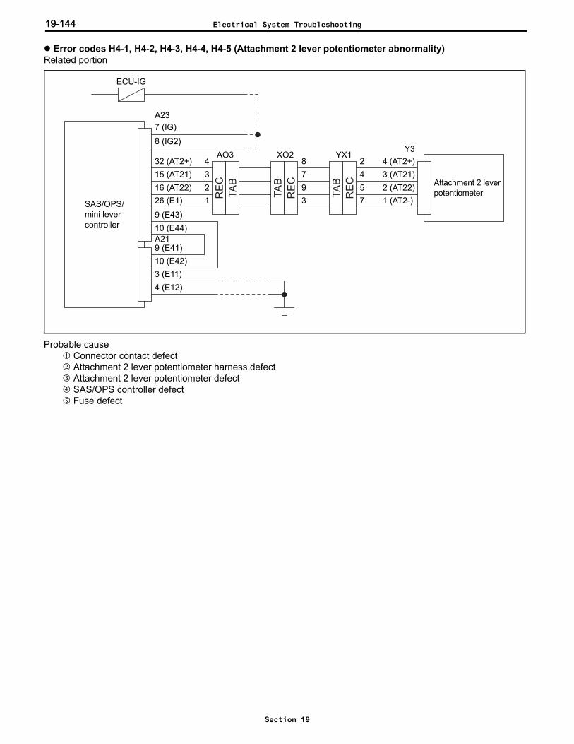
19-14419-144
Error codes H4-1, H4-2, H4-3, H4-4, H4-5 (Attachment 2 lever potentiometer abnormality)Related portion
Probable cause Connector contact defect Attachment 2 lever potentiometer harness defect Attachment 2 lever potentiometer defect SAS/OPS controller defect Fuse defect
RE
C
TA
B
TA
B
RE
C
RE
C
TA
B Attachment 2 leverpotentiometer
A237 (IG)
8 (IG2)
32 (AT2+)15 (AT21)16 (AT22)26 (E1)
9 (E43)10 (E44)
9 (E41)10 (E42)3 (E11)4 (E12)
Y3
SAS/OPS/mini levercontroller
4 (AT2+)3 (AT21)2 (AT22)1 (AT2-)
A21
ECU-IG
AO3 YX12457
4321
793
8XO2
Electrical System Troubleshooting
Section 19
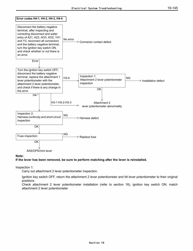
19-145
Note:If the lever has been removed, be sure to perform matching after the lever is reinstalled.
Inspection 1: Carry out attachment 2 lever potentiometer inspection.
Ignition key switch OFF, return the attachment 2 lever potentiometer and tilt lever potentiometer to their originalpositionsCheck attachment 2 lever potentiometer installation (refer to section 18), ignition key switch ON, matchattachment 2 lever potentiometer
Error codes H4-1, H4-2, H4-3, H4-4
Turn the ignition key switch OFF, disconnect the battery negative terminal, replace the attachment 1 lever potentiometer with the attachment 2 lever potentiometer, and check if there is any change in the error.
H4-*
H3-4Installation defect
Attachment 2lever potentiometer abnormality
H3-1·H3-2·H3-3
Inspection 2:Harness continuity and short circuit inspection
NG
OK
Harness defect
Fuse inspection
OK
Replace fuseNG
SAS/OPS/mini lever
Inspection 1:Attachment 2 lever potentiometer inspection
NG
OK
No error
Error
Connector contact defect
Disconnect the battery negative terminal, after inspecting and correcting disconnect and water entry of A21, A23, AO3, XO2, YX1 and Y3, reconnect all connectors and the battery negative terminal, turn the ignition key switch ON, and check whether or not there is an error.
Electrical System Troubleshooting
Section 19
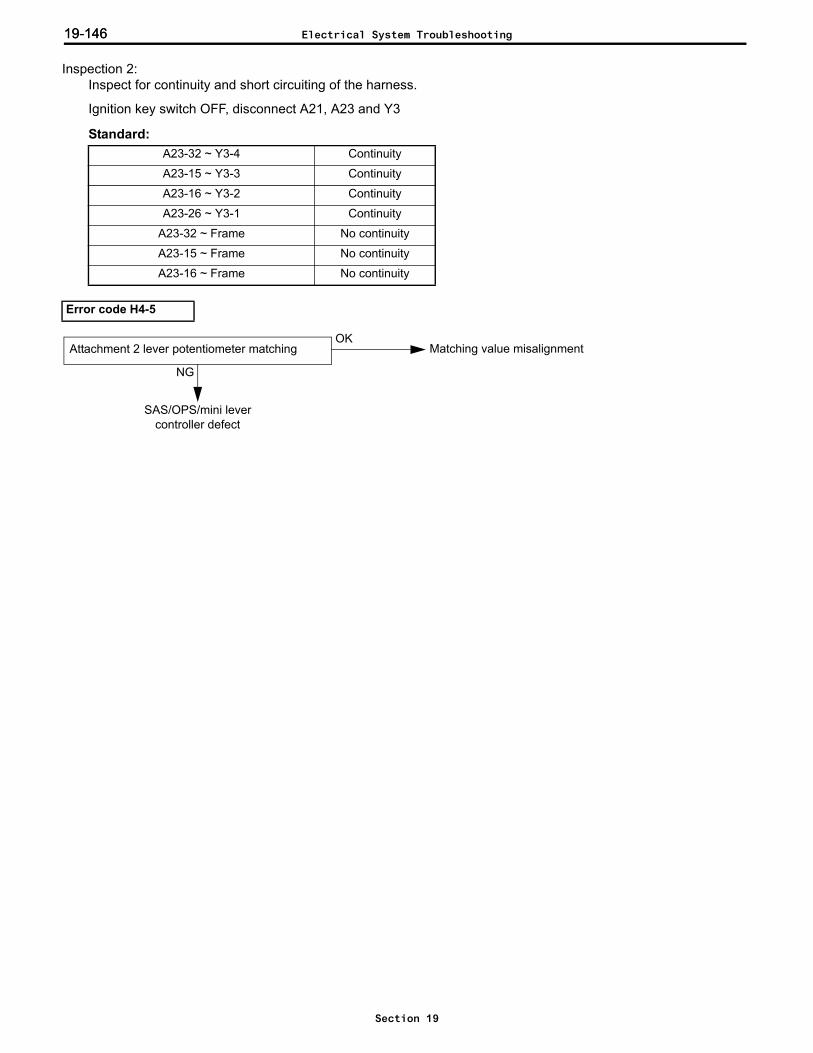
19-14619-146
Inspection 2: Inspect for continuity and short circuiting of the harness.
Ignition key switch OFF, disconnect A21, A23 and Y3
Standard:A23-32 ~ Y3-4 Continuity
A23-15 ~ Y3-3 Continuity
A23-16 ~ Y3-2 Continuity
A23-26 ~ Y3-1 Continuity
A23-32 ~ Frame No continuity
A23-15 ~ Frame No continuity
A23-16 ~ Frame No continuity
Error code H4-5
Attachment 2 lever potentiometer matchingOK
Matching value misalignment
NG
SAS/OPS/mini levercontroller defect
Electrical System Troubleshooting
Section 19

19-147
Error codes H5-1 and H5-2 (Lift solenoid abnormality)Related portion
Probable cause Connector contact defect Lift PULL solenoid harness defect Lift PUSH solenoid harness defect Lift PULL solenoid defect Lift PUSH solenoid defect SAS/OPS/mini lever controller defect
H5-1 is now described. For H5-2, substitute A52 for A51 and PULL for PUSH in the following.
Inspection 1: Carry out lift solenoid individual inspection.
Ignition key switch OFF, disconnect battery negative terminal, disconnect A51
Standard: (Solenoid side)
Error codes H5-1, H5-2
A51-5 ~ A51-1 Approx. 7 Ω (20°C)
SAS/OPS/mini levercontroller
A2317 (LSO+)18 (LPSH)
19 (LPLL)
A515 (LDS+)1 (LDS-)
A525 (LUS+)1 (LUS-)
Lift PUSHsolenoid
Lift PULLsolenoid
NGInspection 1:Lift solenoid individual inspection Lift PUSH solenoid defect
OK
NGInspection 2:Harness continuity and short circuit inspection Harness defect
OK
SAS/OPS mini lever controller defect
Error
No error
Disconnect the battery negative terminal, after inspecting and correcting disconnect and water entry of A23 and A51, reconnect all connectors and the battery negative terminal, turn the ignition key switch ON, operate the lift lever and check whether or not there is an error.
Connector contact defect
4321
8765
A51
Electrical System Troubleshooting
Section 19
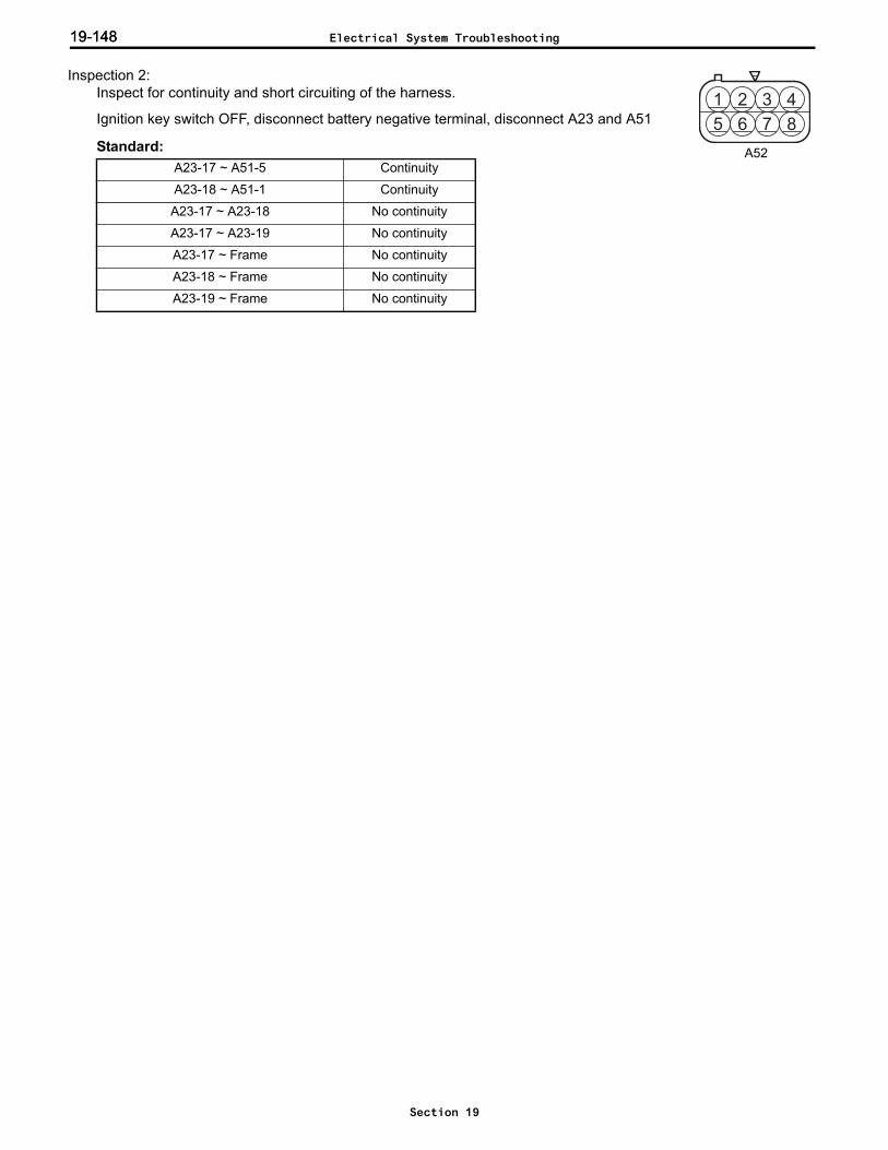
19-14819-148
Inspection 2: Inspect for continuity and short circuiting of the harness.
Ignition key switch OFF, disconnect battery negative terminal, disconnect A23 and A51
Standard:A23-17 ~ A51-5 Continuity
A23-18 ~ A51-1 Continuity
A23-17 ~ A23-18 No continuity
A23-17 ~ A23-19 No continuity
A23-17 ~ Frame No continuity
A23-18 ~ Frame No continuity
A23-19 ~ Frame No continuity
4321
8765
A52
Electrical System Troubleshooting
Section 19

19-149
Error codes H6-1 and H6-2 (Tilt solenoid abnormality)Related portion
Probable cause Connector contact defect Tilt PULL solenoid harness defect Tilt PUSH solenoid harness defect Tilt PULL solenoid defect Tilt PUSH solenoid defect SAS/OPS/mini lever controller defect
H6-1 is now described. For H6-2, substitute A52 for A51 and PULL for PUSH in the following
Inspection 1: Carry out tilt solenoid individual inspection.
Ignition key switch OFF, disconnect A51
Standard: (Solenoid side)
Error codes H6-1 and H6-2
A51-6 ~ A51-2 Approx. 7 Ω (20°C)
SAS/OPS/mini levercontroller
A231 (TSO+)2 (TPSH)
3 (TPLL)
A516 (TFS+)2 (TFS-)
A526 (TRS+)2 (TRS-)
Tilt PUSHsolenoid
Tilt PULLsolenoid
NGInspection 1:Tilt solenoid individual inspection Tilt PUSH solenoid defect
OK
NGInspection 2:Harness continuity and short circuit inspection Harness defect
OK
SAS/OPS mini lever controller defect
Error
No error
Disconnect the battery negative terminal, after inspecting and correcting disconnect A23 and A51 and water entry, reconnect all connectors and the battery negative terminal, turn the ignition key switch ON, operate the tilt lever and check whether or not there is an error.
Connector contact defect
4321
8765
A51
Electrical System Troubleshooting
Section 19

19-15019-150
Inspection 2: Inspect for continuity and short circuiting of the harness.
Ignition key switch OFF, disconnect A23 and A51
Standard:A23-1 ~ A51-6 Continuity
A23-2 ~ A51-2 Continuity
A23-1 ~ A23-2 No continuity
A23-1 ~ A23-3 No continuity
A23-1 ~ Frame No continuity
A23-2 ~ Frame No continuity
A23-3 ~ Frame No continuity
4321
8765
A52
Electrical System Troubleshooting
Section 19

19-151
Error codes H7-1, H7-2 (Attachment 1 solenoid abnormality)Related portion
Probable cause Connector contact defect Attachment 1 PUSH solenoid harness defect Attachment 1 PUSH solenoid defect Attachment 1 PULL solenoid harness defect Attachment 1 PULL solenoid defect SAS/OPS/ mini lever controller defect
H7-1 is now described. For H7-2, substitute A52 for A51 and PULL for PUSH in the following
Error codes H7-1, H7-2
SAS/OPS/mini levercontroller
A2320 (3SO+)21 (3PSH)
22 (3PLL)
A517 (3FS+)3 (3FS-)
A527 (3RS+)3 (3RS-)
Attachment 1PUSH solenoid
Attachment 1PULL solenoid
NGInspection 1:Attachment 1 solenoid individual inspection
Attachment 1 PUSHsolenoid defect
OK
NGInspection 2:Harness continuity and short circuit inspection Harness defect
OK
SAS/OPS mini lever controller defect
Error
No error
Disconnect the battery negative terminal, after inspecting and correcting disconnect and water entry of A23 and A51, reconnect all connectors and the battery negative terminal, turn the ignition key switch ON, operate attachment lever 1 and check whether or not there is an error.
Connector contact defect
Electrical System Troubleshooting
Section 19

19-15219-152
Inspection 1: Carry out attachment 1 solenoid individual inspection.
Ignition key switch OFF, disconnect A51
Standard: (Solenoid side)
Inspection 2: Inspect for continuity and short circuiting of the harness.
Ignition key switch OFF, disconnect A23 and A51
Standard:
A51-7 ~ A51-3 Approx. 7 Ω (20°C)
A23-20 ~ A51-7 Continuity
A23-21 ~ A51-3 Continuity
A23-20~ A23-21 No continuity
A23-20 ~ A23-22 No continuity
A23-20 ~ Frame No continuity
A23-21 ~ Frame No continuity
A23-22 ~ Frame No continuity
4321
8765
A51
4321
8765
A52
Electrical System Troubleshooting
Section 19
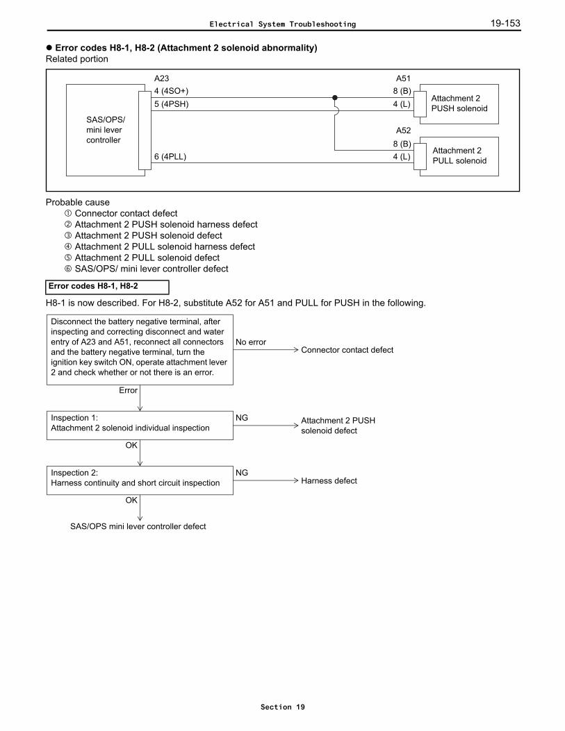
19-153
Error codes H8-1, H8-2 (Attachment 2 solenoid abnormality)Related portion
Probable cause Connector contact defect Attachment 2 PUSH solenoid harness defect Attachment 2 PUSH solenoid defect Attachment 2 PULL solenoid harness defect Attachment 2 PULL solenoid defect SAS/OPS/ mini lever controller defect
H8-1 is now described. For H8-2, substitute A52 for A51 and PULL for PUSH in the following.
Error codes H8-1, H8-2
SAS/OPS/mini levercontroller
A234 (4SO+)5 (4PSH)
6 (4PLL)
A518 (B)4 (L)
A528 (B)4 (L)
Attachment 2PUSH solenoid
Attachment 2PULL solenoid
NGInspection 1:Attachment 2 solenoid individual inspection
Attachment 2 PUSHsolenoid defect
OK
NGInspection 2:Harness continuity and short circuit inspection Harness defect
OK
SAS/OPS mini lever controller defect
Error
No error
Disconnect the battery negative terminal, after inspecting and correcting disconnect and water entry of A23 and A51, reconnect all connectors and the battery negative terminal, turn the ignition key switch ON, operate attachment lever 2 and check whether or not there is an error.
Connector contact defect
Electrical System Troubleshooting
Section 19

19-15419-154
Inspection 1: Carry out attachment 2 solenoid individual inspection.
Ignition key switch OFF, disconnect battery negative terminal and A51
Standard: (Solenoid side)
Inspection 2: Inspect for continuity and short circuiting of the harness.
Ignition key switch OFF, disconnect A23 and A51
Standard:
A51-8 ~ A51-4 Approx. 7 Ω (20°C)
A23-4 ~ A51-8 Continuity
A23-5 ~ A51-4 Continuity
A23-4 ~ A23-5 No continuity
A23-4 ~ A23-6 No continuity
A23-4 ~ Frame No continuity
A23-5 ~ Frame No continuity
A23-6 ~ Frame No continuity
4321
8765
A51
4321
8765
A52
Electrical System Troubleshooting
Section 19

19-155
Error code HA-1 (3/4-way change relay abnormality)Related portion
Probable cause Connector contact defect 3/4-way change relay 1 harness defect 3/4-way change relay 1 defect 3/4-way change relay 2 harness defect 3/4-way change relay 2 defect SAS/OPS controller defect
Inspection 1: Inspect for continuity and short circuiting of the harness.
Ignition key switch OFF, disconnect A21 and each relay
Standard:
Error code HA-1
A21-12 ~ Relay terminal 2 Continuity
A21-12 ~ Relay terminal 4 Continuity
A21-12 ~ Frame No continuity
IG
SAS/OPS/Mini lever controller
3/4-way change relay 1
3/4-way change relay 2
1 2
3 4
A21
12 (ATSO)
NGInspection 1:Harness continuity and short circuit inspection Harness defect
OK
SAS/OPS/mini lever controller defect
Error
No error
Disconnect the battery negative terminal, after inspecting and correcting disconnect and water entry of A21, reconnect A21 and the battery negative terminal (leave relay disconnected), turn the changeover switch to the 3-way side, turn the ignition key switch ON, and check whether or not there is an error.
3/4-way change relay defect
Electrical System Troubleshooting
Section 19

19-15619-156
TROUBLESHOOTING WHEN THERE IS NO ERROR CODE4Y-E Engine List by Symptom
Symptom Portion to be inspected Page for reference
Does not crank1. Starter relay and starter 19-157
2. Neutral start switch –
Cannot start (no starting combustion)
1. ECU power supply system 19-159
2. Igniter system 19-44
3. Fuel pump circuit 19-161
4. Fuel injector Refer to engine repair manual
Cannot start (no complete combustion)
1. Fuel pump circuit 19-161
2. Igniter system 19-44
3. Fuel injector Refer to engine repair manual
Does not start well
1. Electronic throttle Refer to engine repair manual
2. Fuel pump circuit 19-161
3. Igniter system 19-44
4. Spark plugs Refer to engine repair manual
5. Fuel injector Refer to engine repair manual
6. Compression Refer to engine repair manual
Fast idling rough 1. Electronic throttle Refer to engine repair manual
Idle speed high
1. Electronic throttle Refer to engine repair manual
2. ECU power supply system 19-159
3. Neutral start switch –
Idle speed low
1. Electronic throttle Refer to engine repair manual
2. Fuel injector Refer to engine repair manual
3. Igniter system 19-44
4. Compression Refer to engine repair manual
5. Fuel pump circuit 19-161
Idle unstable
1. Electronic throttle Refer to engine repair manual
2. ECU power supply system 19-159
3. Fuel pump circuit 19-161
Hunting
1. Fuel injector Refer to engine repair manual
2. Fuel pump circuit 19-161
3. Igniter system 19-44
Hesitation, poor acceleration
1. Igniter system 19-44
2. Spark plugs Refer to engine repair manual
3. Fuel injector Refer to engine repair manual
After fire
1. Fuel pump circuit 19-161
2. Spark plugs Refer to engine repair manual
3. Fuel injector Refer to engine repair manual
Engine stalling (immediately after start up)
1. Fuel pump circuit 19-161
Engine stalling (immediately after deceleration)
1. Fuel injector Refer to engine repair manual
2. Engine control computer –
Electrical System Troubleshooting
Section 19

19-157
Starter relay and starterRelated portion
Probable cause Neutral switch defect Starter relay defect Starter defect Wire harness, connector defect
Inspection 1: Carry out starter signal inspection.
Ignition key switch ONStarter signal (I/O motor: STA)
Standard:Starter stopped Starter in operation
STA 0 1
Ignition switch
to meter-related circuit Starter relay
Engine controller
Starter
Neutral switch
STA
G27-24 (STA)
51
32
AM1
OK
NG
Neutral switch defectStarter relay defect
Inspection 1:Starter signal inspectionANL.: I/O ENGINE CTRL 1/10
OKStarter defect
Inspection 2:Wire harness and connector inspection
NG
Wire harness, connector defect
Electrical System Troubleshooting
Section 19
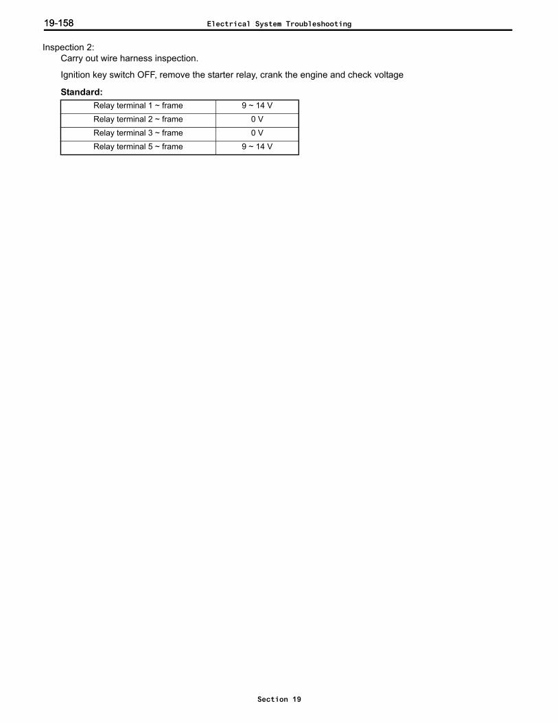
19-15819-158
Inspection 2: Carry out wire harness inspection.
Ignition key switch OFF, remove the starter relay, crank the engine and check voltage
Standard:Relay terminal 1 ~ frame 9 ~ 14 V
Relay terminal 2 ~ frame 0 V
Relay terminal 3 ~ frame 0 V
Relay terminal 5 ~ frame 9 ~ 14 V
Electrical System Troubleshooting
Section 19

19-159
ECU power supply systemRelated portion
Probable cause Blown fuse EFI main relay defect Wire harness, connector defect
Inspection 1: Carry out a fuse continuity inspection.
Remove the EFI fuse and IGN fuse.
Standard: Continuity exists.
Engine controller
EFI
EFI main relay
1 (+B)2 (+B1)
19 (MREL)
2 13
3 (BATT)A36
G281 (E02)2 (E01)
3 (E1)
G27
5
NGInspection 2:EFI main relay operation and continuity inspection
EFI main relay defect
OK
NGInspection 3:Harness continuity inspection Wire harness, connector defect
OK
Engine controller defect
NGInspection 1:EFI and IGN fuse inspection Replace fuse
OK
Electrical System Troubleshooting
Section 19
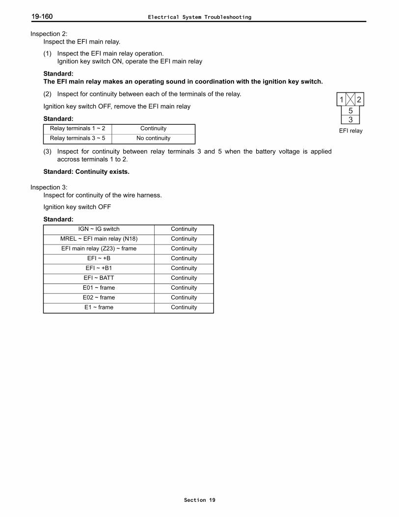
19-16019-160
Inspection 2: Inspect the EFI main relay.
(1) Inspect the EFI main relay operation.Ignition key switch ON, operate the EFI main relay
Standard: The EFI main relay makes an operating sound in coordination with the ignition key switch.
(2) Inspect for continuity between each of the terminals of the relay.
Ignition key switch OFF, remove the EFI main relay
Standard:
(3) Inspect for continuity between relay terminals 3 and 5 when the battery voltage is appliedaccross terminals 1 to 2.
Standard: Continuity exists.
Inspection 3: Inspect for continuity of the wire harness.
Ignition key switch OFF
Standard:
Relay terminals 1 ~ 2 Continuity
Relay terminals 3 ~ 5 No continuity
IGN ~ IG switch Continuity
MREL ~ EFI main relay (N18) Continuity
EFI main relay (Z23) ~ frame Continuity
EFI ~ +B Continuity
EFI ~ +B1 Continuity
EFI ~ BATT Continuity
E01 ~ frame Continuity
E02 ~ frame Continuity
E1 ~ frame Continuity
EFI relay
Electrical System Troubleshooting
Section 19

19-161
Fuel pump control systemRelated portion
Probable cause Blown fuse EFI main relay defect Wire harness, connector defect Fuel pump defect
Inspection 1: Carry out a fuse continuity inspection.
Remove the EFI fuse and IGN fuse.
Standard: Continuity exists.
TAB
RE
C
Enginecontroller
3 (GAS)Fuel changeover switch
1 (SOL)
EFI main relay
Fuel pump
22 (FC)
Circuit opening relay
1 25 3
2 (IG)
16
4
5
AO1
G28
2 13 5
G38
NGInspection 2:EFI main relay operation and continuity inspection EFI main relay defect
OK
NGInspection 3:Harness continuity inspection Wire harness, connector defect
OK
Fuel pump defect
NGInspection 1:Fuse inspection Replace fuse
OK
Electrical System Troubleshooting
Section 19
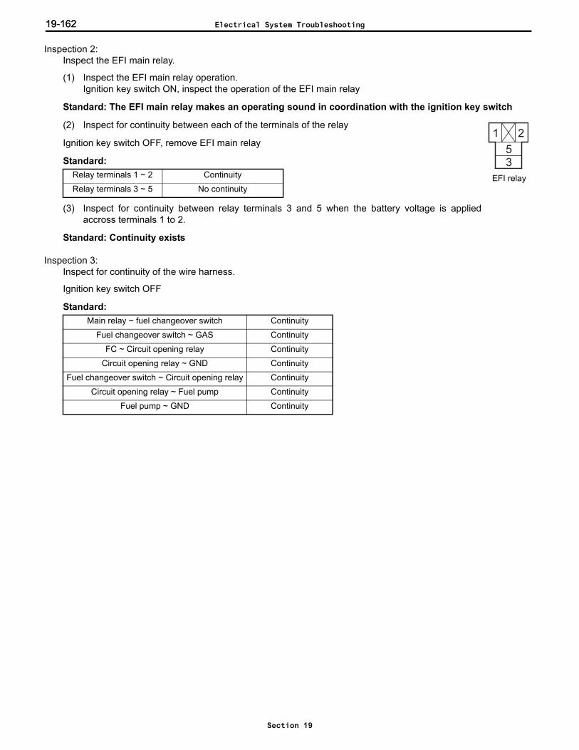
19-16219-162
Inspection 2: Inspect the EFI main relay.
(1) Inspect the EFI main relay operation.Ignition key switch ON, inspect the operation of the EFI main relay
Standard: The EFI main relay makes an operating sound in coordination with the ignition key switch
(2) Inspect for continuity between each of the terminals of the relay
Ignition key switch OFF, remove EFI main relay
Standard:
(3) Inspect for continuity between relay terminals 3 and 5 when the battery voltage is appliedaccross terminals 1 to 2.
Standard: Continuity exists
Inspection 3: Inspect for continuity of the wire harness.
Ignition key switch OFF
Standard:
Relay terminals 1 ~ 2 Continuity
Relay terminals 3 ~ 5 No continuity
Main relay ~ fuel changeover switch Continuity
Fuel changeover switch ~ GAS Continuity
FC ~ Circuit opening relay Continuity
Circuit opening relay ~ GND Continuity
Fuel changeover switch ~ Circuit opening relay Continuity
Circuit opening relay ~ Fuel pump Continuity
Fuel pump ~ GND Continuity
EFI relay
Electrical System Troubleshooting
Section 19

19-163
Def
ect C
ause
s W
hen
Ther
e is
No
SAS/
OPS
Err
or D
ispl
ay
Not
e:If
an e
rror
cod
e or
wre
nch
lam
p is
flas
hing
, rep
air i
t firs
t.C
ontro
l typ
ePh
enom
enon
on
vehi
cle
Mal
func
tion
area
· m
ode
Che
ckin
g m
etho
dC
orre
ctiv
e ac
tion
Trav
el a
nd lo
ad
hand
ling
cont
rol
For v
ehic
les
with
trav
el a
nd lo
ad
hand
ling
cont
rol:
Engi
ne is
alw
ays
slow
to re
v up
.(E
ven
with
the
dire
ctio
n le
ver l
eft i
n F
or R
pos
ition
and
the
brak
e ap
plie
d,
the
engi
ne is
stil
l slo
w to
rev
up)
Bra
ke s
witc
h un
it:
Ope
n fa
ult
(Stu
ck in
dep
ress
ed s
tate
, or
inte
rnal
dam
age)
Brak
e sw
itch
line:
D
isco
nnec
tion
faul
t(H
arne
ss, c
onne
ctor
, fus
e)
ON
/OFF
che
ck w
ith a
naly
zer
Har
ness
che
ck o
r rep
lace
sw
itch
Acc
eler
ator
sen
sor u
nit:
Inte
rnal
dam
age
Acce
lera
tor s
enso
r ins
talla
tion:
Li
nk, i
nsta
llatio
n pa
rt de
stro
yed,
da
mag
ed
Acce
lera
tor p
edal
pos
ition
che
ck:
Che
ck th
e op
enin
g de
gree
of t
he
acce
lera
tor p
edal
whe
n no
t ope
rate
d.
If no
t clo
se to
0%
, ins
talla
tion
chec
k or
re
plac
e se
nsor
.
SAS
/OP
S co
ntro
ller:
Con
trolle
r def
ect
–R
epla
ce
For v
ehic
les
with
trav
el a
nd lo
ad
hand
ling
cont
rol:
Eve
n if
the
lift i
s ra
ised
, the
idle
sp
eed
does
not
rise
.
Lift
rais
e sw
itch
unit:
Ope
n fa
ult
(Sw
itch
mou
nted
inco
rrect
ly,
inte
rnal
dam
age,
stu
ck)
Lift
rais
e sw
itch
line:
Dis
conn
ectio
n fa
ult
(Har
ness
, con
nect
or)
Switc
h gr
ound
line
: D
isco
nnec
tion
faul
t(H
arne
ss, c
onne
ctor
)
ON
/OFF
che
ck w
ith a
naly
zer
Har
ness
che
ck o
r rep
lace
sw
itch
Dis
play
set
ting:
Lift
idle
up
disa
bled
, Id
le u
p sp
eed
tuni
ng v
alue
low
Che
ck s
ettin
gs w
ith o
ptio
n se
t and
tu
ning
Cha
nge
SAS
/OP
S co
ntro
ller:
Con
trolle
r def
ect
–R
epla
ce
Electrical System Troubleshooting
Section 19
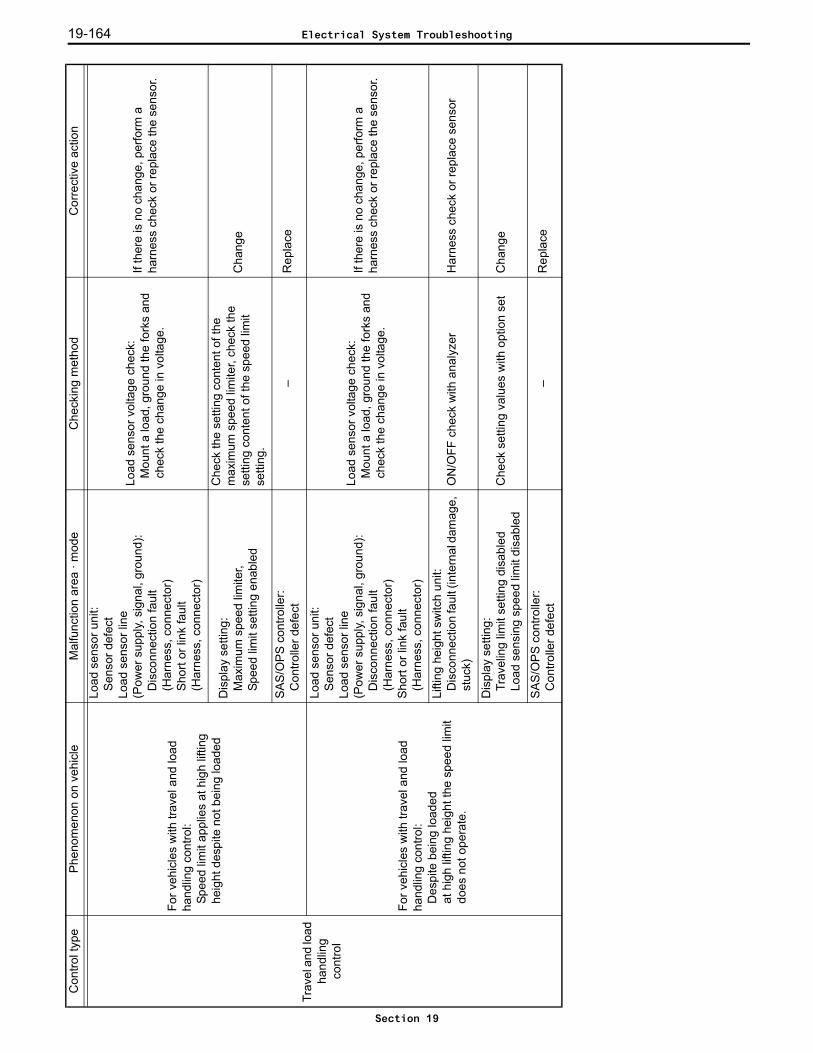
19-164
Trav
el a
nd lo
ad
hand
ling
cont
rol
For v
ehic
les
with
trav
el a
nd lo
ad
hand
ling
cont
rol:
Spee
d lim
it ap
plie
s at
hig
h lif
ting
heig
ht d
espi
te n
ot b
eing
load
ed
Load
sen
sor u
nit:
Sen
sor d
efec
tLo
ad s
enso
r lin
e(P
ower
sup
ply,
sig
nal,
grou
nd):
Dis
conn
ectio
n fa
ult
(Har
ness
, con
nect
or)
Shor
t or l
ink
faul
t(H
arne
ss, c
onne
ctor
)
Load
sen
sor v
olta
ge c
heck
:M
ount
a lo
ad, g
roun
d th
e fo
rks
and
chec
k th
e ch
ange
in v
olta
ge.
If th
ere
is n
o ch
ange
, per
form
a
harn
ess
chec
k or
repl
ace
the
sens
or.
Dis
play
set
ting:
Max
imum
spe
ed li
mite
r,Sp
eed
limit
setti
ng e
nabl
ed
Che
ck th
e se
tting
con
tent
of t
he
max
imum
spe
ed li
mite
r, ch
eck
the
setti
ng c
onte
nt o
f the
spe
ed li
mit
setti
ng.
Cha
nge
SAS
/OP
S co
ntro
ller:
Con
trolle
r def
ect
–R
epla
ce
For v
ehic
les
with
trav
el a
nd lo
ad
hand
ling
cont
rol:
Des
pite
bei
ng lo
aded
at
hig
h lif
ting
heig
ht th
e sp
eed
limit
does
not
ope
rate
.
Load
sen
sor u
nit:
Sen
sor d
efec
tLo
ad s
enso
r lin
e(P
ower
sup
ply,
sig
nal,
grou
nd):
Dis
conn
ectio
n fa
ult
(Har
ness
, con
nect
or)
Sho
rt or
link
faul
t(H
arne
ss, c
onne
ctor
)
Load
sen
sor v
olta
ge c
heck
:M
ount
a lo
ad, g
roun
d th
e fo
rks
and
chec
k th
e ch
ange
in v
olta
ge.
If th
ere
is n
o ch
ange
, per
form
a
harn
ess
chec
k or
repl
ace
the
sens
or.
Lifti
ng h
eigh
t sw
itch
unit:
D
isco
nnec
tion
faul
t (in
tern
al d
amag
e,
stuc
k)O
N/O
FF c
heck
with
ana
lyze
rH
arne
ss c
heck
or r
epla
ce s
enso
r
Dis
play
set
ting:
Trav
elin
g lim
it se
tting
dis
able
dLo
ad s
ensi
ng s
peed
lim
it di
sabl
edC
heck
set
ting
valu
es w
ith o
ptio
n se
tC
hang
e
SAS
/OP
S co
ntro
ller:
Con
trolle
r def
ect
–R
epla
ce
Con
trol t
ype
Phen
omen
on o
n ve
hicl
eM
alfu
nctio
n ar
ea ·
mod
eC
heck
ing
met
hod
Cor
rect
ive
actio
n
Electrical System Troubleshooting
Section 19
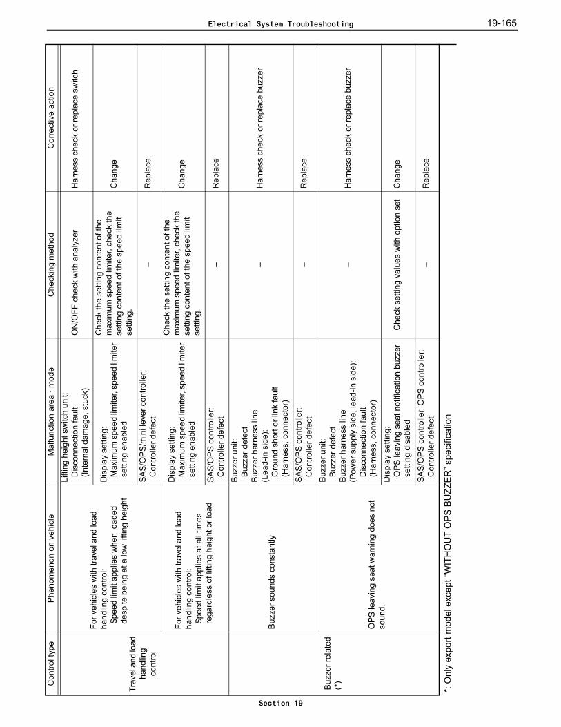
19-165
Trav
el a
nd lo
ad
hand
ling
cont
rol
For v
ehic
les
with
trav
el a
nd lo
ad
hand
ling
cont
rol:
Spee
d lim
it ap
plie
s w
hen
load
ed
desp
ite b
eing
at a
low
lifti
ng h
eigh
t
Lifti
ng h
eigh
t sw
itch
unit:
Dis
conn
ectio
n fa
ult
(Inte
rnal
dam
age,
stu
ck)
ON
/OFF
che
ck w
ith a
naly
zer
Har
ness
che
ck o
r rep
lace
sw
itch
Dis
play
set
ting:
Max
imum
spe
ed li
mite
r, sp
eed
limite
r se
tting
ena
bled
Che
ck th
e se
tting
con
tent
of t
he
max
imum
spe
ed li
mite
r, ch
eck
the
setti
ng c
onte
nt o
f the
spe
ed li
mit
setti
ng.
Cha
nge
SAS
/OP
S/m
ini l
ever
con
trolle
r:C
ontro
ller d
efec
t–
Rep
lace
For v
ehic
les
with
trav
el a
nd lo
ad
hand
ling
cont
rol:
Spee
d lim
it ap
plie
s at
all
times
re
gard
less
of l
iftin
g he
ight
or l
oad
Dis
play
set
ting:
Max
imum
spe
ed li
mite
r, sp
eed
limite
r se
tting
ena
bled
Che
ck th
e se
tting
con
tent
of t
he
max
imum
spe
ed li
mite
r, ch
eck
the
setti
ng c
onte
nt o
f the
spe
ed li
mit
setti
ng.
Cha
nge
SAS
/OP
S co
ntro
ller:
Con
trolle
r def
ect
–R
epla
ce
Buz
zer r
elat
ed
(*)
Buzz
er s
ound
s co
nsta
ntly
Buz
zer u
nit:
Buz
zer d
efec
tB
uzze
r har
ness
line
(Lea
d-in
sid
e):
Gro
und
shor
t or l
ink
faul
t (H
arne
ss, c
onne
ctor
)
–H
arne
ss c
heck
or r
epla
ce b
uzze
r
SAS
/OP
S co
ntro
ller:
Con
trolle
r def
ect
–R
epla
ce
OPS
leav
ing
seat
war
ning
doe
s no
t so
und.
Buz
zer u
nit:
Buz
zer d
efec
tB
uzze
r har
ness
line
(Pow
er s
uppl
y si
de, l
ead-
in s
ide)
:D
isco
nnec
tion
faul
t(H
arne
ss, c
onne
ctor
)
–H
arne
ss c
heck
or r
epla
ce b
uzze
r
Dis
play
set
ting:
OPS
leav
ing
seat
not
ifica
tion
buzz
er
setti
ng d
isab
led
Che
ck s
ettin
g va
lues
with
opt
ion
set
Cha
nge
SAS
/OP
S co
ntro
ller,
OP
S co
ntro
ller:
Con
trolle
r def
ect
–R
epla
ce
*: O
nly
expo
rt m
odel
exc
ept “
WIT
HO
UT
OP
S B
UZZ
ER
” spe
cific
atio
n
Con
trol t
ype
Phen
omen
on o
n ve
hicl
eM
alfu
nctio
n ar
ea ·
mod
eC
heck
ing
met
hod
Cor
rect
ive
actio
n
Electrical System Troubleshooting
Section 19
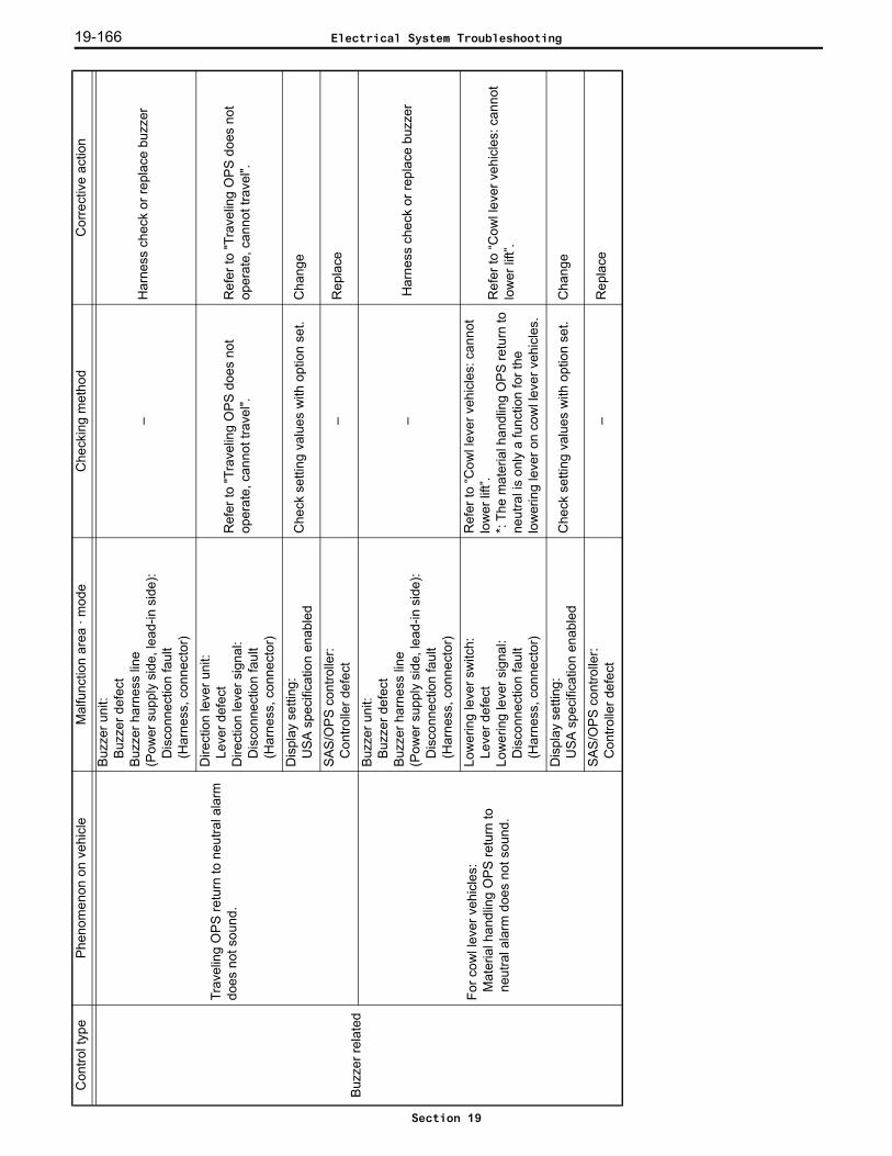
19-166
Buz
zer r
elat
ed
Trav
elin
g O
PS
retu
rn to
neu
tral a
larm
do
es n
ot s
ound
.
Buz
zer u
nit:
Buz
zer d
efec
tB
uzze
r har
ness
line
(Pow
er s
uppl
y si
de, l
ead-
in s
ide)
:D
isco
nnec
tion
faul
t(H
arne
ss, c
onne
ctor
)
–H
arne
ss c
heck
or r
epla
ce b
uzze
r
Dire
ctio
n le
ver u
nit:
Leve
r def
ect
Dire
ctio
n le
ver s
igna
l: D
isco
nnec
tion
faul
t(H
arne
ss, c
onne
ctor
)
Ref
er to
"Tra
velin
g O
PS d
oes
not
oper
ate,
can
not t
rave
l".R
efer
to "T
rave
ling
OP
S d
oes
not
oper
ate,
can
not t
rave
l".
Dis
play
set
ting:
USA
spe
cific
atio
n en
able
dC
heck
set
ting
valu
es w
ith o
ptio
n se
t.C
hang
e
SAS
/OP
S co
ntro
ller:
Con
trolle
r def
ect
–R
epla
ce
For c
owl l
ever
veh
icle
s:
Mat
eria
l han
dlin
g O
PS re
turn
to
neut
ral a
larm
doe
s no
t sou
nd.
Buz
zer u
nit:
Buz
zer d
efec
tB
uzze
r har
ness
line
(Pow
er s
uppl
y si
de, l
ead-
in s
ide)
:D
isco
nnec
tion
faul
t(H
arne
ss, c
onne
ctor
)
– H
arne
ss c
heck
or r
epla
ce b
uzze
r
Low
erin
g le
ver s
witc
h:
Leve
r def
ect
Low
erin
g le
ver s
igna
l: D
isco
nnec
tion
faul
t(H
arne
ss, c
onne
ctor
)
Ref
er to
“Cow
l lev
er v
ehic
les:
can
not
low
er li
ft”.
*: Th
e m
ater
ial h
andl
ing
OPS
retu
rn to
ne
utra
l is
only
a fu
nctio
n fo
r the
lo
wer
ing
leve
r on
cow
l lev
er v
ehic
les.
Ref
er to
“Cow
l lev
er v
ehic
les:
can
not
low
er li
ft”.
Dis
play
set
ting:
USA
spe
cific
atio
n en
able
dC
heck
set
ting
valu
es w
ith o
ptio
n se
t.C
hang
e
SAS
/OP
S co
ntro
ller:
Con
trolle
r def
ect
–R
epla
ce
Con
trol t
ype
Phen
omen
on o
n ve
hicl
eM
alfu
nctio
n ar
ea ·
mod
eC
heck
ing
met
hod
Cor
rect
ive
actio
n
Electrical System Troubleshooting
Section 19
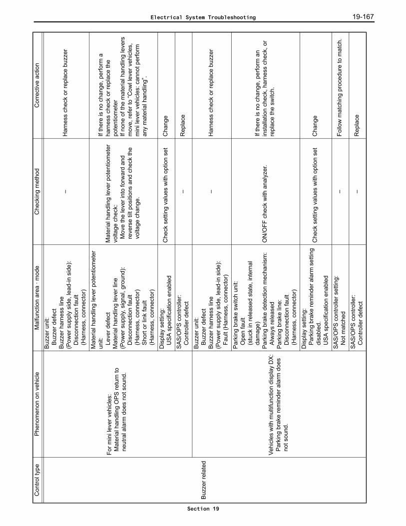
19-167
Buz
zer r
elat
ed
For m
ini l
ever
veh
icle
s:M
ater
ial h
andl
ing
OPS
retu
rn to
ne
utra
l ala
rm d
oes
not s
ound
.
Buz
zer u
nit:
Buz
zer d
efec
tB
uzze
r har
ness
line
(Pow
er s
uppl
y si
de, l
ead-
in s
ide)
:D
isco
nnec
tion
faul
t(H
arne
ss, c
onne
ctor
)
–H
arne
ss c
heck
or r
epla
ce b
uzze
r
Mat
eria
l han
dlin
g le
ver p
oten
tiom
eter
un
it: Leve
r def
ect
Mat
eria
l han
dlin
g le
ver l
ine
(Pow
er s
uppl
y, s
igna
l, gr
ound
):D
isco
nnec
tion
faul
t(H
arne
ss, c
onne
ctor
)Sh
ort o
r lin
k fa
ult
(Har
ness
, con
nect
or)
Mat
eria
l han
dlin
g le
ver p
oten
tiom
eter
vo
ltage
che
ck:
Mov
e th
e le
ver i
nto
forw
ard
and
reve
rse
tilt p
ositi
ons
and
chec
k th
e vo
ltage
cha
nge.
If th
ere
is n
o ch
ange
, per
form
a
harn
ess
chec
k or
repl
ace
the
pote
ntio
met
erIf
none
of t
he m
ater
ial h
andl
ing
leve
rs
mov
e, re
fer t
o “C
owl l
ever
veh
icle
s,
min
i lev
er v
ehic
les:
can
not p
erfo
rm
any
mat
eria
l han
dlin
g”.
Dis
play
set
ting:
USA
spe
cific
atio
n en
able
dC
heck
set
ting
valu
es w
ith o
ptio
n se
tC
hang
e
SAS
/OP
S co
ntro
ller:
Con
trolle
r def
ect
–R
epla
ce
Vehi
cles
with
mul
tifun
ctio
n di
spla
y D
X:
Park
ing
brak
e re
min
der a
larm
doe
s no
t sou
nd.
Buz
zer u
nit:
Buz
zer d
efec
tB
uzze
r har
ness
line
(Pow
er s
uppl
y si
de, l
ead-
in s
ide)
:Fa
ult (
Har
ness
, con
nect
or)
–H
arne
ss c
heck
or r
epla
ce b
uzze
r
Park
ing
brak
e sw
itch
unit:
Ope
n fa
ult
(stu
ck in
rele
ased
sta
te, i
nter
nal
dam
age)
Park
ing
brak
e de
tect
ion
mec
hani
sm:
Alw
ays
rele
ased
Park
ing
brak
e lin
e:
Dis
conn
ectio
n fa
ult
(Har
ness
, con
nect
or)
ON
/OFF
che
ck w
ith a
naly
zer.
If th
ere
is n
o ch
ange
, per
form
an
inst
alla
tion
chec
k, h
arne
ss c
heck
, or
repl
ace
the
switc
h.
Dis
play
set
ting:
Park
ing
brak
e re
min
der a
larm
set
ting
disa
bled
.U
SA s
peci
ficat
ion
enab
led
Che
ck s
ettin
g va
lues
with
opt
ion
set
Cha
nge
SAS
/OP
S co
ntro
ller s
ettin
g:
Not
mat
ched
–Fo
llow
mat
chin
g pr
oced
ure
to m
atch
.
SAS
/OP
S co
ntro
ller:
Con
trolle
r def
ect
–R
epla
ce
Con
trol t
ype
Phen
omen
on o
n ve
hicl
eM
alfu
nctio
n ar
ea ·
mod
eC
heck
ing
met
hod
Cor
rect
ive
actio
n
Electrical System Troubleshooting
Section 19
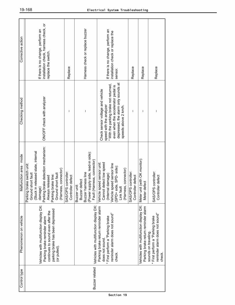
19-168
Buz
zer r
elat
ed
Vehi
cles
with
mul
tifun
ctio
n di
spla
y D
X:P
arki
ng b
rake
rem
inde
r ala
rm
cont
inue
s to
sou
nd e
ven
afte
r the
pa
rkin
g br
ake
has
been
dep
ress
ed
(or p
ulle
d).
Park
ing
brak
e sw
itch
unit:
Gro
und
shor
t fau
lt(S
tuck
in re
leas
ed s
tate
, int
erna
l da
mag
e)Pa
rkin
g br
ake
dete
ctio
n m
echa
nism
:Al
way
s re
leas
edPa
rkin
g br
ake
line:
Gro
und
shor
t fau
lt(H
arne
ss, c
onne
ctor
)
ON
/OFF
che
ck w
ith a
naly
zer
If th
ere
is n
o ch
ange
, per
form
an
inst
alla
tion
chec
k, h
arne
ss c
heck
, or
repl
ace
the
switc
h.
SAS
/OP
S co
ntro
ller:
Con
trolle
r def
ect
–R
epla
ce
Vehi
cles
with
mul
tifun
ctio
n di
spla
y D
X:P
arki
ng b
rake
retu
rn re
min
der a
larm
do
es n
ot s
ound
.*
Firs
t per
form
a “P
arki
ng b
rake
re
min
der a
larm
doe
s no
t sou
nd”
chec
k.
Buz
zer u
nit:
Buz
zer d
efec
tB
uzze
r har
ness
line
(Pow
er s
uppl
y si
de, l
ead-
in s
ide)
:Fa
ult (
Har
ness
, con
nect
or)
–H
arne
ss c
heck
or r
epla
ce b
uzze
r
Vehi
cle
spee
d se
nsor
uni
t:C
anno
t det
ect l
ow s
peed
(In
tern
al d
amag
e)Ve
hicl
e sp
eed
sens
or li
ne(S
PD
+ si
de, S
PD- s
ide)
: Li
nk fa
ult
(Har
ness
, con
nect
or)
Che
ck s
enso
r vol
tage
and
veh
icle
sp
eed
with
the
anal
yzer
*With
the
park
ing
brak
e no
t ret
urne
d,
even
whe
n th
e ac
cele
rato
r ped
al is
de
pres
sed,
the
alar
m o
nly
soun
ds a
t sp
eeds
abo
ve 2
km/h
.
If th
ere
is n
o ch
ange
, per
form
an
inst
alla
tion
chec
k or
repl
ace
the
sens
or.
SAS
/OP
S co
ntro
ller:
Con
trolle
r def
ect
–R
epla
ce
Vehi
cles
with
mul
tifun
ctio
n di
spla
y D
X:P
arki
ng b
rake
retu
rn re
min
der a
larm
so
unds
on
trave
ling.
* Fi
rst p
erfo
rm a
“Par
king
bra
ke
rem
inde
r ala
rm d
oes
not s
ound
” ch
eck.
Met
er u
nit (
with
OK
mon
itor)
:M
eter
def
ect
–R
epla
ce
SAS
/OP
S co
ntro
ller:
Con
trolle
r def
ect
–R
epla
ce
Con
trol t
ype
Phen
omen
on o
n ve
hicl
eM
alfu
nctio
n ar
ea ·
mod
eC
heck
ing
met
hod
Cor
rect
ive
actio
n
Electrical System Troubleshooting
Section 19

19-169
Dis
play
fu
nctio
n
Vehi
cles
with
mul
tifun
ctio
n di
spla
y D
X:W
hen
the
load
indi
cato
r sw
itch
is
pres
sed,
the
load
is n
ot d
ispl
ayed
.
Load
indi
cato
r sw
itch
unit:
Ope
n fa
ult (
Inte
rnal
dam
age)
Load
indi
cato
r sw
itch
dete
ctio
n m
echa
nism
(Min
i lev
er, j
oyst
ick)
: D
etec
tion
part
gap
adju
stm
ent d
efec
tLo
ad in
dica
tor s
witc
h lin
e(P
ower
sup
ply,
sig
nal,
grou
nd):
Ope
n fa
ult
(Pow
er s
uppl
y, h
arne
ss,
conn
ecto
r)
ON
/OFF
che
ck w
ith a
naly
zer
If th
ere
is n
o ch
ange
, per
form
an
inst
alla
tion
chec
k, h
arne
ss c
heck
, or
repl
ace
the
switc
h (le
ver).
Vehi
cles
with
mul
tifun
ctio
n di
spla
y D
X:W
hen
the
vehi
cle
is s
topp
ed, t
he
disp
lay
cont
inua
lly s
how
s lo
ad
indi
cato
r.
Load
indi
cato
r sw
itch
unit:
Shor
t fau
lt (In
tern
al d
amag
e)Lo
ad in
dica
tor s
witc
h de
tect
ion
mec
hani
sm (M
ini l
ever
, joy
stic
k):
Det
ectio
n pa
rt ga
p ad
just
men
t def
ect
Load
indi
cato
r sw
itch
line
(Sig
nal):
Sh
ort f
ault
(Har
ness
, con
nect
or)
ON
/OFF
che
ck w
ith a
naly
zer
If th
ere
is n
o ch
ange
, per
form
an
inst
alla
tion
chec
k, h
arne
ss c
heck
, or
repl
ace
the
switc
h (le
ver).
Vehi
cles
with
mul
tifun
ctio
n di
spla
y D
X:Th
e co
rrect
load
is n
ot d
ispl
ayed
.
Dis
play
set
ting:
Cyl
inde
r bor
e, n
umbe
r of c
ylin
ders
, 0
poin
t cor
rect
ion,
cal
ibra
tion
Car
ry o
ut re
mat
chin
g an
d ch
eck
oper
atio
nLo
ad s
enso
r vol
tage
che
ck:
Mou
nt a
load
, gro
und
the
fork
s an
d ch
eck
the
chan
ge in
vol
tage
*At h
igh
liftin
g he
ight
, cor
rect
load
ca
nnot
be
calc
ulat
ed a
nd th
e di
spla
y fla
shes
.
Follo
w th
e pr
oced
ure
for m
atch
ing,
an
d re
mat
ch (c
ylin
der b
ore,
num
ber o
f cy
linde
rs, 0
poi
nt c
orre
ctio
n)In
cas
es w
here
pre
cisi
on is
requ
ired,
ad
just
on
the
load
indi
cato
r mat
chin
g LO
AD
CA
LIB
RAT
ION
scr
een.
If th
ere
is n
o ch
ange
dur
ing
the
volta
ge
chec
k, p
erfo
rm a
har
ness
che
ck o
r re
plac
e th
e se
nsor
.
Con
trol t
ype
Phen
omen
on o
n ve
hicl
eM
alfu
nctio
n ar
ea ·
mod
eC
heck
ing
met
hod
Cor
rect
ive
actio
n
Electrical System Troubleshooting
Section 19
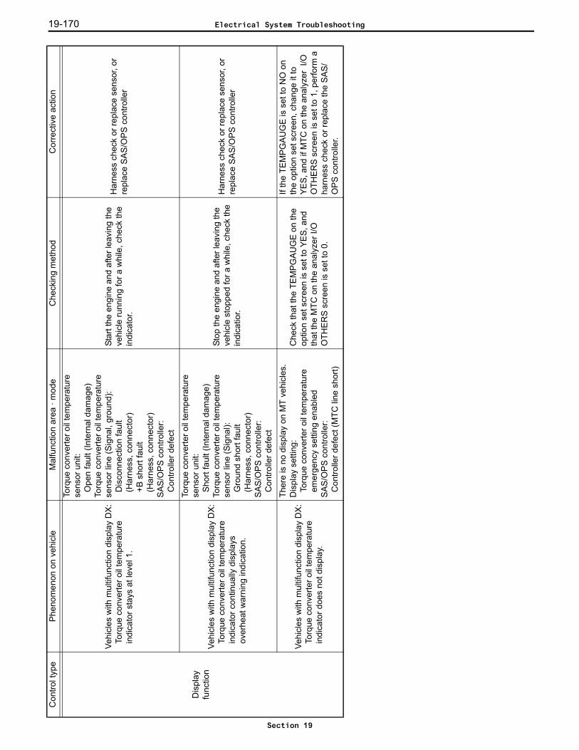
19-170
Dis
play
fu
nctio
n
Vehi
cles
with
mul
tifun
ctio
n di
spla
y D
X:To
rque
con
verte
r oil
tem
pera
ture
in
dica
tor s
tays
at l
evel
1.
Torq
ue c
onve
rter o
il te
mpe
ratu
re
sens
or u
nit:
Ope
n fa
ult (
Inte
rnal
dam
age)
Torq
ue c
onve
rter o
il te
mpe
ratu
re
sens
or li
ne (S
igna
l, gr
ound
):D
isco
nnec
tion
faul
t(H
arne
ss, c
onne
ctor
)+B
sho
rt fa
ult
(Har
ness
, con
nect
or)
SAS
/OP
S co
ntro
ller:
Con
trolle
r def
ect
Star
t the
eng
ine
and
afte
r lea
ving
the
vehi
cle
runn
ing
for a
whi
le, c
heck
the
indi
cato
r.
Har
ness
che
ck o
r rep
lace
sen
sor,
or
repl
ace
SA
S/O
PS
con
trolle
r
Vehi
cles
with
mul
tifun
ctio
n di
spla
y D
X:To
rque
con
verte
r oil
tem
pera
ture
in
dica
tor c
ontin
ually
dis
play
s ov
erhe
at w
arni
ng in
dica
tion.
Torq
ue c
onve
rter o
il te
mpe
ratu
re
sens
or u
nit:
Shor
t fau
lt (In
tern
al d
amag
e)To
rque
con
verte
r oil
tem
pera
ture
se
nsor
line
(Sig
nal):
G
roun
d sh
ort f
ault
(Har
ness
, con
nect
or)
SAS
/OP
S co
ntro
ller:
Con
trolle
r def
ect
Stop
the
engi
ne a
nd a
fter l
eavi
ng th
e ve
hicl
e st
oppe
d fo
r a w
hile
, che
ck th
e in
dica
tior.
Har
ness
che
ck o
r rep
lace
sen
sor,
or
repl
ace
SA
S/O
PS
con
trolle
r
Vehi
cles
with
mul
tifun
ctio
n di
spla
y D
X:To
rque
con
verte
r oil
tem
pera
ture
in
dica
tor d
oes
not d
ispl
ay.
Ther
e is
no
disp
lay
on M
T ve
hicl
es.
Dis
play
set
ting:
Torq
ue c
onve
rter o
il te
mpe
ratu
re
emer
genc
y se
tting
ena
bled
SAS
/OP
S co
ntro
ller:
Con
trolle
r def
ect (
MTC
line
sho
rt)
Che
ck th
at th
e TE
MP
GA
UG
E o
n th
e op
tion
set s
cree
n is
set
to Y
ES
, and
th
at th
e M
TC o
n th
e an
alyz
er I/
O
OTH
ER
S s
cree
n is
set
to 0
.
If th
e TE
MP
GA
UG
E is
set
to N
O o
n th
e op
tion
set s
cree
n, c
hang
e it
to
YE
S, a
nd if
MTC
on
the
anal
yzer
I/O
O
THER
S s
cree
n is
set
to 1
, per
form
a
harn
ess
chec
k or
repl
ace
the
SA
S/
OP
S c
ontro
ller.
Con
trol t
ype
Phen
omen
on o
n ve
hicl
eM
alfu
nctio
n ar
ea ·
mod
eC
heck
ing
met
hod
Cor
rect
ive
actio
n
Electrical System Troubleshooting
Section 19

19-171
Swin
g lo
ckFe
els
unst
able
whe
n tra
velin
g.(T
rave
ling
lock
has
bec
ome
diffi
cult
or
no lo
nger
pos
sibl
e)
Tire
uni
t:B
urst
, tire
pre
ssur
e ad
just
men
t de
fect
–A
djus
t or r
epla
ce
Lock
cyl
inde
r uni
t:Le
ak, c
anno
t loc
k(In
tern
al d
amag
e)Lo
ck c
ylin
der l
ocke
d st
atus
:In
stal
latio
n pa
rt da
mag
ed o
r de
stro
yed
Che
ck th
e lo
cked
sta
tus
with
an
activ
e te
st.
Rep
lace
Load
sen
sor u
nit:
Sen
sor d
efec
tLo
ad s
enso
r lin
e(P
ower
sup
ply,
sig
nal,
grou
nd):
Dis
conn
ectio
n fa
ult
(Har
ness
, con
nect
or)
Shor
t or l
eak
faul
t(H
arne
ss, c
onne
ctor
)
Load
sen
sor v
olta
ge c
heck
:P
efor
m li
ft re
lief a
nd c
heck
the
chan
ge in
vol
tage
.
If th
ere
is n
o ch
ange
, per
form
an
inst
alla
tion
chec
k or
repl
ace
the
sens
or.
Lifti
ng h
eigh
t sw
itch
unit:
Dis
conn
ectio
n fa
ult
(Inte
rnal
dam
age,
stu
ck)
ON
/OFF
che
ck w
ith a
naly
zer
Har
ness
che
ck o
r rep
lace
sw
itch
Yaw
rate
sen
sor u
nit:
Red
uced
sen
sitiv
ity, v
olta
ge s
tuck
(Inte
rnal
dam
age)
Yaw
rate
sen
sor l
ine
(Sig
nal):
Leak
(Har
ness
, con
nect
or)
Yaw
rate
sen
sor v
olta
ge c
heck
: C
heck
that
the
volta
ge is
ap
prox
imat
ely
2.5
V w
hen
the
vehi
cle
is s
topp
ed.
Inst
alla
tion
chec
k or
repl
ace
sens
or
Vehi
cle
spee
d se
nsor
uni
t:C
anno
t det
ect l
ow s
peed
s (In
tern
al d
amag
e)Ve
hicl
e sp
eed
sens
or li
ne(S
PD
+ si
de, S
PD- s
ide)
:Le
ak fa
ult
(Har
ness
, con
nect
or)
Che
ck s
enso
r vol
tage
and
veh
icle
sp
eed
with
the
anal
yzer
If th
ere
is n
o ch
ange
, per
form
an
inst
alla
tion
chec
k or
repl
ace
the
sens
or.
SAS
/OP
S co
ntro
ller:
Con
trolle
r def
ect
–R
epla
ce
Con
trol t
ype
Phen
omen
on o
n ve
hicl
eM
alfu
nctio
n ar
ea ·
mod
eC
heck
ing
met
hod
Cor
rect
ive
actio
n
Electrical System Troubleshooting
Section 19
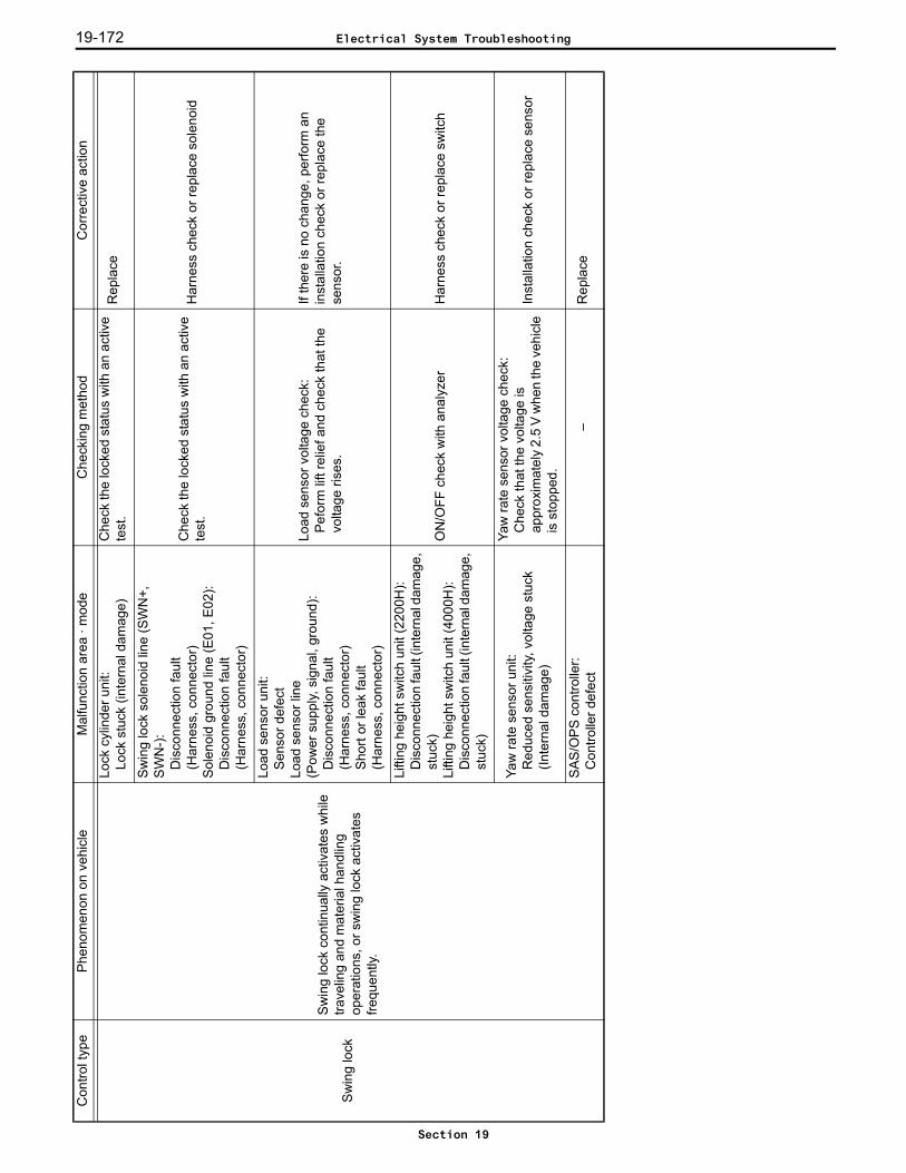
19-172
Swin
g lo
ck
Sw
ing
lock
con
tinua
lly a
ctiv
ates
whi
le
trave
ling
and
mat
eria
l han
dlin
g op
erat
ions
, or s
win
g lo
ck a
ctiv
ates
fre
quen
tly.
Lock
cyl
inde
r uni
t:Lo
ck s
tuck
(int
erna
l dam
age)
Che
ck th
e lo
cked
sta
tus
with
an
activ
e te
st.
Rep
lace
Swin
g lo
ck s
olen
oid
line
(SW
N+,
S
WN
-):
Dis
conn
ectio
n fa
ult
(Har
ness
, con
nect
or)
Sole
noid
gro
und
line
(E01
, E02
): D
isco
nnec
tion
faul
t(H
arne
ss, c
onne
ctor
)
Che
ck th
e lo
cked
sta
tus
with
an
activ
e te
st.
Har
ness
che
ck o
r rep
lace
sol
enoi
d
Load
sen
sor u
nit:
Sen
sor d
efec
tLo
ad s
enso
r lin
e(P
ower
sup
ply,
sig
nal,
grou
nd):
Dis
conn
ectio
n fa
ult
(Har
ness
, con
nect
or)
Shor
t or l
eak
faul
t(H
arne
ss, c
onne
ctor
)
Load
sen
sor v
olta
ge c
heck
:P
efor
m li
ft re
lief a
nd c
heck
that
the
volta
ge ri
ses.
If th
ere
is n
o ch
ange
, per
form
an
inst
alla
tion
chec
k or
repl
ace
the
sens
or.
Lifti
ng h
eigh
t sw
itch
unit
(220
0H):
Dis
conn
ectio
n fa
ult (
inte
rnal
dam
age,
st
uck)
Lifti
ng h
eigh
t sw
itch
unit
(400
0H):
Dis
conn
ectio
n fa
ult (
inte
rnal
dam
age,
st
uck)
ON
/OFF
che
ck w
ith a
naly
zer
Har
ness
che
ck o
r rep
lace
sw
itch
Yaw
rate
sen
sor u
nit:
Red
uced
sen
sitiv
ity, v
olta
ge s
tuck
(Inte
rnal
dam
age)
Yaw
rate
sen
sor v
olta
ge c
heck
:C
heck
that
the
volta
ge is
ap
prox
imat
ely
2.5
V w
hen
the
vehi
cle
is s
topp
ed.
Inst
alla
tion
chec
k or
repl
ace
sens
or
SAS
/OP
S co
ntro
ller:
Con
trolle
r def
ect
–R
epla
ce
Con
trol t
ype
Phen
omen
on o
n ve
hicl
eM
alfu
nctio
n ar
ea ·
mod
eC
heck
ing
met
hod
Cor
rect
ive
actio
n
Electrical System Troubleshooting
Section 19
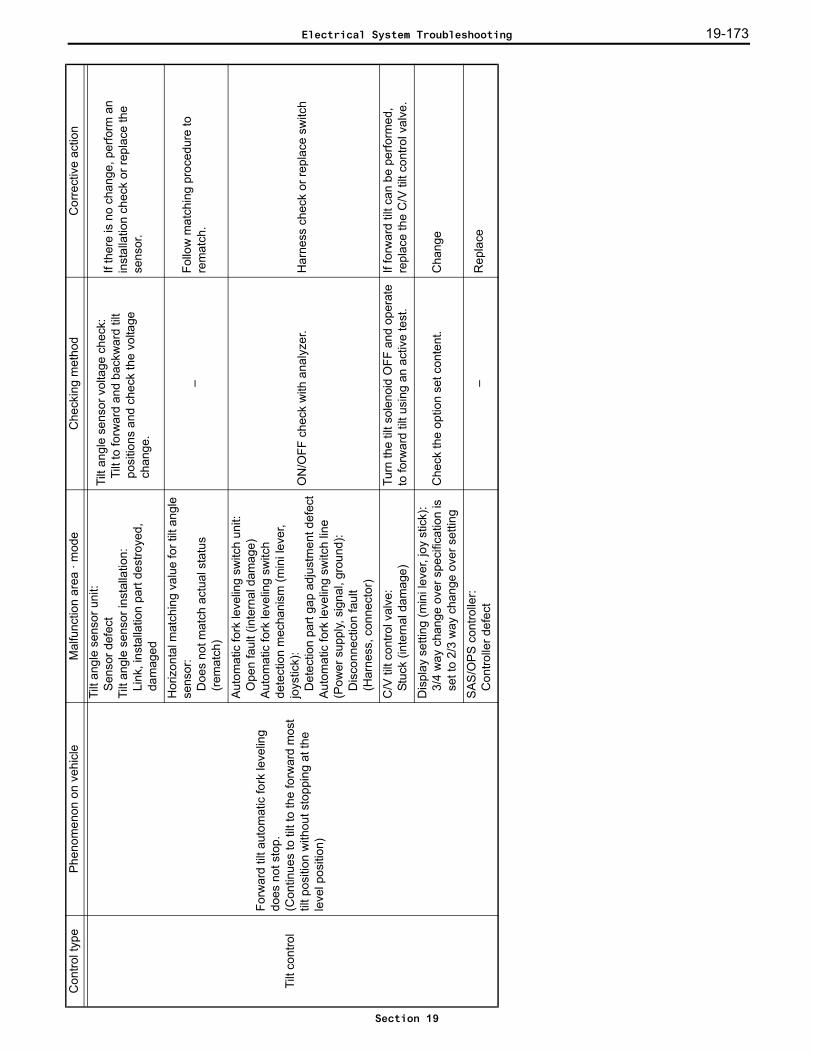
19-173
Tilt
cont
rol
Forw
ard
tilt a
utom
atic
fork
leve
ling
does
not
sto
p.(C
ontin
ues
to ti
lt to
the
forw
ard
mos
t til
t pos
ition
with
out s
topp
ing
at th
e le
vel p
ositi
on)
Tilt
angl
e se
nsor
uni
t:S
enso
r def
ect
Tilt
angl
e se
nsor
inst
alla
tion:
Link
, ins
talla
tion
part
dest
roye
d,
dam
aged
Tilt
angl
e se
nsor
vol
tage
che
ck:
Tilt
to fo
rwar
d an
d ba
ckw
ard
tilt
posi
tions
and
che
ck th
e vo
ltage
ch
ange
.
If th
ere
is n
o ch
ange
, per
form
an
inst
alla
tion
chec
k or
repl
ace
the
sens
or.
Hor
izon
tal m
atch
ing
valu
e fo
r tilt
ang
le
sens
or:
Doe
s no
t mat
ch a
ctua
l sta
tus
(rem
atch
)
–Fo
llow
mat
chin
g pr
oced
ure
to
rem
atch
.
Aut
omat
ic fo
rk le
velin
g sw
itch
unit:
Ope
n fa
ult (
inte
rnal
dam
age)
Aut
omat
ic fo
rk le
velin
g sw
itch
dete
ctio
n m
echa
nism
(min
i lev
er,
joys
tick)
:D
etec
tion
part
gap
adju
stm
ent d
efec
tA
utom
atic
fork
leve
ling
switc
h lin
e(P
ower
sup
ply,
sig
nal,
grou
nd):
Dis
conn
ectio
n fa
ult
(Har
ness
, con
nect
or)
ON
/OFF
che
ck w
ith a
naly
zer.
Har
ness
che
ck o
r rep
lace
sw
itch
C/V
tilt
cont
rol v
alve
:St
uck
(inte
rnal
dam
age)
Turn
the
tilt s
olen
oid
OFF
and
ope
rate
to
forw
ard
tilt u
sing
an
activ
e te
st.
If fo
rwar
d til
t can
be
perfo
rmed
, re
plac
e th
e C
/V ti
lt co
ntro
l val
ve.
Dis
play
set
ting
(min
i lev
er, j
oy s
tick)
: 3/
4 w
ay c
hang
e ov
er s
peci
ficat
ion
is
set t
o 2/
3 w
ay c
hang
e ov
er s
ettin
gC
heck
the
optio
n se
t con
tent
.C
hang
e
SAS
/OP
S co
ntro
ller:
Con
trolle
r def
ect
–R
epla
ce
Con
trol t
ype
Phen
omen
on o
n ve
hicl
eM
alfu
nctio
n ar
ea ·
mod
eC
heck
ing
met
hod
Cor
rect
ive
actio
n
Electrical System Troubleshooting
Section 19
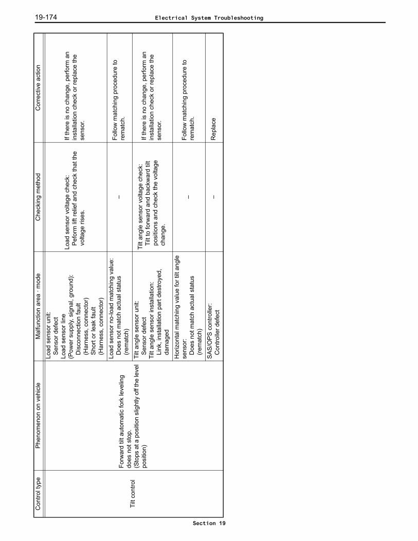
19-174
Tilt
cont
rol
Forw
ard
tilt a
utom
atic
fork
leve
ling
does
not
sto
p.(S
tops
at a
pos
ition
slig
htly
off
the
leve
l po
sitio
n)
Load
sen
sor u
nit:
Sen
sor d
efec
tLo
ad s
enso
r lin
e(P
ower
sup
ply,
sig
nal,
grou
nd):
Dis
conn
ectio
n fa
ult
(Har
ness
, con
nect
or)
Shor
t or l
eak
faul
t(H
arne
ss, c
onne
ctor
)
Load
sen
sor v
olta
ge c
heck
:P
efor
m li
ft re
lief a
nd c
heck
that
the
volta
ge ri
ses.
If th
ere
is n
o ch
ange
, per
form
an
inst
alla
tion
chec
k or
repl
ace
the
sens
or.
Load
sen
sor n
o-lo
ad m
atch
ing
valu
e:
Doe
s no
t mat
ch a
ctua
l sta
tus
(rem
atch
)–
Follo
w m
atch
ing
proc
edur
e to
re
mat
ch.
Tilt
angl
e se
nsor
uni
t:S
enso
r def
ect
Tilt
angl
e se
nsor
inst
alla
tion:
Link
, ins
talla
tion
part
dest
roye
d,
dam
aged
Tilt
angl
e se
nsor
vol
tage
che
ck:
Tilt
to fo
rwar
d an
d ba
ckw
ard
tilt
posi
tions
and
che
ck th
e vo
ltage
ch
ange
.
If th
ere
is n
o ch
ange
, per
form
an
inst
alla
tion
chec
k or
repl
ace
the
sens
or.
Hor
izon
tal m
atch
ing
valu
e fo
r tilt
ang
le
sens
or:
Doe
s no
t mat
ch a
ctua
l sta
tus
(rem
atch
)
–Fo
llow
mat
chin
g pr
oced
ure
to
rem
atch
.
SAS
/OP
S co
ntro
ller:
Con
trolle
r def
ect
–R
epla
ce
Con
trol t
ype
Phen
omen
on o
n ve
hicl
eM
alfu
nctio
n ar
ea ·
mod
eC
heck
ing
met
hod
Cor
rect
ive
actio
n
Electrical System Troubleshooting
Section 19
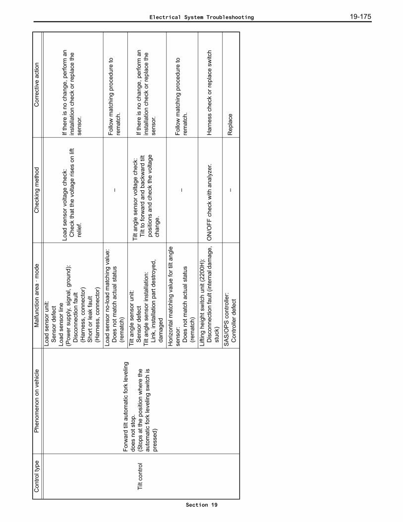
19-175
Tilt
cont
rol
Forw
ard
tilt a
utom
atic
fork
leve
ling
does
not
sto
p.(S
tops
at t
he p
ositi
on w
here
the
auto
mat
ic fo
rk le
velin
g sw
itch
is
pres
sed)
Load
sen
sor u
nit:
Sen
sor d
efec
tLo
ad s
enso
r lin
e(P
ower
sup
ply,
sig
nal,
grou
nd):
Dis
conn
ectio
n fa
ult
(Har
ness
, con
nect
or)
Shor
t or l
eak
faul
t(H
arne
ss, c
onne
ctor
)
Load
sen
sor v
olta
ge c
heck
:C
heck
that
the
volta
ge ri
ses
on li
ft re
lief.
If th
ere
is n
o ch
ange
, per
form
an
inst
alla
tion
chec
k or
repl
ace
the
sens
or.
Load
sen
sor n
o-lo
ad m
atch
ing
valu
e:D
oes
not m
atch
act
ual s
tatu
s (re
mat
ch)
–Fo
llow
mat
chin
g pr
oced
ure
to
rem
atch
.
Tilt
angl
e se
nsor
uni
t:S
enso
r def
ect
Tilt
angl
e se
nsor
inst
alla
tion:
Link
, ins
talla
tion
part
dest
roye
d,
dam
aged
Tilt
angl
e se
nsor
vol
tage
che
ck:
Tilt
to fo
rwar
d an
d ba
ckw
ard
tilt
posi
tions
and
che
ck th
e vo
ltage
ch
ange
.
If th
ere
is n
o ch
ange
, per
form
an
inst
alla
tion
chec
k or
repl
ace
the
sens
or.
Hor
izon
tal m
atch
ing
valu
e fo
r tilt
ang
le
sens
or:
Doe
s no
t mat
ch a
ctua
l sta
tus
(rem
atch
)
–Fo
llow
mat
chin
g pr
oced
ure
to
rem
atch
.
Lifti
ng h
eigh
t sw
itch
unit
(220
0H):
Dis
conn
ectio
n fa
ult (
inte
rnal
dam
age,
st
uck)
ON
/OFF
che
ck w
ith a
naly
zer.
Har
ness
che
ck o
r rep
lace
sw
itch
SAS
/OP
S co
ntro
ller:
Con
trolle
r def
ect
–R
epla
ce
Con
trol t
ype
Phen
omen
on o
n ve
hicl
eM
alfu
nctio
n ar
ea ·
mod
eC
heck
ing
met
hod
Cor
rect
ive
actio
n
Electrical System Troubleshooting
Section 19
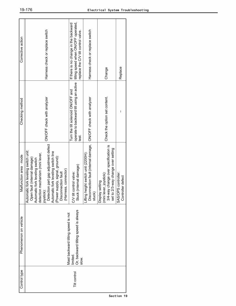
19-176
Tilt
cont
rol
Mas
t bac
kwar
d til
ting
spee
d is
not
lim
ited.
Or,
back
war
d til
ting
spee
d is
alw
ays
slow
.
Aut
omat
ic fo
rk le
velin
g sw
itch
unit:
Ope
n fa
ult (
inte
rnal
dam
age)
Aut
omat
ic fo
rk le
velin
g sw
itch
dete
ctio
n m
echa
nism
(min
i lev
er,
joys
tick)
:D
etec
tion
part
gap
adju
stm
ent d
efec
tA
utom
atic
fork
leve
ling
switc
h lin
e(P
ower
sup
ply,
sig
nal,
grou
nd):
Dis
conn
ectio
n fa
ult
(Har
ness
, con
nect
or)
ON
/OFF
che
ck w
ith a
naly
zer
Har
ness
che
ck o
r rep
lace
sw
itch
C/V
tilt
cont
rol v
alve
:St
uck
(inte
rnal
dam
age)
Turn
the
tilt s
olen
oid
ON
/OFF
and
op
erat
e to
bac
kwar
d til
t usi
ng a
n ac
tive
test
.
If th
ere
is n
o ch
ange
in th
e ba
ckw
ard
tiltin
g sp
eed
whe
n O
N/O
FF o
pera
ted,
re
plac
e th
e C
/V ti
lt co
ntro
l val
ve.
Lifti
ng h
eigh
t sw
itch
unit
(220
0H):
Dis
conn
ectio
n fa
ult (
inte
rnal
dam
age,
st
uck)
ON
/OFF
che
ck w
ith a
naly
zer
Har
ness
che
ck o
r rep
lace
sw
itch
Dis
play
set
ting
(min
i lev
er, j
oyst
ick)
: 3/
4-w
ay c
hang
e ov
er s
peci
ficat
ion
is
set t
o 2/
3-w
ay c
hang
e ov
er s
ettin
g
Che
ck th
e op
tion
set c
onte
nt.
Cha
nge
SAS
/OP
S co
ntro
ller:
Con
trolle
r def
ect
–R
epla
ce
Con
trol t
ype
Phen
omen
on o
n ve
hicl
eM
alfu
nctio
n ar
ea ·
mod
eC
heck
ing
met
hod
Cor
rect
ive
actio
n
Electrical System Troubleshooting
Section 19
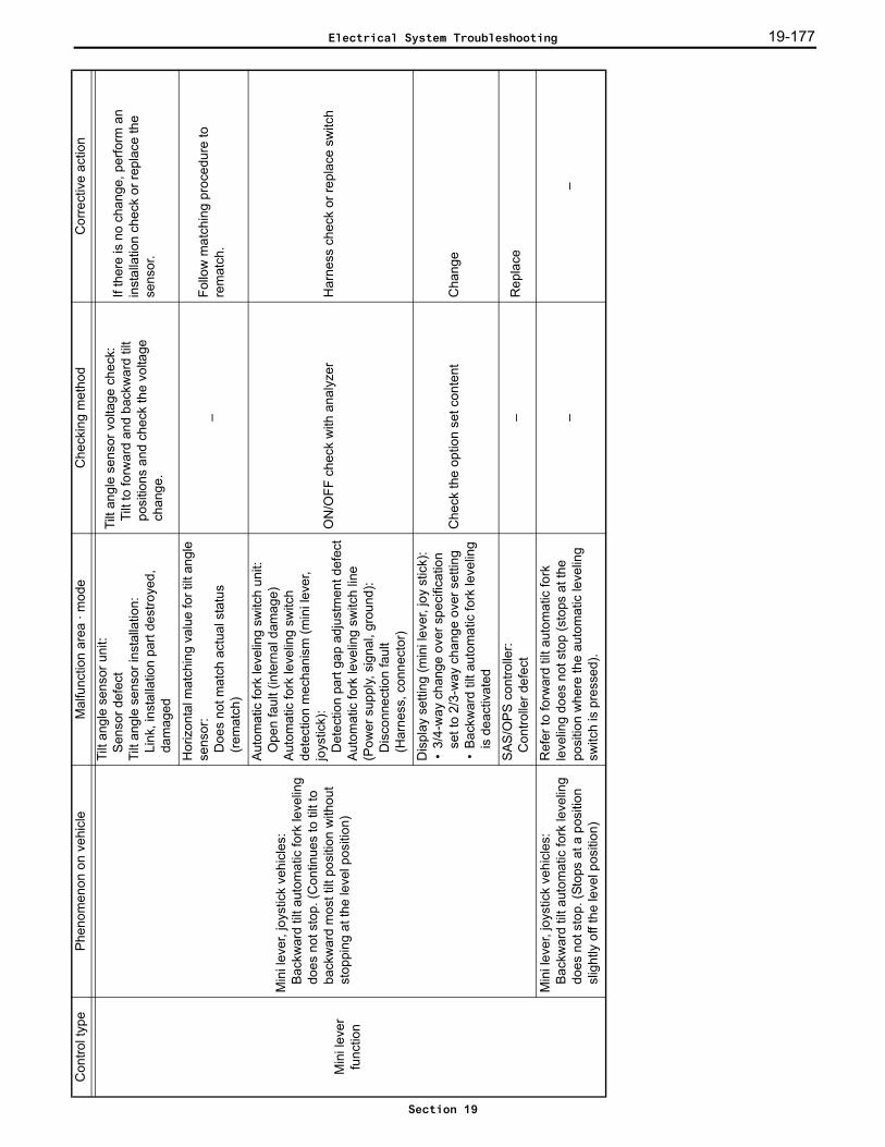
19-177
Min
i lev
er
func
tion
Min
i lev
er, j
oyst
ick
vehi
cles
:B
ackw
ard
tilt a
utom
atic
fork
leve
ling
does
not
sto
p. (C
ontin
ues
to ti
lt to
ba
ckw
ard
mos
t tilt
pos
ition
with
out
stop
ping
at t
he le
vel p
ositi
on)
Tilt
angl
e se
nsor
uni
t:S
enso
r def
ect
Tilt
angl
e se
nsor
inst
alla
tion:
Link
, ins
talla
tion
part
dest
roye
d,
dam
aged
Tilt
angl
e se
nsor
vol
tage
che
ck:
Tilt
to fo
rwar
d an
d ba
ckw
ard
tilt
posi
tions
and
che
ck th
e vo
ltage
ch
ange
.
If th
ere
is n
o ch
ange
, per
form
an
inst
alla
tion
chec
k or
repl
ace
the
sens
or.
Hor
izon
tal m
atch
ing
valu
e fo
r tilt
ang
le
sens
or:
Doe
s no
t mat
ch a
ctua
l sta
tus
(rem
atch
)
–Fo
llow
mat
chin
g pr
oced
ure
to
rem
atch
.
Aut
omat
ic fo
rk le
velin
g sw
itch
unit:
Ope
n fa
ult (
inte
rnal
dam
age)
Aut
omat
ic fo
rk le
velin
g sw
itch
dete
ctio
n m
echa
nism
(min
i lev
er,
joys
tick)
:D
etec
tion
part
gap
adju
stm
ent d
efec
tA
utom
atic
fork
leve
ling
switc
h lin
e(P
ower
sup
ply,
sig
nal,
grou
nd):
Dis
conn
ectio
n fa
ult
(Har
ness
, con
nect
or)
ON
/OFF
che
ck w
ith a
naly
zer
Har
ness
che
ck o
r rep
lace
sw
itch
Dis
play
set
ting
(min
i lev
er, j
oy s
tick)
:•
3/4-
way
cha
nge
over
spe
cific
atio
n se
t to
2/3-
way
cha
nge
over
set
ting
•B
ackw
ard
tilt a
utom
atic
fork
leve
ling
is d
eact
ivat
ed
Che
ck th
e op
tion
set c
onte
ntC
hang
e
SAS
/OP
S co
ntro
ller:
Con
trolle
r def
ect
–R
epla
ce
Min
i lev
er, j
oyst
ick
vehi
cles
:B
ackw
ard
tilt a
utom
atic
fork
leve
ling
does
not
sto
p. (S
tops
at a
pos
ition
sl
ight
ly o
ff th
e le
vel p
ositi
on)
Ref
er to
forw
ard
tilt a
utom
atic
fork
le
velin
g do
es n
ot s
top
(sto
ps a
t the
po
sitio
n w
here
the
auto
mat
ic le
velin
g sw
itch
is p
ress
ed).
––
Con
trol t
ype
Phen
omen
on o
n ve
hicl
eM
alfu
nctio
n ar
ea ·
mod
eC
heck
ing
met
hod
Cor
rect
ive
actio
n
Electrical System Troubleshooting
Section 19
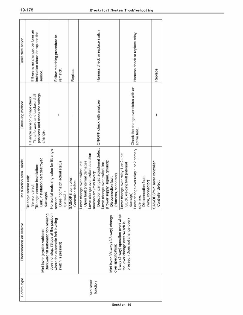
19-178
Min
i lev
er
func
tion
Min
i lev
er, j
oyst
ick
vehi
cles
:B
ackw
ard
tilt a
utom
atic
fork
leve
ling
does
not
sto
p. (S
tops
at t
he p
ositi
on
whe
re th
e au
tom
atic
fork
leve
ling
switc
h is
pre
ssed
)
Tilt
angl
e se
nsor
uni
t:S
enso
r def
ect
Tilt
angl
e se
nsor
inst
alla
tion:
Link
, ins
talla
tion
part
dest
roye
d,
dam
aged
Tilt
angl
e se
nsor
vol
tage
che
ck:
Tilt
to fo
rwar
d an
d ba
ckw
ard
tilt
posi
tions
and
che
ck th
e vo
ltage
ch
ange
.
If th
ere
is n
o ch
ange
, per
form
an
inst
alla
tion
chec
k or
repl
ace
the
sens
or.
Hor
izon
tal m
atch
ing
valu
e fo
r tilt
ang
le
sens
or:
Doe
s no
t mat
ch a
ctua
l sta
tus
(rem
atch
)
–Fo
llow
mat
chin
g pr
oced
ure
to
rem
atch
.
SAS
/OP
S co
ntro
ller:
Con
trolle
r def
ect
–R
epla
ce
Min
i lev
er 3
/4-w
ay (2
/3-w
ay) c
hang
e ov
er s
peci
ficat
ion:
3-
way
(2-w
ay) o
pera
tion
even
whe
n th
e le
ver c
hang
e ov
er s
witc
h is
pr
esse
d. (D
oes
not c
hang
e ov
er)
Leve
r cha
nge
over
sw
itch
unit:
Ope
n fa
ult (
inte
rnal
dam
age)
Leve
r cha
nge
over
sw
itch
dete
ctio
n m
echa
nism
(min
i lev
er):
Det
ectio
n pa
rt ga
p ad
just
men
t def
ect
Leve
r cha
nge
over
sw
itch
line
(Pow
er s
uppl
y, s
igna
l, gr
ound
):D
isco
nnec
tion
faul
t(H
arne
ss, c
onne
ctor
)
ON
/OFF
che
ck w
ith a
naly
zer
Har
ness
che
ck o
r rep
lace
sw
itch
Leve
r cha
nge
over
rela
y 1
or 2
uni
t: St
uck,
wel
ding
faul
t (in
tern
al
dam
age)
Leve
r cha
nge
over
rela
y 1
or 2
prim
ary
side
line
:D
isco
nnec
tion
faul
t(w
ire, c
onne
ctor
)
Che
ck th
e ch
ange
over
sta
tus
with
an
activ
e te
st.
Har
ness
che
ck o
r rep
lace
rela
y
SAS
/OP
S/m
ini l
ever
con
trolle
r:C
ontro
ller d
efec
t–
Rep
lace
Con
trol t
ype
Phen
omen
on o
n ve
hicl
eM
alfu
nctio
n ar
ea ·
mod
eC
heck
ing
met
hod
Cor
rect
ive
actio
n
Electrical System Troubleshooting
Section 19

19-179
Min
i lev
er
func
tion
Min
i lev
er 3
/4-w
ay (2
/3-w
ay) c
hang
e ov
er s
peci
ficat
ion:
4-w
ay (3
-way
) con
tinue
s to
ope
rate
ev
en th
ough
the
leve
r cha
nge
over
sw
itch
has
been
ope
rate
d. (S
tays
ch
ange
d ov
er)
Leve
r cha
nge
over
sw
itch
unit:
Gro
und
shor
t fau
lt (In
tern
al d
amag
e)Le
ver c
hang
e ov
er s
witc
h de
tect
ion
mec
hani
sm (m
ini l
ever
):D
etec
tion
part
gap
adju
stm
ent d
efec
tLe
ver c
hang
e ov
er s
witc
h lin
e(s
igna
l):G
roun
d sh
ort f
ault
(Har
ness
, con
nect
or)
ON
/OFF
che
ck w
ith a
naly
zer
Har
ness
che
ck o
r rep
lace
sw
itch
Leve
r cha
nge
over
rela
y 1
or 2
uni
t:St
uck,
wel
ding
faul
t (in
tern
al
dam
age)
Leve
r cha
nge
over
rela
y 1
or 2
prim
ary
side
low
er li
ne:
Gro
und
shor
t fau
lt(w
ire, c
onne
ctor
)
Che
ck th
e ch
ange
over
sta
tus
with
an
activ
e te
st.
Har
ness
che
ck o
r rep
lace
rela
y
Dis
play
set
ting:
Num
ber o
f atta
chm
ent l
ever
s is
not
se
t to
5 w
ayC
heck
the
optio
n se
t con
tent
.C
hang
e
SAS
/OP
S co
ntro
ller:
Con
trolle
r def
ect
–R
epla
ce
Min
i lev
er 2
/3-w
ay c
hang
e ov
er
spec
ifica
tion:
Dur
ing
ATT1
ope
ratio
n an
d hi
gh
liftin
g he
ight
, and
whe
n lo
aded
, ATT
1 st
ops
and
pull-
side
ope
ratio
n is
slo
w.
Dis
play
set
ting:
Num
ber o
f atta
chm
ent l
ever
s is
not
se
t to
2/3-
way
Che
ck th
e op
tion
set c
onte
nt.
Cha
nge
3-w
ay (4
-way
) spe
cifc
atio
n:Al
thou
gh A
TT1
(ATT
2) is
ope
rate
d, it
do
es n
ot w
ork.
Dis
play
set
ting:
Num
ber o
f atta
chm
ent l
ever
s is
not
se
t to
3-w
ay (4
-way
)C
heck
the
optio
n se
t con
tent
.C
hang
e
Con
trol t
ype
Phen
omen
on o
n ve
hicl
eM
alfu
nctio
n ar
ea ·
mod
eC
heck
ing
met
hod
Cor
rect
ive
actio
n
Electrical System Troubleshooting
Section 19

19-180
Knob
co
mpe
nsai
ton
cont
rol
Knob
mov
es o
ut o
f alig
nmen
t int
o a
certa
in p
ositi
on.
(Mor
e th
an 1
0° o
ff th
e st
raig
ht a
head
po
sitio
n)
Tire
ang
le s
enso
r uni
t:S
enso
r def
ect
Tire
ang
le s
enso
r ins
talla
tion:
Loos
enes
s of
the
atta
chm
ent p
art,
dam
age,
bea
ring
hous
ing
dam
age
Tire
ang
le s
enso
r vol
tage
che
ck:
Ope
rate
the
stee
ring
and
chec
k th
e ch
ange
in v
olta
ge.
If th
ere
is n
o ch
ange
, per
form
an
inst
alla
tion
chec
k or
repl
ace
the
sens
or.
Tire
ang
le s
enso
r mat
chin
g va
lue:
Doe
s no
t mat
ch a
ctua
l sta
tus
(rem
atch
)–
Follo
w m
atch
ing
proc
edur
e to
re
mat
ch.
Stee
ring
angl
e se
nsor
uni
t:S
enso
r def
ect
Stee
ring
angl
e se
nsor
inst
alla
tion:
Cam
or s
teer
ing
whe
el d
efec
t
ON
/OFF
che
ck w
ith a
naly
zer
Har
ness
che
ck o
r rep
lace
sen
sor
Kno
b co
mpe
nsat
ion
valv
e un
it:
Leak
, stu
ck, (
inte
rnal
dam
age)
Usi
ng a
n ac
tive
test
, tur
n th
e kn
ob
com
pens
atio
n SO
L O
N a
nd O
FF a
nd
oper
ate
the
stee
ring
at th
e tir
e en
d.SO
L O
N: c
heck
that
the
stee
ring
whe
el c
an b
e tu
rned
free
ly.S
OL
OFF
: Che
ck th
at th
e st
eerin
g w
heel
can
not b
e tu
rned
free
ly
(ste
erin
g is
hea
vy).
Rep
lace
SAS
/OP
S co
ntro
ller:
Con
trolle
r def
ect
–R
epla
ce
Con
trol t
ype
Phen
omen
on o
n ve
hicl
eM
alfu
nctio
n ar
ea ·
mod
eC
heck
ing
met
hod
Cor
rect
ive
actio
n
Electrical System Troubleshooting
Section 19

19-181
Knob
co
mpe
nsat
ion
cont
rol
Knob
pos
ition
is o
ut o
f alig
nmen
t.(K
nob
posi
tion
is n
ot c
onst
ant w
hen
trave
ling
stra
ight
ahe
ad)
Tire
ang
le s
enso
r uni
t:S
enso
r def
ect
Tire
ang
le s
enso
r ins
talla
tion:
Loos
enes
s of
the
atta
chm
ent p
art,
dam
age,
bea
ring
hous
ing
dam
age
Tire
ang
le s
enso
r vol
tage
che
ck:
Ope
rate
the
stee
ring
and
chec
k th
e ch
ange
in v
olta
ge.
If th
ere
is n
o ch
ange
, per
form
an
inst
alla
tion
chec
k or
repl
ace
the
sens
or.
Tire
ang
le s
enso
r mat
chin
g va
lue:
Doe
s no
t mat
ch a
ctua
l sta
tus
(rem
atch
)–
Follo
w m
atch
ing
proc
edur
e to
re
mat
ch.
Stee
ring
angl
e se
nsor
uni
t:S
enso
r def
ect
Stee
ring
angl
e se
nsor
inst
alla
tion:
Cam
or s
teer
ing
whe
el d
efec
t
Che
ck s
enso
r vol
tage
with
the
anal
yzer
.H
arne
ss c
heck
or r
epla
ce s
enso
r
Knob
com
pens
atio
n va
lve
unit:
Leak
, stu
ck, (
inte
rnal
dam
age)
Usi
ng a
n ac
tive
test
, tur
n th
e kn
ob
com
pens
atio
n SO
L O
N a
nd O
FF a
nd
oper
ate
the
stee
ring
at th
e tir
e en
d.SO
L O
N: C
heck
that
the
stee
ring
whe
el c
an b
e tu
rned
free
ly.S
OL
OFF
: Che
ck th
at th
e st
eerin
g w
heel
can
not b
e tu
rned
free
ly
(ste
erin
g is
hea
vy).
Rep
lace
PS
cylin
der s
yste
m li
nk d
efec
t:Ec
cent
ric p
in, k
ingp
in d
efec
t–
Rep
lace
Vehi
cle
spee
d se
nsor
uni
t:C
anno
t det
ect l
ow s
peed
(int
erna
l da
mag
e)Ve
hicl
e sp
eed
sens
or in
stal
latio
n:H
igh
spee
d no
t det
ecte
d co
rrect
ly(s
enso
r tip
has
met
allic
par
ticle
ad
here
d)Ve
hicl
e sp
eed
sens
or li
ne(S
PD
+ si
de, S
PD- s
ide)
:Le
ak fa
ult
(Har
ness
, con
nect
or)
Che
ck s
enso
r vol
tage
and
veh
icle
sp
eed
with
the
anal
yzer
.
If th
ere
is n
o ch
ange
, per
form
an
inst
alla
tion
chec
k or
repl
ace
the
sens
or.
SAS
/OP
S co
ntro
ller:
Con
trolle
r def
ect
–R
epla
ce
Con
trol t
ype
Phen
omen
on o
n ve
hicl
eM
alfu
nctio
n ar
ea ·
mod
eC
heck
ing
met
hod
Cor
rect
ive
actio
n
Electrical System Troubleshooting
Section 19
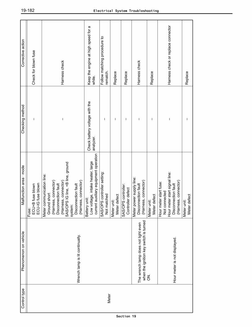
19-182
Met
er
Wre
nch
lam
p is
lit c
ontin
ually
.
Fuse
:EC
U+B
fuse
blo
wn
EC
U-IG
fuse
blo
wn
–C
heck
for b
low
n fu
se
Met
er c
omm
unic
atio
n lin
e:
Gro
und
shor
t(H
arne
ss, c
onne
ctor
)D
isco
nnec
tion
faul
t(H
arne
ss, c
onne
ctor
)SA
S/O
PS IG
line
, +B
line
, gro
und
syst
em:
Dis
conn
ectio
n fa
ult
(Har
ness
, con
nect
or)
–H
arne
ss c
heck
Bat
tery
uni
t: Lo
w v
olta
ge, i
ntak
e he
ater
, lar
ge
curre
nt a
uxili
ary
equi
pmen
t ope
ratio
n
Che
ck b
atte
ry v
olta
ge w
ith th
e an
alyz
er.
Keep
the
engi
ne a
t hig
h sp
eed
for a
w
hile
.
SAS
/OP
S co
ntro
ller s
ettin
g:N
ot m
atch
ed–
Follo
w m
atch
ing
proc
edur
e to
re
mat
ch.
Met
er u
nit:
Met
er d
efec
t–
Rep
lace
SAS
/OP
S co
ntro
ller:
Con
trolle
r def
ect
–R
epla
ce
The
wre
nch
lam
p do
es n
ot li
ght e
ven
whe
n th
e ig
nitio
n ke
y sw
itch
is tu
rned
O
N.
Met
er p
ower
sup
ply
line:
Dis
conn
ectio
n fa
ult
(Har
ness
, con
nect
or)
–H
arne
ss c
heck
Met
er u
nit:
Met
er d
efec
t–
Rep
lace
Hou
r met
er is
not
dis
play
ed.
Hou
r met
er s
tart
fuse
: N
ot c
onne
cted
Hou
r met
er s
tart
sign
al li
ne:
Dis
conn
ectio
n fa
ult
(Har
ness
, con
nect
or)
–H
arne
ss c
heck
or r
epla
ce c
onne
ctor
Met
er u
nit:
Met
er d
efec
t–
Rep
lace
Con
trol t
ype
Phen
omen
on o
n ve
hicl
eM
alfu
nctio
n ar
ea ·
mod
eC
heck
ing
met
hod
Cor
rect
ive
actio
n
Electrical System Troubleshooting
Section 19

19-183
OP
S
For c
owl l
ever
veh
icle
s:C
anno
t low
er th
e lif
t.
Lift
low
er s
witc
h un
it:O
pen
faul
t(S
witc
h m
ount
ed in
corre
ctly,
inte
rnal
dam
age,
stu
ck)
Lift
low
er s
witc
h lin
e:D
isco
nnec
tion
faul
t(H
arne
ss, c
onne
ctor
)Sw
itch
grou
nd li
ne:
Dis
conn
ectio
n fa
ult
(Har
ness
, con
nect
or)
ON
/OFF
che
ck w
ith a
naly
zer
Har
ness
che
ck o
r rep
lace
sw
itch
C/V
lift
low
er lo
ck v
alve
Stuc
k (in
tern
al d
amag
e)
Usi
ng a
n ac
tive
test
, tur
n th
e lif
t low
er
lock
sol
enoi
d O
N a
nd p
erfo
rm lo
wer
op
erat
ion.
If th
e lif
t can
not l
ower
by
low
er
oper
atio
n, re
plac
e th
e C
/V.
Seat
sw
itch
unit:
Ope
n fa
ult (
inte
rnal
dam
age)
Seat
sw
itch
line
(Sig
nal,
grou
nd):
Dis
conn
ectio
n fa
ult
(Har
ness
, con
nect
or)
ON
/OFF
che
ck w
ith a
naly
zer
Har
ness
che
ck o
r rep
lace
sw
itch
For c
owl l
ever
veh
icle
s:C
anno
t per
form
forw
ard
tilt.
Forw
ard
tilt s
witc
h un
it:O
pen
faul
t(S
witc
h m
ount
ed in
corre
ctly,
inte
rnal
dam
age,
stu
ck)
Forw
ard
tilt s
witc
h lin
e:D
isco
nnec
tion
faul
t(H
arne
ss, c
onne
ctor
)Sw
itch
grou
nd li
ne:
Dis
conn
ectio
n fa
ult
(Har
ness
, con
nect
or)
ON
/OFF
che
ck w
ith a
naly
zer
Har
ness
che
ck o
r rep
lace
sw
itch
C/V
tilt
cont
rol v
alve
Stuc
k (in
tern
al d
amag
e)Tu
rn th
e til
t sol
enoi
d O
N a
nd o
pera
te
to fo
rwar
d til
t usi
ng a
n ac
tive
test
.If
forw
ard
tilt c
anno
t be
perfo
rmed
, re
plac
e th
e C
/V ti
lt co
ntro
l val
ve.
Seat
sw
itch
unit:
Ope
n fa
ult (
inte
rnal
dam
age)
Seat
sw
itch
line
(Sig
nal,
grou
nd):
Dis
conn
ectio
n fa
ult
(Har
ness
, con
nect
or)
ON
/OFF
che
ck w
ith a
naly
zer
Har
ness
che
ck o
r rep
lace
sw
itch
Con
trol t
ype
Phen
omen
on o
n ve
hicl
eM
alfu
nctio
n ar
ea ·
mod
eC
heck
ing
met
hod
Cor
rect
ive
actio
n
Electrical System Troubleshooting
Section 19
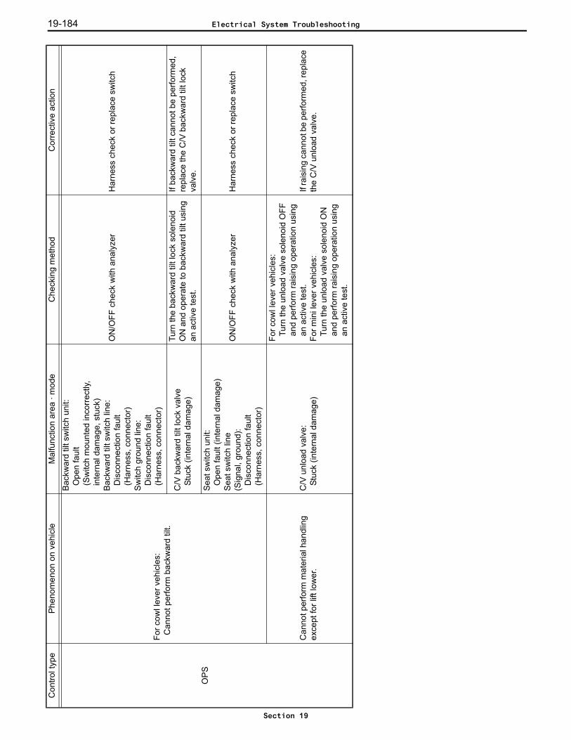
19-184
OP
S
For c
owl l
ever
veh
icle
s:C
anno
t per
form
bac
kwar
d til
t.
Bac
kwar
d til
t sw
itch
unit:
Ope
n fa
ult
(Sw
itch
mou
nted
inco
rrect
ly,in
tern
al d
amag
e, s
tuck
)B
ackw
ard
tilt s
witc
h lin
e:D
isco
nnec
tion
faul
t(H
arne
ss, c
onne
ctor
)Sw
itch
grou
nd li
ne:
Dis
conn
ectio
n fa
ult
(Har
ness
, con
nect
or)
ON
/OFF
che
ck w
ith a
naly
zer
Har
ness
che
ck o
r rep
lace
sw
itch
C/V
bac
kwar
d til
t loc
k va
lve
Stuc
k (in
tern
al d
amag
e)
Turn
the
back
war
d til
t loc
k so
leno
id
ON
and
ope
rate
to b
ackw
ard
tilt u
sing
an
act
ive
test
.
If ba
ckw
ard
tilt c
anno
t be
perfo
rmed
, re
plac
e th
e C
/V b
ackw
ard
tilt l
ock
valv
e.
Seat
sw
itch
unit:
Ope
n fa
ult (
inte
rnal
dam
age)
Seat
sw
itch
line
(Sig
nal,
grou
nd):
Dis
conn
ectio
n fa
ult
(Har
ness
, con
nect
or)
ON
/OFF
che
ck w
ith a
naly
zer
Har
ness
che
ck o
r rep
lace
sw
itch
Can
not p
erfo
rm m
ater
ial h
andl
ing
exce
pt fo
r lift
low
er.
C/V
unl
oad
valv
e:St
uck
(inte
rnal
dam
age)
For c
owl l
ever
veh
icle
s:Tu
rn th
e un
load
val
ve s
olen
oid
OFF
an
d pe
rform
rais
ing
oper
atio
n us
ing
an a
ctiv
e te
st.
For m
ini l
ever
veh
icle
s:Tu
rn th
e un
load
val
ve s
olen
oid
ON
an
d pe
rform
rais
ing
oper
atio
n us
ing
an a
ctiv
e te
st.
If ra
isin
g ca
nnot
be
perfo
rmed
, rep
lace
th
e C
/V u
nloa
d va
lve.
Con
trol t
ype
Phen
omen
on o
n ve
hicl
eM
alfu
nctio
n ar
ea ·
mod
eC
heck
ing
met
hod
Cor
rect
ive
actio
n
Electrical System Troubleshooting
Section 19
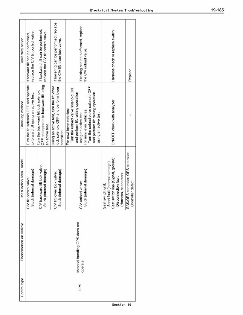
19-185
OP
SM
ater
ial h
andl
ing
OPS
doe
s no
t op
erat
e.
C/V
tilt
cont
rol v
alve
:St
uck
(inte
rnal
dam
age)
Turn
the
tilt s
olen
oid
OFF
and
ope
rate
to
forw
ard
tilt u
sing
an
activ
e te
st.
If fo
rwar
d til
t can
be
perfo
rmed
, re
plac
e th
e C
/V ti
lt co
ntro
l val
ve.
C/V
bac
kwar
d til
t loc
k va
lve:
Stuc
k (in
tern
al d
amag
e)
Turn
the
back
war
d til
t loc
k so
leno
id
OFF
and
ope
rate
to b
ackw
ard
tilt u
sing
an
act
ive
test
.
If ba
ckw
ard
tilt c
an b
e pe
rform
ed,
repl
ace
the
C/V
tilt
cont
rol v
alve
.
C/V
lift
low
er lo
ck v
alve
: St
uck
(inte
rnal
dam
age)
Usi
ng a
n ac
tive
test
, tur
n th
e lif
t low
er
lock
sol
enoi
d O
FF a
nd p
erfo
rm lo
wer
op
erat
ion.
If lo
wer
ing
can
be p
erfo
rmed
, rep
lace
th
e C
/V li
ft lo
wer
lock
val
ve.
C/V
unl
oad
valv
e:St
uck
(inte
rnal
dam
age)
For c
owl l
ever
veh
icle
s:Tu
rn th
e un
load
val
ve s
olen
oid
ON
an
d pe
rform
lift
rais
ing
oper
atio
n us
ing
an a
ctiv
e te
st.
For m
ini l
ever
veh
icle
s:Tu
rn th
e un
load
val
ve s
olen
oid
OFF
an
d pe
rform
lift
rais
ing
oper
atio
n us
ing
an a
ctiv
e te
st.
If ra
isin
g ca
n be
per
form
ed, r
epla
ce
the
C/V
unl
oad
valv
e.
Seat
sw
itch
unit:
Shor
t fau
lt (in
tern
al d
amag
e)Se
at s
witc
h lin
e (S
igna
l, gr
ound
):D
isco
nnec
tion
faul
t (H
arne
ss, c
onne
ctor
)
ON
/OFF
che
ck w
ith a
naly
zer
Har
ness
che
ck o
r rep
lace
sw
itch
SAS
/OP
S co
ntro
ller,
OP
S co
ntro
ller:
Con
trolle
r def
ect
–R
epla
ce
Con
trol t
ype
Phen
omen
on o
n ve
hicl
eM
alfu
nctio
n ar
ea ·
mod
eC
heck
ing
met
hod
Cor
rect
ive
actio
n
Electrical System Troubleshooting
Section 19
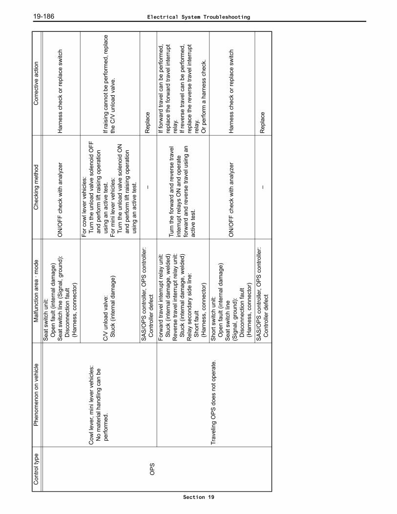
19-186
OP
S
Cow
l lev
er, m
ini l
ever
veh
icle
s:N
o m
ater
ial h
andl
ing
can
be
perfo
rmed
.
Seat
sw
itch
unit:
Ope
n fa
ult (
inte
rnal
dam
age)
Seat
sw
itch
line
(Sig
nal,
grou
nd):
Dis
conn
ectio
n fa
ult
(Har
ness
, con
nect
or)
ON
/OFF
che
ck w
ith a
naly
zer
Har
ness
che
ck o
r rep
lace
sw
itch
C/V
unl
oad
valv
e:St
uck
(inte
rnal
dam
age)
For c
owl l
ever
veh
icle
s:Tu
rn th
e un
load
val
ve s
olen
oid
OFF
an
d pe
rform
lift
rais
ing
oper
atio
n us
ing
an a
ctiv
e te
st.
For m
ini l
ever
veh
icle
s:Tu
rn th
e un
load
val
ve s
olen
oid
ON
an
d pe
rform
lift
rais
ing
oper
atio
n us
ing
an a
ctiv
e te
st.
If ra
isin
g ca
nnot
be
perfo
rmed
, rep
lace
th
e C
/V u
nloa
d va
lve.
SAS
/OP
S co
ntro
ller,
OP
S co
ntro
ller:
Con
trolle
r def
ect
–R
epla
ce
Trav
elin
g O
PS d
oes
not o
pera
te.
Forw
ard
trave
l int
erru
pt re
lay
unit:
St
uck
(inte
rnal
dam
age,
wel
ded)
Rev
erse
trav
el in
terru
pt re
lay
unit:
Stuc
k (in
tern
al d
amag
e, w
elde
d)R
elay
sec
onda
ry s
ide
line:
Sh
ort f
ault
(Har
ness
, con
nect
or)
Turn
the
forw
ard
and
reve
rse
trave
l in
terru
pt re
lays
ON
and
ope
rate
fo
rwar
d an
d re
vers
e tra
vel u
sing
an
activ
e te
st.
If fo
rwar
d tra
vel c
an b
e pe
rform
ed,
repl
ace
the
forw
ard
trave
l int
erru
pt
rela
y.If
reve
rse
trave
l can
be
perfo
rmed
, re
plac
e th
e re
vers
e tra
vel i
nter
rupt
re
lay.
Or p
erfo
rm a
har
ness
che
ck.
Sho
rt sw
itch
unit:
Ope
n fa
ult (
inte
rnal
dam
age)
Seat
sw
itch
line
(Sig
nal,
grou
nd):
Dis
conn
ectio
n fa
ult
(Har
ness
, con
nect
or)
ON
/OFF
che
ck w
ith a
naly
zer
Har
ness
che
ck o
r rep
lace
sw
itch
SAS
/OP
S co
ntro
ller,
OP
S co
ntro
ller:
Con
trolle
r def
ect
–R
epla
ce
Con
trol t
ype
Phen
omen
on o
n ve
hicl
eM
alfu
nctio
n ar
ea ·
mod
eC
heck
ing
met
hod
Cor
rect
ive
actio
n
Electrical System Troubleshooting
Section 19
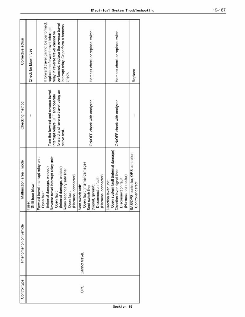
19-187
OPS
Can
not t
rave
l.
Fuse
:S
hift
fuse
blo
wn
–C
heck
for b
low
n fu
se
Forw
ard
trave
l int
erru
pt re
lay
unit:
Ope
n fa
ult
(inte
rnal
dam
age,
wel
ded)
Rev
erse
trav
el in
terru
pt re
lay
unit:
Ope
n fa
ult
(inte
rnal
dam
age,
wel
ded)
Rel
ay s
econ
dary
sid
e lin
e:O
pen
faul
t(H
arne
ss, c
onne
ctor
)
Turn
the
forw
ard
and
reve
rse
trave
l in
terru
pt re
lays
OFF
and
ope
rate
fo
rwar
d an
d re
vers
e tra
vel u
sing
an
activ
e te
st.
If fo
rwar
d tra
vel c
anno
t be
perfo
rmed
, re
plac
e th
e fo
rwar
d tra
vel i
nter
rupt
re
lay.
If re
vers
e tra
vel c
anno
t be
perfo
rmed
, rep
lace
the
reve
rse
trave
l in
terru
pt re
lay.
Or p
erfo
rm a
har
ness
ch
eck.
Seat
sw
itch
unit:
Ope
n fa
ult (
inte
rnal
dam
age)
Seat
sw
itch
line
(Sig
nal,
grou
nd):
Dis
conn
ectio
n fa
ult
(Har
ness
, con
nect
or)
ON
/OFF
che
ck w
ith a
naly
zer
Har
ness
che
ck o
r rep
lace
sw
itch
Dire
ctio
n le
ver u
nit:
Ope
n sy
stem
faul
t (in
tern
al d
amag
e)D
irect
ion
leve
r sig
nal l
ine:
Dis
conn
ectio
n fa
ult
(Har
ness
, con
nect
or)
ON
/OFF
che
ck w
ith a
naly
zer
Har
ness
che
ck o
r rep
lace
sw
itch
SAS
/OP
S co
ntro
ller,
OP
S co
ntro
ller:
Con
trolle
r def
ect
–R
epla
ce
Con
trol t
ype
Phen
omen
on o
n ve
hicl
eM
alfu
nctio
n ar
ea ·
mod
eC
heck
ing
met
hod
Cor
rect
ive
actio
n
Electrical System Troubleshooting
Section 19

19-188
Torq
ue
conv
erte
r in
terlo
ck
The
vehi
cle
cann
ot tr
avel
.
Torq
ue c
onve
rter i
nter
lock
rela
y m
ain
unit
for f
orw
ard
mov
emen
t:An
ope
n ci
rcui
t (in
tern
al d
amag
e)To
rque
con
verte
r int
erlo
ck re
lay
mai
n un
it fo
r bac
kwar
d m
ovem
ent:
An o
pen
circ
uit (
inte
rnal
dam
age)
Rel
ay s
econ
dary
line
:A
n op
en c
ircui
t (h
arne
sses
, con
nect
ors)
–
Che
ck th
e ha
rnes
ses.
If
the
vehi
cle
cann
ot tr
avel
forw
ard,
re
plac
e th
e to
rque
con
verte
r int
erlo
ck
rela
y fo
r for
war
d m
ovem
ent.
If th
e ve
hicl
e ca
nnot
trav
el b
ackw
ard,
re
plac
e th
e to
rque
con
verte
r int
erlo
ck
rela
y fo
r bac
kwar
d m
ovem
ent.
SAS
/OP
S co
ntro
ller:
Inte
rnal
dam
age
–R
epla
ce th
e co
ntro
ller.
The
torq
ue c
onve
rter i
nter
lock
doe
s no
t ope
rate
.
SAS
/OP
S co
ntro
ller i
s se
t:O
ptio
n se
t is
not s
et–
Set t
he c
ontro
ller a
gain
acc
ordi
ng to
th
e op
tion
set p
roce
dure
.
Torq
ue c
onve
rter i
nter
lock
rela
y m
ain
unit
for f
orw
ard
mov
emen
t:An
ope
n ci
rcui
t (in
tern
al d
amag
e)To
rque
con
verte
r int
erlo
ck re
lay
mai
n un
it fo
r bac
kwar
d m
ovem
ent:
An o
pen
circ
uit (
inte
rnal
dam
age)
Rel
ay s
econ
dary
line
:Fr
ame
shor
t (ha
rnes
ses)
–
Che
ck th
e ha
rnes
ses.
If th
e ve
hicl
e ca
nnot
trav
el fo
rwar
d,
repl
ace
the
torq
ue c
onve
rter i
nter
lock
re
lay
for f
orw
ard
mov
emen
t.If
the
vehi
cle
cann
ot tr
avel
bac
kwar
d,
repl
ace
the
torq
ue c
onve
rter i
nter
lock
re
lay
for b
ackw
ard
mov
emen
t.
SAS
/OP
S co
ntro
ller:
Inte
rnal
dam
age
–R
epla
ce th
e co
ntro
ller.
Con
trol t
ype
Phen
omen
on o
n ve
hicl
eM
alfu
nctio
n ar
ea ·
mod
eC
heck
ing
met
hod
Cor
rect
ive
actio
n
Electrical System Troubleshooting
Section 19

19-189
Def
ect C
ause
s W
hen
Ther
e is
No
ASC
Err
or D
ispl
ay
Not
e:If
an e
rror
cod
e or
wre
nch
lam
p is
flas
hing
, rep
air i
t firs
t.
Phen
omen
on o
n ve
hicl
eM
alfu
nctio
n ar
ea ·
mod
eC
heck
ing
met
hod
Cor
rect
ive
actio
n
Occ
aiso
nally
full
spee
d is
not
reac
hed
even
with
the
acce
lera
tor p
edal
fully
de
pres
sed.
(NM
R s
peed
not
ach
eive
d)
NM
R s
witc
h un
it:Sw
itch
defe
ctN
MR
sw
itch
line:
D
isco
nnec
tion
faul
t(H
arne
ss, c
onne
ctor
)N
MR
sw
itch
adju
stm
ent:
Adju
stm
ent d
efec
t, se
al b
olt p
ositi
on
defe
ct o
r som
e ot
her m
echa
nica
l def
ect
ON
/OFF
che
ck w
ith a
naly
zer
Har
ness
che
ck o
rre
plac
e sw
itch,
or a
djus
t sw
itch,
adj
ust a
nd
repa
ir m
echa
nica
l par
ts.
AS
C c
ontro
ller:
Con
trolle
r def
ect
–R
epla
ce
Idle
spe
ed is
hig
her t
han
spec
ified
spe
ed
even
whe
n th
e ac
cele
rato
r ped
al is
not
de
pres
sed.
Idle
sw
itch
adju
stm
ent:
Adju
stm
ent d
efec
t or m
echa
nica
l def
ect
–S
witc
h ad
just
men
t
Acc
eler
ator
sen
sor:
Sens
or c
atch
ing,
mis
take
in p
roce
dure
du
ring
sens
or re
plac
emen
t (w
hen
the
sens
or is
ben
g re
plac
ed, i
f a C
4 se
ries
erro
r is
not c
reat
ed b
y tu
rnin
g th
e ig
nitio
n ke
y O
N w
hile
the
sens
or c
onne
ctor
is
disc
onne
cted
, the
fully
clo
sed
posi
tion
lear
ning
val
ue is
not
rese
t)
Che
ck a
ccel
erat
or s
enso
r vol
tage
with
the
anal
yzer
.
Acce
lera
tor s
enso
r adj
ustm
ent,
or, i
f a fa
ult
occu
rs a
fter s
enso
r rep
lace
men
t, tu
rn th
e ig
nitio
n ke
y O
N w
ith th
e ac
cele
rato
r sen
sor
conn
ecto
rs re
mov
ed, i
n or
der t
o cr
eate
an
erro
r onc
e.Th
en tu
rn th
e ig
nitio
n ke
y O
FF, c
onne
ct
conn
ecto
rs a
nd tu
rn th
e ig
nitio
n ke
y O
N
AS
C c
ontro
ller:
Con
trolle
r def
ect
–R
epla
ce
Eng
ine
rev
up is
poo
r or s
low
.
Dro
p in
bat
tery
vol
tage
: B
atte
ry li
fe, i
ntak
e he
ater
, afte
rhea
tC
heck
bat
tery
vol
tage
with
the
anal
yzer
.Ba
ttery
repl
acem
ent
AS
C c
ontro
ller:
Con
trolle
r def
ect
–R
epla
ce
Doe
s no
t rev
up
from
idlin
g
IGN
, +B
line
: D
isco
nnec
tion
faul
t(H
arne
ss, c
onne
ctor
, fus
e)G
ND
line
com
plet
e lo
ss:
Dis
conn
ectio
n fa
ult
(Har
ness
, con
nect
or)
Che
ck b
atte
ry v
olta
ge w
ith th
e an
alyz
er.
Har
ness
che
ck o
r rep
lace
fuse
AS
C c
ontro
ller:
Con
trolle
r def
ect
–R
epla
ce
Electrical System Troubleshooting
Section 19

…..This Page Intentionally Left Blank…..
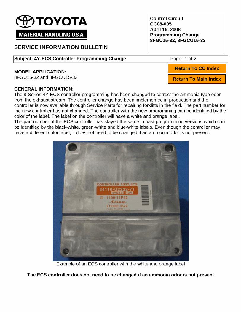
Control Circuit
CC08-005 April 15, 2008 Programming Change 8FGU15-32, 8FGCU15-32
SERVICE INFORMATION BULLETIN Subject: 4Y-ECS Controller Programming Change Page 1 of 2 Return To CC Index MODEL APPLICATION:
Return To Main Index 8FGU15-32 and 8FGCU15-32 GENERAL INFORMATION: The 8-Series 4Y-ECS controller programming has been changed to correct the ammonia type odor from the exhaust stream. The controller change has been implemented in production and the controller is now available through Service Parts for repairing forklifts in the field. The part number for the new controller has not changed. The controller with the new programming can be identified by the color of the label. The label on the controller will have a white and orange label. The part number of the ECS controller has stayed the same in past programming versions which can be identified by the black-white, green-white and blue-white labels. Even though the controller may have a different color label, it does not need to be changed if an ammonia odor is not present.
Example of an ECS controller with the white and orange label
The ECS controller does not need to be changed if an ammonia odor is not present.

SIB CC08-005 4Y-ECS Controller Programming Change Page 2 of 2
REPAIR INFORMATION: To change out the ECS controller:
1. Disconnect the battery. 2. Replace the ECS controller. 3. Reconnect the battery. 4. Once the controller is replaced. Verify that the ignition timing and fuel system are
adjusted correctly. Ignition Timing and Fuel System Adjustments: To check and adjust the ignition timing, reference page 2-18 of the 8-Series repair manual, 00700-X8880-71. TNB-2008-07 can be used as a reference and guide line for checking and making the adjustments to the fuel system. The idle mixture adjustment screw can be accessed by piercing the cap and prying it out of the sleeve.
Use a pick to pierce and pry out the cap for the idle
Mixture adjustment screw
Be sure the replace the tamper resistant cap, p/n 21673-13370-71, after making the any adjustments to the regulator. This is an EPA requirement. Frame Number Effective Range: 8FGU15-18 8FGU18-11533 and Higher 8FGU20-25 8FGU25-15748 and Higher 8FGU30-32 8FGU32-12676 and Higher 8FGCU15-S20 8FGCSU20-12589 and Higher 8FGCU20-25 8FGCU25-19092 and Higher 8FGCU30-32 8FGCU32-11833 and Higher
Chassis Electrical
CE07-008 November 30, 2007 Error Codes AD-1 and AD-7 8FG(C)U15-32
SERVICE INFORMATION BULLETIN Subject: Error Codes AD-1 and AD-7 Page 1 of 1 Return To CE Index MODEL APPLICATION:
Return To Main Index 8FGCU15-32 and 8FGU15-32 GENERAL INFORMATION: Error codes AD-1 and AD-7 are CAN Communication Abnormality error codes and can be set by installing a controller or optional display from one unit to another unit with different specifications, or when testing individual components and circuits. In either case, perform the “Engine and Display ECU information clear” procedure to clear the error codes. REPAIR INFORMATION: To perform the “Engine and Display ECU information clear” procedure, follow the instructions for SET 5 in the matching menu on page 16-29 of repair manual 00700-X8880-71.
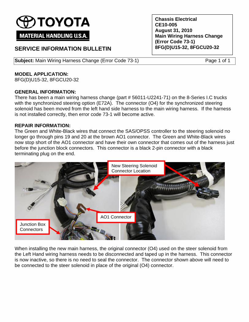
SERVICE INFORMATION BULLETIN Subject: Main Wiring Harness Change (Error Code 73-1) Page 1 of 1 MODEL APPLICATION: 8FG(D)U15-32, 8FGCU20-32 GENERAL INFORMATION: There has been a main wiring harness change (part # 56011-U2241-71) on the 8-Series I.C trucks with the synchronized steering option (E72A). The connector (O4) for the synchronized steering solenoid has been moved from the left hand side harness to the main wiring harness. If the harness is not installed correctly, then error code 73-1 will become active. REPAIR INFORMATION: The Green and White-Black wires that connect the SAS/OPSS controller to the steering solenoid no longer go through pins 19 and 20 at the brown AO1 connector. The Green and White-Black wires now stop short of the AO1 connector and have their own connector that comes out of the harness just before the junction block connectors. This connector is a black 2-pin connector with a black terminating plug on the end.
When installing the new main harness, the original connector (O4) used on the steer solenoid from the Left Hand wiring harness needs to be disconnected and taped up in the harness. This connector is now inactive, so there is no need to seal the connector. The connector shown above will need to be connected to the steer solenoid in place of the original (O4) connector.
Chassis Electrical CE10-005 August 31, 2010 Main Wiring Harness Change (Error Code 73-1) 8FG(D)U15-32, 8FGCU20-32
New Steering Solenoid Connector Location
AO1 Connector Junction Box Connectors
SERVICE INFORMATION BULLETIN Subject: A5, A5-1, or 1-1 Error Codes for OPSS Page 1 of 1 MODEL APPLICATION: 7FBCU15, 7FBCU18, 7FBCU20, 7FBCU25, 7FBCU30, 7FBCU32 7FBCU35, 7FBCU45, 7FBCU55, 7FBCHU18, 7FBCHU25 7FBEU15, 7FBEU18, 7FBEU20, 7FBEHU18, 7FGU15, 7FGU18 7FGU20, 7FGU25, 7FGU30, 7FGU32, 7FDU15, 7FDU18, 7FDU20 7FDU25, 7FDU30, 7FDU32, 8FGU15, 8FGU18, 8FGU20, 8FGU25 8FGU30, 8FGU32, 8FDU15, 8FDU18, 8FDU20, 8FDU25, 8FDU30 8FDU32, 7FGCU15, 7FGCU18, 7FGCU20, 7FGCSU20, 7FGCU25 7FGCU30, 7FGCU32, 8FGCU18, 8FGCU20, 8FGCSU20, 8FGCU25 8FGCU30, 8FGCU32, 7FGU35, 7FDU35, 7FGKU40, 7FDKU40 7FGU45, 7FDU45, 7FGAU50, 7FDAU50, 7FGU60, 7FDU60, 7FGU70 7FDU70, 7FGU80, 7FDU80, 7FGCU35, 7FGCU45, 7FGCU55 7FGCU60, 7FGCU70 GENERAL INFORMATION: All three error codes are for the same condition.
• A5 is for sit-down electric trucks (Class I) • A5-1 is for 8-Series internal combustion trucks (Class IV & V) • 1-1 is for 7-Series internal combustion trucks (Class IV & V) with OPSS (Operator Presence
Sensing System)
This system was implemented in 2005. The OPSS is required to check for a malfunctioning or bypassed seat switch circuit. To do this, the system stays active even when the key is off and monitors the seat switch. If the seat switch stays closed for more than 15 minutes with the key off, the system assumes that the switch has malfunctioned or been bypassed. The code will stay active until the system sees the seat switch circuit cycle open/closed, then will automatically clear. REPAIR INFORMATION: The most common cause for these seat switch codes is an operator staying in the seat. If an operator stays sitting in the seat with the truck turned off for 15 minutes, they will trip the seat code. Examples have been operators taking a break, lunch period, or filling out paperwork while sitting on the truck with the key off. The dealer has been called for a seat switch code and when the technician arrives, the code has cleared, but is stored in memory. This is because the operator left the truck while waiting for the technician; this cycled the seat switch and cleared the code. In many cases, the seat switch has been replaced unnecessarily due to this occurrence. Further information concerning these codes can be found in the following manuals: 7FBCU15-55 OPSS Manual CU335 page 3-9 7FBEU15-20 OPSS Manual CU341 page 1-10 7FGCU15, 18, S20 OPSS Manual CU042 page 1-19 7FGU15-32, 7FDU15-32, 7FGCU20-32 OPSS Manual CU040 page 1-18 7FGU35-80, 7FDU35-80, 7FGCU35-70 OPSS Manual CU041 page 1-17 8FGCU15, 18, S20 Service manual 00700-X8880-71 page 19.1-82 8FGU15-32, 8FDU15-32, 8FGCU20-32 Service manual 00700-X8880-71 page 19-111
Chassis Electrical CE09-004 October 30, 2009 A5, A5-1, or 1-1 Error Codes for OPSS